1
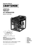
Owner's Manual
CRAFTSMAN+
120/240 Volt
Electric Start
10,000 Watt
AC GENERATOR
Model No 580.328300
CusGemn:/aHt°lpline_"
HOURS: Mon. - Fri. 8 a.m. to 5 p.m. (CT)
CAUTION:
Before using this product, read this
manual and follow all its Safety Rules
and Operating Instructions
Sears, Roebuck
and Co,
Hoffman
Estates,
Visit our Craftsman website: www.sears.com/craftsman
Part No. B4419
Draft 1 (6/14/2000)
Printed in the U.S.A.
IL 60179
•
•
•
•
•
•
Safety
Assembly
Operation
Maintenance
Parts
Espahol
Warranty ..................................
2
Safety Rules ...............................
Assembly ...............................
3
4-5
Operation ..............................
Maintenance ...........................
6-12
13-15
Product Specifications .......................
14
Storage ..................................
16
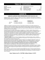
LIMITED WARRANTY
Troubleshooting ............................
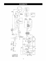
Schematic ................................
17
18
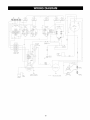
Wiring Diagram ............................
19
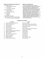
Replacement Parts ......................
20-37
Emissions Warranty ......................
Espa_ol ...............................
How to Order Parts ..................
38-39
40-59
Back Cover
FOR PORTABLE
GENERATORS
SEARS warrants to the original purchaser that the alternator and engine for its portable generator will be free
from defects in materials or workmanship for the items and period set forth below from the date of original
purchase. This warranty is not transferable.
CONSUMER*
COMMERCIAL*
Alternator
1 year labor, 2 years parts
1 year labor and parts
Engine
1 year labor, 2 years parts
1 year labor and parts
* NOTE: For the purpose of this warranty "Consumer Use" means personal residential household and
emergency use by original purchaser, not to be used as a primary source of power. "Commercial Use" means all
other uses, including rental, construction, commercial, and income producing purposes. Once a generator has
experienced commercial use, it shall thereafter be considered a commercial use generator for the purpose of
this warranty.
During said warranty period, SEARS will, at its option, repair or replace any part which, upon examination by
SEARS, is found to be defective under normal use and service**. Starting batteries are not warranted by
SEARS. All transportation costs under warranty, including return to the factory if necessary, are to be borne by
the purchaser and prepaid by him. This warranty does not cover normal maintenance and service and does not
apply to a generator set, alternator or engine, or parts which have been subjected to improper or unauthorized
installation or alteration, misuse, negligence, accident, overloading, overspeeding, improper maintenance, repair
or storage so as, in SEARS's judgment, to adversely affect its performance and reliability.
** NORMAL WEAR: As with all mechanical devices, engines need periodic parts service and replacement to
perform well. This warranty will not cover repair when normal use has exhausted the life of a part or engine.
THERE IS NO OTHER EXPRESS WARRANTY. SEARS HEREBY DISCLAIMS ANY AND ALL
IMPLIED WARRANTIES, INCLUDING BUT NOT LIMITED TO THOSE OF MERCHANTABILITY AND
FITNESS FOR A PARTICULAR PURPOSE TO THE EXTENT PERMITTED BY LAW. THE DURATION
OF ANY IMPLIED WARRANTIES WHICH CANNOT BE DISCLAIMED IS LIMITED TO THE TIME
PERIOD AS SPECIFIED IN THE EXPRESS WARRANTY. LIABILITY FOR CONSEQUENTIAL,
INCIDENTAL, OR SPECIAL DAMAGES UNDER ANY AND ALL WARRANTIES IS EXCLUDED.
Some states do not allow limitations on how long an implied warranty lasts, or the exclusion or limitation of
incidental or consequential damages, so the above limitations or exclusions may not apply to you. This warranty
gives you specific legal rights and you may also have other rights, which vary from state to state.
For service, see your nearest SEARS authorized warranty service facility. Warranty service can be performed
only by a SEARS authorized service facility. This warranty will not apply to service at any other facility. At the
time of requesting warranty service, evidence of original purchase date must be presented.
Sears, Roebuck
and Co., D/817WA,
Hoffman
Estates,
IL 60179
•
•
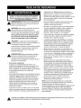
Never operate the generator:
in rain; in any enclosed compartment; when
connected electrical devices overheat; if electrical
output is lost; if engine or generator sparks; if flame
or smoke is observed while unit is running; if unit
vibrates excessively.
CAUTION! Before using this product, read this
manual and follow all Safety Rules and
Operating Instructions.
•
Never handle any kind of electrical cord or device
while standing in water, while barefoot or while
hands or feet are wet. Dangerous electrical shock
will result.
DANGER! You must isolate the generator from
the electric utility by opening the electrical
system's main circuit breaker or main switch if
this unit is used for backup power. Failure to
isolate the generator from the power utility may
result in injury or death to electric utility workers
and damage to the generator. When used as
backup power, the local power utility must be
notified.
•
Use a ground fault circuit interrupter in any damp
or highly conductive area (such as metal decking or
steel work).
•
Do Not use worn, bare, frayed or otherwise
damaged electrical cord sets with the generator.
Using any defective cord set may result in electrical
shock or damage to property.
•
Operate generator only on level surfaces and
where it will not be exposed to excessive moisture,
dirt, dust or corrosive vapors.
DANGER! Generator exhaust gases contain
DEADLY carbon monoxide gas. Carbon
monoxide, if breathed in sufficient
concentrations, will cause unconsciousness or
death. Operate this equipment outdoors where
adequate ventilation is available.
•
Gasoline is highly FLAMMABLE and its vapors are
EXPLOSIVE. Do Not permit smoking, open flames,
sparks or heat in the vicinity while handling
gasoline. Avoid spilling gasoline on a hot engine.
Comply with all laws regulating storage and
handling of gasoline.
•
CAUTION!
To prevent accidental starting when
setting up, transporting, adjusting or making
repairs to your generator, always disconnect
spark plug wire and place the wire where it
cannot contact the spark plug.
Never store generator with fuel in tank where
gasoline vapors might reach an open flame or
spark or pilot light (as on a furnace, water heater or
clothes dryer). FIRE or EXPLOSION may result.
•
•
The unit requires an adequate flow of cooling air
for its continued proper operation. Never operate
the unit inside any room or enclosure where the
free flow of cooling air into and out of the unit might
be obstructed. Allow at least 3 feet of clearance on
all sides of generator or you could damage the unit.
Never add fuel while unit is running.
Never start or stop the unit with electrical loads
connected to receptacles AND with connected
devices turned ON. Start the engine and let it
stabilize before connecting electrical loads.
Disconnect all electrical loads before shutting down
the generator.
•
Do Not insert any object through cooling slots of
the engine-generator.
•
The generator produces dangerously high voltage
that can cause extremely hazardous electrical
shock. Avoid contact with bare wires, terminals,
etc. Never permit any untrained person to operate
or service the generator.
•
Do Not overfill the fuel tank. Always allow room for
fuel expansion. If tank is overfilled, fuel can
overflow onto a hot engine and cause FIRE or an
EXPLOSION.
,_
NOTE: Your generator is equipped with a spark
arrester muffler The spark arrester must be maintained
in effective working order by the owner/operator.
In
the State of California, a spark arrester is required by
law (Section 4442 of the California Public Resources
Code). Other states may have similar laws. Federal
laws apply on federal lands.
THIS
IS THE INJURY
SAFETY HAZARDS.
ALERT SYMBOL.
IT ISSAFETY
USED TO
ALERT YOU
TO POTENTIAL
PERSONAL
OBEY ALL
MESSAGES
THAT
FOLLOW THIS
SYMBOL TO AVOID POSSIBLE INJURY OR DEATH.
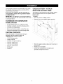
Your generator requires some assembly and is ready
for use after it has been properly serviced with the
recommended oil and fuel.
CHECK BATTERY / ATTACH
NEGATIVE BATTERY WIRE
If you have any problems with the assembly of
your generator, please call the generator helpline
at 1-800-222-3136.
The battery on the generator is fully charged, sealed
and pre-installed except for the negative (black)
battery cable.
To install:
IMPORTANT: Any attempt to run the engine before it
has been serviced with the recommended oil will result
in an engine failure.
•
Place key switch in "Stop" position.
•
Remove nut on the negative battery terminal.
•
Slide the negative battery cable over the screw on
the terminal.
•
Reattach nut and tighten.
•
Ensure the connections to the battery and
generator and tight and secure.
TO REMOVE THE GENERATOR
FROM CARTON
•
Set the palleted carton on a rigid flat surface.
•
Carefully cut bands around the shipping carton.
•
Lift carton off the generator.
•
Remove all packing material, carton fillers, etc.
•
Remove the generator from the shipping pallet.
CARTON
CONTENTS
Check all contents. If any parts are missing or
damaged, call the generator helpline at
1-800-222-3136. Contents Include:
•
•
10,000 Watt generator
Owner's manual
•
2 Bottles of engine oil (28 oz.)
•
125 Volt, 30 Amp plug
•
125 Volt, 20 Amp plug
•
240 Volt, 30 Amp plug
•
•
Oil fill spout
Wheel kit
4
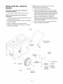
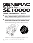
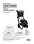
WHEEL
KIT INSTALLATION
NOTE: Be sure to install the wheel with the air
pressure valve outboard.
To install your wheel kit, you will need the following
tools:
•
5. Install other wheel in the same manner.
6. Secure the vibration mount on the support leg with
lock nut, washer, and 30mm long capscrew.
13mm metric box, open end or socket wrench
7. Fasten the support leg to the bottom of the
generator cradle using two 20 mm capscrews, two
lock washers and two flat washers. Remove
temporary blocks.
8. Position the handle below the muffler bracket on
the frame, as shown. Attach the handle with four
45mm long capscrews and four lock nuts.
Install Wheel Kit as follows:
1. Place the bottom of the generator cradle on a flat,
even surface. Place temporary blocks under the
cradle to ease assembly.
2. Slide axle through both axle mounting brackets on
cradle frame.
3. Slide spacer over each end of axle.
4. Install the wheel. Secure wheel on axle with
retaining pin and washer.
9. Recheck all nuts to make sure they are tight and
secure.
Handle
45mm
Capscrew
Locking
Nut
/
/
/
//
/
%
_
_
Locking
Nut
Support
Leg
J
J
\.
.J
__
/
Mount
Axle
_
M8 Flat
Spacer
Vibration
,/
Washer
/
Retaining
Pin
Flat Washer
/
_ Lock Washer
?_
Washer
30mm
Capscrew
g_
20mm
Capscrew
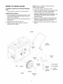
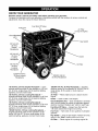
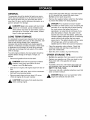
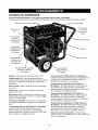
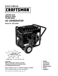
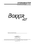
KNOW YOUR GENERATOR
Read the owner's manual and safety rules before operating your generator.
Compare the illustrations with your generator to familiarize yourself with the locations of various controls and
adjustments. Save this manual for future reference.
Fuel Shut Off Valve
FuelTank
Air Filter
(on top of engine)
Circuit Breakers
(AC)
Key Switch
120 Volt AC,
20 Amp
Duplex
Receptacle
120 Volt AC.
20 Amp
Locking
Receptacle
Choke
120 Volt AC,
30 Amp
Locking
Receptacle
120/240 Volt AC,
30 Amp Locking
Receptacle
120 Volt AC, 20 Amp Duplex Receptacle -- Each
supplies electrical power for the operation of 120 Volt
AC, 20 Amp, single phase, 60 Hz electrical lighting,
appliance, tool and motor loads.
120 Volt AC, 20 Amp Locking Receptacle -Supplies electrical power for the operation of 120 Volt
AC, 20 Amp, single phase, 60 Hz electrical lighting,
appliance, tool and motor loads.
120 Volt AC, 30 Amp Locking Receptacle -Supplies electrical power for the operation of 120 Volt
AC, 30 Amp, single phase, 60 Hz electrical lighting,
appliance, tool and motor loads.
120/240 Volt AC, 30 Amp Locking Receptacle -Supplies electrical power for the operation of 120
and/or 240 Volt AC, 30 Amp, single phase, 60 Hz
electrical lighting, appliance, tool and motor loads.
Oil Filter
120/240 Volt AC,
50 Amp Receptacle
120/240 Volt AC, 50 Amp Receptacle -- Supplies
electrical power for the operation of 120/240 Volt AC,
single phase, 60 Hz welder or motor loads at
50 Amps.
Air Filter -- Filters intake air as it is drawn into the
engine.
Choke -- Used to start a cold engine.
Circuit Breakers (AC) -- Each receptacle is provided
with a circuit breaker to protect the generator against
electrical overload. Breakers are "push to reset" type.
Fuel Shut-Off Valve -- Always have the fuel shut
-off valve closed when engine not running.
Fuel Tank -- Tank holds 10 U.S. gallons of unleaded
gasoline.
Key Switch -- Used to start engine. Always have key
switch in the "Stop" position when not in use.
Oil Filter-
Filters engine oil to prolong engine life.
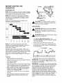
BEFORE STARTING
GENERATOR
Add Engine
THE
0,,Oau0e
Oil
NOTE: A 20 hour break-in period is required. Replace
engine oil and oil filter after the first 20 hours. Do Not
use synthetic oil during the break-in period.
Upper Level
NOTE: When adding oil to the engine crankcase in
the future, use only high quality detergent oil rated
with API service classification SF or higher. Use no
special additives.
Select the oil's viscosity grade according to your
expected operating temperature:
CAUTION! Your engine requires a break-in
period of 20 hours. Change oil and filter after
the first 20 hours of operation.
Add Gasoline
illv1_J
•
Single
•
DANGER!
•
Grade
fill fuel tank when engine is running or hot.
Do Not light a cigarette or smoke when filling
the fuel tank.
(_.II]
Multi
•
•
Grade
-20
-4
-10
14
m'r t n
A
•
•
0
32
10
50
20
68
30
86
40°C
104°F
NOTE: For operating temperatures above 90°F,
synthetic oil is recommended. Synthetic oil will last
longer and protect the engine better in high
temperature conditions.
Never fill fuel tank indoors. Never
ANGER!
Doexpansion.
Not overfill the fuel tank. Always
leave
room for
•
Use regular UNLEADED gasoline in the
generator. Do Not use premium gasoline. Do Not
mix oil with gasoline.
•
Clean area around fuel fill cap; remove cap.
•
Fill fuel tank with clean, fresh, unleaded gasoline.
Be careful not to overfill. Allow 1/2" of tank space
for fuel expansion.
1/2" Air Space
Although multi-viscosity oils (10W40, 10W30, etc.)
improve starting in cold weather, these multi-viscosity
oils will result in increased oil consumption when used
above 32°F. Check your engine oil level more
frequently to avoid possible damage from running low
on oil.
Tank
Fuel
To add oil:
•
Place generator on a level surface.
•
Install fuel cap and wipe up any spilled gasoline.
•
Clean area around oil fill cap and dipstick. Remove
oil fill cap and dipstick.
•
Wipe dipstick clean.
IMPORTANT: If the generator stops because it ran
out of fuel, turn key switch to "Stop" position so that
the battery is not depleted.
•
Slowly fill engine with oil through the oil fill opening
until it reaches the upper line on the dipstick. An oil
spout is supplied that can be attached to the oil
bottle. Always check the oil level with the dipstick
plugged into position. Stop filling occasionally to
check oil level. Do Not overfill!
•
Install dipstick. Install oil fill cap and hand tighten
securely.
•
Check engine oil level before starting each time
thereafter. Refill if below the lower line on the
dipstick.
IMPORTANT: It is important to prevent gum deposits
from forming in fuel system parts during storage, such
as the carburetor, fuel filter, fuel hose or tank. Also,
alcohol-blended fuels (called gasohol, ethanol or
methanol) can attract moisture, which leads to
formation of acids during storage. Acidic gas can
damage the fuel system while in storage. To avoid
engine problems, the fuel system should be emptied
before storage of 30 days or longer. See "Storage" on
page 16. Never use engine or carburetor cleaner
products in the fuel tank or permanent damage may
Occur.
HOW TO USE YOUR GENERATOR
If you have any problems operating your generator,
please call the generator helpline at 1-800-222-3136.
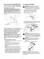
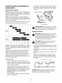
Grounding
TO START THE ENGINE
,_
The Generator
The National Electrical Code requires that the
frame and external electrically conductive parts of
this generator be properly connected to an
approved earth ground. Local electrical codes may
also require proper grounding of the unit. For that
purpose, a grounding lug is provided on the base of
the cradle.
WARNING!devices
Never
start orinto
stop
electrical
plugged
theengine
panel with
receptacles and turned on. You could damage
both the generator and the electrical devices.
•
Unplug all electrical loads from generator
receptacles before starting the engine.
•
Make sure the unit is in a level position.
•
Open the fuel shut-off valve.
_FUEL
TAN_
Pull the choke knob to close. If the engine is warm,
or the ambient temperature is high, pull the choke
knob half-way, or keep it fully open.
Grounding Lug
\
Generally, connecting a No. 12 AWG (American Wire
Gauge) stranded copper wire to the grounding lug and
to an earth-driven copper or brass grounding rod
(electrode) provides adequate protection against
electrical shock. However, local codes may vary
widely. Consult with a local electrician for
grounding requirements in your area.
Proper grounding of generator will help prevent
electrical shock in the event of a ground fault
condition in the generator or in connected electrical
devices. Proper grounding also helps dissipate static
electricity, which often builds up in ungrounded
devices.
Connecting
Electrical
Loads
•
Let engine stabilize and warm up for a few minutes
after starting.
•
Plug in and turn on the desired 120 Volt or
240 Volt, single phase, 60 Hz electrical loads.
Do Not connect 240 Volt loads to 120 Volt
receptacles.
•
•
Do Not connect 3-phase loads to the generator.
•
Do Not connect 50 Hz loads to the generator.
•
Add up the rated watts (or amps) of all loads to be
connected at one time. This total should not be
greater than (a) the rated wattage/amperage
capacity of the generator or (b) circuit breaker
rating of the receptacle supplying the power. See
"Don't Overload the Generator" on page 12.
/
,_
/
/
DANGER!
Engine
exhaust
contains gas
carbon
monoxide, an
colorless
and odorless
which
causes unconsciousness and death. Never run
engine indoors
,_
Close
or in poorly ventilated
areas.
DANGER!
Burn hazard.
Temperature
of
muffler
and nearby
areas may
exceed 150°F
(65°C). Do Not touch these areas on the
generator.
Turn the key switch to the "Start"
position.
IMPORTANT: Do Not operate the electric starter
continuously for more than 5 seconds, even if the
engine does not start. Extended cranking can damage
the starter motor.
NOTE:Ifenginefailsto start,setthe keytothe "Run"
Set the key switch to the "Stop" position after
positionandwaitforabout10secondsbeforeretrying.
stopping the engine. Failure to put the key
switch into the "Stop" position will deplete the
IMPORTANT:
Neverturnthe keyswitchtothe "Start"
battery.
positionwhiletheengineis running.Youcould
damagethestartermotor.
If the Engine Will Not Start
• Whentheenginestarts,graduallyopenchokeby
Perform the following checks if your engine does not
pushingthechokeknobandkeepit fullyopened
start:
whilerunning.
1. Do you have enough gasoline?
Check to make sure you have fuel in the gas tank.
2. Is the fuel valve open?
Check to make sure the fuel valve is open. If it is
closed, open it.
3. Is there enough compression?
Check to see if either spark plug is loose. If so,
tighten it.
4. Is there enough oil?
IMPORTANT:
Do Notoverloadthegenerator!Do Not
overloadindividual
panelreceptacles!
Theseoutlets
areprotected
againstoverloadwithpush-to-reset-type 5.
circuitbreakers.
If amperageratingof anycircuit
•
breakeris exceeded,
thatbreakeropensandelectrical
outputto thatreceptacle
is lost.Read"Don'tOverload
theGenerator"
on page12carefully.
STOPPING
•
THE ENGINE
Unplug (or turn OFF) all electrical loads connected
to generator panel receptacles. Never start or
stop engine with devices plugged in and turned
on.
•
•
•
Let engine run at no-load for 30 seconds to
stabilize the internal temperatures of engine and
generator.
Is the spark plug wet with gasoline?
Apply full choke and crank the engine for 2 or
3 seconds. Remove the plug and check to see if
the electrode is wet. If the electrode is wet, fuel is
well supplied to your engine.
•
If the electrode is dry, check to find where the
fuel is restricted. (Check the fuel intake of the
carburetor and fuel strainer intake.)
•
In case the engine does not start with well
supplied fuel, try using fresh fuel.
6. Is there a strong spark across
_
This procedure eliminates fuel from the carburetor.
Use this method to stop the generator if you plan to
store the generator over a long period. Fuel will clog
the internal passages of carburetor if allowed to
remain for an extended period.
Unplug (or turn OFF) all electrical loads connected
to generator panel receptacles. Never start or
stop engine with devices plugged in and turned
on.
•
Let engine run at no-load for 30 seconds to
stabilize the internal temperatures of engine and
generator.
•
Close the fuel valve while the engine is running
and wait until the engine stops.
the electrode?
ANGER!theWipe
any Place
spilled spark
gasoline
checking
sparkoffplug.
plugbefore
as far
away from the spark plug hole as possible.
Do Not hold spark plug by hand when checking.
Turn the key switch to the "Stop" position.
Close the fuel valve.
STOPPING THE ENGINE WITH THE
FUEL VALVE
•
You unit comes equipped with a low oil pressure
shutdown system. If there is not enough oil in your
engine it will not start. Fill the engine with oil to the
proper level.
•
Remove the spark plug and connect it to the
plug cap. Ground spark plug against engine
body. Turn key switch to "Start" position.
Observe strength of spark.
•
Repeat above step with a new spark plug if
the spark is weak or there is no spark.
•
The ignition system is faulty if there is no
spark with a new spark plug. Take your unit to
your nearest Sears service center.
7. Is your battery well charged?
•
Check the battery as it may be discharged
and unable to operate the electric starter.
Consult your nearest Sears service center.
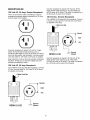
RECEPTACLES
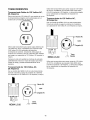
120 Volt AC, 20 Amp, Duplex
Use this receptacle to operate 120 Volt AC, 60 Hz,
single phase loads requiring up to 2,400 watts (2.4
kW) of power at 20 Amps. The outlet is protected by a
20 Amp push-to-reset circuit breaker.
Receptacle
This is a 120 Volt AC outlet, consisting of a pair of
receptacles protected against overload by a 20 Amp
push-to-reset circuit breaker.
120 Volt AC, 30 Amp Receptacle
Use a NEMA L5-30 plug with this receptacle. Connect
a 3-wire cord set rated for 125 Volts AC at 30 Amps
(or greater) to the plug.
3-Wire Cord Set
Neutral
120V
Hot
Use each receptacle to power 120 Volt AC, single
phase, 60 Hz electrical loads requiring up to a
combined 2400 watts (2.4 kW) or 20 Amps of current.
Use only high quality, well-insulated, 3-wire grounded
cord sets rated for 125 Volts at 20 Amps (or greater).
iJ-TG
NEMA L5-30
Use this receptacle to operate 120 Volt AC, 60 Hz,
single phase loads requiring up to 3,600 watts
(3.6 kW) of power at 30 Amps. The outlet is protected
by a 30 Amp push-to-reset circuit breaker.
Keep extension cords as short as possible, preferably
less than 15 feet long, to prevent voltage drop and
possible overheating of wires.
120 Volt AC, 20 Amp Receptacle
Use a NEMA L5-20 plug with this receptacle. Connect
a 3-wire cord set rated for 125 Volts AC at 20 Amps
(or greater) to the plug.
3-Wire Cord Set
Neutral
D
120V
Hot
NEMA L5-20
,_
round
(Green)
Ground
(Green)
10
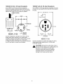
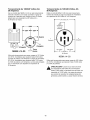
120/240
Volt AC, 30 Amp Receptacle
120/240 Volt AC, 50 Amp Receptacle
Use a NEMA L14-30 plug with this receptacle.
Connect a suitable 4-wire grounded cord set to the
plug and to the desired load. The cord set should be
rated for 250 Volts AC at 30 Amps (or greater).
4-Wire Cord Set
Use a NEMA 14-50 plug with this receptacle. Connect
a 4-wire cord set rated for 250 Volts AC at 50 Amps to
the plug.
240 Volts AC
m
Frame Ground
120V--_
(Neutral)
Y (Hot)
X (Hot)
Y (Hot)
N EMA L14-30
X (Hot)
Ground
(Green)
120 Volts
AC
Use this receptacle to operate 120 Volt AC, 60 Hz,
single phase loads requiring up to 3,600 watts
(3.6 kW) of power at 30 Amps or 240 Volt AC, 60 Hz,
single phase loads requiring up to 7,200 watts
(7.2 kW) of power at 30 Amps. The outlet is protected
by a 30 Amp push-to-reset circuit breaker.
._ q
120 Volts
AC-_
W (Neutral)
NEMA 14-50
Use this receptacle to operate 240 Volts AC, 60 Hz,
single phase loads requiring up to 10,000 watts
(10.0 kW) of power.
CAUTION!
Although
stateswatts),
it has the
a
240 Volt 50 Amp
ratingthis
(upoutlet
to 12,500
generator is only rated for 10,000 watts.
Powering loads that exceed the wattage/
amperage capacity of the generator can
damage it and cause serious injuries.
11
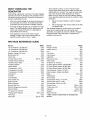
DON'T OVERLOAD
GENERATOR
THE
Overloading a generator in excess of its rated wattage
capacity can result in damage to the generator and to
connected electrical devices. Observe the following to
prevent overloading the unit:
Some electric motors, such as induction types,
require about three times more watts of power for
starting than for running. This surge of power lasts
only a few seconds when starting such motors.
Make sure you allow for this high starting wattage
when selecting electrical devices to connect to your
generator:
•
1.
Figure the watts needed to start the largest
motor.
2.
Add to that figure the running watts of all other
connected loads.
•
•
•
Add up the total wattage of all electrical devices to
be connected at one time. This total should NOT
be greater than the generator's wattage capacity.
The rated wattage of lights can be taken from light
bulbs. The rated wattage of tools, appliances and
motors can usually be found on a data plate or
decal affixed to the device.
The Wattage Reference Guide below is provided to
assist you in determining how many items your
generator can operate at one time. (NOTE: All figures
are approximate. See data plate on appliance for
wattage requirements.)
If the appliance, tool or motor does not give
wattage, multiply volts times ampere rating to
determine watts (volts x amps = watts).
WATTAGE
REFERENCE
GUIDE
Device ..............................
*Air Conditioner (12,000 Btu) ...............
*Air Conditioner (24,000 Btu) ...............
*Air Conditioner (40,000 Btu) ...............
Battery Charger (20 Amp) ..................
Belt Sander (3") .........................
Chain Saw ............................
Circular Saw (6-1/2") ................
*Clothes Dryer (Electric) ..................
*Clothes Dryer (Gas) ......................
*Clothes Washer ........................
Coffee Maker ..........................
Watts
2000
1800
1400
700
700
650
Disc Sander (9") ........................
Edge Trimmer ...........................
Electric Blanket ..........................
Electric Nail Gun ........................
1200
500
400
1200
Electric Range (per element) ...............
Electric Skillet ..........................
1500
1250
Watts
Hedge Trimmer ..........................
Impact Wrench ..........................
Iron ..................................
450
500
1200
*Jet Pump ..............................
Lawn Mower ...........................
800
1200
Light Bulb ..............................
Microwave Oven ...................
*Milk Cooler ............................
Oil Burner on Furnace .....................
800 to 1000
5750
700
1150
1750
*Compressor (1 HP) .....................
*Compressor (3/4 HP) ....................
*Compressor (1/2 HP) ....................
Curling Iron .............................
*Freezer ...............................
*Dehumidifier ...........................
*Furnace Fan (3/5 HP) ....................
*Garage Door Opener ................
Hair Dryer .............................
Hand Drill ........................
Device ..............................
1700
3800
6000
500
1000
1200
100
700 to 1000
1100
300
Oil Fired Space Heater (140,000 Btu) .........
400
Oil Fired Space Heater (85,000 Btu) ..........
225
Oil Fired Space Heater (30,000 Btu) ..........
150
*Paint Sprayer, Airless (1/3 HP) ..............
600
Paint Sprayer, Airless (handheld) ............
150
Radio .............................
50 to 200
*Refrigerator ............................
700
Slow Cooker ............................
200
*Submersible Pump (1-1/2 HP) .............
2800
*Submersible Pump (1 HP) ................
2000
*Submersible Pump (1/2 HP) ...............
1500
*Sump Pump .....................
800 to 1050
*Table Saw (10") ..................
1750 to 2000
Television .........................
200 to 500
Toaster .........................
1000 to 1650
Weed Trimmer ..........................
500
875
500 to 750
1200
250 to 1100
* Allow 3 times the listed watts for starting these
devices.
12
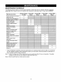
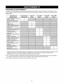
MAINTENANCE
SCHEDULE
The following chart is based on normal engine operation. Follow the hourly or calendar intervals, whichever
occurs first. More frequent service is required when operating in extremely dusty or heavy load conditions.
Maintenance
Items
Clean generator and check
bolts and nuts
Check and refill engine oil
Change engine oil (Note 1)
Clean spark plug
Clean air cleaner
Clean muffler exhaust
outlet
Clean fuel strainer
Replace air cleaner
element
Clean and adjust spark
plugs and electrodes
Replace oil filter
(Note 1)
Clean carburetor*
Clean carbon from cylinder
head*
Clean engine base
(oil pan)*
Check and adjust valve
seats*
Adjust valve clearance*
Replace spark plug
Replace fuel lines*
Overhaul engine*
(Note 2)
*
Every 8 hours
or daily
Every 50
Hours
Every 200
Hours
Every 500
Hours
Every1000
Hours
X
X
X
X
X
X
X
X
X
X
X
X
X
i i i i i i i i i i i i i i i i i i i i i i i i i i i i i i i Xi i i i ii iiiiiiiiiiiiiiiiiiiiiiiiiiiiiiiiiiiiiiiiiiiiiiii
iiiiiiiiiiiiiiii
X
X
!i!i!i!i!i!i!i!i!i!i!i!i!i!i!i!i!i!i!i!i!i!i!i!i!i!i!i!i!i!
X
iiiiiiiiiiiiiiiiiiiiiiiiiiiiiiiiiiiiiiiiiiiiiiiiiiiiiiiiiiiiiiiiiiiiiiiiiiiiiiiiiiiiiiiiiiiiiiiiiiiiiiiiiiiiiiiiiiiii
iiiiiiiiiiiiiiiiiiiiiiiiiiiiiiiiiiiiiiiiiiiiiiiiiiiiiiiiiiiiiiiiiiiiiiiiiiiiiiiiiiiiiiiiiiiiiii
i i'i'i i
X
These maintenance operations should be performed by an authorized Sears service center. If you feel that
you are qualified to perform these maintenance items, you must order a service manual for instructions on
how to properly perform these procedures.
Note 1: Initial oil change and oil filter replacement must be performed after 20 hours of operation. Thereafter
change oil every 50 hours and replace oil filter after 200 hours.
Note 2: Must be performed by a Sears service center.
13
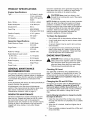
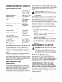
PRODUCT
SPECIFICATIONS
Check the cleanliness of the generator frequently and
clean when dust, dirt, oil, moisture or other foreign
substances are visible on its exterior surface.
Engine Specifications
Type .............................................. Air Cooled, 4 stroke,
V-Twin, Horizontal
Shaft, OHV gasoline
engine
_
CAUTION!
Never
insert
anyeven
objectif the
or tool
through the air
cooling
slots,
engine
is not running.
Gasoline Capacity ......................... 10 U.S. gallons
NOTE: Do Not use a garden hose to clean generator.
Water can enter the engine fuel system and cause
problems. In addition, if water enters the generator
through cooling air slots, some water will be retained
in voids and cracks of the rotor and stator winding
insulation. Water and dirt buildup on the generator
internal windings will eventually decrease the
insulation resistance of these windings.
Oil Type ......................................... See page 7
To Clean the Generator:
Oil Capacity ................................... 1.55 liter
•
Use a damp cloth to wipe exterior surfaces clean.
•
A soft, bristle brush may be used to loosen caked
on dirt, oil, etc.
•
A vacuum cleaner may be used to pick up loose
dirt and debris.
Bore x Stroke ................................ 2-80mm x 65mm
Rated Horsepower ........................ 18 at 3600 rpm
Displacement ................................ 653 cc
Spark Plug .................................... NGK BPR6ES
(Champion RN114C4)
Generator
Specifications
Rated Maximum Power ................ 10,000 Watts
(10.0 kW)
Surge Power ................................. 12,500 Watts
(12.5 kW)
Low pressure
used to blow
and openings
must be kept
Rated AC Voltage ......................... 120/240 Volts
Rated Maximum Load Current:
at 240 Volts ................................. 41.7 Amperes
air (not to exceed 25 psi) may be
away dirt. Inspect cooling air slots
on the generator. These openings
clean and unobstructed.
ENGINE MAINTENANCE
at 120 Volts ................................. 83.3 Amperes
_
Rated Frequency ......................... 60 Hz at 3600 rpm
Phase ............................................ Single Phase
Power Factor ................................. 1.0
GENERAL MAINTENANCE
RECOMMENDATIONS
Checking
Oil Level
See "BEFORE STARTING THE GENERATOR" on
page 7 for information on checking the oil level. The
oil level should be checked before each use, or at
least every eight hours of operation. Keep the oil
level maintained.
The generator warranty does not cover items that
have been subjected to operator abuse or negligence.
To receive full value from the warranty, the operator
must maintain the generator as instructed in this
manual.
Changing
Some adjustments will need to be made periodically to
properly maintain the generator.
the Oil and Oil Filter
Change the oil and filter after the first 20 hours of
operation. Thereafter, change the oil every 50
hours and replace oil filter every 200 hours. If you
are using this engine under dirty or dusty conditions,
or in extremely hot weather, change the oil more
often.
All adjustments in the Service and Adjustments
section of this manual should be made at least once
each season. Follow the requirements in the
"Maintenance Schedule" chart on page 13.
GENERATOR
ANGER!
When working
the generator,
always
disconnect
negative on
cable
from battery.
Also disconnect spark plug wires from spark
plugs and keep wires away from spark plugs.
This will prevent accidental start-up.
MAINTENANCE
Use the following instructions to change the oil while
the engine is still warm:
Generator maintenance consists of keeping the unit
clean and dry. Operate and store the unit in a clean
dry environment where it will not be exposed to
excessive dust, dirt, moisture or any corrosive vapors.
Cooling air slots in the generator must not become
clogged with snow, leaves, or any other foreign
material.
1. Clean the area around the oil drain plug, remove
the plug and drain the oil completely into a suitable
container.
2. When the oil is drained, install and tighten the oil
drain plug.
3. Place a suitable container beneath the oil filter and
remove the filter.
14
4. Coattheo-ringof a newfilterwithengineoil.Turn
the newfilterclockwiseuntilthegasketcontacts
thefilteradapter,thentightenanadditional
2/3turn.
5. Fillenginewithoilas described
on page7.
6. Runtheenginefora minute;stoptheengineand
checkforoilleakagearoundtheoilfilter.Recheck
oillevel.
7. Whenthecrankcaseis filledto theproperlevel,
installandtightentheoilfill cap.
Inspecting
the Spark
Paper Element
•
Clean by tapping gently to remove dirt and blow off
dust. Never use oil. Clean or replace more often in
dirty or dusty environments.
NOTE: If you need to order a new air filter, please call
1-800-336-PART.
Engine
,_
Plugs
Clean spark plugs every 50 hours and replace the
plugs every 500 hours of operation. Use the
recommended spark plugs gapped for 0.6mm to
0.7mm.
1. Stop the engine and pull the spark plug wires off of
the spark plugs.
2. Clean around the spark plugs and remove them
from the cylinder head.
Governed
Speed
CAUTION!
The
engineand
speed
wasrequire
properly
adjusted at the
factory
should
no
additional adjustment. Do Not attempt to
change engine speed. If you believe the engine
is running too fast or too slow, take your unit to
an authorized Sears service center for repair
and adjustment. CHANGING THE ENGINE
GOVERNED SPEED WILL VOID THE ENGINE
WARRANTY.
Do Not try to adjust the governed speed for the
following reasons:
3. Clean off carbon deposits on the spark plug
electrode using a plug cleaner or wire brush.
•
4. Set the spark plugs' gap to 0.6mm to 0.7mm.
Install the correctly gapped spark plugs into the
cylinder heads.
Operating the engine at high engine speeds is
dangerous and increases the risk of personal injury
or damage to the equipment.
•
Operating the engine at low engine speeds with
heavy loads may shorten the engine's life.
Service
Incorrect speed settings also affects electrical
operation of your generator as follows:
Air Cleaner
The engine's air cleaner is one of the most important
areas to maintain. The engine will not run properly and
will be damaged if it is run with a dirty air cleaner
system.
Clean the urethane foam element every 50 hours
of operation. Clean paper element every 50 hours
of operation and replace every 200 hours. Clean or
replace more often in dusty or dirty conditions.
_
•
Operating at high speeds results in an overfrequency and over-voltage condition.
•
Operating at low speeds causes an underfrequency and under-voltage condition.
IMPORTANT:
Incorrect frequency and/or voltage
may damage some connected electrical loads.
If you suspect engine speed is incorrect, take the
unit to an authorized Sears service facility for
repair and adjustment.
CAUTION!
run this
equipment
without
the complete Never
air cleaner
system
installed
on the
engine. Failure to do so will result in premature
engine wear and significantly reduced engine
life.
Carburetor
Adjustments
The engine carburetor is preset at the factory. The
carburetor should not be tampered with because doing
so will void the emission control system warranty. If
you experience problems or your engine is used at an
altitude higher than 5,000 feet, contact the nearest
authorized Sears service center regarding high altitude
setting changes.
The air cleaner paper inner element and urethane
foam outer element can be removed after removing
knob and air cleaner cover. When installing, set the
paper element and urethane foam on the air
cleaner base. Check that the grommet is in
position, and then install the cover with the knob
tightened securely.
Cleaning Urethane Foam Element:
• Wash and clean the urethane foam in kerosene.
Saturate in a mixture of 3 parts kerosene and
1 part engine oil, and then squeeze to remove
excess oil. Clean or replace urethane foam
element every 50 hours (more often in dusty
conditions).
15
GENERAL
•
The generator should be started at least once every
seven days and allowed to run at least 30 minutes. If
this cannot be done and you must store the unit for
more than 30 days, use the following information as a
guide to prepare it for storage.
Cover spark plug holes with rag. Crank the engine
for 2-3 seconds and reinstall the spark plugs.
Do Not connect spark plug wires.
•
Remove the negative battery cable from the battery
to prevent the battery from being depleted.
_
DANGER! Fire, explosion and burn hazard!
The battery is water based. If you are storing the
generator in an area that will go below freezing,
you must remove the battery and store it
separately in an area that will not freeze. If you
allow the battery to freeze, the water in it will
expand and crack open the battery, spilling the
contents. Battery electrolyte fluid is an extremely
caustic sulfuric acid solution that can cause
ANGER!
storepoorly
engineventilated
with fuel areas
in tank
indoors
or inNever
enclosed,
where fumes may reach an open flame, spark or
pilot light as on a furnace, water heater, clothes
dryer or other gas appliance.
LONG TERM STORAGE
It is important to prevent gum deposits from forming in
essential fuel system parts such as the carburetor, fuel
hose or tank during storage. Also, experience
indicates that alcohol-blended fuels (called gasohol,
ethanol or methanol) can attract moisture, which leads
to separation and formation of acids during storage.
Acidic gas can damage the fuel system of an engine
while in storage.
severe burns. The spilled solution may also give
off hydrogen gas, which can ignite at the
slightest spark or flame and cause an explosion.
Clean the generator outer surfaces. Check that
cooling air slots and openings on generator are
open and unobstructed.
Store the unit in a clean, dry, frost-free area.
To avoid engine problems, the fuel system should be
emptied before storage of 30 days or longer, as
follows:
•
_
Remove all gasoline from the fuel tank.
ANGER! away
Drain
fuelopen
into flame.
approved
outdoors,
from
Be container
sure
engine is cool. Do Not smoke.
•
Start and run engine until engine stops from lack of
fuel.
•
While engine is still warm, drain oil from crankcase.
Refill with recommended grade.
•
Remove spark plugs and pour about 1/2 ounce
(15ml) of engine oil into each cylinder.
_
OTHER
AUTION!
Avoid
spray from spark plug hole
when
cranking
engine.
16
STORAGE
TIPS:
•
Do Not store gasoline from one season to another.
•
Replace your gasoline can if the can starts to rust.
Rust and/or dirt in the gasoline will cause
problems.
•
If possible, store your unit indoors and cover it to
give protection from dust and dirt. BE SURE TO
EMPTY THE FUEL TANK.
•
Cover your unit with a suitable protective cover that
does not retain moisture.
_
ANGER!
Never cover
your warm.
generator while
engine
and exhaust
area are
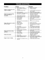
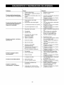
Problem
Engine is running, but no AC
output is available.
Engine runs good but bogs
down when loads are
connected.
Engine will not start; or starts
and runs rough.
Cause
Solution
1.
2.
1.
2.
Reset circuit breaker.
Check and repair.
3.
Circuit breaker is open.
Poor connection or defective
cord set.
Connected device is bad.
3.
4.
1.
2.
Fault in generator.
Short circuit in a connected load.
Generator is overloaded.
4.
1.
2.
3.
4.
1.
2.
3.
Engine speed is too slow.
Shorted generator circuit.
Dirty air cleaner.
Out of gasoline.
Stale gasoline.
3.
4.
1.
2.
3.
4.
Spark plug wire not connected to
spark plug.
Bad spark plug.
Water in gasoline.
Overchoking.
4.
Connect another device that is in
good condition.
Contact Sears service facility.
Disconnect shorted electrical load.
See "Don't Overload the
Generator" on page 12.
Contact Sears service facility.
Contact Sears service facility.
Clean or replace air cleaner.
Fill fuel tank.
Drain gas tank and fill with fresh
fuel.
Connect wire to spark plug.
5.
6.
7.
8. Low oil level.
9. Excessively rich fuel mixture.
10. Intake valve stuck open or
closed.
Engine shuts down during
operation.
Engine lacks power.
Engine "hunts"
or falters.
5.
6.
7.
Replace spark plug.
Drain gas tank; fill with fresh fuel.
Put choke lever to "no choke"
position.
8. Fill crankcase to proper level.
9. Contact Sears service facility.
10. Contact Sears service facility.
3.
1.
Fault in engine.
Load is too high.
11
1.
2.
3.
1.
2.
3.
1.
Dirty air filter.
Engine needs to be serviced.
Choke is opened too soon.
3.
1.
11. Engine has lost compression.
1. Out of gasoline.
2. Low oil level.
.
Carburetor is running too rich or
too lean.
17
.
.
Contact Sears service facility.
Fill fuel tank.
Fill crankcase to proper level.
Contact Sears service facility.
See "Don't Overload the
Generator" on page 12.
Replace air filter.
Contact Sears service facility.
Move choke to halfway position till
engine runs smoothly.
Contact Sears service facility.
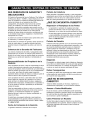
COILI_
CAPACI
TOR
POWER
WI N]]I NG
KEY
SWZTCH
I
13
44
#2
ENG,
I GNZ TI ON
_44D--
SPARK
#[
_'_
120V
I)
20A
20A
C,B,
44A
_A
_.._'_-_J 30 A
ENG,
I GNI TI ON
I _44B-
ii A
_40V_IlB
G
M
B
L
--
T
S
IIA
OFF
ON
$TARG
18
_44A-50A
30A
_'-"o--
oo!
120
840V
30A
I£OV/30A
[
is
16
85
TERMINAL
CONTROL
BLOCK
PANEL
i
85
13
18
13
L3
i
13
16
FU2E
[0 AMP
ts_
x\
I
TD
FRAME
GRDUND
GROUN])
SEARING
3PARK
PLUG
TB REAR
CARRIER
SUPPLIED
BATTERY
19
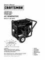
#£
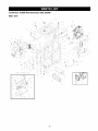
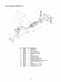
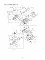
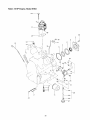
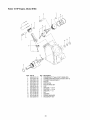
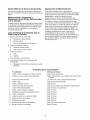
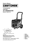
Craftsman
10,000 Watt Generator
580.328300
Main Unit
10
/
/
63
/
37
\
56
55
\\\\
62
29
58
52
\
52
56
61
\\
14
\
3
57
15
65
\
27
\
21
25
Detail
of
Battery
Tray
\\
63
46
5O
43
45
68
\
59
47
2O
15
52
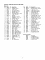
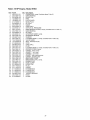
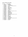
Craftsman
10,000 Watt Generator
580.328300
Main Unit
Item
2
3
4
5
6
7
8
9
10
11
12
PaN#
BB4509
B77304
BB4811
80270
78299
B4325
38353
78831B
B1696
BB4426
83465
Qty
1
2
1
1
1
1
6
4
1
1
4
14
15
16
17
18
19
20
21
22
23
24
25
26
27
28
29
30
32
33
34
36
37
38
39
23152
7
22237
20
22241
10
22746
4
22131
8
BB5228
1
B4425
1
19553621 1
45757
1
B4502
1
22145
2
26850
3
96409
1
B4986
1
92982
1
B4647
1
B4648
1
77816
2
B4826
1
B4824
1
73054
1
B4268
1
BB4481
1
20441
4
40
41
B4489
B4627
1
1
Description
SHIELD, Heat
SUPPORT, Engine
SHIELD, Heat
VALVE, Fuel Shut-Off
BUSHING, Fuel Valve
CAP, Fuel Tank
MOUNTS, Vibration
CAPSCREW, M6-1.0 x 60mm
TANK, Fuel 10 Gal
CRADLE
GROMMET, Fuel Tank
Mounting
CAPSCREW, 3/8-16 x 3/4"
WASHER, 3/8" Lock
NUT, 3/8"-16 Hex
CAPSCREW, 3/8-16 x 1-3/4"
WASHER, 3/8" Flat
SHIELD, Heat
ASSEMBLY, Control Panel
WIRE ASSEMBLY, Ground
HHCS, M6- 1.0 x 25
SWITCH, Key Ignition
WASHER, M8 Flat
WASHER, M6 Shakeproof
DECAL 1-800
DECAL Ground
DECAL Danger
DECAL Side Panel
DECAL Control Panel
DECAL Caution Hot Muffler
DECAL Start Instructions
DECAL Start - Run - Stop
DECAL Fuel Shut-Off
ALTERNATOR, 10KW
GUARD, Muffler
SCREW, 1/4" x 3/4" Self
Driller
BATTERY
KEY, Ignition Switch
Item
42
43
44
45
46
47
48
49
50
51
52
53
54
55
56
57
58
59
60
61
62
63
64
65
66
67
68
69
70
900
PaN#
Qty
BB4682
1
B96925
1
96924
2
19353621 1
19453621 1
52618
2
49226
1
52856
2
49820
2
39253
1
NSP
45771
1
27482
1
47411
2
22473
2
B4948
1
55934G
3
22511
4
B4803
1
52618
1
B4794
1
B2153
20
B4988
1
52857
1
87680
1
B4901
1
23897
2
49813
1
187049
1
NSP
1
Items Not Illustrated
BB3061
2
B3518
1
37806
1
43438
1
93568
1
B4419
1
21
Description
BRACKET, Ignition Switch
BRACKET, Battery Tie Down
J-BOLT, M8 - 1.25
CABLE, Battery Positive
CABLE, Battery Negative
HHCS, M5- 0.8 x 12
WASHER, M5 Lock
NUT, M5 Flange Lock
NUT, Nylok M8- 1.25
CAPSCREW, M8 - 1.25 x 20
SUPPLIED WITH ENGINE
NUT, M8- 1.25
WASHER, 5/16" Shakeproof
CAPSCREW, M6 - 1.0 X 16
WASHER, Flat M6
CLAMP, Hose
CLAMP, Hose
CAPSCREW, 3/8 x 1-1/4"
CONNECTOR, 5-way
HHCS, M5- 0.8 x 12
GROMMET, Generator Cover
SCREW, #12 Self Driller
DECAL, Oil Fill
NUT, Locking M6 - 1.0
WING NUT, M6- 1.0
DECAL, 1-800-4-MyHome
WASHER, M5 Flat
NUT, Hex M6- 1.0
PLUG, Dome, .875 dia.
ENGINE, Robin 18HP
SAE 30 Oil
Oil bottle spout
125 Volt 30 Amp plug
240 Volt 30 Amp plug
125 Volt 20 Amp plug
Owner's manual
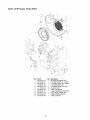
Sincro Alternator
Model
EK-10
/
3
7
\
\\\\
\\\\\
6
16
\\\\
\,
15
Item
1
2
3
4
5
6
7
8
9
10
11
12
13
14
15
16
Pan #
B4906
B4907
B4908
B4909
B4910
B4911
B4912
B4913
B4914
B4915
B4916
B4917
B4918
B4919
B4920
49820
Qty
1
2
1
4
1
1
1
1
2
1
1
1
1
2
8
1
Description
SHIELD, Front
GRID, Front
BOLT, Shaft Stay
STAY BOLT, M8 x 30
ASSEMBLY, Housing
CAP
COVER, Blind End
COVER, Top Black
CAPACITOR, 25mF 450V
BEARING, 62052RS C3
CAPACITOR, Diode + Varistor + EMC
ROTOR (Includes Item 13)
FAN
SCREW, M6- 1.0 x 10mm
SCREW, M5- 0.8 x 10mm
LOCK NUT, M8- 1.25
22
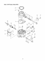
/
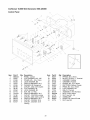
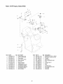
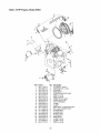
Craftsman
10,000 Watt Generator
580.328300
Control Panel
27
30
31
28
/
25
29
24
\\\
23
\
25
10
21
9
4
10
9
/
9
18
,€
\\\\
2
\4\
5
Item
1
2
3
4
5
6
7
8
9
10
11
12
13
14
15
16
PaN #
BB4504
23897
91526
49226
75207
23365
68759
38150
22264
51715
75207A
74190
68868
B4445
B4262
43437
Qty
1
5
4
5
3
12
1
12
12
12
2
1
1
2
1
1
Item
17
18
19
20
21
22
23
24
25
26
27
28
29
30
31
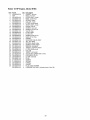
Description
PANEL, Control
FLAT WASHER, #10 - M5
PPHMS, M5- .08 x 12mm
LOCK WASHER, M5
CIRCUIT BREAKER, 20 A
WASHER, #8 Shakeproof
OUTLET, 120V, 20 A Duplex
FLAT WASHER, #8
LOCK WASHER, #8
NUT, M4- 0.7 Hex
CIRCUIT BREAKER, 30 A
OUTLET, 120V/20A Locking
OUTLET, 120V, 30 A Locking
CIRCUIT BREAKER, 45 A
OUTLET, 120/250V, 50 A
OUTLET, 120/240V, 30 A
Locking
23
Part#
80077
92953
90576
84135
75477
B4894
43181
43182
77314
B4737
B95906
51716
B4893
B4892
51714
Qty
4
1
1
1
1
1
4
4
1
1
1
1
2
1
1
Description
PPHMS, M4 x 20mm
BLOCK, 50 Amp, 3 - Terminal
GROMMET, Rubber
GROMMET, Rubber
PPHMS, M5 - 0.8 x 20mm
RECTIFIER, Battery Charge
PHMS, M3- 0.5 x 10mm
LOCK WASHER, M3
RELAY, Thermal
ASSEMBLY, Wire Harness
BOX, Control Panel
NUT, Hex M5- 0.8
STAND OFF
RESISTOR, 2ohm 25 watt
NUT, Hex M3
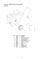
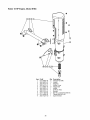
Craftsman
10,000 Watt Generator
580.328300
Wheel Kit
i
\XXxxxxxxxxxx
13
Item
1
2
3
4
5
6
7
8
9
10
11
12
13
14
PaN #
93393B
39287
52858
93394
27007
22145
42909
39253
93693B
89635
89742
22247
87005
22129
Qty
1
4
5
1
1
3
1
2
1
2
2
2
2
2
Description
HANDLE
HHCS, M8- 1.25 x 45
NUT, Locking M8 - 1.25
LEG, Mounting Support
MOUNT, Vibration
FLAT WASHER, 5/16 - M8
HHCS, M8- 1.25 x 30
HHCS, M8- 1.25 x 20
AXLE
SPACER, Wheel
WHEEL
WASHER, Wheel
PIN, Retaining
WASHER, M8 Lock
24
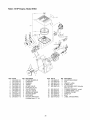
Robin 18 HP Engine, Model
Item
1
2
3
4
5
6
7
8
9
10
11
12
Pa_ #
263-33001-03
263-31A01-03
020-02000-10
246-33301-03
263-33401-03
263-33501-03
263-33601-03
246-35501-03
246-33711-03
239-35001-03
263-35302-03
246-36101-10
Qty
1
1
4
4
2
2
4
8
4
2
4
4
EH63
Description
INTAKE MANIFOLD
CAMSHAFT
WASHER
TAPPET
INTAKE VALVE
EXHAUST VALVE
VALVE SPRING
COLLET- VALVE
SPRING RETAINER
ROCKER SHAFT
PUSH ROD
ROCKER ARM ASSY
(Includes items 13 - 14)
25
Item
13
14
15
16
17
Part#
014-90800-21
017-00800-90
246-35201-03
002-38080-00
263-32601-00
Qty
4
4
2
4
1
18
19
20
21
22
23
263-32610-01
263-32620-01
263-32630-03
263-32640-01
Xll-60500-20
263-91703-03
1
1
1
1
3
1
Description
ADJUSTING SCREW
NUT
GASKET, muffler
FLANGE NUT
AIR CLEANER ASSY (Includes
items 18 - 21)
CLEANER ELEMENT, compl.
CLEANER BASF, compl.
CLEANER COVER
WING NUT
BOLT
LABEL (TRADE MARK)
Robin 18 HP Engine, Model
EH63
3O
29
4t
24
24
25
39
26
\
I
\
6
15
28
11
26
Robin 18 HP Engine, Model
Item
1
2
3
4
5
6
7
8
9
10
11
12
13
14
15
16
17
18
19
20
21
22
23
24
25
26
27
28
29
30
31
32
33
34
35
36
37
38
39
40
41
42
Part #
263-10101-01
263-15801-03
005-26081-80
142-55601-03
159-65401-03
212-15008-13
044-00800-10
263-15901-03
045-01200-10
248-76301-01
263-11102-01
263-15801-03
044-04200-10
263-45001-01
263-41901-03
263-46214-A3
263-13001-01
132-12AA0-80
132-07AA0-50
010-50802-90
006-90104-00
263-16201-03
263-13101-01
246-15501-01
246-16002-13
263-15001-03
263-15101-03
263-16001-03
263-16006-03
263-14301-03
263-14401-01
263-18001-03
263-68511-03
031-00600-20
040-11400-30
021-11400-20
011-01000-30
011-00800-90
011-00600-30
263-46213-A3
263-19001-03
214-79006-01
Qty
1
1
2
2
1
1
1
1
1
1
1
1
1
1
1
1
1
4
2
8
1
1
1
2
2
1
1
1
2
1
1
1
2
4
2
2
8
10
10
1
2
1
EH63
Description
CRANKCASE, compl. (Includes items 2 thru 9)
MAIN BEARING
DOWEL PIN
PIPE
PIPE (PULSE)
BLIND PLUG
OIL SEAL
UNION
STEEL BALL
SWITCH OIL PRESSURE
MAIN BEARING COVER, compl. (Includes items 12 and 13)
MAIN BEARING
OIL SEAL
GOVERNOR GEAR, compl.
GOVERNOR SLEEVE
WASH ER
CYLINDER HEAD 1, compl. (Includes items 18 thru 22)
VALVE GUIDE
SEAL-INTAKE VALVE
STUD
STEEL BALL
PLUG
CYLINDER HEAD 2, compl. (Includes items 18 thru 21)
ROCKER COVER, compl.
GASKET, rocker cover
GASKET 1, cyl. head
GASKET 2, cyl. head
GASKET, main bearing cover
GASKET, breather plate
BREATHER COVER
BREATHER PLATE, compl.
RUBBER PIPE
HOSE CLAMP
DOWEL PIN
PLUG
GASKET
FLANGE BOLT
FLANGE BOLT
FLANGE BOLT
THRUST BEARING
HOOK
CLAMP
27
Robin 18 HP Engine, Model
EH63
22
j
.4
e_2_
I
I
t8
Item
1
2
3
4
5
6
7
8
9
10
11
12
13
Part #
263-46001-03
263-46011-01
263-43901-01
263-46010-03
261-45201-03
261-43101-03
003-22100-00
015-20500-10
263-42301-03
263-42201-03
263-42505-03
263-42701-01
263-42801-03
Qty
1
1
1
1
2
1
1
1
1
1
1
1
1
Item
14
18
19
20
21
22
23
24
25
26
27
28
29
Description
Choke Control Link
Choke Control Rod
Choke knob
Choke Knob Clamp
Return Spring
Link Pivot
Waved Washer
Tapping Screw
GOVERNOR LEVER
GOVERNOR SHAFT
GOVERNOR SPRING
GOVERNOR ROD
ROD SPRING
28
Part#
263-43311-A3
263-45021-A2
261-43901-03
005-11060-00
001-14063-00
018-60600-20
011-00600-20
011-50500-20
002-27050-00
002-38060-00
001-17052-00
003-10080-00
X23-00801-50
Qty
1
1
2
1
1
1
2
1
1
1
1
1
1
24
Description
SPEED CONTROL LEVER
BRACKET, Speed Control
CLAMP
SNAP PIN
BOLT/WASHER ASSY
NUT
FLANGE BOLT
BOLT
NUT
FLANGE NUT
BOLT/WASHER ASSY
WASHER
SPACER
Robin 18 HP Engine, Model
EH63
6
10
6
\
\
\
6
5
Item
1
2
3
4
5
6
7
8
9
10
11
Pa_ #
263-51101-02
263-52601-01
263-52701-01
263-52801-03
263-52911-A2
011-00600-20
263-92001-03
263-95201-03
263-54101-02
263-91803-03
263-95301-A3
29
Qty
1
1
1
1
1
19
1
1
1
1
1
Description
BLOWER HOUSING UNIT
CYLINDER BAFFLE I COMPL.
CYLINDER BAFFLE 2 COMPL.
CYLINDER BAFFLE 3
CYLINDER BAFFLE 4 UNIT
FLANGE BOLT
LABEL (WARNING)
LABEL (EMISSION CONTROL)
COOLING BLOWER UNIT
LABEL (ENGINE NAME)
LABEL (CHOKE)
Robin 18 HP Engine, Model
EH63
23
3O
Robin 18 HP Engine, Model
Item
1
2
3
4
5
6
7
8
9
10
11
12
13
14
15
15
16
17
18
19
20
21
21
22
23
24
25
26
27
28
28
29
30
31
Pa_ #
263-63901-03
263-63902-03
263-64301-02
263-64001-01
044-03500-90
X24-08900-20
263-65001-13
003-70140-00
248-65601-03
006-90308-00
261-65902-A0
263-63602-A1
263-63602-03
021-31600-10
263-62601-01
263-68001-03
263-68501-03
263-62501-00
263-66201-03
248-62201-00
263-65002-02
263-62650-01
263-68051-03
263-68501-03
Xll-60500-20
011-00801-10
011-00601-40
011-00600-20
263-65011-A0
263-62611-A1
263-68002-03
263-68501-03
160-67402-A3
206-75501-01
Qty
1
1
1
1
1
1
1
1
1
1
1
1
1
1
1
1
2
1
1
1
1
1
1
2
1
2
4
4
1
1
1
2
1
2
EH63
Description
INNER ROTOR
OUTER ROTOR
OIL PUMP FILTER UNIT
OIL PUMP COVER, compl. (Includes item 5)
OIL SEAL
O-RING
PLUG, oil relief
GASKET, aluminum
SPRING, relief valve
STEEL BALL
OIL FILTER
OIL GAUGE, compl.
OIL FILL CAP
GASKET
FUEL PIPE, compl. (Includes items 15 and 16)
RUBBER PIPE
HOSE CLAMP
CARBURETOR ASSY
GASKET, carburetor
FUEL PUMP ASSY
BRACKET, fuel pump
PULSE PIPE, compl. (Includes items 21 and 22)
RUBBER PIPE
HOSE CLAMP
BOLT
FLANGE BOLT
FLANGE BOLT
FLANGE BOLT
FUEL FILTER ASSY
FUEL PIPE COMPL. (Includes items 28 and 29)
RUBBER PIPE
HOSE CLAMP
VINYL PIPE
CLAMP CP
31
Robin 18 HP Engine, Model
EH63
32
Robin 18 HP Engine, Model
Item
2
3
4
5
6
7
8
9
10
11
12
13
14
15
16
17
18
19
20
21
22
23
24
25
26
27
28
29
30
31
32
33
34
35
36
Pa_ #
258-62545-08
NSP
263-62524-08
258-62551-08
263-62445-08
258-62553-08
258-62554-08
263-62520-08
258-62525-08
258-62555-08
258-62450-08
226-62501-08
258-62505-08
258-62515-08
258-62556-08
263-62400-08
258-62546-08
258-62557-08
263-62421-08
258-62445-08
258-62451-08
261-62435-08
263-62530-08
226-62580-08
258-62570-08
263-62535-08
261-62352-08
258-62560-08
258-62566-08
263-62551-08
215-62353-08
215-62446-08
263-62560-08
263-62555-08
263-62570-08
263-62503-00
Qty
1
1
1
1
1
1
1
1
1
2
4
1
1
1
1
1
1
1
1
1
1
1
1
1
1
1
2
1
1
1
1
1
1
1
1
0
EH63
Description
GASKET, air horn
BODY, Air Horn
LEVER ASSY, choke
RING, choke lever
SPRING, choke
COLLAR, choke
FILTER, choke shaft
SHAFT ASSY, choke
CHOKE VALVE
SCREW, valve set
SCREW, air horn set
VALVE, float
FLOAT ASSY
FLOAT PIN
SCREW, float pin set
MAIN JET (# 134)
GASKET
SOLENOID VALVE ASSY
JET, slow (#58)
SPRING, adjust screw
SCREW, throttle adjust
NEEDLE, idle adjust
THROTTLE SHAFT ASSY
FILTER throttle shaft
COLLAR
THROTTLE VALVE
VALVE SET SCREW (M3 x 5mm)
EXPANSION PLUG
CLAMP, solenoid
PLUG
SCREW
SPRING
O-RING
GASKET
PLUG, ANTI TAMPER
CARBURETOR ASSY (Includes items 2 thru 36)
33
Robin 18 HP Engine, Model
EH63
7
\
7
\
Item
1
2
3
4
5
6
7
8
8
8
9
10
11
12
Pa_ #
263-21201-01
263-22501-00
246-23001-03
263-23401-03
263-23301-03
263-23501-07
056-52100-20
263-25001-03
263-25002-03
263-25003-03
002-18180-00
003-10180-00
003-20180-00
005-32054-01
Qty
1
2
2
2
2
2
4
1
1
1
1
1
1
1
Description
CRANKSHAFT, Taper 2.25/12 (SAE-WG)
CONNECTING ROD ASSY (Includes item 3)
CONNECTING ROD BOLT
PISTON
PISTON PIN
PISTON RING SET
CLIP
SPACER, t = 0.6 or
SPACER, t = 0.8 or
SPACER, t = 1.0
NUT
WASHER
SPRING WASHER
WOODRUFF KEY
34
Robin 18 HP Engine,
Model
EH63
25
24
Item
1
2
4
5
6
8
9
10
11
12
13
17
20
21
23
24
25
27
29
30
31
33
Pa_ #
263-77202-01
263-78201-01
246-79501-03
263-71001-03
263-70502-A0
263-73016-01
263-73017-01
065-01404-80
065-50001-40
065-90000-10
206-75501-01
056-60002-50
263-73102-A1
001-14063-00
Xll-00801-00
Xll-00600-20
263-55001-A3
002-38080-00
056-30000-40
206-75501-01
214-79006-01
263-73112-01
Qty
1
2
2
1
1
I
I
2
2
2
1
3
1
4
2
4
1
2
4
1
1
1
35
Description
FLYWHEEL, compl.
IGNITION COIL, compl.
GROMMET
RING GEAR
STARTING MOTOR ASSY
WIRE 4, compl.
WIRE 5, compl.
SPARK PLUG, compl.
SPARK PLUG CAP
PLUG TERMINAL
CLAMP
CLAMP
WIRE ASSY, oil pressure switch
BOLT and WASHER ASSY
FLANGE BOLT
FLANGE BOLT
BLIND PLATE
FLANGE NUT
WIRE BAND
CLAMP, compl.
CLAMP, compl.
WIRE 6, compl.
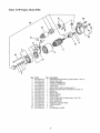
Robin 18 HP Engine, Model
EH63
O
O
Item
1
2
3
4
5
6
7
8
9
10
11
Pa_#
017-00800-30
263-35201-A1
263-34101-A1
263-34211-01
011-00600-10
263-30201-01
263-37301-A1
263-37011-A1
001-11081-60
001-04085-05
263-37321-A2
36
Qty
6
3
1
1
8
1
1
1
2
1
1
Description
Flanged Nut (M8)
Gasket
Manifold
Muffler Cover
Flange Bolt
Muffler
Deflector Ass'y
Bracket
Bolt W/Lockwasher (M8x16)
Flange Bolt (M8 x 50
Spark Arrester
Robin 18 HP Engine, Model
EH63
1'7
20
16
18
15
13
8
12
4
2
lg
\
10
3
Item
1
2
3
4
5
6
8
9
10
11
12
13
16
17
18
19
20
21
Part#
263-70502-A0
263-70510-08
263-70550-08
210-70534-08
255-70580-08
263-70505-08
255-70531-08
228-70514-08
255-70551-08
228-70516-08
255-70521-08
263-70500-08
255-70570-08
243-70525-08
263-70515-08
207-70524-08
263-70551-08
263-70552-08
Qty
1
1
1
1
1
1
1
2
1
4
I
1
1
1
1
2
2
1
Description
STARTING MOTOR ASSY (Includes items 1 thru 21)
ARMATURE ASSY
THRUST WASHER KIT
PINION STOPPER SET
YOKE ASSY
REAR COVER ASSY (Includes item 7)
BRUSH HOLDER ASSY (Includes items 9 thru 11)
BRUSH (-)
BRUSH SET
BRUSH SPRING
PINION ASSY
GEAR CASE ASSY (Includes items 14 and 15)
DUST COVER KIT
SHIFT LEVER KIT
MAGNETIC SWITCH ASSY
THROUGH BOLT
BOLT
M TERMINAL COVER
37
YOUR WARRANTY
OBLIGATIONS
RIGHTS AND
WHAT IS COVERED
Repair or Replacement
The California Air Resources Board ("CARB") and
Sears Roebuck and Co., USA, are pleased to explain
the Emission Control System Warranty on your model
year 2000 and later small off-road engine (engine). In
California, new engines must be designed, built and
equipped to meet the State's stringent anti-smog
standards. Sears must warrant the emission control
system on your engine for the periods of time listed
below provided there has been no abuse, neglect, or
improper maintenance of your engine.
Coverage
Warranty
Responsibilities
Damages
Sears may be liable for damages to other engine
components caused by the failure of a warranted part
still under warranty.
WHAT IS NOT COVERED
All failures caused by abuse, neglect, or improper
maintenance are not covered.
Add-on
or Modified
Parts
The use of add-on or modified parts can be grounds
for disallowing a warranty claim. Sears is not liable to
cover failures of warranted parts caused by the use of
add-on or modified parts.
You are responsible for presenting your engine to a
Sears authorized repair center as soon as a problem
exists. Warranty repairs should be completed in a
reasonable amount of time, not to exceed 30 days.
How to File a Claim
If you have any questions regarding your warranty
rights and responsibilities, you should contact your
nearest authorized service center or call Sears at
1-800-473-7247.
If you have any questions regarding your warranty
rights and responsibilities, you should contact your
nearest authorized service center or call Sears at
1-800-473-7247.
Where
Date
to Get Warranty
Service
Warranty services or repairs shall be provided at all
Sears authorized service centers.
The warranty period begins on the date of sale.
Length
Period
Consequential
As the engine owner, you should be aware that Sears
may deny you warranty coverage if your engine or a
part of it has failed due to abuse, neglect, improper
maintenance, unapproved modifications, or the use of
parts not made or approved by the original equipment
manufacturer.
Commencement
If you have any questions regarding your warranty
rights and responsibilities, your should contact your
nearest authorized service center or call Sears at
1-800-473-7247.
The owner shall not be charged for diagnostic labor
which leads to the determination that the warranted
part is defective if the diagnostic work is performed at
an approved Sears service center.
As the engine owner, you are responsible for the
performance of the required maintenance listed in this
owners manual. Sears recommends that you retain all
receipts covering maintenance on your engine, but
Sears cannot deny warranty solely due for the lack of
receipts or for your failure to ensure the performance
of all scheduled maintenance.
Warranty
•
Diagnosis
The model year 2000 and later engines are warranted
for two years. If any emission related part on your
engine (as listed below) is defective, the part will be
repaired or replaced by Sears.
Owner's
Repair or replacement of any warranted part will be
performed at no charge to the owner at an
approved Sears service center.
Any warranted part which is not scheduled for
replacement as required maintenance, or which is
scheduled only for regular inspection to the effect of
"repair or replace as necessary" shall be warranted for
two years. Any warranted part which is scheduled for
replacement as required maintenance shall be
warranted for the period of time up to the first
scheduled replacement point for that part.
Where a warrantable condition exists, Sears will repair
your engine at no cost to you. Expenses covered
under under warranty include diagnosis, parts, and
labor.
Warranty
•
Warranty
Your emission control system includes parts such as
the carburetor and the ignition system.
Manufacturer's
of Parts
Maintenance,
Replacement
Emission Related Parts
of Coverage
Sears warrants to the initial owner and each
subsequent purchaser that the engine is free from
defects in materials and workmanship which cause the
failure of a warranted part for a period of two years.
and Repair of
Any Sears approved replacement part used in the
performance of any warranty maintenance or repair on
emission related parts will be provided without charge
to the owner if the part it under warranty.
38
Emission
Control
Warranty
Maintenance
Parts List
1. Fuel Metering System
a.
Carburetor and internal parts
b.
Choke system
c.
Fuel strainer, if applicable
It is your responsibility to have all scheduled
inspection and maintenance services performed at the
times recommended in the 1998 and later owner's
manual and to retain proof that inspection and
maintenance service are performed at the times when
recommended. Sears will not deny a warranty claim
solely because you have no record of maintenance;
however Sears may deny a warranty claim if your
failure to perform required maintenance resulted in the
failure of a warrantedpart. The proof which you
maintain should be given to each subsequent owner of
the engine. You are responsible for performing the
scheduled maintenance described below based on the
procedures specified in the owner's manual. The
scheduled maintenance below is based on the normal
engine operating schedule:
2. Air Induction System
a.
Air filter element
b.
Intake pipe, if applicable
3. Ignition System
a.
Spark plug
b.
Magneto
4. Exhaust Pipe, if applicable
5. Miscellaneous
a.
Statements
Items Used in Above Systems
Fuel hoses, clamps, and sealing gaskets
Maintenance
Schedule
Procedure
Interval
1)
Clean engine and check bolts & nuts
Every 8 hours (daily)
2)
Check and refill engine oil
Every 8 hours (refill daily up to upper limit)
3)
Change engine oil
Initial 20 hours and every 50 hours afterward
4)
Clean spark plug
Every 50 hours (weekly)
5)
Clean air cleaner
Every 50 hours
6)
Check muffler exhaust outlet
Clean if necessary every 50 hours (monthly)
7)
Clean fuel strainer
Every 200 hours (monthly)
8)
Clean and adjust spark plug and electrodes
Every 200 hours
9)
Replace air cleaner element
Every 200 hours
10)
Clean carburetor
Every 500 hours
11)
Clean carbon from cylinder head
Every 500 hours
12)
Adjust valve clearance
Every 500 hours
13)
Replace spark plugs
Every 500 hours
14)
Replace fuel lines
Every 1000 hours (yearly)
15)
Overhaul engine if necessary
Every 1000 hours
39
Garantia................................
ReglasdeSeguridad.......................
Montaje..............................
Funcionamiento
........................
Mantenimiento
.........................
GARANTIA
LIMITADA
40
41
42-43
44-50
51-53
Especificaciones
delProducto................
52
Almacenamiento
..........................
54
Reparacion
deAverias.....................
55
GarantiadeEmisiones...................
56-57
ComoOrdenarPartes.............
UltimaPagina
PARA GENERADORES
PORTATILES
DE LUJO
SEARS le garantiza al comprador original que el alternador y el motor de su generador portatil estara libre de defectos en
materiales y mano de obra en los componentes y por el periodo de tiempo establecido a continuaci6n a partir de la fecha de
compra original. Esta garantia no es transferible.
CLIENTE*
COMERCIAL*
Alternador
1 afio trabajo, 2 afios partes
1 afio trabajo y partes
Motor
1 afio trabajo, 2 afios partes
1 afio trabajo y partes
* NOTA: Para prop6sitos de esta garantia el t6rmino "Uso del Cliente" representa el uso dom6stico residencial y de
emergencia por parte del comprador original, sin incluir aplicaciones donde la unidad sea usada como fuente de potencia
principal. El t6rmino "Uso Comerciar' representa todos los otros usos, incluyendo alquiler, construcci6n, comercial y para
prop6sitos lucrativos. Una vez el generador haya tenido uso comercial, 6ste sera considerado como un generador para uso
comercial para los fines de esta garantia.
Durante dicho periodo de garantia, SEARS reparara o reemplazara, a su discreci6n, cualquier parte que haya sido
encontrada defectuosa, en examen previo realizado por SEARS, bajo uso y servicio normal**. Las baterias de arranque no
estan garantizadas por SEARS. Todos los costos de transporte bajo garantia, incluyendo el envio a la fabrica, de ser
necesario, seran responsabilidad del comprador y deberan ser pagados por anticipado. Esta garantia no cubre el
mantenimiento y servicio normal y no se aplica a juegos de generadores, alternador, motor o partes que hayan sido sujetos
a instalaciones o modificaciones incorrectas o no autorizadas, mal uso, negligencia, accidente, sobrecarga, exceso de
velocidad, mantenimiento, reparaci6n o almacenamiento incorrecto que, a juicio de SEARS, afecte negativamente su
funcionamiento y confiabilidad.
** DESGASTE NORMAL: Como con todos los dispositivos mecanicos, los motores necesitan el servicio y reemplazo
peri6dico de las partes para funcionar en buenas condiciones. Esta garantia no cubre reparaciones cuando el uso normal
haya sobrepasado la vida etil de una parte o motor.
NO EXISTEN OTRAS GARANTIAS EXPRESAS. SEARS POR MEDIO DE LA PRESENTE DESCONOCE TODAS LAS
GARANTIAS IMPLICITAS, INCLUYENDO, SIN LIMITARSE, A AQUELLAS DE COMERCIALIZACION Y ADAPTACION
PARA UN PROPOSITO PARTICULAR AL EXTREMO PERMITIDO POR LA LEY. LA DURACION DE CUALQUIER
GARANTIA IMPLICITA QUE NO PUEDA SER DESCONOCIDA, ESTA LIMITADA AL PERIODO DE TIEMPO
ESPECIFICADO EN LA GARANTIA EXPRESA. LA RESPONSABILIDAD
LEGAL ES EXCLUIDA POR DANOS
CONSECUENCIALES,
INCIDENTALES O ESPECIALES BAJO CUALQUIERA DE LAS GARANTIAS.
Algunos estados no permiten limitaciones en la duraci6n de las garantias implicitas, o la exclusi6n o limitaci6n de daSos
incidentales o consecuenciales, por tanto las limitaciones o exclusiones anteriormente mencionadas podrian no aplicarse a
usted. Esta garantia le otorga derechos legales especificos; usted podria tener otros derechos, los cuales cambian de
estado a estado.
Para servicio, visite su centro de servicio de garantia autorizado SEARS mas cercano. El servicio de garantia puede ser
Ilevado a cabo Qnicamente por un centro de servicio autorizado SEARS. Esta garantia no se podra aplicar para servicio en
otros centros de servicio. Evidencia de la fecha de compra original debera ser presentada en el momento de solicitar el
servicio de garantia.
Sears, Roebuck
and Co., D/817WA,
40
Hoffman
Estates,
IL 60179
recubrimiento, etc. Nunca permita que personas no
calificadas operen o proporcionen servicio al generador.
iPRECAUCION!
Lea este manual y siga todas las
•
Nunca manipule dispositivos o cordones el6ctricos
cuando se encuentre parado en agua, descalzo o con los
pies o las manos mojadas. Podrian ocurrir descargas
el6ctricas peligrosas.
•
Use un interruptor de circuito de falla a tierra en areas
h6medas o de alta conductividad (como en pisos
metalicos o estructuras de acero).
•
No utilice en el generador juegos de cordones el6ctricos
que est6n desgastados, pelados, raidos o daSados de
cualquier manera. El uso de juegos de cordones
el6ctricos defectuosos puede ocasionar descargas
el6ctricas o daSos al equipo y/o a la propiedad.
•
Opere el generador 6nicamente en superficies niveladas
y donde no se vaya a exponer a humedad excesiva,
suciedad, polvo o vapores corrosivos.
•
La gasolina es altamente INFLAMABLE y sus vapores
son EXPLOSIVOS. No permita que fumen, que existan
llamas abiertas, chispas o calor a su alrededor cuando
manipule gasolina. Evite regar gasolina sobre motores
calientes. Cumpla con todas las regulaciones que
requieran almacenamiento y manejo de gasolina.
•
Nunca almacene el generador con combustible en el
tanque, donde los vapores de la gasolina puedan entrar
en contacto con llamas abiertas, chispas o luces de piloto
(como en hornos, calentadores de agua o secadoras de
ropa). Podrian ocurrir INCENDIOS o EXPLOSIONES.
•
Nunca agregue combustible cuando la unidad est6 en
funcionamiento.
•
No Ilene el tanque de combustible excesivamente.
Siempre permita que exista espacio para la expansi6n
del combustible. Si el tanque esta demasiado Ileno, el
combustible podria rebosarse y caer sobre el motor
caliente y ocasionar un INCENDIO o una EXPLOSION.
•
Nunca arranque o detenga el motor-generador cuando
tenga cargas el6ctricas conectadas a los tomacorrientes
y los dispositivos conectados est6n ENCENDIDOS.
Arranque el motor y permita que se estabilice antes de
conectar las cargas el6ctricas. Desconecte todas las
cargas el6ctricas antes de apagar el generador.
•
No introduzca objetos a trav6s de las ranuras de
enfriamiento del motor-generador.
Reglas de Seguridad e Instrucciones de Operaci6n
antes de usar este producto.
iPELIGRO!
Debera aislar el generador del servicio
el6ctrico abriendo el cortacircuito principal o
interruptor principal del sistema el6ctrico si la unidad
va a ser usada como alimentaci6n de reserva. Si no
aisla el generador del servicio el_ctrico podrian
ocurrir lesiones, muerte de los trabajadores
del
servicio de electricidad
o daSos al generador.
iPELIGRO!
Los gases del escape del generador
contienen gas de mon6xido de carbono MORTAL. Si
el mon6xido de carbono se inhala en
concentraciones suficientes, puede ocasionar p6rdida
de la consciencia o incluso la muerte. Unicamente
opere este equipo al aire libre donde exista
ventilaci6n adecuada.
iPRECAUCION!
Siempre desconecte el alambre
de la bujia y col6quelo donde no pueda entrar en
contacto con la bujia, para evitar el arranque
accidental durante la instalaci6n, transporte, ajuste o
reparaci6n de su generador.
°
•
Nunca opere el generador:
en la Iluvia; en compartimientos encerrados; si se
recalientan los dispositivos el6ctricos conectados; si se
pierde la salida el6ctrica; si se presentan chispas en el
motor o generador; si se observan llamas o humo cuando
la unidad esta funcionando; si la unidad vibra
excesivamente.
El motor-generador requiere de una circulaci6n de aire de
enfriamiento adecuada para un funcionamiento continuo
y adecuado. Nunca opere la unidad en el interior de
habitaciones o recintos encerrados donde la circulaci6n
de aire de enfriamiento que entra o sale de la unidad
pueda ser obstruida. Deje por Io menos 3 pies de
distancia alrededor del generador, incluso cuando la
unidad est6 funcionando en exteriores, de otra forma
podria daSar la unidad.
•
,_
NOTA: Su generador esta equipado con un silenciador
apagachispas. El apagachispas debera ser mantenido en
buenas condiciones de trabajo por parte del
propietario/operador. La ley en el Estado de California exige
el uso del apagachispas (Secci6n 4442 del C6digo de
Recursos P6blicos de California). Otros estados pueden
tener leyes similares. Las leyes federales se aplican en
tierras federales.
El generador produce un voltaje muy alto, el cual puede
ocasionar descargas el6ctricas extremamente peligrosas.
Evite el contacto con terminales, alambres pelados o sin
BUSQUE
ESTE iESTE
SIMBOLO
PARA SU
SENALAR
PRECAUCIONES
DE SEGURIDAD
"iATENCION!!!
ALERTA!!!
SEGURIDAD
ESTA EN PELIGRO."
41
IMPORTANTES.
ESTE SIGNIFICA
Sugenerador
requiere
deciertoensamble
yestaralisto
REVISE LA BATERIA / CONECTE
paraserusadodespu6s
dehaberle
dadounservicio
adecuado
conelaceite
y elcombustible
recomendados. ALAMBRE NEGATIVO DE LA
BATERIA
Sitieneproblemas
conelmontaje
desugenerador,
por
favorIlamealaLineadeAyuda
delGenerador
al
La bateria del generador se encuentra completamente
1-800-222-3136.
cargada, sellada y ha sido previamente instalada con la
excepci6n del cable negativo (negro) de la bateria
IMPORTANTE: Cualquier intento de poner en marcha al
motor antes de darle el servicio con el aceite recomendado
resultara en falla del motor
PARA RETIRAR
DE LA CAJA
Coloque la caja entarimada sobre una superficie plana y
rigida
•
Corte con cuidado las bandas que estan alrededor de la
caja de envio
•
Levante la caja del generador
•
Retire todo el material de protecci6n, material de relleno,
etc
•
Retire el generador de la tarima de envio
CONTENIDO
Para instalarlo:
EL GENERADOR
•
•
Retire la tuerca del terminal negativo de la bateria
•
Inserte el cable negativo de la bateria en el tornillo del
terminal
\
DE LA CAJA
Revise todo el contenido. Si alguna parte falta o esta
daSada, Ilame a la Linea de Ayuda del Generador al
1-800-222-3136.
La caja incluye:
• Generador de 10000 Vatios
•
•
•
Manual del Propietario
2 Botella de Aceite para Motor (28 oz)
Enchufe de 125 Voltios, 30 Amperios
•
•
•
•
Enchufe de 125 Voltios, 20 Amperios
Enchufe de 240 Voltios, 30 Amperios
Embudo para Llenado de Aceite
Juego de Ruedas
EL
42
•
Vuelva a enroscar la tuerca y apriete
•
Asegt_rese de que las conexiones en la bateria y el
generador se encuentre apretadas y seguras
INSTALACION
RUEDAS
DEL JUEGO DE
NOTA: Aseg6rese de instalar la rueda con la parte
levantada de la maza hacia adentro.
5. Instale la otra rueda de la misma forma.
6. Asegure el montaje antivibratorio a la pata de soporte
con la tuerca de sujeci6n y el tornillo prisionero largo de
30 mm. Ajuste la pata de soporte a la parte inferior del
bastidor del generador utilizando dos tornillos prisioneros
de 20 mm y dos arandelas y dos arandelas plana.
Para instalar su juego de ruedas, necesitara las
siguientes herramientas:
•
Llave de cubos o extremo abierto m6trica de 13mm.
Instale el Juego de Ruedas como se describe a
continuacion:
7. Coloque la manija por debajo de la m6nsula del
silenciador en el lado del motor del generador. Instale la
manija con cuatro tornillos prisioneros largos de 45 mm y
cuatro tuercas de sujeci6n.
1. Coloque la parte inferior del bastidor del generador sobre
una superficie plana y pareja.
2.
Pase el eje a trav6s de ambas m6nsulas de montaje del
armaz6n del bastidor.
8. Vuelva a revisar todas las tuercas para asegurarse de
que estan apretadas correctamente.
3. Inserte un espaciador en cada extremo del eje.
4.
Instale la rueda. Asegure la rueda al eje con el pasador
de retenci6n y la arandela.
Manija
Tuerca de
Sujeci6n
,/
/
/
/
Tornillo Prisionero
de 45 mm
/
\Tuerca de
Sujecidn
._
_
Soporte
'
"__
f
Eje
Pata de
Antivibratorio
Espaciador
Montaje
f"
/
/
Rueda
_/
Arandela
/
Pasador de
Retenci6n
43
__
Arandela
Plana M8
_,randela
_ _randela
_ Tornillo
_--Prisionero
Tornillo
Prisionero
de 20 mm
de 30 mm
Plana
CONOZCA
SU GENERADOR
Lea este manual del propietario y las reglas de seguridad antes de operar su generador.
Compare las ilustraciones con su generador para familiarizarse con la ubicaci6n de los diferentes controles y ajustes.
Valvula de Corte de
ue de Combustible
Filtro de Aire
(en la parte
superior del
motor)
Cortacircuitos
(AC)
Tomacorrientes
Doble de
120 Voltios AC
Interruptor de Llave
20 Amperios
Tomacorriente
de Seguridad de
120 Voltios AC,
20 Ampenos
Cebador
Filtro de Aceite
Seguridad de
120 Voltios AC,
30 Amperios
Tomacorriente
Seguridad
de 120/240 Voltios AC,
30 Amperios
Cebador
Tomacorriente de
120/240 Voltios AC,
50 Amperios
- Usado para dar arranque a motores frios.
Tomacorriente de 120/240 Voltios AC, 50 Amperios Suministra alimentaci6n el6ctrica para el funcionamiento de
cargas de motor o soldadores de 120/240 Voltios AC,
monofasica de 60 Hertzios a 50 Amperios.
Cortacircuitos
(AC) - Cada tomacorriente posee un
cortacircuito para proteger el generador contra sobrecargas
el6ctricas. Los cortacircuitos son del tipo "oprimir para
reposicionar".
Tomacorriente de Seguridad de 120 Voltios AC,
20 Amperios - Suministra alimentaci6n el6ctrica para el
funcionamiento de cargas del motor y herramientas,
aparatos especiales e iluminaci6n el6ctrica de 120 Voltios
AC, 20 Amperios, monofasica de 60 Hz.
Filtro de Aceite - Filtra el aceite del motor para prolongar
su vida etil.
Filtro de Aire - Filtra el aire de entrada a medida que
penetra en el motor.
Tomacorriente
de Seguridad de 120 Voltios AC,
30 Amperios - Suministra alimentaci6n el6ctrica para el
funcionamiento de cargas del motor y herramientas,
aparatos especiales e iluminaci6n el6ctrica de 120 Voltios
AC, 30 Amperios, monofasica de 60 Hz.
Interruptor de Llave - Usado para dar arranque al motor.
Siempre tenga el interruptor de Ilave en la posici6n "Stop"
cuando no Io est6 usando.
Tanque de Combustible
- El tanque tiene una capacidad
de 10 galones americanos de gasolina sin contenido de
plomo.
Tomacorriente
de Seguridad de 120/240 Voltios AC,
30 Amperios - Suministra alimentaci6n el6ctrica para el
funcionamiento de cargas del motor y herramientas,
aparatos especiales e iluminaci6n el6ctrica de 120 y/o
240 Voltios AC, 30 Amperios, monofasica de 60 Hz.
Tomacorriente
Doble de 120 Voltios AC, 20 Amperios Cada uno suministra alimentaci6n el6ctrica para el
funcionamiento de cargas del motor y herramientas,
aparatos especiales e iluminaci6n el6ctrica de 120 Voltios
AC, 20 Amperios, monofasica de 60 Hz.
Valvula de Corte de Combustible
- Siempre tenga la
valvula de corte de combustible cerrada cuando el motor no
est6 en funcionamiento.
44
ANTES DE DARLE ARRANQUE
GENERADOR
En adelante, revise el nivel de aceite del motor antes de
cada arranque. Vuelva a depositar aceite si su nivel se
encuentra por debajo de la linea inferior de la varilla de
medici6n.
AL
A_ada Aceite al Motor
NOTA: El motor requiere de un periodo de despegue de
20 horas. Reemplace el aceite del motor y el filtro del aceite
despu6s de las primeras 20 horas. No use aceite sint6tico
durante el periodo de despegue.
Medidor de Aceite___
NOTA: Cuando aSada aceite a la caja del cigQeSal del
motor en el futuro, Qnicamente use aceite detergente de alta
calidad con la clasificaci6n de servicio SF o mayor de API.
No use aditivos especiales.
Seleccione el grado de viscosidad del aceite de acuerdo con
la temperatura de funcionamiento que espera tener:
_rior
i[IV1_l
A
Grado
Sencillo
•
PRECAUCION!
motorCambie
requiere
de un periodo
de
despegue de 20 Su
horas.
el aceite
y el filtro
despu6s de las primeras 20 horas de operaci6n.
Agregue
l_.J)]
Gasolina
iPELIGRO!
Nunca Ilene
el tanque
combustible
en
recintos cerrados.
Nunca
Ilene el del
tanque
del
combustible cuando el motor est6 en funcionamiento
o caliente. No encienda cigarrillos o fume cuando
est6 Ilenando el tanque del combustible.
Grado
Mt_ltiple
•
-20
-4
•
-10
14
0
32
10
50
20
68
30
86
40°C
104°F
NOTA: Para temperaturas de funcionamiento por encima de
los 90°F, se recomienda aceite sint6tico. El aceite sint6tico
dura mas y protege mejor el motor en condiciones de alta
temperatura.
A pesar de que los aceites de mQItiple viscosidad (10W40,
10W30, etc.) mejoran el arranque en clima frio, estos
pueden producir un aumento en el consumo de aceite
cuando son usados por encima de 32°F. Revise el nivel de
aceite de su motor mas frecuentemente para evitar el
posible daSo del motor debido al funcionamiento del mismo
con un bajo nivel de aceite.
Para ahadir aceite:
A
iPELIGRO!
No Ilene
excesivamente
el tanque
de
combustible.
Deje
suficiente
espacio para
la
expansi6n del combustible.
•
Use gasolina regular SIN CONTENIDO DE PLOMO en el
generador. No use gasolina premium. No mezcle aceite
con gasolina.
•
Instale la tapa del combustible y limpie cualquier derrame
de gasolina.
•
Limpie el area alrededor de la tapa de la gasolina; retire
la tapa.
•
Llene el tanque con gasolina sin contenido de plomo
limpia y nueva. Sea cuidadoso de no Ilenar en exceso.
Deje 1/2" de espacio en el tanque para la expansi6n del
combustible.
Espacio Vacio de 1/2"
Tanque
Coloque el generador sobre una superficie nivelada.
Limpie el area alrededor de la tapa de Ilenado de aceite y
varilla de medici6n. Retire la tapa y la varilla de medici6n.
Limpie la varilla de medici6n.
Llene el motor usando la abertura de Ilenado del aceite
hasta que Ilegue a la linea superior de la varilla de
medici6n. Siempre revise el nivel del aceite con la varilla
de medici6n instalada en su sitio. Det6ngase y revise
peri6dicamente el nivel del aceite. NO LLENE
EXCESIVAMENTE.
•
IMPORTANTE: Si el generador se detiene por falta de
combustible, mueva el interruptor de Ilave a la posici6n
"Stop" para que la bateria no se descargue.
Instale la varilla de medici6n. Instale la tapa y aprietela
con la mano firmemente.
45
COMO USAR SU GENERADOR
PARA DARLE ARRANQUE
MOTOR
Si tiene problemas operando su generador, por favor Ilame
a la linea de ayuda para generadores al 1-800-222-3136.
Conexion
a Tierra
del Generador
,_
El Codigo Eldctrico Nacional exige que el bastidor y las
partes externas conductoras de electricidad de este
generador se encuentren conectadas adecuadamente a
una tierra fisica aprobada. Los c6digos el6ctricos locales
tambi6n podrian exigir la conexi6n a tierra de la unidad.
Para tal prop6sito, se ha suministrado una aleta de conexi6n
a tierra en la base del armaz6n.
AL
iADVERTENCIA!
Nunca el6ctricos
arranque oconectados
detenga el y
motor
teniendo dispositivos
encendidos en los tomacorrientes del panel. Podria
daSar el generador y los dispositivos el6ctricos.
•
Desconecte todas las cargas el6ctricas de los
tomacorrientes del generador antes de darle arranque al
motor.
•
AsegQrese de que la unidad esta nivelada.
•
Abra la valvula de corte de combustible.
Tanque de
Hale la perilla del cebador hasta cerrarlo. Si el motor esta
caliente, o la temperatura ambiente es elevada, hale la
perilla del cebador hasta la mitad, o mant6ngala
completamente abierta.
Aleta de Conexi6n
a Tierra
Por Io general, la conexi6n de un alambre de cobre trenzado
No. 12 AWG (American Wire Gauge) a la aleta de conexi6n
a tierra y a una barra de conexi6n a tierra de cobre o bronce
(electrodo) proporciona una protecci6n adecuada contra
descargas el6ctricas. Sin embargo, los c6digos locales
pueden variar substancialmente. Consulte con un
electricista
local para conocer los requisitos de
conexion a tierra de su area.
/
\
/
La conexi6n a tierra adecuada del generador ayudara a
evitar las descargas el6ctricas en el caso de que exista una
condici6n de falla a tierra en el generador o en los
dispositivos el6ctricos conectados. La conexi6n a tierra
adecuada tambi6n ayuda a disipar la electricidad estatica, la
cual se acumula frecuentemente en dispositivos No
conectados a tierra.
,_
Cerrar
/,_
iPELIGRO!
El gas
escape
del emotor
contiene
monOxido
de
carbono, un
inoloro
incoloro
que causa
p6rdida de la conciencia y muerte. Nunga haga
funcionar el motor en recintos encerrados o en Areas
cerradas con poca ventilaciOn.
Conexion
•
de Cargas
Eldctricas
Deje que el motor se estabilice y se caliente por unos
minutos despu6s del arranque.
•
Enchufe y encienda las cargas el6ctricas de 120 o
240 Voltios, monofasicas de 60 Hertzios.
•
No conecte cargas de 240 Voltios a tomacorrientes
120 Voltios.
iPELIGRO!
de quemaduras.
La temperatura
del
silenciador Peligro
y sus Areas
vecinas podria
exceder
los 150°F (65°C). No toque estas Areas del
generador.
de
•
Coloque el interruptor de Ilave en la posici6n "Start".
No conecte cargas trifasicas al generador.
No conecte cargas de 50 Hz al generador.
Sume los vatios asignados (o amperios) de todas las
cargas que se van a conectar al mismo tiempo. Este total
no debe ser mayor que (a) la capacidad del
vatiaje/amperaje nominal del generador o (b) la
capacidad del cortacircuito del tomacorriente que
suministre la alimentaci6n. Vea "No Sobrecargue el
Generador" en la pagina 50.
= Parado
Run
Start
/Stop
46
= Marcha
= Arranque
IMPORTANTE: No active el arranque el6ctrico de forma
continua por mas de 5 segundos, incluso si el motor no
enciende. El viraje prolongado puede dafiar el motor del
arrancador.
NOTA: Si el motor no arranca, coloque la Ilave en la
posici6n "Run" y espere 10 segundos aproximadamente
antes de volver a intentar.
IMPORTANTE: Nunga coloque el interruptor de Ilave en la
posici6n "Start" cuando el motor est6 en funcionamiento.
Podria dafiar el motor del arrancador.
•
•
Deje que el motor funcione sin cargas por 30 segundos
para estabilizar las temperaturas internas del motor y el
generador.
•
Cierre la valvula del combustible durante el
funcionamiento y espere a que el motor se detenga.
•
Coloque el interruptor de Ilave en la posicibn "Stop"
despuds de apagar el motor. La bateria se va a
descargar si no coloca el interruptor de Ilave en la
posicibn "Stop".
CUANDO
Cuando el motor arranque, abra gradualmente el cebador
empujando la perilla y conservandola completamente
abierta durante el funcionamiento.
EL MOTOR NO ARRANCA:
Lleve a cabo las siguientes revisiones si su motor no
arranca:
1. &Tiene suficiente gasolina?
Revise y asegQrese de que tiene combustible en el
tanque.
2. &Esta abierta la v_lvula
del combustible?
Revise y asegQrese de que la valvula del combustible
est6 abierta. Si esta cerrada, abrala.
3. &Tiene compresibn
suficiente?
Revise si la bujia esta suelta. Siesta suelta, aprietela.
4. &Tiene aceite suficiente?
/
Abierta
/
/
IMPORTANTE: No sobrecargue el generador. Tampoco
sobrecargue
los tomacorrientes
individuales
del panel.
Estas tomas estan protegidas contra sobrecargas por
cortacircuitos tipo oprimir para reajustar. Si excede la
capacidad de cualquier cortacircuito, ese cortacircuito se
abrira y se perdera la salida el6ctrica para ese
tomacorrientes. Lea minuciosamente "No Sobrecargue el
Generador" en la pagina 50.
PARADO
5. &Est_ la bujia mojada con gasolina?
Cebe (cierre la palanca del cebador) y arranque
lentamente el motor por 2 o 3 segundos. Retire la bujia
para ver si el electrodo esta hQmedo. Si el electrodo esta
hQmedo es porque existe un buen suministro de
combustible al motor.
DEL MOTOR
•
Desconecte (o APAGUE) las cargas el6ctricas
conectadas a los tomacorrientes del panel del generador.
Nunca le de arranque o detenga el motor teniendo
dispositivos conectados y encendidos.
•
Deje que el motor funcione sin cargas por 30 segundos
para estabilizar las temperaturas internas del motor y el
generador.
•
•
La unidad viene equipada con un sistema de apagado
por baja presi6n de aceite. Si no tiene suficiente aceite
en su motor la unidad no va a arrancar. Deposite el
aceite necesario hasta alcanzar el nivel correcto.
6.
Mueva el interruptor de Ilave a la posici6n "Stop".
Cierre la valvula del combustible.
Cuando el electrodo esta seco, revise hasta encontrar
donde existe restricci6n para el combustible. (Revise
la toma de combustible del carburador y la entrada de
combustible).
•
Si el motor no arranca y tiene un buen suministro de
combustible, use combustible fresco.
&Observa
_
PARADO DEL MOTOR CON LA
VALVULA DE COMBUSTIBLE
Este procedimiento elimina el combustible del carburador.
Use este m6todo para detener el generador si planea
almacenar el generador por un periodo de tiempo
prolongado. El combustible tapa los pasajes internos del
carburador si permanece en el sistema por un periodo de
tiempo prolongado.
•
•
Desconecte (o APAGUE) todas las cargas el6ctricas
conectadas a los tomacorrientes del panel del generador.
Nunca le de arranque o detenga un motor si tiene
dispositivos conectados y encendidos.
7.
PELIGRO!
Limpie
cualquier
derrame
de tan
gasolina
antes
de revisar
la bujia.
Coloque
la bujia
lejos
como sea posible de su orificio. No sostenga la bujia
con la mano cuando la est6 revisando.
•
Retire la bujia y con6ctela a la tapa de la bujia. Gire el
interruptor a la posici6n "Start" al mismo tiempo que
conecta a tierra la bujia contra el motor.
•
Si la chispa es d6bil o no observa chispa, intente con
una bujia nueva.
•
El sistema de ignici6n es defectuoso si no observa
chispas con una bujia nueva. Lleve su motor a su
centro de servicio Sears mas cercano.
&Est_ bien cargada su bateria?
•
47
una chispa fuerte a travds del electrodo?
Revise la bateria, es posible que est6 descargada y
no pueda activar el arrancador el6ctrico. Consulte con
su centro de servicio Sears mas cercano.
TOMACORRIENTES
Tomacorriente
20 Amperios
Doble de 120 Voltios
Utilice este tomacorriente para operar cargas de 120 Voltios
AC, 60 Hz, monofasicas que requieran hasta 2,400 vatios
(2.4 kW) de potencia a 20 Amperios. La toma esta protegida
por un cortacircuito con dispositivo de reposici6n de
20 Amperios.
AC,
Esta es una toma de 120 Voltios AC, que consiste de un par
de tomacorrientes protegidos contra sobrecargas por un
cortacircuito con dispositivo de reposici6n.
Tomacorriente
30 Amperios
de 120 Voltios
AC,
Use un enchufe tipo NEMA L5-30 con este tomacorriente.
Conecte al enchufe un juego de cordones de 3 alambres
con capacidad de 125 Voltios AC a 30 Amperios (o mayor).
_
NEMA L5-30
Conserve Io mas corto posible los cordones de extensi6n,
preferiblemente menos de 15 pies de Iongitud para evitar
caidas de voltaje y posible sobrecalentamiento de los
alambres.
de 120 Voltios
AC,
I
Neutro (N)
....
NEMA L5-20
120V (H)
Cargado
/_
(N)
/_
Tierra
(Verde)
Utilice este tomacorriente para operar cargas de 120 Voltios
AC, 60 Hz, monofasicas que requieran hasta 3600 vatios
(3.6 kW) de potencia a 30 Amperios. La toma esta protegida
por un cortacircuito con dispositivo de reposici6n de
30 Amperios.
Use un enchufe tipo NEMA L5-20 con este tomacorriente.
Conecte al enchufe un juego de cordones de 3 alambres
con capacidad de 125 Voltios AC a 20 Amperios (o mayor).
_
Neutro
120V
Cargado (H)
Utilice cada tomacorriente para operar cargas el6ctricas de
120 Voltios AC, 60 Hz, monofasicas que requieran hasta
2,400 vatios (2.4 kW) combinados de potencia o
20 Amperios de corriente. Unicamente utilice juegos de
cordones con conexi6n a tierra de 3 alambres bien aislados
que tengan una capacidad de 125 Voltios a 20 Amperios (o
mayor).
Tomacorriente
20 Amperios
I
Tierra
(Verde)
48
Tomacorriente
30 Amperios
de 120/240 Voltios
AC,
Tomacorriente
50 Amperios
de 120/240 Voltios
AC,
Utilice un enchufe NEMA 14-50 con este tomacorriente.
Use un enchufe tipo NEMA L14-30 con este tomacorriente.
Conecte al enchufe y a la carga que desee un juego de
cordones de 4 alambres con conexi6n a tierra. El cord6n
Conecte al enchufe un juego de cordones de 4 alambres
con capacidad de 250 Voltios AC a 50 Amperios.
debera tener una capacidad de 250 Voltios AC a
30 Amperios (o mayor).
240 Voltios AC
Conexi6n a
Tierra del
Armaz6n
!
X
(Cargado)
(Cargado)
X
(Cargado)
(Cargado)
Tierra
NEMA L14-30
Y
(Verde)
120 Voltios
_
120 Voltios
AC
_I_
AC
W (Neutro)
Utilice este tomacorriente para operar cargas de 120 Voltios
AC, 60 Hz, monofasicas que requieran hasta 3,600 vatios
(3.6 kW) de potencia a 30 Amperios o cargas de 240 Voltios
AC, 60 Hz, monofasicas que requieran hasta 7,200 vatios
(7.2 kW) de potencia a 30 Amperios. La toma est& protegida
por un cortacircuito con dispositivo de reposici6n de
30 Amperios.
NEMA 14-50
Utilice este tomacorriente para operar cargas de 240 Voltios
AC, 60 Hz, monofasicas que requieran hasta 10,000 vatios
(10.0 kW) de potencia.
_
49
PRECAUCION!
A pesar
de AC
quea esta
toma tiene
una
capacidad de 240
Voltios
50 Amperios
(hasta 12,500 vatios), el generador tan solo tiene una
capacidad de 10,000 vatios. Las cargas de potencia
que excedan la capacidad de vatiaje/amperaje del
generador pueden dafiarlo y causar lesiones severas.
NO SOBRECARGUE
GENERADOR
EL
•
Sobrecargar el generador mas alia de su capacidad de
vatiaje puede ocasionar daSos al mismo y a los dispositivos
el6ctricos conectados. Siga las siguientes instrucciones para
evitar sobrecargar la unidad:
Algunos motores el6ctricos, tal como tipos de inducci6n,
requieren acerca de tres vez mas vatios del poder para
comenzar que para cotter. Esta onda irruptiva de poder
dura tan solo unos segundos durante el arranque de
dichos motores. AsegQrese de tenet en cuenta este alto
vatiaje de arranque cuando seleccione los dispositivos
el6ctricos que va a conectar a su generador:
•
1.
Calcule la cantidad de vatios necesarios para dar
arranque al motor mas grande.
2.
Sumele a ese nQmero los vatios de funcionamiento
de todas las otras cargas conectadas.
Sume el vatiaje total de todos los dispositivos el6ctricos
que van a set conectados al mismo tiempo. Este total No
debe set mayor que la capacidad de vatiaje del
generador.
•
El vatiaje nominal de las luces puede set tomado de los
bombillos. El vatiaje nominal de herramientas, aparatos
especiales y motores se puede encontrar, pot Io general,
en la calcomania o placa de datos del dispositivo.
•
Si el aparato especial, herramienta o motor no suministra
el vatiaje, multiplique los voltios pot la clasificaci6n de
amperaje para determinar los vatios
(voltios x amperios = vatios).
GUIA DE REFERENCIA
La Guia de Vatiaje a continuaci6n ha sido suministrada para
ayudarle a determinar cuando elementos puede operar su
generador al mismo tiempo. (NOTA: todas las cifras son
aproximadas. Vea la placa de datos del aparato para los
requisitos de vatiaje).
DE VATIAJE
Dispositivo ...............................
*Aire Acondicionado (12.000 BTU) ...............
*Aire Acondicionado (24.000 BTU) ...............
*Aire Acondicionado (40.000 BTU) ...............
Cargador de Baterias (20 Amperios) ..............
Lijadora Automatica de Correa (3") ..............
Sierra de Cadena ...........................
Sierra Circular (6-1/2") ...................
*Secadora de Ropa (EI6ctrica) ..................
*Secadora de Ropa (Gas) ......................
*Lavadora de Ropa ..........................
Cafetera ..................................
*Compresor (1 HP) ..........................
*Compresor (3/4 HP) .........................
*Compresor (1/2 HP) .........................
Pinza para cabello ............................
*Congelador ................................
*Deshumidifacor .............................
Lijadora de Disco (9") ........................
Recordadora de Bordes ........................
Cobija EI6ctrica ..............................
Pistola EI6ctrica de Puntillas ...................
Cocina EI6ctrica (pot homilla) ..................
Sart6n EI6ctrico .............................
Vatios
1700
3800
6000
500
1000
1200
800 a 1000
5750
700
1150
1750
2000
1800
1400
700
700
650
1200
500
400
1200
1500
1250
Dispositivo ...............................
Llave de Choque .............................
Maquina de Planchar .........................
*Bomba de Chorro ............................
Segadora de C6sped .........................
Bombillo ...................................
Homo Micro-ondas .....................
*Enfriador de Leche ..........................
Quemador de Aceite de Homo ..................
Calentador Alimentado a
Petr61eo (140.000 Btu) ........................
Calentador Alimentado a
Petr61eo (85.000 Btu) .........................
Calentador Alimentado a
*Ventilador de Homo (3/5 HP) ...................
*Control Abrepuertas .....................
Secador de Pelo ............................
Taladro de Mano .......................
Recordadora de Bordes ........................
875
500 a 700
1200
250 a 1100
450
*Sierra de Caballete (10") ...............
Televisi6n .............................
Tostadora ...........................
Corta Maleza ................................
Vatios
500
1200
800
1200
100
700 a 1000
1100
300
400
225
Petr61eo (30.000 Btu) .........................
150
*Rociador de Pintura, Sin Aire (1/3 HP) ............
600
Rociador de Pintura, Sin Aire (de mano) ...........
150
Radio .................................
50 a 200
*Refrigerador ................................
700
Olla de Cocci6n Lenta .........................
200
*Bomba Sumergible (1-1/2 HP) .................
2800
*Bomba Sumergible (1 HP) ....................
2000
*Bomba Sumergible (1/2 HP) ...................
1500
*Bomba de Pozo .......................
800 a 1050
* Permita 3 veces los vatios listados para el
arranque de estos dispositivos.
50
1750 a 2000
200 a 500
1000 a 1650
500
PROGRAMA
DE MANTENIMIENTO
La siguiente tabla esta basada en el funcionamiento normal del motor. Siga los intervalos horarios o de calendario, Io que
ocurra primero. Se requiere de servicio con mayor frecuencia cuando opere la unidad en condiciones con exceso de polvo o
cargas pesadas.
*
Elementos
de
Mantenimiento
Cada 8 horas
o diariamente
Limpie el generador y revise
pernos y tuercas
Revise el nivel del aceite
Cambie el aceite del motor
(Nota 1)
Limpie la bujia
Limpie el depurador de aire
Limpie salida de escape de
silenciador
Limpie el filtro del combustible
Reemplace el elemento del
depurador de aire
Limpie y ajuste bujias y
electrodos
Reemplace el filtro del aceite
(Nota 1)
Limpie el carburador*
Limpie la cabeza del cilindro*
Limpie la base del motor
(dep6sito de aceite)*
Revise y ajuste los asientos
de las valvulas*
Ajuste la separaci6n de las
valvulas*
Reemplace la bujia
Reemplace las lineas de
combustible*
Repare el motor* (Nota 2)
X
X
Cada 50
horas
Cada 200
horas
Cada 500
horas
Cadal000
horas
!i!i!i!i!i!i!i!i!i!i!i!i!i!i!i!i!i!i!i!i!i!i!i!i!i!i!i!i!i!i!i!i!i!i!i!i!i!i!i!i!i!i!i!i!i!i!i!i!i!i!i!i!i!i!i!i!i!i!i!i!i!i!i!i!i!i!i!i!i!i!i!i!i!i!i!
X
X
X
......
X
X
X
X
X
!!!!!!!!!!!!!!!!!!!!!!!!!!!!!!!!!!!!!!!!!!
X
X
X
..........................................................................................
iil
X
!i!i!i!i!i!i!i!i!i!i!i!i!i!i!i!i!i!i!i!i!i!i!i!i!i!i!i!i!i!i!i!i!i!i!i!i!i!i!i!i!i!i!i
_I!_I!
_i!ii_i_ii:_i_i
X
X
iiiiiiiiiiiiiiiiiiiiiiiiiiiiiiiiiiiiiiiiiiiiiiiiiiiiiiiiiiiiiiiiiiiiiiiii
X
iiiiiiiiiiiiiiiiiiiiiiiiiiiiiiiiiiiiiiiiiiiiiiiiiiiiiiiiiiiiiiiiiiiiiiiiiiiiiiiiiiiiiiiiiiiiiiiiiiiiiiiiiiiiiiiiiiiiiiiiiiiiiiiiiiiiiiiiiiiiiiiiiiiiiiiiiiiiiiiiiiiiiiiiiiiiiiiiiiii_iii_!_
iiiiiiiiiiiiiiiiiiiiiiiiiiiiiiiiiiiiiiiiiiiiiiiiiiiiiiiiiiiiiiiiiiiiiiiiiiiiiiiiiiiiiiiiiiiiiiiiiiiiiiiiiiiiiiiiiiiiiiiiiiiiiiiiiiiiiiiiiiiiiiiiiiiiiiiiiiiiiiiiiiiiiiiiiiiiiiiiiiiiiiii_
X
Estas operaciones de mantenimiento deben ser realizadas por un Centro de Servicio Sears autorizado. Si piensa que esta
calificado para Ilevar a cabo estas maniobras de mantenimiento, debera ordenar el manual de servicio para las
instrucciones acerca de como realizar estos procedimientos de forma correcta.
NOTA 1: El cambio de aceite y el reemplazo de filtro inicial deberan set Ilevados a cabo despu6s de 20 horas de operaci6n.
En adelante, cambie el aceite cada 50 horas y reemplace el filtro del aceite despu6s de 200 horas.
NOTA 2: Debe set realizado pot su Centro de Servicio Sears mas cercano.
51
ESPECIFICACIONES
Especificaciones
Tipo
DEL PRODUCTO
Revise frecuentemente la limpieza del generador y limpielo
cuando elementos como polvo, suciedad, aceite, humedad o
substancias extraSas sean visibles sobre su superficie
exterior.
del Motor
........................
Motor a gasolina
OHV Enfriado a
Aire, 4 tiempos,
V-Twin, con Eje
Horizontal
Diametro x Recorrido
...........
2-80 mm x 65 mm
Caballos de Fuerza ............
Desplazamiento ...............
18 a 3600 rpm
653 cc
Bujia
NGK BPR6ES
(Champion
RN 114C4)
.......................
,_
NOTA: No recomendamos el uso de mangueras de jardfn
para limpiar el generador. El agua podria introducirse en el
sistema de combustible del motor y causar problemas.
Ademas, si el agua se introduce al generador a trav6s de
las ranuras para aire de enfriamiento, algo del agua quedara
retenida en los espacios vacios y grietas del aislamiento del
devanado del estator y rotor. La acumulaci6n de agua y
suciedad en los devanados internos del generador
disminuira eventualmente la resistencia del aislamiento de
estos devanados.
Capacidad del Tanque de Gasolina 10 galones
americanos
Tipo de Aceite
................
Ver pagina 45
Capacidad del Dep6sito de Aceite
Especificaciones
Potencia
Maxima
.1.55 litros
del Generador
..............
10,000
Para Limpiar el Generador:
vatios
(10.0kW)
Potencia
de Sobretensi6n
........
12,500
vatios
(12.5kW)
Voltaje
AC Nominal
Corriente
de Carga
............
120/240
Voltios
Maxima
a 240 Voltios
................
41.7 Amperios
a 120 Voltios
................
83.3 Amperios
Frecuencia
Nominal
Fase
.......................
Factor
de Potencia
............
Utilice un trapo ht_medo para limpiar las superficies
exteriores.
•
Puede usar un cepillo de cerdas suaves para retirar la
suciedad endurecida, aceite, etc.
•
Puede usar una maquina aspiradora para eliminar
suciedad y residuos sueltos.
•
Puede usar aire a baja presi6n (que no exceda los 25
psi) para eliminar la suciedad. Inspeccione las ranuras
para aire de enfriamiento y la apertura del generador.
Estas aberturas deberan mantenerse limpias y
despejadas.
1.0
RECOMENDACIONES
MANTENIMIENTO
GENERALES
La garantia del generador no cubre los elementos que
hayan sido sujetos al abuso o negligencia del operador.
Para recibir el valor completo de la garantia, el operador
debera mantener el generador de la forma descrita en este
manual.
,_
Se deberan Ilevar a cabo algunos ajustes peri6dicamente
para mantener correctamente su generador.
DEL MOTOR
iPELIGRO!
Siempretrabaje
desconecte
el cable negativo
de
la bateria cuando
en el generador.
Tambi6n desconecte los alambres de las bujias y
mant6ngalos alejados de las mismas cuando trabaje
en el generador. Esto evita arranques accidentales.
Revision
del Nivel de Aceite
Vea la secci6n "ANTES DE DARLE ARRANQUE AL
GENERADOR" en la pagina 45 para inforci6n en como
revisar el nivel del aceite. El nivel de aceite debera revisarse
Todos los ajustes de la secci6n Servicio y Ajustes de este
manual deberan ser hechos por Io menos una vez en cada
estaci6n. Cumpla con los requisitos de la tabla "Programa
de Mantenimiento" descrita en la pagina 51.
MANTENIMIENTO
GENERADOR
•
60Hz a 3600 rpm
Monofasica
.............
herramientas
iPRECAUCION!a trav6s
Nunca
de las
inserte
ranuras
objetos
de enfriamiento
o
de aire, incluso si el motor no esta en
funcionamiento.
antes de cada uso o por Io menos cada ocho horas de
operacion. Conserve el nivel de aceite adecuado.
DEL
Cambio
de Aceite y Filtro del Aceite
Cambie el aceite y el filtro del aceite despu6s de las
primeras 20 horas de operacion. Cambie el aceite cada
50 horas y reemplace el filtro del aceite cada 200 horas
de ese momento en adelante. Si esta utilizando su
El mantenimiento del generador consiste en mantener la
unidad limpia y seca. Opere y almacene la unidad en un
ambiente limpio y seco donde no vaya a estar expuesta a
excesos de polvo, suciedad, humedad o a vapores
corrosivos. Las ranuras para aire de enfriamiento del
generador deben permanecer despejadas, sin acumulaci6n
de nieve, hojas u objetos extraSos.
generador bajo condiciones de extrema suciedad o polvo, o
en un clima demasiado caliente, haga el cambio de aceite
mas frecuentemente.
52
Siga las siguientes instrucciones para cambiar el aceite
mientras el motor se encuentre caliente:
Limpieza de la Espuma de Uretano
•
1. Limpie el Area alrededor del tap6n para drenaje de
aceite, retire el tap6n y drene el aceite por completo en
un recipiente adecuado.
2.
Una vez haya drenado el aceite, instale el tap6n del
drenaje de aceite y apri6telo.
Lave y limpie la espuma de uretano en kerosene. Sature
la espuma en una mezcla de 3 pares de kerosene y
1 parte de aceite de motor, despu6s exprimala para
eliminar el exceso de aceite. Limpie o reemplace el
elemento de espuma de uretano cada 50 horas (mas a
menudo en condiciones de mucho polvo).
3. Coloque un recipiente debajo del filtro de aceite y retire el filtro.
Elemento
4.
•
Recubra el anillo 'o' del filtro nuevo con una capa de
aceite de motor. Gire el filtro nuevo en el mismo sentido
de las manecillas del reloj hasta que el empaque tenga
un contacto firme con el adaptador del filtro; despu6s
aprietelo 2/3 de vuelta adicional.
5. Llene el motor con aceite de acuerdo alas instrucciones
descritas en la pagina 45.
6.
de Papel
Limpie el elemento de papel golpeandolo
cuidadosamente para retirar la suciedad; elimine el polvo
con aire. Nunca use aceite. Limpie o reemplace el
elemento de papel cada 50 horas de operaci6n y
reemplacelo cada 200 horas o una vez al aSo. Limpie o
reemplace mas a menudo si la unidad funciona en
ambientes muy sucios o polvorientos.
NOTA: Si necesita ordenar un filtro de aire nuevo, por favor
Ilame al 1-800-336-PART.
Haga funcionar el motor por un minuto; detenga el motor
y revise si existe fugas de aceite alrededor del filtro del
aceite; vuelva a revisar el nivel del aceite.
Velocidad
de Mando del Motor
7. Cuando la caja del cigQeSal est6 Ilena al nivel correcto,
instale la tapa y apri6tela.
,_
Revision
de las Bujias
Limpie las bujias cada 50 horas y reemplacelas cada
500 horas de operacion. Use bujias recomendaci6n. La
separaci6n correcta es 0.6 mm a 0.7 mm.
1. Detenga el motor y saque los alambres de las bujias.
2.
Limpie alrededor de las bujias y saquelas de las bujias.
iPRECAUClON!
La velocidad
del motor
ajustada
adecuadamente
en la fabrica
y nofue
requiere
de ajustes adicionales. No intente cambiar la
velocidad del motor. Si cree que el motor esta
funcionando muy rapido o muy lento, Ileve su motor a
un centro de servicio autorizado para reparaci6n y
ajuste. CAMBIAR LA VELOCIDAD DE MANDO DEL
MOTOR CANCELA LA GARANTIA.
3. Limpie los dep6sito de carb6n del electrodo de las bujias
utilizando un limpiador de bujias o un cepillo de alambre.
No intente ajustar la calibraci6n de la velocidad de mando
por las siguientes razones:
4. Ajuste la separaci6n de las bujias de 0.6 mm a 0.7 mm.
Instale las bujias con la separaci6n correcta en las
cabezas de los cilindros.
•
Hacer funcionar el motor a velocidades altases peligroso y
aumenta el riesgo de lesiones personales o daSo del equipo.
•
Hacer funcionar el motor a velocidades bajas con cargas
pesadas puede acortar la vida del motor.
Proporcione
Servicio
al Depurador
de Aire
Las calibraciones
el funcionamiento
manera:
El depurador de aire de su equipo es una de las Areas mas
importantes y debera mantenerlo en buen estado. Este motor
no funcionara correctamente y podria resultar daSado si Io
hace funcionar con un sistema de depurador de aire sucio.
•
Hacer funcionar el motor a altas velocidades crea una
condici6n de sobrefrecuencia
Limpie el elemento de espuma de uretano cada 25 horas
de operacion. Limpie el elemento de papel cada
50 horas de operacion o reemplacelo cada 200 horas.
Limpie o reemplace mAs a menudo si el motor funciona bajo
condiciones de suciedad o polvo excesivo.
,_
incorrectas de velocidad tambi6n afectan
el6ctrico de su generador de la siguiente
•
y sobrevoltaje.
Hacer funcionar el motor a bajas velocidades crea una
condici6n de baja frecuencia y bajo voltaje.
IMPORTANTE: La frecuencia y/o el voltaje incorrecto puede
daSar algunas de las cargas electricas conectadas.
Si sospecha que la velocidad del motor es incorrecta,
Ileve el generador a un centro de servicio autorizado
para su reparacion y ajuste.
iPRECAUCION!
Nunca del
haga
funcionardeeste
equipo
si todo el sistema
depurador
aire no
esta instalado en el motor. Esto podria ocasionar el
desgaste prematuro del motor.
Ajustes
del Carburador
El carburador de su motor fue ajustado previamente en la
fabrica. No debera manipular el carburador ya que esto
cancelara la garantia del sistema de control de emisiones.
Si tiene problemas o su motor es usado en altitudes
mayores de 5,000 pies, p6ngase en contacto con el
distribuidor autorizado mas cercano para los cambios de
calibraci6n correspondientes para altitudes elevadas.
El elemento interno de papel del depurador de aire y el
elemento externo de espuma de uretano pueden ser
retirados despu6s de retirar la perilla y la cubierta del
depurador de aire. Durante la instalaci6n, coloque el
elemento de papel y la espuma de uretano en la base del
depurador de aire. Revise que el anillo protector est6 en
su sitio y despu6s instale la cubierta con la perilla
apretada firmemente.
53
GENERALIDADES
El generador debera ser encendido al menos una vez cada
siete dias y debera dejarlo funcionar al menos durante 30
minutos. Si no puede hacer esto y debe almacenar la
unidad por mas de 30 dias, siga las siguientes instrucciones
como guia para preparar su unidad para almacenamiento.
•
Cubra los orificios de la bujias con un trapo. Haga girar el
motor por 2-3 segundos y vuelva a instalar la bujias. No
conecte los alambres de las bujias.
•
Retire el cable negativo de la bateria para evitar que la
bateria se descargue.
,_
,_
iPELIGRO! en
Nunca
almacene
el motor
con
combustible
el tanque
en recintos
cerrados
o en
Areas encerradas con poca ventilaci6n donde los
vapores puedan alcanzar llamas abiertas, chispa o
luz de piloto como en un homo, calentador de agua,
secadora de ropa u otro aparato de gas.
iPELIGRO!
Riesgo
de funciona
incendio, con
explosi6n
y usted
quemaduras!
La bateria
agua. Si
almacena el generador en un Area que va a estar por
debajo del punto de congelaci6n, debera retirar la
bateria y almacenarla por separado en un Area que
no vaya a presentar congelamiento. Si permite que la
bateria se congele, el agua en el interior de la bateria
se expandira, rompiendo la bateria y derramando su
contenido. El liquido electr61ito de la bateria es una
soluci6n de acido sulf0rico bastante caustica que
puede causar quemaduras severas. Los derrames de
dicha soluci6n tambi6n pueden producir gas de
ALMAC ENAMI ENTO PARA
PERIODOS PROLONGADOS
Es importante evitar que se formen dep6sitos de goma en
las partes esenciales del sistema de combustible, como el
carburador, manguera o tanque de combustible, durante el
almacenamiento. Tambi6n, la experiencia indica que los
combustibles con mezclas de alcohol (llamados gasohol,
etanol o metanol) pueden atraer humedad, la cual Ileva a la
separaci6n y formaci6n de acidos durante el
almacenamiento. La gasolina acida puede daSar el sistema
de combustible de un motor durante su almacenamiento.
•
Limpie la superficie externa del generador. Revise que
las ranuras de aire de enfriamiento y aberturas del
generador est6n abiertas y despejadas.
•
Almacene la unidad en un lugar seco, limpio sin peligro
de congelamiento.
Para evitar problemas con el motor, el sistema de
combustible debera desocuparse antes de un
almacenamiento de 30 dias o mas de la siguiente manera:
OTRAS SUGERENClAS
ALMACENAMIENTO:
•
,_
hidr6geno, el cual puede encenderse con la chispa o
llama mas insignificante y causar explosi6n.
Retire toda la gasolina del tanque de combustible.
iPELIGRO! adecuado,
Drene ellejos
combustible
de un
recipiente
de llamasdentro
abiertas
yen
lugares al aire libre. Asegerese de que el motor est6
frio. No fume.
•
Dele arranque al motor y d6jelo funcionar hasta que se
detenga por la falta de combustible.
•
Con el motor todavia caliente, drene el aceite de la caja
del cigiJeSal. Vuelva a Ilenarlo con el grado de aceite
recomendado.
Retire las bujias y rocie aproximadamente ½ onza
(15 ml) de aceite para motor dentro de cada cilindro.
,_
54
EL
•
No almacene gasolina de una estaci6n a otra.
•
Reemplace la caneca de gasolina si comienza a
oxidarse. El 6xido y/o la suciedad en la gasolina le
causara problemas.
•
Si es posible, almacene su unidad en un recinto
encerrado y cObrala para protegerla del polvo y la
suciedad. ASEGURESE DE VACIAR EL TANQUE DEL
COMBUSTIBLE.
•
Cubra su unidad con una cubierta de protecci6n
adecuada que no retenga humedad.
,_
iPRECAUCION!
Evite elelrociado
bujia
cuando est6 girando
motor. del orificio de la
PARA
iPELIGRO!
cubra est6n
su generador
motor
y el AreaNunca
del escape
calientes.cuando el
Problema
El motor esta funcionando
pero
no existe salida de AC disponible.
Causa
Solucibn
1.
2.
Cortacircuitos abierto.
Mala conexi6n ojuego de cordones
defectuoso.
El dispositivo conectado esta en mal
estado.
Falla en el generador
1.
2.
Reajuste el cortacircuito.
Revise y repare.
3.
1.
2.
Corto circuito en una carga
conectada.
El generador esta sobrecargado.
3.
La velocidad del motor es muy lenta.
3.
4.
Circuito del generador en corto.
4.
1.
Depurador de aire sucio.
1.
2.
3.
Sin gasolina.
Gasolina vieja.
2.
3.
4.
4.
5.
6.
El alambre de la bujia no esta
conectado a la bujia.
Bujia en mal estado.
Agua en la gasolina.
Conecte otro dispositivo que est6 en
buenas condiciones.
P6ngase en contacto con el Centro
de Servicio de Sears.
Desconecte la carga el6ctrica en
corto.
Vea"No Sobrecargue el Generador"
en la pagina 50.
P6ngase en contacto con el Centro
de Servicio de Sears.
P6ngase en contacto con el Centro
de Servicio de Sears.
Limpie o reemplace el depurador de
aire.
Llene el tanque de combustible.
Drene el tanque de gasolina y
116nelocon combustible fresco.
Conecte el alambre a la bujia.
7.
Exceso de cebado.
8.
Bajo nivel de aceite.
3.
4.
1.
El motor funciona bien sin cargas
pero funciona mal cuando las
cargas son conectadas.
El motor no arranca; o arranca y
funciona mal.
9.
Mezcla de combustible
excesivamente rica.
10. Valvula de toma atascada en la
posici6n abierta o cerrada.
11. El motor ha perdido compresi6n.
El motor se apaga en pleno
funcionamiento.
AI motor le hace falta potencia.
El motor "no funciona
continuamente" o se detiene.
4.
2.
5.
6.
Reemplace la bujia.
Drene el tanque de gasolina; 116nelo
con combustible fresco.
7. Coloque la palanca del cebador en
"no choke".
8. Llene la caja del cigQefial al nivel
adecuado.
9. P6ngase en contacto con el Centro
de Servicio de Sears.
10. P6ngase en contacto con el Centro
de Servicio de Sears.
11. P6ngase en contacto con el Centro
de Servicio de Sears.
1.
2.
Sin gasolina.
Nivel de aceite bajo.
1.
2.
3.
Falla en el motor.
3.
1.
La carga es muy alta.
1.
2.
3.
Filtro de aire sucio.
El motor necesita servicio.
2.
3.
1.
El cebadorfue
rapidamente.
1.
2.
Carburador con mezcla de airecombustible muy rica o muy pobre.
abierto muy
55
2.
Llene el tanque del combustible.
Llene la caja del cigQefial al nivel
correcto.
P6ngase en contacto con el Centro
de Servicio de Sears.
Vea"No Sobrecargue el Generador"
en la pagina 50.
Reemplace el filtro de aire.
P6ngase en contacto con el Centro
de Servicio de Sears.
Mueva el cebador a la posici6n
intermedia hasta que el motor
funcione suavemente.
P6ngase en contacto con el Centro
de Servicio de Sears.
SUS DERECHOS
OBLIGACIONES
DE GARANTiA
Y
Periodo
Sears garantiza al propietario original y a cada comprador
subsecuente que el motor se encuentra libre de defectos en
materiales y mano de obra, los cuales pueden causar la
falla de la parte garantizada por un periodo de dos aSos.
El Comit6 de Recursos del Aire de California (The California
Air Resources Board - "CARB"), y Sears Roebuck and Co.,
USA, se complacen en explicar la Garantia del Sistema de
Control de Emisi6n de su modelo del aSo 2000 y
subsiguientes, del pequeSo motor fuera de la carretera
(motor). En California, los motores nuevos deben ser
diseSados, construidos y equipados para cumplir con los
estandares de anti-humo del Estado. Sears debe garantizar
el sistema de control de emisi6n en su motor para los
periodos de tiempo abajo mencionados, considerando que
no ha existido ningQn abuso, negligencia o mantenimiento
inapropiado de su motor.
&QUE SE ENCUENTRA
Reparacion
Su sistema de control de emisi6n incluye partes tales como
el carburador y el sistema de ignici6n.
de la Garantia
o Reemplazo
CUBIERTO?
de las Partes
•
La reparaci6n o reemplazo de cualquier parte bajo
garantia sera Ilevada a cabo sin costo alguno para el
propietario, en un centro de servicio aprobado pot Sears.
•
Si usted tiene alguna pregunta referente a sus derechos
y responsabilidades de la garantia, deberia contactar al
centro de servicio autorizado mas cercano o Ilame a
Sears al 1-800-473-7247.
Periodo
Donde exista una condici6n de garantia, Sears reparara su
motor sin costo alguno. Los gastos cubiertos bajo esta
garantia incluyen el diagn6stico, las partes y la mano de
obra.
Cobertura
de Cobertura
de Garantia
Cualquier parte bajo garantia que no se encuentre prevista
para ser reemplazada como mantenimiento requerido, o que
se encuentre planificada solamente para una inspecci6n
regular al efecto de "reparaci6n o reemplazo como sea
necesario" debera ser garantizada por dos aSos. Cualquier
parte bajo garantia que se encuentre prevista para ser
reemplazada como mantenimiento requerido, debera ser
garantizada por el periodo de tiempo hasta el primer
reemplazo planificado para esa parte.
del Fabricante
Los motores modelos del aSo 2000 y subsiguientes estan
garantizadas por dos aSos. Si cualquier parte relativa a la
emisi6n de su motor (como se muestra abajo) se encuentra
defectuosa, esa parte sera reparada o reemplazada por
Sears.
Diagnosis
Responsabilidades
Garantia
del Propietario
de la
El propietario no deberia pagar ningQn trabajo por diagnosis
la cual Ileve a la determinaci6n de que la parte bajo garantia
se encuentra defectuosa, si el trabajo de diagnosis se Ileva
a cabo en un centro de servicio autorizado de Sears.
Como propietario del motor, usted es responsable por Ilevar
a cabo el mantenimiento requerido como se explica en el
manual del propietario. Sears recomienda que usted retenga
todos los recibos que tengan que ver con el mantenimiento
de su motor, pero Sears no puede negar la garantia
solamente debido a la falta de recibos o la falta por parte de
usted en Ilevar a cabo el previsto de antemano.
Da_os Consiguientes
Es posible que Sears sea responsable por da_os causados
a otras pares del motor debido a la falla de una parte que
se encuentre at_n bajo garantia.
Como propietario del motor, usted debe saber que Sears
puede negarle la cobertura de la garantia si su motor o
parte del mismo ha fallado debido al abuso, negligencia,
mantenimiento inapropiado, modificaciones no aprobadas o
el uso de partes no hechas o aprobadas por el fabricante
original del equipo.
&QUI:I: NO SE ENCUENTRA
CUBIERTO?
Todas las fallas causadas por el abuso, neglicencia o
mantenimiento inapropiado, no se encuentran cubiertas.
Anexos
Usted es responsable por Ilevar su motor a un centro de
reparaci6n autorizado de Sears tan pronto como ocurra el
problema. Las reparaciones basadas en la garantia
deberian Ilevarse a cabo en un tiempo considerable, no
mayor de 30 dias.
El uso de anexos o pares modificadas puede representar
problemas al reclamar la garantia. Sears no es responsable
en cubrir las fallas de partes bajo garantia causadas por el
uso de anexos o partes modificadas.
Si usted tiene una pregunta referente a sus derechos y
responsabilidades de la garantia, deberia contactar a su
centro de servicio autorizado mas cercano o Ilame a Sears
al 1-800-473-7247.
Fecha de Comienzo
o Partes Modificadas
Como Presentar
un Reclamo
Si usted tiene alguna pregunta referente a sus derechos y
responsabilidades de la garantia, deberia contactar al centro
de servicio autorizado mas cercano o Ilame a Sears al
1-800-473-7247.
de la Garantia
La garantia comienza al momento de la compra.
56
Donde Obtener
el Servicio
de Garantia
Declaracion
Los servicios de garantia o de reparaci6n deberian ser
provistos en todos los centros de servicios autorizados de
Sears.
Mantenimiento,
Reemplazo y
Reparacion de las Partes Relacionadas
con la Emision
Cualquier parte de reemplazo aprobada por Sears usada
en la ejecuci6n de cualquier mantenimiento de garantia o
reparaci6n de pares relacionadas con la emisi6n, sera
provista sin cobrar al propietario, si dicha parte se
encuentra bajo garantia.
Lista de Partes de la Garantia
Control de la Emision
para el
1. Sistema para medir el combustible
a.
b.
Carburador y partes Intemas
Sistema estarter
c.
Filtro del combustible,
de Mantenimiento
Es su responsabilidad Ilevar a cabo todas las
inspecciones y servicios de mantenimientos planificados
en los momentos recomendados en el manual de 1998 y
subsiguientes y retener la prueba de que las
inspecciones y los servicios de mantenimiento son
Ilevados a cabo en sus momentos respectivos. Sears no
va a negar un reclamo de garantia solamente porque
usted no tiene un record del mantenimiento; sin embargo,
Sears puede negar un reclamo de garantia si la falta en
Ilevar a cabo el mantenimiento requerido, por parte de
usted, produjo que una parte bajo garantia fallara. La
prueba la cual usted mantiene, deberia ser dada a cada
propietario subsiguiente del motor. Usted tiene la
responsabilidad de Ilevar a cabo el mantenimiento
previsto descrito abajo, basado en los procedimientos en
el manual del propietario. El mantenimiento planificado
que se abajo se explica, se basa en el plan normal de
operaci6n del motor:
si se encuentra
2. Sistema de Inducci6n del Aire
a.
Elemento del filtro del Aire
b.
Tubo de toma, si se encuentra
3. Sistema de Ignici6n
a.
Bujia
b.
Magneto
4. Tubo de Escape, si se encuentra
5. Otros articulos usados en los sistemas arriba
mencionados.
a.
Manguera del combustible,
selladoras
abrazaderas y juntas
El Horario
de la Conservacion
Procedimiento
Intdrvalos de Tiempo
1
Limpie el motor y chequee los tornillos y tuercas
Cada 8 horas (diariamente)
2
Chequee y vuelva a Ilenar el aceite del motor
Cada 8 horas (llene de nuevo diariamente
superior)
hasta el limite
3
Chequee el aceite del motor
Las primeras 20 horas y cada 50 horas despu6s
4
Limpie la bujia
Cada 50 horas (semanalmente)
5
Limpie el limpiador del aire
Cada 50 horas
6
Chequee la salidad del silenciador
Limpie si es necesario cada 50 horas (mensualmente)
7
Limpie el filtro del combustible
8
Limpie y ajuste la bujia y electrodos
Cada 200 horas (mensualmente)
Cada 200 horas
9
Reemplace el elemento del limpiador del aire
Cada 200 horas
10
Limpie el carburador
Cada 500 horas
11
Limpie el carb6n en la cabeza del cilindro
Cada 500 horas
12
Ajuste la posici6n de la valvula
Cada 500 horas
13
Reemplace las bujias
Cada 500 horas
14
Reemplace las lineas del combustible
Cada 1000 horas (anualmente)
15
Revise el motor si es necesario
Cada 1000 hora
57