1
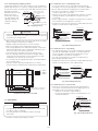
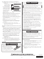
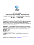
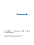
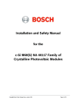
ETL LISTED
CONFORMS TO STANDARD UL 1703
CERTIFIED TO ULC ORD C1703
PHOTOVOLTAIC MODULE
INSTALLATION INSTRUCTIONS
1.INTRODUCTION
• BEFORE INSTALLATION, OPERATION, AND MAINTENANCE, BE SURE TO READ THESE INSTRUCTIONS AND USE THE PV
MODULE SAFELY.
• FOR INSTALLATIONS IN THE USA, REFER TO THE NATIONAL ELECTRIC CODE (NEC) AND ALL APPLICABLE LOCAL CODES.
FOR INSTALLATIONS IN CANADA, REFER TO THE CANADIAN ELECTRIC CODE (CEC) AND ALL APPLICABLE LOCAL CODES.
• FAILURE TO OBSERVE THE FOLLOWING INSTRUCTIONS MAY RESULT IN DEATH OR PERSONAL INJURY AND PROPERTY DAMAGE.
• KEEP THIS MANUAL FOR FUTURE INSPECTION.
WARNING
• DO NOT expose the PV module to artificially
concentrated sunlight.
• Cover the front surface of the PV modules with an
opaque cloth to prevent the generation of high voltage
and current during installation.
• Fasten the PV modules to the mounting framework
securely to prevent the modules from falling due to wind
or snow loads. The modules should be installed as
written in this installation manual.
• Securely ground the PV module frame and the mounting
framework where local regulations require this.
• Install a residual current device (RCD) as prescribed by
the local regulations.
• DO NOT expose backside of the module to the sunlight.
• Do not install the modules in places where they can be
shaded by objects such as buildings and trees.
1. GENERAL USE
• Avoid touching the front surface of the module with bare
hands.
• Do not handle except for installation and maintenance.
• Ensure that unauthorised personel, including children,
cannot get access to the modules.
2. GENERAL HANDLING
• DO NOT alter or remove any component.
• DO NOT stand or step on a module.
• DO NOT damage the front or rear surface of the PV
module. The rear surface may be damaged by sharp
objects.
• DO NOT throw or drop the PV module.
• DO NOT lift the module by the connectors or cables.
3. INSTALLATION
• Only licensed professionals should handle the modules.
• Secure yourself to avoid falling from the installation area.
• DO NOT use damaged the PV modules.
A damaged PV module may cause a fire and/or an
electrical shock with personal injury or even death.
ELECTRICAL SPECIFICATIONS
MODEL
Pmax
Voc
Isc
Vmp
Imp
*1 [A]
*2 [A]
PV-MLE255HD
PV-MLE260HD
PV-MLE265HD
PV-MLE270HD
PV-MLE275HD
TOLERANCE
255 W
260 W
265 W
270 W
275 W
*3
37.8 V
38.0 V
38.2 V
38.4 V
38.6 V
-
8.89 A
8.98 A
9.08 A
9.18 A
9.28 A
-
31.2 V
31.4 V
31.7 V
31.9 V
32.2 V
-
8.18 A
8.29 A
8.38 A
8.48 A
8.58 A
-
15
15
15
15
15
-
12.5
12.5
12.5
12.5
12.5
-
MAXIMUM SYSTEM VOLTAGE
600V (UL), 1000V (IEC)
(IEC61215, IEC61730, UL1703)
-
The electrical characteristics are within ±10% of the indicated values of Isc, Voc, and within +5/-0% of Pmax under
standard test conditions (irradiance of 1000 W/m2, AM1.5 spectrum, and a cell temperature of 25°C (77°F)).
Standard: IEC61215 ed. 2 (2005), IEC61730 ed. 1 (2004) Application Class A, UL1703
SYMBOLS DEFINITION
Pmax MAXIMUM POWER
Voc
Isc
Vmp
Imp
OPEN CIRCUIT VOLTAGE
SHORT CIRCUIT CURRENT
MAXIMUM POWER VOLTAGE
MAXIMUM POWER CURRENT
FUSE RATING BASED ON
MAX. BYMASS DODE AMPACITY WITHIN PV MODULE
*2 MINIMUM BYPASS DIODE RATING
*3 +5/-0% OF NOMINAL VALUE
*1
En-1
1-1. STRUCTURE
φ4.09[φ0.16](4 PLACES)
φ9[φ0.35](4 PLACES)
1625[64.0]
A−A(1:2)
B123456
W
W
V
V
A
A
A
A
9
φ4.0 6]
1
[φ0.
C(1:2,4 PLACES)
D
1200[47.2]
φ4.09[φ0.16](4 PLACES)
φ9[φ0.35]
21.5[0.85]
30[1.18]
E(1:2,4 PLACES)
Drainage holes
E
46[1.81]
10[0.39]
1-2. MULTIPLYING FACTOR
10[0.39]
C
1000[39.4]
Grounding Mark
6[0.24]
B
1167[45.9]
46[1.81]
A A
D(1:2,4 PLACES)
B−B(1:2)
B
Grounding Mark
φ4
[φ0 .09
.16
]
(−)
1019[40.1]
(+)
24.5[0.96]
25.3[1.00]
V
6[0.24]
Under normal conditions, the PV module is likely to experience conditions that produce more current and/or voltage than reported
under Standard Test Conditions. Accordingly, the values of Isc and Voc marked on this module should be multiplied by a factor of
1.25 when determining component voltage ratings, conductor capacities (cross sectional area), fuse sizes, and size of controls
connected to the PV output. Customers in US should refer to Section 690-8 of the National Electrical Code for an additional
multiplying factor of 125 percent (80 percent derating), which may be applicable. Customers in other location should refer to the codes
relevant to the location of installation for further guidance. Voc should be increased by a factor based on the lowest ambient
temperature recorded for the location. To determine the corrected value for Maximum System Voltage follow the guidelines in article
690.7 of the NEC or applicable section in the CEC. The voltage temperature coefficient for the module in use, should be used when
determining Maximum System Voltage.
2.INSTALLATION
2-3. MOUNTING
Refer to Local Code (US: National Electrical Code) standards
(Germany: DIN standards), construction rules and safety
instructions for installation of the PV module.
The electrical installation in Canada shall be in accordance with
CSA. C22. 1, Safety Standard for Electrical Installations,
Canadian Electrical Code, Part1.
WARNING
• Use mounting framework that can withstand forces from wind
pressure and snowfall pressure specific to your local climate.
• Use mounting framework and brackets that can withstand the
environment where the PV modules are to be used. Select
proper corrosion resistant materials and coatings.
• Use appropriate safeguards and components to install the
modules.
• PV modules shall be mounted over a fire resistant roof
covering rated for the application and on any slope less than
5in/ft (127mm/305mm) to maintain a fire Class rating.
2-1. CLIMATE CONDITIONS
Install the PV module within the following conditions:
• Ambient temperature: -20°C to 40°C (-4 to 104°F)
• Operating temperature: -20°C to 83°C (-4 to 181°F)
• Allowable pressure: below 3600Pa
• Water resistance/damage: PV modules shall not be
immersed in water and shall not be continually exposed to
water from a sprinkler, fountain, etc.
• Corrosion warning: PV module shall not be installed in
corrosive area like,
-- Salty area: area where salty water such as ocean
spray comes in direct contact with the module, or
-- Sulfurous area: area near sulfurous volcano and
sulfurous spring.
Note
In case of installation in Asian countries, PV module also
shall not be installed in corrosive area where within 500m
from a body of salt water and/or area where salty wind hit
directly.
CAUTION
• Make sure there is enough space for air circulation behind
the PV modules to dissipate heat. Minimum 89mm (3.5
inches) standoff height must be provided.
• DO NOT open any additional holes in the modules.
• The module is Class C fire rated.
2-3-1. Mounting using bolt holes
Examples of mounting method:
• Use the 4 corner holes of the PV module to bolt with M8
(5/16”) stainless steel to the mounting framework by 4.5 to
6N·m (3.3 to 4.4 ft-lb).
• Use spring washers and flat
Bolt
washers to fasten the PV module.
(Stainless steel, 5/16(M8))
• Install the PV module securely
Flat Washer
such as fastening the
(Stainless steel, 5/16)
appropriate bolts with double
Mounting structure
nuts and locking washers.
(Alminium)
• Space more than 5 mm
Flat Washer
between 2 modules (to
(Stainless steel, 5/16)
Spring washer
prevent from buckling a frame
(Stainless steel, 5/16)
of module affected by thermal
2 Nuts
expansion).
(Stainless steel, 5/16(M8))
2-2. ORIENTATION
• Install the PV modules facing South (in North Hemisphere),
or to the North (in South Hemisphere).
• PV modules connected in series should be installed at the
same orientation and angle. Different orientation or angles
may cause loss of output power due to the different
amount of sunlight exposed to each of the modules.
• Do not allow the modules to be shaded at anytime.
Shade causes loss of electrical output, even though the
factory fitted bypass diode of the PV module will reduce
such loss to some extent.
Fig. 1 Mounting of module
En-2
2-4-1. Method #1 (use of self-tapping screw)
• Secure the stainless steel screw (M5 or No.10) with 32
threads per inch to the grounding hole by 2.3N·m (20lbf-in).
• Ensure that 2 threads are engaged in the module frame.
• As shown in the figure 3, copper wire should be
compressed by the screw head.
• Stainless steel washer with appropriate corrosion resistant
coating should be inserted between copper wire and
screwhead.
• Proper cupped washer should be inserted between copper
wire and frame to avoid galvanic corrosion.
• Copper wire must have the thickness of #14 AWG or thicker,
and be secured with the module frame.
2-3-2. Mounting using "Clipping method"
"Clipping method" is the way to fix modules on the steady base
profiles (rail structure etc.,) with the "clipping" materials to catch
the top of the frame, not to directly fix with bolts and nuts on the
backside of module.
5mm min.
Frame (longer side)
Mitsubishi Electric Corp
(in principle)
bolt
doesn't specify or
Module
warrant any materials,
Clipping material
e.g. base profile and
clipping materials etc.,
related to clipping
Framework (base profile)
method.
Fig. 2 Clipping method
Module frame
Module frame
Copper wire (14AWG or thicker)
Cupped washer
(Stainless steel)
CAUTION
• Note that the drainage hole at each corner of module would
not be blocked by the base profile if the profile were placed
in parallel to the longer frame.
Stainless steel washer
(#10)
Self-tapping screw
(Stainless steel, #10-32TPI)
• Base profile should be placed in perpendicular to the longer
frame of module in principle (see figure).
• Module shall be fixed at 4 places or more on frames.
• Refer to the figure for the required area to be fixed.
• Close the gap between the material and frame, and secure
without loosing by M6 (1/4”) or larger bolts (M8 (5/16”)) for
where the heavy snow load is expected.
• The hooked area should be more than 5mm at least.
• Use the clipping material with sufficient strength and the
shape that can withstand forces from wind pressure and
snowfall pressure specific to local climate.
• Secure bolts with the appropriate torque avoid deformation
of the module frame.
• Take pre-caution utilizing locking fasteners to avoid
movement of the module from its original anchored position.
Cupped washer
2-4-2. Method #2 (use of ground lug)
• The appropriate device such as UL Listed ILSCO ground
lug, Cat. No. GBL4-DBT should be secured by stainless
steel screw (M5 or No.10) with 32 threads per inch by
2.3N·m (20lbf-in) as shown in the figure 4.
• The star or toothed washer shall be inserted between
ground lug and module frame.
• Copper wire must have the thickness of #14 AWG or thicker,
and be secured with the screw of ground lug.
Toothed washer
(Stainless steel, #10)
Self-tapping screw
(Stainless steel, #10-32TPI)
Grounding lug
Grounding lug
(ex. ILSCO GBL4-DBT)
(ex. ILSCO GBL4-DBT)
Toothed washer
(Stainless steel, #10)
Copper wire
Self-tapping screw
(14AWG or thicker)
(Stainless steel, #10-32TPI)
up to 3600Pa
up to 3000Pa
up to 2400Pa
619 (24.4)
1019 (40.1)
Self-tapping screw
(Stainless steel, #10-32TPI)
Stainless steel washer(#10)
(Stainless steel)
Fig. 3 Grounding method #1
Copper wire
(14AWG or thicker)
1625 (64.0)
Copper wire
(14AWG or thicker)
Fig. 4 Grounding method #2
600 (23.6)
900 (35.4)
1200 (47.2)
1400 (55.1)
2-4-3. Method #3 (use of bolt and nut)
• Stainless steel bolt and nut of No.8 with 32 threads per
inchcan be used instead of No.10 self-tapping screw in
Method #2 under the following conditions.
- Torque to secure bolt: 1.8N·m (16lb-in)
- Lock or spring washer shall be inserted between nut
and toothed washer.
Mounting area (4 places)
Framework (base profile)
Required mounting area to be fixed
Copper wire
(14AWG or thicker)
Nut (Stainless steel, #8)
Spring washer
(Stainless steel, #8)
Toothed washer
(Stainless steel, #8)
Grounding lug
(ex. ILSCO GBL4-DBT)
Bolt
(Stainless steel, #8)
2-4. GROUNDING
WARNING
• The grounding method should satisfy the Local Code and
the NEC or CEC accordingly.
• Securely ground the PV modules and the mounting
framework.
Fig. 5 Grounding method #3
Examples of proper grounding technique:
En-3
2-4-4. Method #4 (use of bolt and nut for mounting hole)
• All hardware used in this method must be stainless steel.
- Examples of
Bolt (Stainless steel, 5/16 (M8))
Spring washer (Stainless steel, 5/16)
acceptable grades of
Ring washer
stainless steel are
(Stainless steel, 5/16)
18-8, 316, and 410
Toothed Washer
• 1 1/4” bolt and double
(Stainless steel, 5/16)
Mounting structure (Alminium)
nuts of No.5/16 diameter
(or M8) shall be used to
Toothed Washer
(Stainless steel, 5/16)
mount the PV module to
Ring washer
the mounting structure
(Stainless steel, 5/16)
through the mounting
2 Nuts (Stainless steel, 5/16(M8))
hole (which has a
Fig. 6 Grounding method #4
diameter of 9mm).
• Torque to secure bolt: 5N·m (3.7 ft-lb)
• External toothed stainless steel washers shall be inserted
between the module frame and ring washer, and also
between mounting structure and ring washer.
• Spring washer shall be used to avoid loosening of bolt
• All 4 mounting holes of each PV module must be secured to
the mounting structure
• 2 of the 4 locations must have external toothed washers
utilized
• All four locations shall have 2 nuts installed
• A grounding electrode system for the mounting structure
must be provided in accordance with the NEC or CEC
accordingly.
• Recommended mounting structure characteristics;
- Alloys with resistivity less than 1.61 micro-ohms / inch
- Wall Thickness of at least 1/8”
CAUTION
• Connect required number of PV modules to meet the voltage
specification of equipment used in system.
Recommendation (see the enclosed specification sheet, too)
- Max. series: 12pcs due to max. system voltage
- Max. parallel: 2 strings due to fuse rating
• Connect the output cable connectors so that they do not
exert any force on the base of the cable at the junction box.
Attach the cable to the mounting framework using approved
fasteners.
The connectors should be placed behind the mounting
framework so that the connectors are not directly exposed to
sunlight, wind and rain.
• Do not apply external force (stepping, etc) to the connector.
• The PV module has a pair of male and female waterproof
connectors. For a series electrical connection, connect the
positive (+) connector of the first PV module to the negative (-)
connector of the following module.
• These modules employ UL Recognized connectors for the
output wiring. Final output field wiring should be done with
CCT9901-2352F (P51-6) (male), CCT9901-2452F (R51-6)
(female) from SMK and minimum 14 AWG copper wire cables
rated for 90°C (194°F).
These products will allow final system output wiring in
accordance with the U.S. National Electrical Code, NFPA
70-2008 or CEC accordingly.
Please refer to Article 690 of the NEC for additional guidance.
• To extend the cable, use proper commercial cables and
connectors that can withstand outdoor use for long periods.
Select the appropriate cable size according to its length to
avoid voltage drop.
Follow the cable manufactuer's instructions.
2-4-5. Method #5 (WEEB clips/ barbed washers and associated
racking)
• Barbed washers listed to UL467 intended for use in bonding
photovoltaic modules to mounting structures may be used
for grounding as described in NEC or CEC accordingly.
• When installing the WEEB UMC Clip or UniRac UGC-1 Clip,
as a means of grounding the modules, tighten the mounting
bolt to 13.5N·m (10lb-ft).
• Barbed washers identified for grounding must be installed in
accordance with the manufacturer's specified instructions.
• Recommended mounting structures that accommodate
barbed washers are manufactured by UNIRAC.
• Approved options of WEEB clips/ barbed washers to be
used in conjunction with UNIRAC racking solution are:
o WEEB UMC clip
o UNIRAC UGC-1 clip
Note: Barbed washers are intended for one time use only.
If a module is removed, replaced, repositioned or
remounted, the associated barbed washer(s) must be
replaced. Follow instructions of the manufacturer.
3.MAINTENANCE
WARNING
• Maintenance must be made only by qualified personnel.
• Be sure the circuit breaker is off, if it's applicable. Always use
appropriate safety equipment (insulated tools, insulating
gloves, etc.).
• Be sure to cover the front surface of the PV modules with an
opaque cloth to block sunlight when connecting or
disconnecting connectors of modules.
ANNUAL INSPECTION
• Check if nuts, bolts of mounting framework are secure and
not loose. Tighten all loose components.
• Check connections of cables, grounding cables and connectors.
• Check all electrical and mechanical connections for
freedom from corrosion.
• Check the ground resistance of metal parts such as the
module frames and the mounting framework.
Others
• Clean glass surface of module when glass surface is dirty.
(Wash or wipe only glass surface of module without using
detergent.)
2-5. WIRING
WARNING
• DO NOT short the positive and
negative cables.
• Make sure connectors are fully
engaged without a gap between
the insulators and shall be locked.
In case there is a gap, a fire and/or
an electrical shock may occur.
• Use the appropriate tool provided by SMK for disconnection.
All Rights Reserved. Copyright©2009: MITSUBISHI ELECTRIC CORPORATION
En-4
Printed in Japan
1210875HF4701
*875HF4701*