1
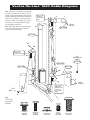
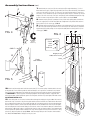
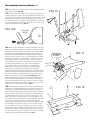
FITNESS
On-Line 1650
®
Owner’s Manual
Introduction
W
e at Vectra appreciate your selecting our On-Line® 1650 for your fitness
program, and invite your questions and comments. We're sure that you’ll be pleased with
your new Vectra gym.
This owner’s manual provides you with safety rules, assembly instructions and routine
inspection and maintenance information to enable you to get the most from your gym.
Please read through this manual carefully before you assemble and use your On-Line® 1650.
Routine Inspection
& Maintenance
The Vectra On-Line 1650 is designed to provide years of trouble-free service with
®
minimal routine maintenance. You can be confident of continued top quality performance
by carrying out the following periodic inspection.
PERFORM THE FOLLOWING SAFETY CHECK DAILY:
1. Inspect cables, cable ends and nylon jacket very carefully. Refer to Warning Label for
specific information on inspecting cables. This same information is repeated in this manual
and on your exercise chart. Replace any damaged or worn cables. Annual cable
replacement (semiannual in multi-user settings) is strongly recommended as an additional
precaution. The rate at which cables wear depends on many factors including: repetitions,
weight setting, misuse, abuse, etc. Because of this, periodic cable replacement is not a
sufficient safeguard against unexpected breakage. Nothing short of a thorough, careful daily
inspection constitutes an adequate safety program.
PERFORM THE FOLLOWING CHECKS WEEKLY:
1. Inspect frame and pulley bolts for tightness. Tighten if necessary.*
2. Inspect cable attachments (short and long single handles, double handles, lat or curl
bars, ankle strap, foot strap, triceps strap, sport handles such as racquet sports, golf, or
baseball, ab strap, squat attachments, etc.) carefully. Look for damaged mounting eyes,
springs, latches, etc. Inspect the webbing for fraying and check that the stitching is intact
and strong. Inspect all joints, fixed and pivoting. Make sure any bolts are tight and that
all retaining rings are intact and in good condition. Inspect any bearings. Replace any
damaged or worn items.
3. Inspect weight selector pin for proper fit and retention in selector shaft. Replace improperly
functioning pin (or other stack components) with Vectra replacement parts only.
4. Inspect press arm adjustment lever for proper function. Ensure that latch pin is engaging
each position fully. Replace improperly functioning parts with Vectra replacement parts only.
5. Inspect press arm mounting screws for tightness. Tighten if necessary.* Inspect all
springs, including press arm counter balance springs to make sure they are in good condition
and working properly. Replace any missing, damaged or worn springs with Vectra
replacement parts only.
6. Inspect bench bolts. Tighten if necessary.* Inspect bench wheels, wheel suspension
pivots, retaining rings, spring, and braking features for proper function. Replace any
damaged or malfunctioning parts.
7. Inspect leg developer mounting screws, pivots, bearings, and spring for tightness
and/or proper function. Replace any damaged or malfunctioning parts.
8. Inspect cushion bolts for tightness. Tighten if necessary.* Inspect cushion support
structure, squat attachments, pivots, guide wheels and associated latches. Remedy any
problems found using Vectra replacement parts only.
9. Inspect all molded parts such as pulleys, nylon bushings and cable stops. Make sure
all are intact, undamaged and secure. Replace any parts that are missing, worn or damaged.
10. Inspect cable retaining plugs and spring plungers. Replace if needed using Vectra
replacement parts only.
11. Inspect Cross Chest Fly or Butterfly arm pivots, retainers, attachment points and adjustment
mechanisms for proper function. Inspect pulley pivots, retainers, axles, bushings, attachment
points and rotation limiters for proper function. Inspect non-slip tread and rubber feet on
bench. Remedy any problems found using Vectra replacement parts only.
12. Adjust cable system tension if necessary (see assembly instructions for details).
13. Inspect stack column for proper rocking function. Inspect latch pins at base of stack column.
Inspect press arm for adjustment (center and fore-aft). Inspect stack column latch mechanism.
Repair, replace or adjust as necessary.
14. Inspect wheels on press arm. Repair or replace as necessary.
15. Inspect Leg/Calf Press option (if installed) for proper function and latching. Replace any
damaged or malfunctioning parts.
PERFORM THE FOLLOWING CHECKS MONTHLY:
1. Inspect all foam hand grips, pads, etc. Replace any damaged, worn, or loose parts.
2. Inspect weight plates for cracks, damaged bushings, etc. Replace if necessary. Check
bolt, tighten if necessary.
4. Clean upholstery with mild soap and water as desired.
5. If unit is in a humid area, such as near a pool, hot tub or sauna, or in certain climates,
use of an auto wax should delay rusting.
* If any bolts seem to loosen periodically, use Loctile 242 for a long-term cure.
Safety Rules
WARNING:
Serious injury can occur if you are struck by falling weights or moving parts. The risk that you
assume by using this type of equipment can be reduced by obeying a few simple rules:
1. IMPORTANT: Cables are a wear item. It is your responsibility to prevent unexpected
breakage. To do this, inspect every cable daily. Pay particular attention to areas near
fittings at each end of each cable. Access panels are provided, where necessary, for
this purpose. Replace worn, frayed, or damaged cables immediately. The actual wire
strands, the fittings, and the nylon jacket itself must all be scrutinized. Using or allowing
a machine to be used with a suspect cable can result in serious injury.
2. Inspect the nylon jacket of each cable carefully, again paying particular attention to
the cable ends. This nylon jacket is essential for cable life and safety. Any cable should
be replaced if the nylon jacket is missing, is damaged in any way, has pulled or shrunk
away from the fittings at the end of the cable, or is discolored. DISCOLORATION,
DARKENING OR BULGING OF THE JACKET IS AN EARLY INDICATION OF INTERNAL
PROBLEMS SUCH AS WEAR OR FRAYING.
3. Read and follow all instructions in your owner’s manual, on your exercise chart, and
on product warning/caution labels. Additional copies are available from Vectra Fitness,
Inc. or your dealer. Do not use this machine until you have taken the time to become
completely familiar with its safe operation.
4. Consult your physician before beginning your exercise program.
5. Do not allow young children to use or play with or around this machine. Allow older
children to use the machine only with adult supervision.
6. Keep body, hair, and clothing clear of weights and moving parts at all times. Keep
fingers clear of moving parts while making adjustments.
7. Inspect the gym for loose or worn parts, damaged, frayed, or worn cables, broken weight
plates, etc. Do not use or allow the machine to be used until any defective parts are repaired
or replaced. Refer to the “Routine Inspection and Maintenance” section of your manual for
specific inspection rules. Use only Vectra authorized replacement parts.
8. Ensure that the weight selector pin is in good working condition and fully engaged in
the selector shaft prior to lifting. Use only the Vectra supplied pin or a Vectra authorized
replacement.
9. Ensure that any locking mechanisms are properly engaged prior to lifting. Locking
mechanisms secure the following in position during use: seat pads, accessory items such
as squat attachments and lat hold downs, cable attachments, press arms, leg developers,
etc. An improperly engaged locking mechanism could result in an injury.
10. Obtain assistance to free jammed weight plates, pulleys, etc. Do not attempt to free
jammed weight plates by yourself. Falling weight plates can cause serious injury. Do not
pin the weight stack or top plate in an elevated position and do not use machine if found
in this condition.
11. Do not drop the weight plates. Lift only as much as you can control safely. Never use
dumbbells or other means to incrementally increase the weight resistance. Use only
those means provided by Vectra. Don’t be careless, stay alert.
12. Serious injury could result if equipment moves while in use. To prevent this, ensure
that the floor is even, strong, and not too slippery. If equipment slides too easily on floor,
place equipment on rubber matting. Errors in lifting form could also result in bench moving
in use. To prevent this, lift weight vertically only and do not push horizontally with your
feet while lifting.
13. Ensure machine is fully assembled in a Vectra Fitness authorized configuration per
owner’s manual prior to use.
Replace any warning or caution labels on product if damaged, illegible or removed.
CAUTION:
SELECT “FIXED MODE” BEFORE USING THIS WEIGHT MACHINE by pushing in the handle on
the tallest column. This press station offers an advanced free weight simulation that requires
the user to perform actual balancing work. “FREE MODE” should only be selected after
reviewing all information on exercise chart, labels and owner’s manual. (Certain exercises are
to be performed in fixed mode only.)
CAUTION:
ATTACH LEG PRESS CABLE TO CABLE ANCHOR when not connected to the low pulley cable.
Leg press footplate can move forward freely with no resistance if cable is not anchored. Before
using leg press, review exercise chart, all lablels, and owner’s manual.
Vectra On-Line® 1650 Cable Diagram
Note: The pulleys on this diagram are numbered
to make the installation of new cables as easy as
possible. Simply start threading the cables through
the pulleys beginning with the lowest number and
working up. For example, If you are installing an
entire set of cables, start at pulley #1. If you are
installing only a new ab/leg cable (PN 52750),
you would begin at pulley #20.
Note: Where applicable, text and other drawings
in this manual that mention or show pulleys
contain corresponding numbers.
Step 3, Cable
Adjustment.
See #21 (last
page).
2
1
4
HIGH
PULLEY
19
PN 52760
3
PN 52740
8
AB
20
Step 2, Cable
Adjustment.
See #21 (last page).
22
15”
EXTENSION
CABLE
9
PN 57820
PN 28840
PN 52750
11
PN 57790
21
10
17
7
6
18
5
16
12
14
23
LEG
15
13
LOW
PULLEY
Step 1, Cable
Adjustment.
Ball must touch
slot below it.
See #21 (last
page).
Note:
Leg/Calf Press
option cable is
PN 61000.
3/8-16 x 1/2
Hex Bolt
PN 55870
1/4-20 x 3/4
Hex Bolt
PN 20850
1/2
Shaft Retainer
PN 17750
Plastic
Hole Plug
PN 27990
1/2-13 x 1
Button Head
PN 13790
Assembly Instructions
Tools Required:
1. Select location for your machine. Set machine up in a well lighted and well ventilated
Wrenches: One each (7/16”, 1/2”), two each (9/16”)
Hex Keys: 5/16”
Phillips head screwdriver, hammer, pliers
2. Unbox entire unit, taking care to not bang parts together lifting them from their foam
area where you will enjoy exercising. Use rubber floor matting or carpet remnants to protect
your floor if desired.
supports. (NOTE: LEAVE ALL CABLE RETAINERS IN PLACE.) Lay large items, such as
the main column down until needed to prevent them from accidentally falling over. To make assembly as easy as possible, many cables are pre-routed at the
factory. Route and attach cables when the instructions call for it. After routing any cable, resecure it to prevent it from coming unrouted before going on. Some
bolts should be tightened very tight only after the instructions say to do so. All bolts should be tight at the end of assembly.
20
B
D
18
21
22
17
16
13
C
14
23
15
FIG. 1
E
3. Assemble the press arm support (A) to the main frame (B).
(3/8-16 x 1/2 hex screws, qty. 4). FIG. 1.
4. In preparation for threading the cable, position the main column (C) on the right of the main frame (B), and the leg/ab station (D) on the left. Lay these
parts down as shown in FIG. 1 to prevent them from falling over. You may tilt the main frame (B) on its left side to simplify cable routing. Now route the long
cable from the base of the main column (C) into the opening on the right of the main frame (B) around the nearest pulley #13 and up out of the frame. The cable
goes around the press arm pulley #14 such that the bolt head of the press arm pulley (E) is toward the bench, and then back down into the main frame (B) going
around the other of the two pulleys #15. The cable goes through the frame and exits out the opening near the leg/ab station (D). The cable enters the base of
the leg/ab station (D) through an opening in the bracket and goes under pulley #16 found there. There is a "cable-keeper" at this pulley. It is a small piece of
steel about the diameter of a pencil. It is VERY IMPORTANT that the cable go between the pulley and this "cable-keeper." Now the cable goes around the
lower pulley#17 of the suspended pair of pulleys, front to back. Refer to FIG. 1 and Cable Diagram elsewhere in this manual. Going around this pulley in
the correct direction without the cable twisted is VERY IMPORTANT. This cable next passes under pulley #18 and exits the column as shown.
5. In preparation for attaching the stack column (F) to the main frame (B), make sure that the rear of the main frame is 2 to 3 feet from the wall. The stack
column should have the guide rods (G) in place with the rubber bumpers (H) at the bottom and the screws up. IMPORTANT: The guide rods need to be in now
because ceiling height might make later insertion difficult or impossible. FIG. 2.
6. Stand the stack column (F) up forward of its final position. The rockers at its base go under the spring loaded positioning pins that protrude horizontally
above the felt. Place the rear of the rockers under these pins and work the column back carefully so as not to scratch the frame. Leave the factory installed
frame protectors in place throughout this step. FIG. 2. The positioning pins have
to rise and snap into the notches provided at the base of the stack column (F).
Because the springs holding down the pins are stiff, a fair amount of force is
F
GUIDE
required. For the last two inches, tilting the stack column (F) toward the press
RODS
INSIDE
arm support (A) helps by making the ramps less steep.
Pop one side in at a time. FIG. 3.
(If disassembly is someday
G
necessary, it is accomplished
by prying up on these
horizontal pins with a
very long screw driver
H
F
while pulling the
bottom of the stack
B
column (F) forward.)
Retain the frame
protectors for future
FRAME
disassembly/
PROTECTORS
reassembly.
IN PLACE
FIG. 2
FIG. 3
Spring loaded positioning pin shown in latched position
Assembly Instructions (cont.)
7. Now bolt the press arm lever (I) to the stack column (F) through the bearings. (1/2-13 x 1
button head screws, qty 2). Tighten very tight with 5/16" hex key. Allow the wheels on the bottom
of the press arm lever to rest in the "V" of the press arm support. Attach pulley (E) to the press
arm lever (I). The 5/16" diameter pin passes through the front of the press arm lever (I). On each
end goes one of the steel strips of the press arm pulley (E) with installed bushing and an e-ring
to retain it. Install e-rings with pliers. Make sure the cable is not twisted. FIG. 4.
8. Stand the main column (C) up and place it into position while pulling cable out under the
press arm support (A). Ensure that the cable feeds straight and is not pinched. Bolt column to
frame (3/8-16 x 1/2 hex screws, qty. 5). FIG. 5.
9. Feed the cable from pulley #18 in the bottom of the leg/ab station (D), into the opening in
the side of the stack column (F) and have it come out the top of the stack column (F). Stand the
leg/ab station (D) up and, making sure to not pinch the cable, bolt it to frame (3/8-16 x 1/2 hex
screws, qty. 5). FIG. 5.
F
Y
I
A
FIG. 4
FIG. 6
E
19
14
Neoprene
washer
E-RINGS
(Shown
actual size)
Nylon
spacer
Guide rod
CABLE
F
Weight pin ring
D
Rubber finish washer
5 bolts
each column
U-clip
C
FIG. 5
B
10. Now install the weight stack inside the stack column (F). First remove pulley 19 and the bolts in the tops
of the guide rods. Ensure that the guide rods and stack bumpers are in position as mentioned in step 5 above.
One at a time place weight plates onto guide rods at top of column with selector pin groove on bottom facing
out. IMPORTANT: To safely keep plates from banging together the following procedure is suggested: after
releasing each plate, pull the guide rods apart to slow the plates fall. Don't try to catch plates with hands or feet.
USE EXTREME CAUTION. FIG. 6.
11. After all 20 plates are in column, feed the cable end through the weight pin ring, the rubber finish washer,
and into the U-clip. Secure the U-clip to the top plate and the selector shaft with a 3/8-16x3 hex bolt. Now lower
this assembly down the guide rods. Reassemble the guide rods such that the bolts pass first through the bracket,
then the neoprene washers, then the nylon bushings and then into the threaded insert in the top of each guide
rod. Reinstall pulley #19 such that the cable goes around it as shown. Ensure that the cable passes between the
pulley and the “cable-keeper” above it. Look down the column to make sure that the cable is not wrapped around
itself or a guide rod. Tighten all bolts installed in this step. Lift the top plate to the top of the column. If it is sticky
near the top, adjust the guide rod spacing. FIG. 6. Label the weight stack per the instructions with the labels.
The “Press Arm Adds 25 lbs.” label goes on the press arm.
18
Assembly Instructions (cont.)
12. Bolt the leg seat handle/strut/leg developer pivot assembly (K) to the leg/ab seat
bottom (M) (1/4-20 x 3/4 hex screws, qty 4). Attach this assembly to the leg/ab station (D)
such that the hooks on the end of the strut go into the rectangular hole on the top of the
column (D). Line up the 1/2" holes and insert the pivot (1/2" diameter rod and shaft retainers).
Install shaft retainer with a hammer. Bolt the ab seat back/preacher curl cushion (N) to
the leg/ab station (D) (1/4-20 x 3/4 hex screws, qty. 4). FIG. 7.
13. Attach the leg developer (O) to the leg developer pivot assembly (K) (1/2-13x1
button head screw, qty. 2). Tighten very tight with 5/16" hex key. FIG. 7. Attach the cable
end to the leg developer (O), securing it with plastic hole-plug. FIG. 7A.
O
FIG. 7
N
M
K
FIG. 7A
O
D
23
FIG. 8
14. Attach the bench seat back (P) and bench seat bottom (Q) to the bench
(1/4-20 x 3/4 hex screw, qty. 10). The bench handle installs between cushion
(Q) and the bench frame and is held in place by 2 of these screws. Tighten
firmly. FIG. 8.
P
Q
handle
FRONT VIEW
FIG. 9
1" Washer
Cotter pin
1" Washer
Cotter pin
RIGHT
LEFT
15. Install right cross chest fly arm (arm closest to press station)
on pivot bar. The right arm is the one with the cam at the lowest point
on the arm. Install 1" washer and then cotter pin, bend end. Repeat this
process for the left arm. FIG. 9.
Assembly Instructions (cont.)
16. Connect cables to cross chest fly cams. Use plastic hole-plugs in keyholes
to prevent disconnection. FIG. 10A.
17. Install seat bottom (R) (1/4-20 x 3/4 hex screws, qty. 2). Note: If you are
installing a leg/calf press option, there are seat handles which install under
seat bottom (R). See instructions with the leg/calf press option for details. Install
the lat hold down (S) with the lever on the right pointing up. Line up the 1/2"
holes and insert the pivot (1/2" diameter rod and shaft retainers). Install shaft
retainer with a hammer. Install seat back (T) (1/4-20 x 3/4 hex screws, qty. 4).
Install one single handle per side (U). FIG. 10.
FIG. 10A
FIG. 10
T
U
S
LEFT CAM
DETAIL
R
18. Now install press handle (V). Insert the press handle (V) into the front
of the press arm lever (I) such that the pin engages one of the notches inside
with a bracket from the press handle on each side. A nylon bushing should
be positioned (slot toward weight stack) to engage each side of the press
arm lever (I). Secure each bushing with a bushing cap (W), bent flanges up.
Install the screws in the sides (1/4-20 x 1/2 pan head phillips, qty. 4) and the
tensioning screws (1/4-20 x 1-1/4 oval head, qty. 2). Tighten the 4 side screws
finger tight. Now tighten the tensioning screws until the slop is taken up.
Do not overtighten. Once the slop is removed from the pivot, but the joint
still rotates easily, tighten the 4 cross screws. Check the adjustment
lever's operation at this point. When the lever is operated in either
direction, the pin should retract fully, allow the press handle to rotate.
When the lever is released, the pin should lock the press handle by
snapping all the way into the next notch. Adjust if necessary. When correctly
adjusted, the latch pin will be forced by the spring all the way against the far
end of the slot it travels in. The adjustment lever will pull it almost, but not
all the way, to the other end of the slot. It is very important that it be
adjusted such that it goes all the way to the end of the slot with the pressure
of the spring. Now install the plastic cover (X). With the textured side out,
insert the narrow end down into the front of the press arm lever (I). Curve it
back and insert the end with the hole under the top of the press arm lever (I).
The hole snaps onto a hook inside to secure it. FIG. 11.
19. Next adjust the position of the stack column. First make sure all
frame bolts are very tight. Behind the stack, near the floor on each leg of the
main frame (B) you will find a bolt head. Turning either bolt head (9/16"
wrench) will move the bottom of that side of the stack column (F). Clockwise
moves the bottom of the stack back, counter-clockwise forward. Make sure
the "Mode Selection Knob" near the top of the main column (C) is in "Free
Mode." The wheels on the bottom of the press arm lever (I) will be in the "V"
of the saddle of the press arm support (A). First adjust the bottom of the stack
column to center the wheels on the press arm support (A). Once this is
accomplished, check the alignment of the "Mode Selection Knob." If it slides
into "Fixed Mode" easily, go to the next step. If it hits one side of the hole
first, more adjustment is necessary. To bring the top of the stack column (F)
toward the press station, the bottom of the stack needs to go away. Turn the
two bolt heads clockwise. Turn them an equal number of turns to keep the
press arm centered on the press arm support (A). To move the top of the stack
column back, turn the bolt heads counterclockwise. FIG. 12.
FIG. 11
TENSIONING
SCREWS
I
X
W
V
FIG. 12
F
B
Stack
Column
Position
Adjustment
Assembly Instructions (cont.)
FIG. 13
High pulley height
adjusting bolt
20. Adjust the high pulley member height now if necessary. Adjust
it up to provide additional pre-stretch for the tallest user, ceiling
height allowing. To do this, loosen the bolts that pass through pulley
#2 at the top of the main column (C). You will need two 9/16” end
wrenches for this as most other wrenches will not fit. Now tighten
(or loosen if adjusting down) the bolt on the top of the back of the
high pulley member. Once the chosen adjustment is reached, retighten
the bolts that pass through pulley #2. They must be very tight. FIG.13
T
Second
cable system
adjusting bolt
Loosen to adjust
high pulley, then
retighten.
FIG. 14
Adjust First
(Tighten bolt)
21. Next tension the cable system. Two adjustments are necessary, one for the ab/leg/press arm
stations and one for the fly/high pulley/low pulley stations. The adjustment at the top of the leg/ab
station is adjusted first, but first check something at the base of the main column (C). Remove the
lowest access door. There is a stainless cable fitting above a slot about six inches above the floor.
The cable system in the main column needs to have enough slack in it to allow this cable fitting to
touch the slot just above pulley #12. If the cable system does not allow the cable fitting to be pushed
into contact with the slot, then turn the bolt on the top of the main column counterclockwise until it
does. Now, remove the column cap from the top of the ab column. About 4" below the top of the
column, a bolt passes through pulley #22. Make sure it is not tight. Move the square bar from notch
to notch until the top plate of the weight stack just starts to lift. Make sure the weight selector pin
easily goes into all weight stack holes. Once the right notch is found, tighten up the bolt that passes
through adjustable pulley #22 to secure it. Now adjust the bolt on the top of the main column until
the top plate again just starts to lift. Again make sure the pin goes in all weight stack holes. Replace
column access panel and column cap. FIG. 13 and 14 and Cable Diagram.
22. Attach lat bar to cable at high pulley. Attach the ab strap at the ab pulley. Ensure that the
foam press post cap (Y) is in place on the press arm support (A). FIG. 4.
23. Make sure cables move freely when machine is operated. Immediately fix any cable rubbing
problems.
If you have any questions,
PLEASE contact the full-service
dealer where you purchased
this machine.
Vectra On-Line® 1650 Limited Warranty
Vectra Fitness, Inc. warrants, to the original owner only, this Vectra On-Line 1650 to be free from defects in materials and workmanship for component specific
periods as outlined below. Purchaser must retain bill of sale to establish warranty rights. This Limited Warranty applies to sales occurring on or after November 1, 2006.
Machines purchased prior to November 1, 2006 are covered under a different warranty in effect at the time of sale.This Limited Warranty is valid only if machine is
purchased from a Vectra authorized dealer. Defective parts will be repaired or replaced at Vectra’s option, when returned to Vectra Fitness, Inc., shipping prepaid with
prior authorization. No allowances for labor will be made.
Warranty Period: (All periods are from date of purchase by original consumer)
Home Use:
Structural Frame . . . . . . Lifetime
Weight Stack . . . . . . . . . .5 years
Guide Rods . . . . . . . . . . . 5 years
Pulleys . . . . . . . . . . . . . . .5 years
Bearings . . . . . . . . . . . . . . . . . . . . . . 5 years
Cables and Cable Attachments . . . . 3 years
Upholstery . . . . . . . . . . . . . . . . . . . . 3 years
Other parts not listed . . . . . . . . . . . .3 years
Home Use is defined as use in a family’s home by the members of that family. Lifetime means while owned by the original owner.
Commercial / Institutional Use:
This warranty is void if this machine is used in any type of commercial or institutional setting.
Commercial/Institutional Use is defined as any use other than Home Use.
Conditions and Exceptions: Failures due to misuse, abuse, neglect, alteration, improper assembly, repairs other than by an authorized Vectra Service Center, normal
wear, damage or lack of maintenance are not covered. Use of a weight stack that is heavier than the heaviest stack that Vectra Fitness sells for use on the machine
voids this Limited Warranty. This Limited Warranty does not cover damages sustained during shipment. Title passes to buyer upon delivery to carrier. If product is
damaged in transit, file claim with carrier.
Repairs to the Structural Frame and Weight Stack will be made only if such repairs are necessary to make the machine functional as designed. Repairs for other reasons
will not be made. Cosmetics are not covered by this Limited Warranty. This is a powder coated steel product, and as such rust-resistant in most settings. Any rusting
and/or corrosion is completely outside the scope of this Limited Warranty. Owners who live in humid climates or intend to install this machine in a humid area such as
outside, near a pool, hot tub, or sauna should apply an automotive wax to delay rusting. The corrosive effects of sweat, cleaners, body lotions, sunlight, etc. are also
the responsibility of the owner.
It is our policy to repair or replace components rather than entire machines or assemblies. It is also our policy to repair rather than replace frame components. Repairs of
structural parts will be made using appropriate technology and may be visible. Repaired items will be refinished as needed, but the new finish may not match the old.
Replacement and Repair Expenses: Vectra Fitness will provide only replacement parts or repair to parts under this Limited Warranty, and will pay for standard ground
shipping of such parts to the consumer. The owner of the machine is responsible for all other costs. Such costs may include, but are not limited to: labor charges for
service, removal, repair, and re-installation of the Vectra product or any component part; shipping, delivery, handling, and administrative charges for returning parts to
Vectra; all necessary or incidental costs related to installation of the repaired or replacement part.
Claim Procedure: Please contact the Vectra authorized dealer from whom you purchased your machine should warranty service be required. Items returned to Vectra
without prior factory authorization or freight collect will not be accepted. Vectra assigned RMA number MUST be prominently shown on OUTSIDE of carton. Copies of
original bill of sale MUST accompany any merchandise returned for warranty service. Also, each returned item must be accompanied by the following information: RMA
number assigned by Vectra, product serial number, description of problem experienced, and instructions for return of repaired/replaced part. Parts should be shipped
to Vectra Fitness in their original carton or equivalent packaging. Vectra Fitness will not be responsible for any loss or damage incurred in shipping.
No other express or implied warranties have been made or will be made on behalf of Vectra Fitness with respect to any Vectra product or the operation, repair or
replacement of any Vectra product. Vectra Fitness shall not be responsible for injury; loss of use of the Vectra product; inconvenience; loss or damage to personal
property, whether direct or indirect; or for incidental or consequential damages. This Limited Warranty is LIMITED STRICTLY to the terms stated herein and no other
express warranties or remedies shall be binding on us. THIS LIMITED WARRANTY AND ALL WARRANTIES WHICH MAY BE IMPLIED UNDER STATE LAW, INCLUDING,
BUT NOT LIMITED TO, WARRANTIES OF MERCHANTABILITY AND WARRANTIES OF FITNESS FOR A PARTICULAR PURPOSE, EXPIRE WITH THE TRANSFER OF OWNERSHIP
FROM THE ORIGINAL OWNER. ANY IMPLIED WARRANTY OF MERCHANTABILITY OR FITNESS FOR ANY PARTICULAR PURPOSE SHALL BE LIMITED TO ONE YEAR FROM
DATE OF PURCHASE. REPAIR OF THE PRODUCT AS PROVIDED UNDER THIS LIMITED WARRANTY IS THE EXCLUSIVE REMEDY OF THE CONSUMER. IN NO EVENT
SHALL WE BE LIABLE FOR INCIDENTAL OR CONSEQUENTIAL DAMAGES FOR BREACH OF THIS LIMITED WARRANTY OR ANY OTHER WARRANTY EXPRESS OR IMPLIED.
Some states do not allow limitations on how long an implied warranty lasts, or do not allow the exclusion of incidental or consequential damages, so the above limitations
or exclusions may not apply to you.
Consumers Rights: This Limited Warranty gives you specific legal rights, and you may also have other rights which vary from state to state.
Vectra Fitness, Inc.
7901 South 190th Street
Kent, WA 98032 U.S.A.
www.vectrafitness.com
Protected by one or more of the following Patent Numbers: RE34,572; 4,900,018; 4,986,538; 5,336,148; 5,378,216; 5,395,295; 5,462,510; 5,605,523; 5,672,143; 5,779,601;
6,482,135; 6,508,748; 6,582,346; 6,994,660; 7,150,701; D320,246; D320,247; D320,248; D329,563; D454,168; D457,581; D460,508; D462,731; CN1,309,738; CN2,023,972;
J3,117,451
Other U.S. and foreign patents pending. Vectra, On-Line and Cornerstone are registered trademarks of Vectra Fitness, Inc. Series VX, ARC (Automatic Ratcheting Cam),
AL (Arm-Leg), Vector, and VFT are trademarks of Vectra Fitness, Inc.
PN 62280, Rev. 5/07
©2007 Vectra Fitness, Inc.