1
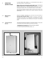
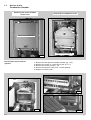
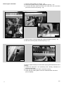
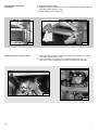
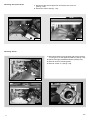
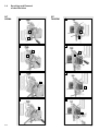
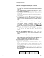
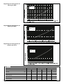
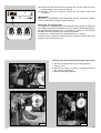
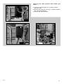
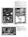
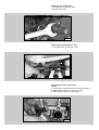
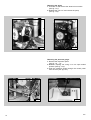
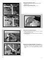
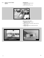
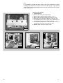
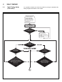
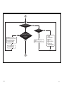
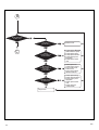
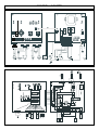
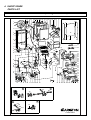
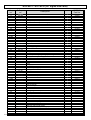
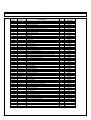
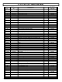
A/23 MFFI - A/27 MFFI
G.C.N. 47-116-10 / 47-116-12
Servicing Instructions
Type C Boilers
LEAVE THESE INSTRUCTIONS
ADJACENT TO THE GAS METER
TABLE OF CONTENTS
Page No.
1. SERVICING INSTRUCTIONS
1.1 Replacement of Parts
3
1.2 To Gain General Access
- Removing the Front Panel
- Removing the Side Panels
- To Lower the Control Panel
3
4
4
1.3 Access to the Combustion Chamber
- Removing the Sealed Combustion Chamber
- Removing the Burner and Injectors
- Removing the Electrodes
- Removing the Main Heat Exchanger
- Removing the Air Pressure Switch
- Removing the Venturi Device
- Removing the Fan
5
5
6
7
7
8
8
1.4 Servicing and Removal of the Gas Valve
- Setting Gas Pressure
- Removing the Spark Ignitor
- Removing the Gas Valve
9
11
12
1.5 Access to the Hydraulic Circuit
- Removing the D.H.W. (Secondary) Exchanger
- Removing the Safety Valve
- Removing the Automatic Air Vent
- Removing the Main Flow Circuit Switch
- Removing the Pump
- Removing the Pressure Gauge
- Removing the Expansion Vessel
- Removing the Overheat Thermostat
- Removing the Heating Temperature Sensor (N.T.C.)
12
13
13
13
14
14
15
15
15
1.6 Access to the Control System
- Checking the Fuses
- Removing the Time Clock
- Removing the P.C.B.s
16
16
17
2. FAULT FINDING
2.1 Fault Finding Guide (Flow-chart)
2.2 Fault Finding Using the Total Check System
18
23
3. ELECTRICAL DIAGRAMS
2
3.1 Electrical Connection
3.2 Functional Flow Connection
24
25
4. SHORT SPARE PARTS LIST
26
B029
1.
SERVICING
INSTRUCTIONS
To ensure efficient safe operation, it is recommended that the boiler is
serviced annually by a competent person.
Before starting any servicing work, ensure both the gas and electrical
supplies to the boiler are isolated and the boiler is cool.
Before and after servicing, a combustion analysis should be made via the flue
sampling point (please refer to the Installation Manual for further details).
After servicing, preliminary electrical system checks must be carried out to
ensure electrical safety (i.e. polarity, earth continuity, resistance to earth and
short circuit).
1.1
Replacement
of Parts
The life of individual components vary and they will need servicing or
replacing as and when faults develop.
The fault finding sequence chart in chapter 2 will help to locate which
component is the cause of any malfunction, and instructions for removal,
inspection and replacement of the individual parts are given in the following
pages.
1.2
To Gain General
Access
All testing and maintenance operations on the boiler require the control panel
to be lowered. This will also require the removal of the casing.
To dismantle the front part of the casing, proceed as follows:
1. Remove screw “A” (see fig. 1.1);
2. Lift the front panel up and forward (see fig. 1.2).
A
Fig. 1.1
B029
Fig. 1.2
3
Removing the side panels
1. Remove the screws “B”;
2. Pull the panel away from the boiler, then lift the panel
up and away from the boiler (see fig. 1.2).
B
To lower control panel
1. Remove the screws “B”
2. Push the two side panels outward slightly (fig. 1.5);
3. Rotate the control panel forward and down.
Fig. 1.3
B
B
Fig. 1.4
Fig. 1.5
To access the areas where the adjustment and control devices are located,
simply remove the plugs by pressing from the inside, unscrew the screws “C”
and remove the bottom part of the instrument panel, rotating it upwards.
C
Fig. 1.6
4
C
Fig. 1.7
B029
1.3
Access to the
Combustion Chamber
Removing the sealed chamber
frontal cover
D
Removing the combustion cover
D
E
E
E
Remove the screws “D”
E
D
D
E
E
E
Remove the screws “E”
Fig. 1.8
Removing the burner and the
injectors
Fig. 1.9
1. Remove the side panels of sealed chamber (fig. 1.10);
2. Remove the screws “F” of the burner (see fig. 1.11);
3. Remove the burner (see fig. 1.12);
4. Remove the injectors using a No. 7 socket spanner;
5. Replace in reverse order.
push
F
Fig. 1.11
push
Fig. 1.10
Fig. 1.12
B029
5
Removing the electrodes
1. Remove rubber gasket “G” (see fig. 1.13);
2. Disconnect ignition leads by pulling downward (see fig. 1.14);
3. To remove the flame sensor, disconnect the cable at its only connection
point close to the P.C.B. (see fig. 1.15);
Fig. 1.14
G
Fig. 1.15
Fig. 1.13
5. Remove screw “H” using a Philips No. 2 star tip screwdriver (see fig. 1.16);
6. Slide the electrode gently downward (see fig. 1.17).
H
Fig. 1.16
Fig. 1.17
To replace, repeat the steps in reverse order, paying particular attention to the
following:
a - Centre the electrode in the positioning hole carefully, otherwise the
electrode may break;
b -Check that the cables have been connected correctly;
c - Check that the rubber gasket covers the cable/electrode connection
point completely.
6
B029
Removing the main heat
exchanger
1. Drain the boiler of water;
2. Release the two connection nuts “I” connecting the exchanger to the flow
and return pipes (see fig. 1.18);
3. Pull it straight out (see fig. 1.19).
I
Fig. 1.19
Fig. 1.18
Removing the air pressure switch
1. Disconnect the electrical connections “K” and silicone pipes “L” from their
connection points (see fig. 1.20);
2. Remove screws “J” on the top of the sealed chamber (see fig. 1.21);
Use a No. 2 star tip screwdriver to remove the switch from the plate.
J
L
J
K
L
Fig. 1.20
Fig. 1.21
B029
7
1. Disconnect the silicone pipes “M” and remove the screw “N”
(see fig. 1.22);
2. Extract the venturi (see fig. 1.23).
Removing the venturi device
N
M
Fig. 1.22
Fig. 1.23
Removing the fan
1. Disconnect electrical connections and remove screws
“O” using a No. 2 star tipped screwdriver (see fig.1.24);
2. Pull fan to the right, forward and remove (see fig.1.25);
3. Remove fan from mounting plate;
4. Remove screws “P” (see fig.1.26).
O
O
Fig. 1.24
P
P
Fig. 1.25
8
Fig. 1.26
B029
1.4
Servicing and Removal
of the Gas Valve
SIT
SIGMA
SIT
TANDEM
1
1
B
B
A
A
2
2
D
D
C
C
3
3
E
E
4
4
F
F
B029
9
Setting gas pressures
Setting the minimum and the maximum power of the boiler
1. Check that the supply pressure to the gas valve is a minimum of 20 mbar
for natural gas.
2. To do this, remove the screw “A”.
Fit the pipe of the pressure gauge to the pressure connection of the gas
valve “B”.
When you have completed this operation, replace the screw “A” securely
into its housing to seal off the gas.
3. To check the pressure supplied by the gas valve to the burner, remove the
screw “C”. Fit the pipe of the pressure gauge to the pressure outlet of the
gas valve “D”.
Disconnect the compensation pipe either from the gas valve or from the
sealed chamber.
4. Set the On/Off button to position < I > and the "summer/winter" switch to
the winter position.
To set the maximum power, turn on the hot water tap and allow the hot
water tap to run at a rate of about 8 litres/minute so that the main burner
lights.
Adjust nut “E” on the modureg to set the gas pressure (displayed on the
pressure gauge) corresponding to the maximum power (see table “A” page 11).
5. To set the minimum power, disconnect a supply terminal from the modureg
and adjust screw “F”.
Turn the screw clockwise to increase the pressure and counter-clockwise to decrease the pressure (displayed on the
pressure gauge) corresponding to the minimum power (see table “A” page
11).
6. When you have completed the above operations, turn off the
hot water tap, re-connect the supply terminal to the modureg
on the gas valve and replace the cap on the screw of the
modureg.
Setting the maximum heating circuit power
7. To set the maximum heating circuit power, place the
On/Off button to position < I > and the "summer/winter" switch to winter
position.
Turn the knob of the heating thermostat clockwise to maximum;
8. Remove the left hand inspection panel of the P.C.B. and fit a small
cross-head screwdriver in to the right hand potentiometer. Turn clockwise
to increase the pressure or counter-clockwise to reduce the pressure.
Adjust the setting to the required heating pressure value (displayed on the
pressure gauge), as indicated in the diagrams shown in page 11.
9. Turn off the boiler by placing the main switch to the "Off" position.
Setting pressure for soft ignition.
Disconnect the detection electrode connection from the P.C.B. (see fig.
1.13).
Start the boiler and during the ignition sequence adjust the centre
potentiometer until the gas pressure reads the required gas pressure as
per the table below.
Once the gas pressure is set turn off the boiler and reconnect the
connection to the P.C.B.
NB.: It may be necessary to reset the flame failure reset a number of times
during this operation.
Recommended pressure for
slow ignition
10
NATURAL GAS (G20)
BUTANE GAS (G30)
PROPANE GAS (G31)
5 mbar - 1.95 in w.g.
18 mbar - 7.0 in w.g.
19 mbar - 7.4 in w.g.
B029
Regulating the heating power for
natural gas (G20)
model 23
model 27
Regulating the heating power for
butane gas (G30)
model 23
model 27
Regulating the heating power for
propane gas (G31)
40
38
36
34
model 23
model 27
TABLE “A”
NATURAL GAS (G20)
GAS REQUIREMENTS
PROPANE GAS (G31)
Gas rate
max
3.0 m 3 /h
106.0 ft 3/h
0.88 m3/h
31.1 ft 3 /h
1.15 m 3/h
40.6 ft3/h
Gas rate
min
1.2 m 3 /h
42.3 ft 3/h
0.35 m3/h
12.3 ft 3 /h
0.46 m 3/h
16.2 ft3/h
20 mbar
7.8 in w .g.
28 mbar
10.9 in w.g.
37 mbar
14.4 in w .g.
Inlet pressure
Burner pressure
max
12.3 mbar
4.8 in w.g.
28 mbar
10.9 in w.g.
37 mbar
14.4 in w .g.
Burner pressure
min
2.0 mbar
0.8 in w.g.
5.1 mbar
2.0 in w.g.
7.0 mbar
2.7 in w.g.
Burner injectors
B029
BUTANE GAS (G30)
13 x 1.25
13 x 0.72
13 x 0.72
11
10. Remove the pipe from the pressure gauge and connect screw “C” to the
pressure outlet in order to seal off the gas.
11. Carefully check the pressure outlets for gas leaks (valve inlet
and outlet).
40 50 60 70 80
C
C
IMPORTANT!
Whenever you disassemble and reassemble the gas connections, always
check for leaks using a soap and water solution.
Anti-cycling
Device
Soft-light
Adjustment
Max. Heating
Adjustment
Setting the anti-cycling device
This appliance is equipped with a potentiometer which delays the ignition of
the heating control and is situated on the P.C.B. (see the electrical diagrams).
By adjusting the potentiometer, it is possible to change the time interval
between the burner shutting down and its next ignition.
It is preset at 1 minute and can be adjusted from 0 to 2 minutes.
Use this control in particular situations where continuous shutting down and
ignition of the main burner occurs.
Removing the spark generator (SIT Sigma gas valve)
1. Disconnect ignition leads “Q” by pulling upwards
(see fig. 1.27);
2. Remove the screws “R” (see fig. 1.28) with a Pozidrive
No. 2 star tip screwdriver;
3. Remove the spark generator.
Q
Fig. 1.27
R
Fig. 1.28
12
Fig. 1.29
B029
Removing the spark generator (SIT Tandem gas
valve)
1. Disconnect ignition leads “Q1” by pulling upwards
(see fig. 1.30);
2. Remove the screws “R1” (see fig. 1.31) with a Pozidrive
No. 2 star tip screwdriver;
3. Remove the spark generator.
Q1
Fig. 1.30
R1
R1
Fig. 1.31
B029
Fig. 1.32
13
Removing the gas valve
1. Disconnect all the cables from the solenoid and
modureg;
2. Remove the spark generator;
3. Release the top nut “S” using a 30 mm open ended
spanner (see fig. 1.31);
4. Remove the screws “T” from the bottom of the gas
valve pipe (see fig. 1.32).
Attention!! The gas valve is connected with the two pipes
(as shown) with an O-ring connection.
S
T
1.5
Fig. 1.33
Fig. 1.34
Fig. 1.35
Fig. 1.36
Access to the
Hydraulic Circuits
U
T
Important! Before any component is removed, the boiler
must be drained of all water.
Removing the D.H.W. (secondary)
exchanger
1. Remove the screw “U” (see fig. 1.37);
2. Push the exchanger towards the rear of the
boiler, lift upwards and remove out of the
front of the boiler;
3. Before replacing the exchanger ensure that
the O-rings are in good condition and
replace if necessary.
U
Fig. 1.37
14
B029
Removing the safety valve
1. Loosen nut “V” (see fig. 1.38);
2. Remove the valve.
V
Fig. 1.38
Removing the automatic air vent
1. Unscrew valve “W” (see fig. 1.39).
W
Fig. 1.39
Removing the main circuit flow
switch
1. Remove the cable of the main circuit flow switch “Y”;
2. Remove the screws “Y1” (see fig. 1.40);
3. Remove the main circuit flow switch.
Y
Y1
Y1
B029
Fig. 1.40
15
Removing the pump
1. Unscrew “Z” and remove the electrical connection
(see fig. 1.41);
2. Release the nuts “A1” and remove the pump
(see fig. 1.42).
A1
Z
A1
Fig. 1.41
Fig. 1.42
Removing the pressure gauge
1. Remove the inspection panel
(see fig. 1.6 - 1.7);
2. Release coupling “A2” using a 14 mm open ended
spanner (see fig. 1.43);
3. Push the pressure gauge through the control panel
from the rear (see fig. 1.44).
A2
Fig. 1.43
16
Fig. 1.44
B029
Removing the expansion vessel
1. Remove nut “A3” away from the expansion vessel
(see fig. 1.45);
2. Remove nut “A4” (see fig. 1.46);
3. Remove expansion vessel (see fig. 1.47).
A3
Fig. 1.45
A4
Fig. 1.46
Fig. 1.47
Removing the overheat thermostat
1. Remove the electrical connection from the overheat
thermostat (see fig. 1.48);
2. Then remove the thermostat from the pipe by releasing
its securing clip.
Fig. 1.48
Removing the heating temperature sensor (N.T.C.)
1. Remove the electrical connector by pulling off the
thermostat connections and unscrewing the sensor
probe with a 14 mm open ended spanner (see fig.
1.49).
Fig. 1.49
B029
17
1.6
Access to the Control
System
Checking fuse
1. Remove the inspection panel
(see fig. 1.6 - 1.7);
2. Remove fuse (see fig. 1.50).
Fig. 1.50
Removing the time clock
1. Remove the inspection panel
(see fig. 1.6 - 1.7);
2. Remove electrical connection of the clock “A5”
(see fig. 1.51);
3. Unclip the clock from the panel and remove
(see fig. 1.52).
A5
Fig. 1.51
18
Fig. 1.52
B029
N.B.
It is possible to by-pass the time clock in the event of failure by simply
unplugging the electrical connection from the P.C.B. (see fig. 1.48). This will
revert control of the central heating to the room stat connection on the reverse
of the control panel.
A6
Removing the P.C.B.s
1. Isolate electricity;
2. Remove the front cover of the boiler;
3. Remove the inspection panel (see fig. 1.6-1.7);
5. Remove the mounting screws “A6’ (see fig. 1.53);
6. Disconnect the connection cable”A7” (see fig. 1.54);
7. To remove the 24V P.C.B.: remove the electrical plug
connectors and screws “A8” (see fig. 1.55);
8. To remove the 240V P.C.B.: remove the electrical plug
connectors and screws “A9” (see fig. 1.56);
9. Replace either P.C.B. in reverse order.
A6
A6
A6
Fig. 1.53
A8
A7
A8
A9
A9
A7
Fig. 1.54
B029
Fig. 1.55
Fig. 1.56
19
2.
FAULT FINDING
Fault Finding Guide
(Flow-chart)
2.1
It is possible to detect and correct any defect by using the standard fault
finding diagrams described in this chapter.
Preliminary Checks
Make sure that:
1) There is sufficient
water in the system
2) The gas is turned on
3) The electricity to the
boiler is on
Press the
On / Off Button
HAS
THE LIGHT fOR
THE POWER SUPPLY
COME ON?
NO
1) Check the fuses
2) Check the power
supply cord, plug and
outlet
3) Check/replace the power
supply PCB
YES
SETTING
FOR THE OPERATING
MODE
SUMMER
WINTER
FUME DISCHARGE TEST
IS HOT
WATER BEING
DEMANDED?
NO
YES
YES
IS HOT
WATER BEING
DEMANDED?
NO
NO
FOR BOILERS
EQUIPPED WITH AN
ELECTRONIC ANT-FREEZE
SYSTEM: HAS THE SAFETY BEEN
TRIGGERED TO ACTIVATE
THE DEVICE?
(T sensor <5°C)
DO THE
PROGRAMMING
TIMER AND/OR EXTERNAL
THERMOSTAT NEED
TO BE ACTIVATED
YES
YES
NO
A
FOR BOILERS
EQUIPPED WITH AN
ELECTRONIC ANT-FREEZE
SYSTEM: HAS THE SAFETY BEEN
TRIGGERED TO ACTIVATE
THE DEVICE?
(T sensor <5°C)
20
B029
A
DOES THE
CIRCULATION PUMP
COME ON?
NO
YES
POWER TO
THE PUMP?
YES
1) Check for air in the
system
2) Check the pressure switch
for activating pump
3) Check/replace water
gauge and refill the
the system properly
DOES THE
INSUFFICIENT WATER
INDICATOR LIGHT COME
ON? (within
40 sec.)
NO
1) Turn the boiler off
and then back on
again (safety reset)
NO
YES
1) Check to see if pump is
stuck
2) Replace circulation pump
1) Check
wiring
2) Check/replace
wire to PCB
3) Replace
power supply
PCB
4) Replace control
PCB
5) Check microswitch when hot
water is requested.
B
B029
21
B
DOES THE FAN
COME ON?
YES
NO
BOILER
SHUTDOWN?
YES
1) Reset the boiler
YES
1) Check/replace differential
pressure switch for pump
2) Check/replace wiring
3) Check/replace PCB wire
4) Check/replace power
supply PCB
5) Check/replace control
PCB
YES
1) Check/replace air
pressure switch/wiring
2) Check whether reset
button is stuck
3) Check/replace flame
detection electrode
NO
C
PUMP
SAFETY DEVICE
ACTIVATED?
NO
INTERNAL
SAFETY DEVICE
FOR PCB
ACTIVATED?
NO
IS THERE POWER
TO THE FAN?
YES
NO
1) Check/replace wiring
2) Check/replace PCB wire
3) Check/replace power
supply PCB
4) Check/replace control
PCB
5) Check/replace air
pressure switch
1) Replace fan
22
B029
C
IS
THE AIR PRESSURE
SWITCH ACTIVATED?
NO
YES
ARE THE
FUMES DISCHARGED
CORRECTLY?
NO
1) Check flue discharge
2) Check venturi & small pipes
3) Check wire for air press.switch
4) Check/replace air press. switch
5) Check/replace PCB wire
6) Check/replace power PCB
7) Check/replace control PCB
1) Check/replace igniter plugs
2) Check wiring
3) Check starter
4) Check small wire
5) Check power supply PCB
6) Check control PCB
YES
DOES THE
BURNER LIGHT?
NO
1) Check supply of gas to gas
valve
2) Check power supply PCB
3) Check control PCB
4) Check functionality of the
valve
YES
1) Check whether flame
detection electrode is
hit by the flame
2) Check the electrode
3) Check the power PCB
4) Check the control PCB
YES
SAFETY
SHUTDOWN OF THE
BOILER ACTIVATED?
NO
D
NO
WAS THE
RESET SWITCH
PRESSED?
YES
Shutdown LED off
Restart of the fan
B029
23
D
IS
THERE STILL A
PROBLEM?
YES
NO
FUNCTIONS
NORMALLY
LIST OF MALFUNCTIONS
- Air in the secondary exchanger
- Hot water pressure switch is defective
- 3-way valve is defective
2 Delivery of hot water for domestic use:
the radiatores are heated in summer mode.
- 3-way valve is defective
3 Delivery of hot water for domestic use:
water temperature is not satisfactory.
-
4 Delivery of hot water for domestic use:
noisy operation.
- Primary exchanger is defective
- Low water pressure in heating system
- Check gas settings and regulation
5 Drop/increase in pressure in primary circuit.
-
Check heating sensors
Check gas settings and regulation
Check water flow rate
Check exchanger for domestic hot water
Check for leaks in heating circuit
Defective water supply inlet valve
Secondary exchanger is defective
Expansion vessal is empty
6 Repeated shutdowns.
- Detection electrodes are defective
- Check gas settings and regulation
- Check electrical circuit for flamedetection
7 Safety thermostat is triggered repeatedly.
- Faulty (contacts) ntc heating sensors- Defective (poorly calibrated) safety thermostat
- Presence of air in the primary water circuit
8 When the cold water tap is turned off, the
boiler comes on.
9 Temperature of radiators not satisfactory.
24
POSSIBLE CAUSES
1 Delivery of hot water for domestic use:
when the tap is turned on, the burner goes out.
- Drop in pressure in the water mains, resulting
in water hammering
- Check ntc heating sensor
- Check by-pass
- Check gas settings and regulation
B029
2.2
Fault Finding Using the
Total Check System
Malfunction
Signalling
Boiler Off
1
2
3
4
5
6
Auto diagnostic state
A
b
C
d
Faulty ventilation system
E
F
G
I
m
Faulty flame detection
Air pressure switch stuck in N.O. position
Faulty reset switch
Faulty main circuit flow switch
Spark ignition state
Boiler functioning normally
Lockout
Boiler thermostat satisfied
Room thermostat/clock no demand or
selector in summer setting
Faulty overheat thermostat
Faulty exhaust fumes sensor
Faulty heating sensor (N.T.C.)
Faulty D.H.W. sensor (N.T.C.)
Pump fed
Main flow switch closed
Air pressure switch N.O.
Flame detected
Water at required temperature
Room thermostat/clock no demand or
selector in summer setting
Auto diagnostics faulty
D.H.W. exchanger efficiency control
Heating circuit efficiency control
Heating temperature control
D.H.W. temperature control
B029
25
3. ELECTRICAL
DIAGRAMS
Legend:
AT
BT
B
C
D
E
F
G
H
I
J
K
M
N
O
P
Q
R
S
T
U
V
W
X
Y
Aa
=
=
=
=
=
=
=
=
=
=
=
=
=
=
=
=
=
=
=
=
=
=
=
=
=
=
High Voltage P.C.B.
Low Voltage P.C.B.
Flame Failure L.E.D.
Insufficient Water Pressure L.E.D.
Water Temperature Indicator L.E.D.s
Overheat Thermostat Warning L.E.D.
System Reset Button
Selector Knob for Operating Mode
Domestic Hot Water Temp. Adjustment
Central Heating Temp. Adjustment
Wire Connector for Room Thermostat
Connector for Total Check System
Anti-cycling Device Adjustment for Heating
Soft-light Adjustment
Max Heating Temperature Adjustment
Time Clock Connection
On/Off L.E.D.
On/Off Switch
Interface Wire for P.C.B.s
Relay Motorised Valve
Ignitor Relay
Gas Valve Relay
Fan Relay
Circulation Pump Relay
Selector TCS2
Adaptor (British Gas use only)
A01 =
A02 =
A03 =
A04 =
A05 =
A06 =
A07 =
A08 =
A09 =
A10 =
A11 =
A12 =
Air Pressure Switch
Fan
Gas Valve
Ignitor
Motorised Valve
Circulation Pump
Flame Detector
Earth Terminal
Flame Detection Circuit
Flame Indicator L.E.D.
Transformer
Filter
B01 =
B02 =
B03 =
B05 =
B06 =
B07 =
B08 =
Over Heat Thermostat
Room Thermostat
Gas Valve Modulator
Heating Sensor
Pressure Switch for Heating Circuit
Microswitch for Diverter Valve
Time Clock
Colours
Gry
Rd
Bl
Grn/Yll
Wh
Brn
Blk
Wh/Rd
26
= Grey
= Red
= Blue
= Yellow/Green
= White
= Brown
= Black
= White/Red
B029
A/23 MFFI - A/27 MFFI
EX C-MI/FFI
8
B029
27
4. SHORT SPARE
PARTS LIST
A/23 MFFI - A/27 MFFI (SIT Sigma Gas Valve)
2 72
71 64
70 69 66 67 68 67 66 65 64 63 62 61 60 59 58
57
4
1
4
2
75
75
73
3
74
4
126
4
5
75
4
125
76
4
63
79
6
301
77
4
302
301
123
78
122
80
7
4
124
56
7
81
8
121
82
9
10
117
120
119
11
118
112
83 104
84
105
106
88
85
12
86
87
89
97
85
53
52
51
50
49
48
47
46
111
108
45
109
110
100
99
45
44
43
45
90
91
54
52
101
96
90
98
86
13
14
11
15
100
102
87
115
114
113
49
107
103
11
55
116
82
42
41
95
23
92
94
93
39
92
41
29
40
39
38
34
17
16
18
19 20
21
22 23 24 25
26
102
27
28
29 30 31 32 33 34 35 36
37
16
361
362
364
363
321
17
22
371
372
373
311
374
375
28
A 23/27 MFFI
B029
A/23 MFFI - A/27 MFFI (SIT Sigma Gas Valve)
B029
Key
no.
G.C. part
no.
1
11
14
17
18
19
23
24
25
28
32
45
46
47
57AB
57CD
58
61
72AB
72CD
75
84
85
87
89AB
89CD
90
92
96
98AB
98CD
100
101
102
108
112
116
118
119
120A
120B
120C
120D
121AB
121CD
301
311
321
361
362
363
364
371
372
373
374
375
381
382
379816
164 225
164 338
164 229
378 814
E03 818
E02 071
379 079
164 230
164 282
379 981
164 261
379 979
379 980
E02 026
E02 078
164 311
ARISTON
Part No.
Description
Expansion vessel
Gasket 3/4"
Overheat thermostat
Main flow Switch
Temp probe (C.H.W.)
Microswitch for 3-way/main flow group
Gasket 1/2"
Manual vent cock
Safety valve 3 bar 1/2"
Pressure gauge
Time clock
P.C.B. EX C-MI/FFI
P.C.B. EI A-MFFI
P.C.B. cable
Fan
Fan
Fan inlet gasket
Venturi (exhaust manifold/header)
Air pressure switch
Air pressure switch
Fastening spring
Automatic air release valve
Gasket 1"
O-ring
Secondary exchanger (plate-type) exchanger 23kW
Secondary exchanger (plate-type) exchanger 27kW
O-ring (secondary exchanger)
20-18 O-ring
Gasket 3/8"
Pump
Pump
O-ring (13)
Gasket
Gas valve (SIT Sigma)
Spark generator
Detection electrode
Gasket 1/4"
Ignition electrode (R.H.)
Ignition electrode (L.H.)
Main burner
Main burner
Main burner
Main burner
Main exchanger
Main exchanger
Front panel runner kit
D.H.W. actuator kit
SIT Sigma gas valve operator coils
Heating by-pass kit
D.H.W. pressure switch kit
3-way spring kit
D.H.W. diaphram valve
Main flow switch diaphram
Main flow switch magnet
Main flow switch spring
Main flow switch top cap
Main flow switch reed system
Burner jet 1.25 full kit (Natural gas)
Burner jet 0.72 full kit (LPG)
1
1
1
1
1
1
1
1
1
1
1
1
1
1
1
1
1
1
1
1
1
1
1
1
1
1
1
1
1
1
1
1
1
1
1
1
1
573294
573520
997206
573224
569236
573340
573528
573727
573172
571649
997208
953730
952981
952610
572989
572990
573343
573314
571651
571652
570717
564254
569387
571449
571646
573295
573825
571807
573521
997150
997151
571965
574279
574232
574233
573441
569390
569560
569561
572271
572277
572343
572372
572749
572835
571993
571444
997029
571443
571442
571447
571446
571547
571772
571771
571770
573138
569281
569282
29
A/23 MFFI - A/27 MFFI (SIT Tandem Gas Valve)
30
Key
no.
G.C. part
no.
1
11
14
17
18
19
23
24
25
28
31
44
46
47
57AB
57CD
58
61
72AB
72CD
75
84
85
87
89AB
89CD
90
92
96
98AB
98CD
101
103
106
114
118
120
121
122A
122B
122C
122D
123AB
123CD
311
321
322
323
361
362
363
364
371
372
373
374
375
381
382
379816
164 225
164 338
164 229
378 814
E03 818
E02 071
379 079
164 230
164 282
379 976
379 981
164 261
379 979
379 980
E02 026
E02 078
378 978
378 815
164 303
164 311
ARISTON
Part No.
Description
Expansion vessel
Gasket 3/4"
Overheat thermostat
Main flow Switch
Temp probe (C.H.W.)
Microswitch for 3-way/main flow group
Gasket 1/2"
Manual vent cock
Safety valve 3 bar 1/2"
Pressure gauge
Time clock
P.C.B. EX C-MI/FFI
P.C.B. EI A-MFFI
P.C.B. cable
Fan
Fan
Fan inlet gasket
Venturi (exhaust manifold/header)
Air pressure switch
Air pressure switch
Fastening spring
Automatic air release valve
Gasket 1"
O-ring
Secondary exchanger (plate-type) exchanger 23kW
Secondary exchanger (plate-type) exchanger 27kW
O-ring (secondary exchanger)
O-ring (20-18)
Gasket 3/8"
Pump
Pump
Gas valve (SIT Tandem)
Spark generator
O-ring (13)
Detection electrode
Gasket 1/4"
Ignition electrode (R.H.)
Ignition electrode (L.H.)
Main burner
Main burner
Main burner
Main burner
Main exchanger
Main exchanger
D.H.W. actuator kit
SIT Tandem gas valve operator coils
SIT Tandem modureg coil
Gas modulator cartridge
Heating by-pass kit
D.H.W. pressure switch kit
3-way spring kit
D.H.W. diaphram valve
Main flow switch diaphram
Main flow switch magnet
Main flow switch spring
Main flow switch top cap
Main flow switch reed system
Burner jet 1.25 full kit (Natural gas)
Burner jet 0.72 full kit (LPG)
1
1
1
1
1
1
1
1
1
1
1
1
1
1
1
1
1
1
1
1
1
1
1
1
1
1
1
1
1
1
1
1
1
1
1
1
1
573294
573520
997206
573224
569236
573340
573528
573727
573172
571649
997207
953730
952981
952610
572989
572990
573343
573314
571651
571652
570717
564254
569387
571449
571646
573295
573825
571807
573521
997150
997151
570732
573023
571965
573441
569390
569560
569561
572271
572277
572343
572372
572749
572835
571444
570712
573740
573745
571443
571442
571447
571446
571547
571772
571771
571770
573138
569281
569282
B029
A 23/27 MFFI (SIT Tandem Gas Valve)
B029
Key
no.
G.C. part
no.
1
11
14
17
18
19
23
24
25
28
31
44
46
47
57AB
57CD
58
61
72AB
72CD
75
84
85
87
89AB
89CD
90
92
96
98AB
98CD
101
103
106
114
118
120
121
122A
122B
122C
122D
123AB
123CD
311
321
322
323
361
362
363
364
371
372
373
374
375
381
382
379816
164 225
164 338
164 229
378 814
E03 818
E02 071
379 079
164 230
164 282
379 976
379 981
164 261
379 979
379 980
E02 026
E02 078
378 978
378 815
164 303
164 311
ARISTON
Part No.
Description
Expansion vessel
Gasket 3/4"
Overheat thermostat
Main flow Switch
Temp probe (C.H.W.)
Microswitch for 3-way/main flow group
Gasket 1/2"
Manual vent cock
Safety valve 3 bar 1/2"
Pressure gauge
Time clock
P.C.B. EX C-MI/FFI
P.C.B. EI A-MFFI
P.C.B. cable
Fan
Fan
Fan inlet gasket
Venturi (exhaust manifold/header)
Air pressure switch
Air pressure switch
Fastening spring
Automatic air release valve
Gasket 1"
O-ring
Secondary exchanger (plate-type) exchanger 23kW
Secondary exchanger (plate-type) exchanger 27kW
O-ring (secondary exchanger)
O-ring (20-18)
Gasket 3/8"
Pump
Pump
Gas valve (SIT Tandem)
Spark generator
O-ring (13)
Detection electrode
Gasket 1/4"
Ignition electrode (R.H.)
Ignition electrode (L.H.)
Main burner
Main burner
Main burner
Main burner
Main exchanger
Main exchanger
D.H.W. actuator kit
SIT Tandem gas valve operator coils
SIT Tandem modureg coil
Gas modulator cartridge
Heating by-pass kit
D.H.W. pressure switch kit
3-way spring kit
D.H.W. diaphram valve
Main flow switch diaphram
Main flow switch magnet
Main flow switch spring
Main flow switch top cap
Main flow switch reed system
Burner jet 1.25 full kit (Natural gas)
Burner jet 0.72 full kit (LPG)
1
1
1
1
1
1
1
1
1
1
1
1
1
1
1
1
1
1
1
1
1
1
1
1
1
1
1
1
1
1
1
1
1
1
1
1
1
573294
573520
997206
573224
569236
573340
573528
573727
573172
571649
997207
953730
952981
952610
572989
572990
573343
573314
571651
571652
570717
564254
569387
571449
571646
573295
573825
571807
573521
997150
997151
570732
573023
571965
573441
569390
569560
569561
572271
572277
572343
572372
572749
572835
571444
570712
573740
573745
571443
571442
571447
571446
571547
571772
571771
571770
573138
569281
569282
31
Stampa BIEFFE Recanati
Merloni TermoSanitari SpA - Italy
Commercial subsidiary: MTS (GB) LIMITED
MTS Building
Hughenden Avenue,
High Wycombe
Bucks HP13 5FT
Telephone: (01494) 755600 Fax: (01494) 459775
Technical Service Hotline: (01494) 539579
23 99 84 1268 000 - B029
Manufacturer: