1
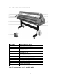
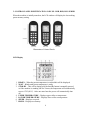
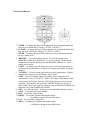
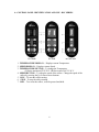
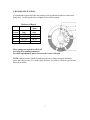
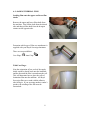
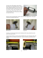
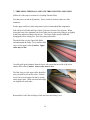
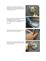
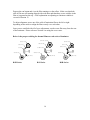
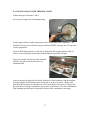
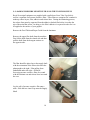
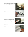
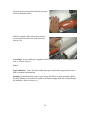
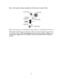
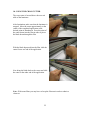
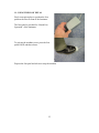
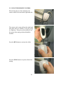
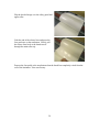
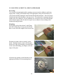
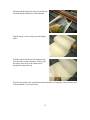
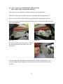
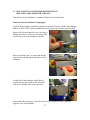
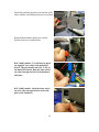
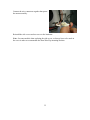
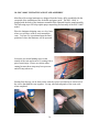
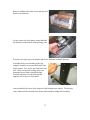
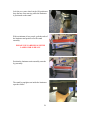
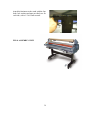
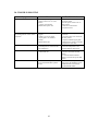
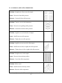
GUIDE TO ROYAL SOVEREIGN
LAMINATORS
ROYAL SOVEREIGN INTERNATIONAL, INC.
2 VOLVO DRIVE
ROCKLEIGH, NJ 07647
201-750-1020 / 800-397-1025
FAX: 201-750-1022
www.royalsovereign.com
TABLE OF CONTENTS
TOPIC
PAGE
1: SAFETY PRECAUTIONS
2
2: LAMINATOR KEY COMPONENTS
3
3: CONTROL PANEL IDENTIFICATION AND USE - RSH, RSR, RSS SERIES
4
4: CONTROL PANEL IDENTIFICATION AND USE - RSC SERIES
6
5: ROLLER NIP SETTINGS
7
6: LOADING THERMAL FILM
8
7: THREADING THERMAL FILM THROUGH THE LAMINATOR
14
8: ENCAPSULATION WITH THERMAL FILMS
17
9: LOADING PRESSURE SENSITIVE FILM ON THE TOP FILM SUPPLY
29
10: USING THE CROSS CUTTER
22
11: USING THE FOOT PEDAL
23
12: USING THE REMOTE CONTROL
24
13: ADJUSTING BRAKE PRESSURE
26
14: MOUNTING A DECALED IMAGE
28
15: MOUNTING A PRINT TO A PRECOATED BOARD
30
16: INSTALLATION OF THE FRONT FEED OPTION
(RSC-1400C, 1650C-H-HR, RSH -1650/1651)
32
17: INSTALLATION OF THE REAR REWIND OPTION
(RSC-1400C, 1650C-H-HR, RSH -1650/1651)
33
18: RSC-1400C UNCRATING AND STAND ASSEMBLY
36
19: MAINTENANCE
40
20: TROUBLE SHOOTING
41
21: COMMON LAMINATING PROBLEMS
42
22: GLOSSARY OF LAMINATING TERMS
43
©Royal Sovereign International, Inc. 2007 All Rights Reserved
1: SAFETY PRECAUTIONS
Failure to comply with any of the following safety procedures could result in serious
injury. Please read the instructions carefully and keep for future reference.
1. Only a licensed electrician should install wiring and outlet for the laminator.
2. Ensure the unit is plugged into a properly grounded outlet with the correct voltage.
3. Keep hands and clothing (e.g. neckties) away from rollers. The rollers have pinch
points that can trap body parts or clothing and cause serious injury.
4. Keep flammable and wet objects away from the machine.
5. Place machine on a level surface.
6. Avoid excessive sunlight, humidity and extreme temperatures
7. Ensure the unit is turned off, cooled, and unplugged from the outlet prior to
moving and/or repairing.
8. Keep out of the reach of children.
9. Only Royal Sovereign authorized maintenance and service technicians should
make repairs.
10. Do not attempt to laminate items that exceed the total recommended material
thickness for the unit.
11. When cleaning the machine, don’t use flammable sprays or materials
12. Do not touch the rollers when they are hot.
13. Do not place foreign objects inside the laminator.
14. Do not cover the surface of the machine until the machine has completely cooled.
2
2: LAMINATOR KEY COMPONENTS
NUMBER
1
2
3
4
5
6
7
8
9
10
11
12
13
PART DISCRIPTION
SAFETY COVER
EMERGENCY SWITCH
PAPER GUIDE
FEED TABLE
MAIN ROLLER
STAND ASSEMBLY
REMOTE CONTROL
FOOT PEDAL
TENSION CONTOL KNOBS
PRESSURE LEVER
CONTROL PANEL
UPPER IDLE BAR
RELEASE LINER TAKE UP
Note: Components may vary by machine model.
3
3: CONTROL PANEL IDENTIFICATION AND USE - RSH, RSR, RSS SERIES
When the machine is initially turned on, the LCD window will display the last working
preset memory setting.
Illustrations of Control Panels
LCD Display
1. READY – When the preset temperature is reached this will be displayed.
2. WAIT – Blinks until preset temperature is ready.
3. STND-BY – This will be displayed if the Stnd-By button is manually pressed
or if the machine is standing idle for 2 hours, the temperature will automatically
reset to 176F (80°C). After one more hour the power will automatically shut
off.
4. UPPER TEMPERATURE – Displays upper roller set temperature.
5. LOWER TEMPERATURE – Displays lower roller set temperature.
6. SPEED – Displays set speed.
7. PRGM – Displays set memory.
4
Control Panel Buttons
1. UPPER – To change the upper roller temperature by pressing the button and
then the up or down arrow. (Range: 32-320°F or 0-160°C)
2. LOWER – To change the lower roller temperature by pressing the button and
then the up or down arrow. (Range: 32-320°F or 0-160°C)
3. SPEED - To change the speed of the rollers by pressing the button and then
the up or down arrow.
4. MEMORY – To recall or change presets. To recall the settings, press
MEMORY and the up or down arrow. To save the settings, set the desired
temperatures and speed and then press the MEMORY button twice. Up to 9
presets can be stored.
5. C/HOT – To change the mode from hot to cold or cold to hot lamination. In
cold mode the speed defaults to 2 (Speed 1-4 settings) and standby function is
disabled.
6. T-CHECK – To check current upper and lower roller temperatures. Display
automatically returns to previous display after 5 blinks.
7. ST/BY – Press this button to change to standby mode (temperature will
automatically reset to 176°F-80°C). While is this mode, all the buttons on the
control panel are disabled. Press the ST/BY mode button to resume normal
operation. The laminator will go into STAND BY MODE if no activity is
made within 2 hours after each use. After one hour in STAND BY MODE, the
laminator will go into POWER OFF MODE.
8. REV– To reverse the rollers. You must press and hold the button to activate.
9. STOP – To stop the rollers from turning.
10. RUN – To start the rollers turning.
11. RESET – To reset the substrate and length counters.
(Available as option on some RSH Series)
12. FAN – To activate the cooling fans.
13. MEAS – To display the substrate and length counter
( Available as option on some RSH Series)
5
4: CONTROL PANEL IDENTIFICATION AND USE - RSC SERIES
RSC-1650HR
RSC-1650H
RSC-1650C/1400C
1. TEMPERATURE DISPLAY – Displays current Temperature.
2. SPEED DISPLAY – Displays current Speed.
3. TEMPERATURE BUTTON – To change the Temperature.
(H Series maximum122°F/50°C, HR Series max 266°F /130°C
4. SPEED BUTTON – To adjust the speed of the rollers. Change the speed of the
rollers by pressing the Up or Down arrow buttons.
5. RUN – To start the rollers turning.
6. STOP – To stop the rollers turning.
7. REV – To reverse the rollers, must be pressed and held.
6
5: ROLLER NIP SETTINGS
It is important to adjust the roller nip settings to the appropriate thickness of the board
being used. Use this guide below to adjust to the correct position.
Thickness of Board
No.
Inches
Metric
(mm)
1
Lamination Lamination
Closed
Only
Only
2
1/25”
1
3
3/16”-1/4”
5-7
4
3/8”-1/2”
10-13
5
3/5”
15
These settings are typical for all Royal
Sovereign free standing laminators.
For table top laminators please reference the Owner’s Manual.
NOTE: When you have finished laminating and are no longer using the laminator,
please place the pressure lever to the Open position (5) in order to eliminate any pressure
between the rollers.
7
6: LOADING THERMAL FILM
Loading films onto the upper and lower film
shafts:
Remove the upper and lower film shafts from
the machine. First lift the shaft from the slotted
side and then pull the shaft from the hexagon
retainer on the opposite side.
Determine which type of film core attachment is
supplied with your Royal Sovereign laminator.
There are two possibilities:
Core Plugs
Auto Grips
With Core Plugs:
Note the orientation of how each of the supply
shafts would be placed back onto the laminator
and the direction the film is wound onto the roll.
This will determine how to place the rolls of
lamination film onto the machine. All Royal
Sovereign films are wound with the adhesive
side facing in. If you are using another vendor’s
product, the winding of the film must be
ascertained.
8
Bottom film supply with Core Plugs:
Insert a core plug into the side of the roll with
the orientation of the film as shown in the
photograph to the right. (Film coming from the
bottom and pulling to the left.)
Insert the film shaft into the core plug and then
through the other side of the roll of lamination
film.
On the opposite side of lamination film, install
the second core plug onto the film shaft and into
the film core.
Install the film supply shaft back onto the
bottom of the machine while using caution
because the rolls of lamination film can be
heavy.
9
With using a tape measure, center the roll of film onto the laminator. Always measure
from the SIDE PLATE to the EDGE of the film, not the core plug.
Left Side
Right Side
Once centered, tighten both core plug screws
with a slotted screwdriver or coin.
Top film supply with Core Plugs:
Insert a core plug into the side of the roll with
the orientation of the film as shown in the
photograph to the left. (Film coming from the
bottom and pulling to the right.)
10
Insert the upper supply shaft into the core plug
then through the roll of lamination film.
On the opposite side, install the second core plug
onto the shaft and into the film core.
Install the film supply shaft back onto the top
film supply while using caution because the rolls
of lamination film can be heavy.
11
With using a tape measure, center the roll of film onto the laminator. Always measure
from the SIDE PLATE to the EDGE of the film, not from the core plug.
Left Side
Right Side
Tighten the core plug screws with a slotted
screwdriver or coin.
With Auto Grips:
Slide the four auto grip adapters onto the Supply
Shafts, two required for each shaft.
12
Locate the Auto Grip adapters on the shaft so
that when the roll of lamination film is centered
on the lamination machine, the Auto Grips will
be located just inside the ends of the core of the
roll of film. Lock the Auto Grip adapter down
onto the supply shaft with the Allen wrench
(2.5mm) provided. Note: There are two Allen
screws per Auto Grip.
Slide the rolls of lamination film onto the center of the film supply shafts. Note proper
orientation of lamination film below.
Bottom Feed
Top Feed
Load the two loaded supply shafts onto the laminator while using caution because the
rolls of film may be heavy.
Center the rolls of film by measuring from the EDGE of the roll of lamination film to the
SIDE PLATE of the laminator on each side. Do this for both the top and bottom film
supplies.
Left Side
Right Side
13
7: THREADING THERMAL LAMINATE THROUGH THE LAMINATOR.
Follow all of the steps in section five (Loading Thermal Film).
Turn the power switch on (I position). Power switch is located in the rear of the
laminator.
Set the upper and lower roller temperature to the recommended film temperature.
Take off the Feed Table and Paper Guide. Reference Section 2 for location. When
facing the front of the laminator, the Feed Table can be removed by lifting it up slightly
in the front and then pulling it toward you. The Paper Guide must be lifted and
disengaged before coming out. This varies between models.
Thread the film over the Upper Idle Roller
and underneath the Safety Cover until the film
rests over the upper roller (Caution: Upper
roller may be hot).
Carefully pull up the laminate from the lower roll around the back side of the lower
chrome idler roller (Caution: Lower roller may be hot).
The film lying over the upper roller should be
tacky from the heat from the roller. Tack the
lower film over the upper film that is resting
on the upper roller. Make sure that both edges
are aligned with each other.
Reinstall the Feed Table and Paper Guide and close the Safety Cover.
14
Adjust your nip setting to the thickness of the
leader board. (A board used to guide the laminate
through the entrance rollers and back through the
rear of the laminator exit.)
Place the leader board on the feed table and insert
by pushing the board until it reaches
the front nip point. The leader board should be as
wide as the film that you are feeding and 18-24
inches long.
Press the Run button while pushing the leader
board between the pair of main rollers.
Once the leader board has exited the back of the
machine, stop the laminator and set the nip to the
Laminating position.
15
Depress the run button and view the film running over the rollers. Make sure that both
rolls of film are still running aligned with each other and that there are no wrinkles in the
film as it approaches the nip. A full explanation on adjusting to eliminate wrinkles is
covered in Section 13.
To adjust alignment, move one of the rolls of lamination film to the left or right
depending on the need to realign the films exactly over each other.
Once you are satisfied with all of your adjustments, cut the waste film away from the rear
of the laminator. Please reference Section 9 on using the cross cutter.
Below is the proper webbing for thermal films on each series of laminator.
UPPER ROLL FILM
UPPER ROLL FILM
UPPER ROLL FILM
UPPER IDLE BAR
UPPER IDLE BAR
UPPER IDLE BAR
HOT METAL ROLLER
HOT METAL SHOE
HOT ROLLER
ROLLER
LOWER ROLL FILM
LOWER ROLL FILM
LOWER IDLE BAR
RSH Series
LOWER ROLL FILM
LOWER IDLE BAR
LOWER IDLE BAR
RSS Series
16
ROLLER
RSR Series
8: ENCAPSULATION WITH THERMAL FILMS
Follow the steps in Sections 5 and 6.
Set your nip setting to the Laminating setting.
Set the upper and lower roller temperature to the recommended film temperature. The
laminator will give you a WAIT message and then a READY message once it is up to the
correct temperature.
Press the RUN button and let several feet of lamination film run through the rollers in
order to even out the heat on the rollers and eliminate any possible hot spots.
Insert your images into the nip of the laminator
and let it run in between the two layers of
lamination film.
Once the image has exited the pull rollers in the back of the laminator, stop the machine
by depressing the STOP button on the front panel or on the rear remote. Remove the
print from the laminator by using the rear cross cutter (Refer to Section 9). Finally, trim
the print down on a paper cutter but be sure to leave a minimum of 1/8 inch of lamination
film extruding past the edges of the print in order to fully encapsulate your image.
17
9: LOADING PRESSURE SENSITIVE FILM ON THE TOP FILM SUPPLY
Royal Sovereign Laminators are supplied with a top Release Liner Take-Up which is
used as a separator for Pressure Sensitive films. These films are comprised of a sandwich
made up a three layers, film, adhesive and release liner. During the laminating process,
the release liner must be separated from the adhesive-backed film before it reaches the
nip of the main film rollers. In doing so, the film’s adhesive is exposed in order for it to
be applied to the surface of your graphic.
Remove the Feed Table and Paper Guide from the laminator.
Remove the upper film shaft from the machine.
First lift the shaft from the slotted side and then
pull the shaft from the hexagon retainer on
the opposite side.
The film should be placed on to the supply shaft
with the orientation of the film as shown in the
photograph to the right. Film pulling from
underneath and to the right. All Royal
Sovereign pressure sensitive films are wound
with the laminate out and release liner in toward
the core.
Lay the roll of pressure sensitive film onto a
table. Slide the two Auto Grips onto the Supply
Shaft.
18
Orient the two Auto Grips so that when the film
is centered on to the Supply Shaft, the Auto
Grips will just be slightly inside the film core.
Tighten both Auto Grips with the (2.5mm) Allen
Wrench.
Slide the Supply Shaft through the core of the
lamination film and center the film on to the
shaft. Note: Insert the hexagon end into the core
first (and not the end with the knurled wheel) as
seen in the photograph to the right.
Install the Supply Shaft back on to the top feed
of the laminator.
Thread the film under the top chrome idler roller
and down over the top roller.
19
Separate the release liner back from the pressure
sensitive lamination film.
Pull back enough of the release liner so that it
can be taped across the back of the film liner
take up core.
Core Plugs: If your laminator is supplied with Core Plugs instead of Auto Grips please
refer to Section 5 page 9.
Notes:
Top Lamination: You will need to load Kraft paper to the bottom supply shaft or use a
Sled to perform top lamination.
Decaling: (Lamination film on top of your image and adhesive on the underside) When
decaling, adhesive will need to be loaded to the bottom supply shaft and webbed through
the laminator. Refer to Section 14.
20
Below is the typical webbing configuration with Pressure Sensitive Films.
Note: Most typically you would run Kraft Paper, adhesive or a backing film on the lower
Film Supply depending on your application. Refer to the above diagram for proper lower
Film Supply webbing. With any product that has a Pressure Sensitive Adhesive, you
would need to bypass the Lower Idle Bar to prevent the adhesive from sticking to
the bar.
21
10: USING THE CROSS CUTTER
The cross cutter is located above the rear exit
table of the laminator.
After lamination, make sure that the laminator is
stopped. Move the cutter approximately to the
center of the completed application at the
desired point of detachment. Press the point of
the cutter down into the film in order to pierce
the blade down through the film.
With the blade depressed into the film, slide the
cutter first to one end of the application.
Now bring the blade back to the center and slide
the cutter to the other end of the application.
Note: With some films you may have to keep the film taut in order to obtain a
clean cut.
22
11: USING THE FOOT PETAL
Find a convenient place to position the foot
pedal on the floor in front of the laminator.
The foot pedal is provided for “Hands Free
Operation” of the laminator.
To activate the machine to run, press the foot
pedal ONCE and then release.
Depress the foot petal and release to stop the machine.
23
12: USING THE REMOTE CONTROL
When facing the rear of the laminator, the
remote control is located on the right hand side.
The remote can be removed from the right hand
side panel, where it is held by Velcro, by giving
it a slight tug. This gives you the ability to use
the remote from many positions behind the
machine.
Press the RUN button to activate the rollers.
Press the STOP button to stop the rollers from
turning.
24
Press and hold the REV button to reverse the
rollers. This is especially useful in case of a jam
or misfed media.
When you are finished laminating, replace the remote onto the Velcro pad.
25
13: ADJUSTING BRAKE PRESSURE
Brake is the process in which hold-back tension is applied to the roll of lamination film in
order to remove wrinkles in the laminate as it rolls over the main rollers. Start with little
or no resistance applied to the supply roll of lamination film.
The brake adjustment knobs are located on the
right side of the supply rolls when you are
facing the laminator.
To check the brake tension on the roll of film,
place your hand on the roll of laminate and see
how much resistance is apparent when you spin
the film back and forth on the supply shaft.
You should always start with a slight amount of
brake tension on the roll of film. Adjust the
brake tension by slowing increasing or
decreasing the pressure on the break spring.
Turning the knob clockwise increases the
tension and counterclockwise decreases the
tension on the roll of film.
Once you have this set, run some lamination film through the laminator and observe if
you have any wrinkles in the film as it passes over the main roller and into the nip. If you
see wrinkles, turn the break tension knob clockwise about half turn increments at a time.
It will take several feet of film to run through the laminator before you see the full effect
of your adjustment. Adjust the brake tension until the wrinkles disappear. Do this for
both the top and bottom rolls of lamination film.
26
Wrinkles in the lamination film
No wrinkles after brake adjustment.
Note: When encapsulating or putting film on both side of a graphic, it is important to
have equal amounts of brake tension on both rolls of film. If more tension is placed on
one of the rolls you may experience an upward or downward curl to your finished images.
Corrective measures:
If the image curls up:
Decrease the top roller tension or increase the bottom roller tension.
If the image curls down:
Increase the top roller tension or decrease the bottom roller tension.
27
14: MOUNTING A DECALED IMAGE
Decaling is the process in which the image has laminate on the top side and an adhesive
on the bottom forming a sticker.
Lay the decaled image face down on a flat
surface. Carefully peel back the release liner
(1 inch/25 mm) and put a crease along the edge
of the liner.
With the image face up, align the image squarely
onto the board. Tack the print down to the edge
of the board by pressing firmly in the center and
sliding your fingers out to the edge of the print.
Adjust the nip opening on the laminator to the
appropriate thickness of the mounting board.
Starting with the edge that you just tacked down,
insert the board into the nip of the laminator.
28
Flip the decaled image over the safety guard and
upper roller.
Grab the end of the release liner and press the
foot petal once or the run button. Slowly pull
the release liner back as the board travels
through the main roller nip.
Depress the foot pedal or the stop button when the board has completely exited from the
rear of the laminator. Trim as necessary.
29
15: MOUNTING A PRINT TO A PRECOATED BOARD
Precoating:
You can precoat mounting boards by running a pressure sensitive adhesive on the top
supply roller, setting your laminator nip to the appropriate setting for the thickness of
your boards and then running the mount boards through the laminator. Once the boards
exit the back end of the laminator, trim any excess. If your boards are narrower then the
width of the roll of adhesive you may find that you will need to run a roll of Kraft paper
on the bottom supply roller in order to keep the excess adhesive from sticking to the
laminator during operation.
Mounting:
Peel back the release liner about 1 inch/25mm
from the leading edge of your precoated board.
Run a crease down the length of the release liner.
Position your print so that is squarely on the
board. Starting from the center, tack the print
down to the edge of the board by pressing firmly
in the center and sliding your fingers out to the
edges of the print.
Adjust the nip opening on the laminator to the
appropriate thickness of the mounting board.
30
Starting with the edge that you just tacked down,
insert the board into the nip of the laminator.
Flip the image over the safety guard and upper
roller.
Hold the end of the release liner and press the
foot petal once or the run button. Slowly pull
the release liner back as the board travels
through the main roller nip.
Press the foot pedal or the stop button when the board has completely exited from the rear
of the laminator. Trim as necessary.
31
16: INSTALLATION OF THE FRONT FEED OPTION
(RSC-1400C, 1650C-H-HR, RSH -1650/1651)
This option is to be installed by an authorized Royal Sovereign Reseller.
The Front Feeder option includes 2 brackets, one spindle and mounting hardware.
Remove the Feed Table and Front Film Supply Shaft before attaching the brackets.
Below is the proper mounting orientation and placement of the brackets when facing the
front of the laminator.
Left Side
Right Side
Secure the brackets with four screws (1/4”/M6)
per side and fastened to the inside of the side
panel frame.
Once the supply shaft brackets are secured, place the spindle on the laminator. First
insert the spindle into the right side bracket and then secure the left side into the slot
provided.
32
17: INSTALLATION OF THE REAR REWIND OPTION
(RSC-1400C, 1650C-H-HR, RSH -1650/1651)
This option is to be installed by an authorized Royal Sovereign Reseller.
Make sure that the laminator is unplugged.
The Rear Rewind option includes the motorized rewinder, bracket, spindle, and mounting
hardware. RSC-1400C kit has an additional wire to connect the motor to the main PCB.
Remove the left and right side covers by using a
Phillips screwdriver. There are four screws that
attach each cover to the laminator side plate.
Remove the back panel. It is attached on both
ends, bottom and through the side plates of the
laminator.
On the back of the laminator, install the left
rewind motor to the outside of the side frame
with the six Phillips head screws provided.
Disassemble the main power switch bracket by removing the two screws from the
opposite side of the laminator.
33
Install the stationary bracket to the outside of the
frame with the six Phillips head screws provided.
Reattach the laminator main power switch
bracket to the rear rewind bracket.
RSC-1400C models: You will need to insert
the supplied wire cable to the main PCB
board. The slot should read CN6 T-UP on
the main PCB board. Run the other end of
the cable through the hole in the laminator
side plate.
RSC-1400C models: Push the other end of
the wire cable through the hole in the side
plate of the laminator.
34
Connect the wire connectors together that power
the motor assembly.
Reinstall the side covers and rear cover to the laminator.
Note: On some models when replacing the side covers, a slot may have to be made in
the cover in order to accommodate the Rear Wind Up mounting brackets.
35
18: RSC-1400C UNCRATING AND STAND ASSEMBLY
Most Royal Sovereign laminators are shipped from the factory fully assembled with the
exception of the installation of the feed table and paper guide. The RSC-1400C is
shipped with the body of the laminator assembled but separated from the stand assembly.
The following steps will help explain proper unpacking and assembly of the RSC-1400C
model.
Place the laminator shipping crate on a level area
where you will have room to work around the
crate. It is best if it is positioned near the final
position of where the laminator will be operated.
Locate the two metal banding strips on the
outside of the crate and remove by cutting with a
pair of metal snips. Please use caution when
cutting because these straps may have pressure
and will snap when cut.
Starting from the top, use an 8mm socket wrench or power screwdriver to remove all of
the screws that hold the crate together. Set top, side and end panels of the crate aside
when completed.
36
Remove cardboard box liner, foam end caps and
plastic over laminator.
Cut the center two white plastic straps that hold
the laminator to the bottom of the packing crate.
Locate the two legs, leg cross member and screws needed to assemble the base.
Assemble the leg cross member to the legs
using the four hex screws provided and a 6mm
Allen wrench. Two screws are needed for each
side. Make sure that the locking casters are
positioned across from each other during
assembly and not one to the front and the
opposite side to the rear of the stand.
Once assembled, take note of the location of the locking caster wheels. The locking
caster wheels will be oriented to the front of the laminator during final assembly.
37
Lock the two caster wheels in the ON position to
keep the base from moving while the laminator
is positioned on the stand.
With a minimum of two people, grab the ends of
the laminator and position over the stand
assembly.
PLEASE USE CARE BECAUSE THE
LAMINATOR IS HEAVY.
Position the laminator main assembly onto the
leg assembly.
The stand leg uprights seat inside the laminator
open box frame.
38
Attach the laminator to the stand with the four
bolts, lock washers and nuts provided, two for
each side, with a 1/2 in/13mm wrench.
FINAL ASSEMBLY VIEW
39
19: MAINTENANCE
Cleaning the body of the laminator.
To clean the machine body, dampen a cloth with water only and gently wipe the machine
clean.
Removing Adhesive Build Up.
Remove the film from the laminator.
Use a damp (water only) cloth and a rubber gum eraser to remove the adhesive on the
Teflon (metal) and Silicone rollers.
NOTE: Rub firmly but do not scrub the rollers vigorously as this may scratch the
surface. Do not use sharp metal objects, steel wool, or abrasives, as these may also
damage the rollers. Solvent cleaners should never be used because of electrical or heat
combustion.
40
20: TROUBLE SHOOTING
Symptom
Cause
Possible Solution
Machine will not turn on.
a. Power plug not plugged in.
b. Power switch in on “O” (off)
position.
c. Tripper circuit breaker
d. Blown main power fuse.
a. Plug the power cord into
appropriate outlet.
b. Put the power switch to the “I”
(On) position.
c. Reset the circuit breaker.
d. Replace the fuse.
There is power but the rollers are
not turning after the “RUN” button
is pressed.
a. Emergency switch(es) is (are) in
engaged.
b. Safety cover is not closed.
c. Paper guide is not installed
correctly.
d. Blown motor fuse.
The unit is not heating up.
a. The machine is in “COLD” mode.
b. Set temperature is lower than the
room temperature.
a. Upward curl.
b. Downward curl.
a. Disengage the emergency
switch(es).
b. Close the safety cover to activate
the safety switch.
c. Properly install the paper guide
so that the micro switch is activated.
d. Replace the motor fuse.
a. Switch to “HOT” mode.
b. Raise the temperature to the
recommended film temperature.
a. Loosen the top roll film tension
or increase the bottom roll film
tension.
b. Loosen the bottom roll film
tension or increase the top roll film
tension.
a. Raise the roller temperature
and/or lower the lamination speed
on RSH models or increase the
speed RSS/RSR models.
Curled Lamination.
Unclear Lamination.
a. The main roller temperatures are
too low and/or lamination speed is
too fast.
41
21: COMMON LAMINATING PROBLEMS
Problem: Straight wave lines across the output.
Cause: Excessive front roller pressure.
Measure: Loosen the front roller pressure
Problem: Concave waves in the lamination.
Cause: Excessive rear (pulling) roller pressure.
Measure: Loosen the rear back roller pressure.
Problem: Angled waves on both sides of output.
Cause: Insufficient rear roller pressure.
Measure: Tighten the rear roller pressure.
Problem: Angled waves on one side of the output.
Cause: Insufficient rear left (or right) side roller pressure.
Measure: Tighten the rear left (or right) side roller pressure.
Problem: Straight waves in the output.
Cause: Excessive heat at the nip rollers.
Measure: Lower the roller temperature.
Problem: Wake waves.
Cause: Insufficient heat at the nip rollers.
Measure: Raise the roller temperature.
Note: Any adjustments should be carried out by an authorized RS Service Technician.
42
22: GLOSSARY OF LAMINATING TERMS
Adhesion
The holding of two substrates by surface attachment.
Abrasion Resistance
The ability of a film to withstand rubbing without showing scuff marks.
Accelerated Aging
A means whereby the deterioration of a film encountered in natural aging may be
accelerated and reproduced in the laboratory.
Accelerated Weathering
A means whereby the deterioration caused by outdoor exposure may be accelerated and
reproduced in the laboratory.
Acrylic Resin
A glassy thermoplastic made by combining several acrylic acids used as coatings and
adhesives; used in Pressure Sensitive Adhesives.
Adhesion Build-Up
An increase in the peel adhesion value of a pressure sensitive film after it has been
allowed to dwell to the applied surface.
Adhesive
(Noun) A substance capable of holding materials together by surface attachment, in this
case acting as the mechanism which attaches film to a graphic arts media. (Adjective)
Type of bonding interaction between a thermal adhesive and the surface of a graphics
media or film to which it is laminated.
Brake
The amount of hold back tension that is placed onto the supply roll of film during the
lamination process.
Bond Strength
Refers to one of three conditions:
1. Anchor strength of adhesive to the substrate in laminating film
2. The anchor strength of the laminating film to the product that has been laminated
3. The strength of adhesive-to-adhesive bond when two layers of film are laminated
together.
Cast Vinyl
A premium vinyl lamination film used in the vehicle wrap industry because of its high
durability and conformability characteristics.
43
Cohesion
(Verb) The process or interaction that opposes separation within a layer of a multilayer
structure. (Noun) also known as COHESIVE STRENGTH. The ability of a material to
resist splitting or separating into layers within itself; or the minimum force required to
separate the material.
Cold Flow
The tendency of a pressure sensitive adhesive to act like a heavy viscous liquid over long
periods of time. Such phenomena as oozing and increases in adhesion are the result of
this characteristic.
Color Shift
Change in the apparent color of the ink/toner after laminating.
Color Stability
The ability of a film to retain its original color, particularly when exposed to light.
Conformability
The ability of film to fit snugly or make essentially complete contact with the surface of
an irregular surface without creasing or folding.
Contamination
Foreign substance in the film, i.e., bugs, wax, fiber, trim, drool.
Copolymer
The combination of two or more polymers used in the formulation of lamination
adhesives.
Core
The cardboard tube to which the laminate or adhesive is wound too. The size is referred
to the inside diameter of the tube.
Corona
or Corona Treat. Method of treating films to increase DYNE levels, promoting adhesion.
Curl
Tendency of laminated product to roll up or down at edges after cooling. Curl tends to be
magnified by excessive heat and/or tension.
Decaling
The process in which the image has laminate on the top side and an adhesive on the
bottom forming a sticker.
44
Delamination
Most commonly referred to as the separation of the lamination film from the substrate
that it was originally adhered to in the finishing process.
Dimensional Stability
The ability to retain its shape with temperature and or humidity shifts.
Dwell Time
Amount of time that the laminating film is exposed to the heat source in a laminator.
Dyne
Measure of surface energy (surface tension) of a surface. Important for adhesion and ink
receptivity.
Elastic Memory
A tendency of some BACKINGS or BASE FILMS to attempt to return to their original
length after being elongated.
Encapsulation
A finishing term when the end product is totally encased with the lamination film on the
top and bottom side and usually at least at 1/8 of an inch of lamination film bleeds past
the image on all sides. The image is totally sealed with lamination film on the top,
bottom and particularly the sides.
Film Gauge
Refers to the total thickness of a particular film construction including its individual
layers. The gauge is measured with a micrometer. The unit of measure is in thousandths
of and inch (mils) or microns.
Film Ratio
or Film-To-Adhesive Ratio or Thickness Ratio. Ratio of the thickness of the base film
to the thickness of the adhesive layer in a laminating film.
Flush Cut
The trimming of the excess lamination film from the edges of the laminated image.
Gap
The amount of distance between the top and bottom feed rollers of a lamination machine.
Glossy
The surface of the lamination film having a shinny or glass like appearance.
Lamination
A product made by bonding together two or more layers of material and the process of
bonding them.
45
Master Roll
The term used to describe the manufactured roll from which the narrower rolls of
material are cut or slit from.
Matte
A type of lamination film having a dull or none reflective surface. Used when the low
reflectivity from lighting is required of the image.
Micron
A measurement of thickness of material. 25 micron is equal to 1 Mil.
Mil
The term used for the thickness of lamination film. In measurement, 1 thousandth of an
inch.
Examples: 1 Mil = .001”, 3 Mil = .003”, 10 Mil = .010”
MSI
Abbreviation for thousand (M) square inches (SI). A commonly used unit of measure for
thermal laminating films
Nip
On a lamination machine, the contact point of the top and bottom lamination rollers.
PET
An extremely strong grade of polyester.
Polyester
Thermoplastic Polymer used as the base film of many laminates. Also known as
Polyethylene Terephthalate. It is produced from chemical substances found mainly in
petroleum.
Pressure Sensitive
Lamination film or adhesive that is applied to the image by the use of pressure and not
heat.
PVC
Short for Polyvinyl Chloride. One of several films used as the base of laminates or
adhesives. Commonly referred to as “vinyl”.
Ratio
A number that corresponds to the thickness of the film base vs. the adhesive.
Example: 5 mil laminate with a ratio of 3/2 would be 3 mil base film thickness and 2 mil
adhesive thickness.
46
Release Liner
A paper stock coated on the inside with a silicone layer used with pressure sensitive
laminates and adhesives.
Satin
A middle reflectance laminate surface between glossy and matte. Sometimes also
referred to Pearl of Luster.
Silvering
A term used when air is trapped between the laminate and the image during finishing,
giving it a metallic or silver look. Caused by insignificant pressure or tack of the
adhesive when using pressure sensitive films.
Sled
A board used to start the laminate through the lamination machine. Also used as a carrier
board when only face laminating an image.
Splice
How film ends are jointed together to make a straight continuous web.
Squeeze Out
When the adhesive of thermal or heat activated film is forced out of the edges of the
lamination film by excessive pressure or heat.
Textured
A type of lamination film having embossed surface pattern. Examples would be the look
of canvas, leather, artists brush strokes, or weave.
Thermal
Laminate of adhesive that is applied with heat to melt or activate the bonding agent.
Tunneling
A term used when the print separates from the mounting substrate causing tunnels to
appear across the image. The image raises off the mount board and creates linear tunnels.
UV
or Ultraviolet. Wavelength band of light, particularly prevalent in sunlight. UV can be
used to cure inks or adhesives. UV can also cause inks and media to degrade.
Web
The term used when routing the lamination film through the machine.
Wetting
With thermal film, when the adhesive goes from a dry to the touch state to a tacky or wet
state. Usually at the point where the film goes from cloudy to clear when heated.
47
©Royal Sovereign International, Inc. 2007 All Rights Reserved
Version 1.1 5/07