1
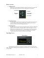
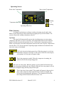
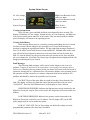
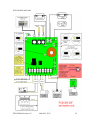
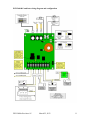
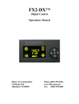
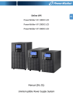
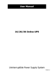
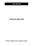
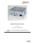
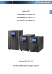
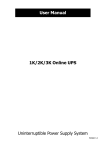
FX2-CHILLER™ Digital Control Operations Manual Micro Air Corporation 124 Route 526 Allentown NJ 08501 Phone (609) 259-2636 www.Microair.net Fax (609) 259-6601 Introduction: The FX2-CHILLER digital control operates onboard tempered water equipment to provide closed loop water temperature control. The FX2-CHILLER digital control is designed to operate with central type tempered water marine air-conditioning systems. Features include: High visibility Organic Light Emitting Diode display (OLED) offers superior visual characteristics compared to LCD displays. Variable brightness adjustment and automatic screen saver. Four position menu navigation switch featuring a joystick style interface with push on / push off control. The display is compatible with Vimar and Gewiss frames. Visual symbols enable the viewer to see the operating status at a glance. Easily programmed for customized operation. Built in options for fault protection help aid trouble diagnosis and prevent system damage. Universal 115/230 VAC 50/60 Hz power supply. FXII Chiller Revision: 05 March 25, 2013 2 Before you start: 1. Applying power: When power is first applied, the display will show the software revision, and then return to the last state the unit was in when power was removed. On/Off Button Up Button Mode Select Button Service Button (Unmarked) Down Button 2. Joystick operation: The four position joystick may be tapped up, down, right, left or in the center to make changes to the operation of the control. Gently tap this switch to operate it. Excessive force will damage the switch. 3. Operating states: Pressing the joystick in the center will toggle between OFF and ON. When the display is OFF the display will appear dark**. When the display is ON, the display shows the operating screen**. See operating screens for an example. Switch between these states by pressing and releasing the On/Off button. **Unless screen saver is active. See screen saver for details. Operating Screens Screen Saver If no buttons are pressed for two minutes, the display will enter the screen saver mode. The display will dim and icons will scroll across the screen. To exit this mode, just tap any button. FXII Chiller Revision: 05 March 25, 2013 3 Operating Screen Water Inlet Temperature Water Outlet Temperature Heating or Cooling Temperature Set Point Operating Status Icon Mode Selection To change from heating to cooling or cooling to heating, tap the mode select button. Set the desired loop water temperature by tapping the up or down button. The system will provide cooling or heating as selected. Operation The control will automatically operate the circulating pump, sea water pump, compressor and heater or valve as necessary. Inlet temperature must be more than two degrees from the set point for operation to occur. In heat mode, temperatures must be below set point and in cool mode temperatures must be above the set point. Temperatures must be above 33°F for any operation. Operating output conditions are indicated in the icon at the center of the display. CW is the closed circulating water loop. When the pump is on, the icon will animate and show water flow in the system. If the flow switch opens, or the pump is off, the pipe will appear empty. This is the compressor symbol. When the compressor is running, the symbol will look like an operating piston. SW is the sea water pump. When the pump is on, the symbol will animate and show the pump operating and water flowing. When the sea water pump is off, the pipe will appear empty and the pump will not spin. This is the electric heat symbol. This symbol will appear in heat mode in place of the compressor if the optional electric heater is installed and selected in the programmable parameters. The animation will look like heat rising from the element when the heater is on. FXII Chiller Revision: 05 March 25, 2013 4 System Status Screen AC Line voltage High Freon Pressure Switch (CLosed or OPen) Low Freon Pressure Switch (CLosed or OPen) System Current System Frequency Flow Switch (CLosed or OPen) Viewing System Status In the ON state, press and hold the Mode select button for three seconds. The display will indicate AC line voltage, System current, AC Line frequency, and High and Low pressure switch status and Flow switch status. After one minute without a button press, the display will return to the operating screen. Viewing Fault History Fault message history may be viewed by pressing and holding the service button for three seconds with the display in the operating screen. Scroll from message to message by tapping the up and down buttons. The past eight fault messages, numbered from 1 to 8 can be viewed with the most recent numbered 1. Multiple faults of the same type will not be listed separately unless they occur more than one hour from the first fault. To clear the history log, the screen must show the operate screen. Press and hold the service button for 10 seconds. The history log will appear then the displayed fault will disappear indicating the log is cleared. Fault Messages The following fault messages will be shown on the display in the event of a problem. Compressor and electric heat operation is prevented for two minutes after a fault occurs. Following this two minute period, the control will restart in the last mode of operation. Pressing the on / off button twice will return the display to the operating screen but operation will not resume for two minutes. Repeated faults are an indication of a problem and should be checked by a qualified service person. LOCKOUT Four of the same faults occurred in less than 1 hour from the first fault. The display will show the fault that caused the lockout followed by the word “LOCKOUT”. Press the On/Off button twice on the display to clear a lockout. HIGH FREON PRESSURE: Indicates the high pressure switch connected to the High/Low Freon jack is open. If the switch resets, the compressor will restart within two minutes. LOW FREON PRESSURE: Indicates low pressure switch connected to the High/Low Freon jack is open for over 10 minutes. The LP jumper (JP7) on the FX2 power supply must be cut to enable this option. LOW AC VOLTAGE: The AC line voltage was below the voltage set in the programmable parameters for more than 10 minutes. FXII Chiller Revision: 05 March 25, 2013 5 OVER CURRENT: The total system run current exceeded the limit set in the programmable parameters. Systems may start with currents exceeding the limit but must be below the limit within two seconds after the start of the compressor. FREEZE FAULT: The closed circulating loop water temperature at the water outlet sensor is below 34°F. This fault causes an immediate lockout for system protection. FLOW SWITCH OPEN: The closed circulating water loop flow switch connected to the service input is open for more than 10 seconds. When this fault occurs, all outputs will shut down for two minutes then restart. SENSOR TROUBLE WATER IN: The sensor connected to the ALT AIR jack (Loop water in) has failed or is disconnected. SENSOR TROUBLE WATER OUT: The sensor connected to the OUTSIDE jack (Loop water out) has failed or is disconnected. HIGH LIMIT: Closed circulating loop water outlet temperature has exceeded the limit set in the programmable parameters. KLIXON OPEN: EasyStart has detected a problem with the compressor most likely an open compressor overload protector. EasyStart will wait 3 minutes before attempting a restart. Systems without EasyStart should set the program parameter “Starter Present” to “NO” to prevent this error. COMPRESSOR STALLED: EasyStart has detected a problem with the compressor most likely a stalled compressor. EasyStart will wait 3 minutes before attempting a restart. Systems without EasyStart should set the program parameter “Starter Present” to “NO” to prevent this error. FXII Chiller Revision: 05 March 25, 2013 6 Program Parameters: There are eleven programmable parameters with their factory defaults described in this section. The table below defines the parameter descriptions along with the permitted values and default settings. To enter the program mode first put the unit in the off state. Press and hold the joystick in the center for 3 seconds. Use the fan button to advance to the next parameter and the mode button to go back to the last parameter. Use the up and down buttons to change the parameters value. Exit the program mode when finished by pressing and releasing the On/Off button or wait 60 seconds for the display to exit. Note: program mode can also be entered by pressing the following sequence of buttons: Mode, Up, Down, Mode in the off mode. Description Default Value Display brightness 15 4=Minimum 15=Maximum Screen Saver Brightness 4 0=Minimum 8=Maximum Staging Delay 15 or 45* 5-135 Seconds Current Limit 35 0-35 Amps (0 is disabled) Low AC Line Detection Off 75-100 or 175-200 VAC High Limit Threshold 130 100-135°F System Units °F °F or °C Cycle Sea Pump Cycled Sea Pump Cycled or Continuous Reverse Cycle Heat Reverse Cycle Heat Electric Heat or Reverse Cycle Heat Purge Air in System No Yes or No Starter Present No Yes or No Reset Parameters No No or Yes If JP8 is removed, Staging Delay default will be 45 seconds. Parameter description: o Display brightness: Display brightness can be set from 4 (dim) to 15 (bright) to suit room lighting. Brightness will change as the number is changed. o Screen saver brightness: Number values from 0 (dim) to 8 (bright) can be set to suit room brightness. The unit will operate as described in the screen saver section. o Staging delay: The compressor staging delay is provided for multi system installations where more than one system is operating from the same power source. Set the Staging delays at different intervals so only one compressor starts at a time when power is applied. o Current limit: The system current limit can be set from 0 to 35 Amps maximum running current. Systems may start at higher FXII Chiller Revision: 05 March 25, 2013 7 o o o o o o o o currents but running currents must be less than the set point. To disable this fault set the limit to 0. Low AC line detection: When set, if the AC line voltage remains below the set value for 10 minutes, the control will turn off the compressor or heater and indicate Low AC. Voltages may be set between 75 and 100 VAC for 120 volt systems, and 175-200 VAC for 208-230 VAC systems. High Limit Threshold: Set this parameter to monitor water outlet temperature. Temperatures may be selected between 100°F and 135°F. System units: Degrees Fahrenheit (°F) or degrees Celsius (°C) can be selected Cycled Sea Pump: This setting will turn on the sea pump with the compressor. This parameter may be changed to run the Sea Pump continuously. Electric Heat/ Reverse Cycle Heat: Set this parameter only if the system is equipped with an electric heater. If the heater current will exceed 10 Amps, a contactor must be connected to the valve output to use this feature. Purge Air in System: This parameter allows the user to operate the circulating pump for one hour while the system is being filled so air can be removed. Set the parameter to YES and press the On/Off button. The display will go blank then the screen saver will appear with “PURGING AIR” on the screen. The circulating loop water pump will run for 1 hour then turn off. To exit this function, press the On/Off button. Flow faults are disabled while Purge Air is active. Flow switch status may be viewed in the system status screen. See Viewing System Status for details. Starter Present: Set this parameter to YES only if the EasyStart option board is installed on top of the FXII power supply. This option must be set for No for ALL other systems including EasyStart systems where the EasyStart option board is NOT installed on the FXII power supply such as those systems with EasyStart in an external box. Reset parameters: To reset all parameters to factory defaults, select YES and then exit the program mode by pressing the joystick center button. The display will show EEPROM RESET then the display will go blank indicating the unit is OFF. Staging two compressors in a system: In some applications, two compressors may be necessary to handle the cooling or heating load. On these systems, remove jumper JP8 from one of the two power supplies. (see Wiring Diagram and Configuration for jumper location details). With JP8 removed, the second unit will operate at a different default set point and staging delay. Defaults: JP8 In: Cool 42°F, Heat 110°F, Staging Delay 15 Seconds JP8 Out: Cool 44°F, Heat 108°F, Staging Delay 45 Seconds FXII Chiller Revision: 05 March 25, 2013 8 Specifications Set point range Cool Mode Heat Mode 38°F-58°F or 3.3°C-14.4°C 95°F to 120°F or 35°C to 48.9°C Sensor accuracy 2°F at 77°F Low voltage limit 115 VAC units 75VAC Low voltage limit 230 VAC units 175VAC Line voltage limit 240VAC Frequency 50 or 60 Hz Fan output MAX (Connect to Sea Water Pump) 4 Amps Valve output MAX (Connect to optional electric heater) 10 Amps Circulating Pump output MAX ¼ HP at 115 VAC ½ HP at 230 VAC Compressor output 1HP at 115 VAC 2HP at 230 VAC Minimum operating temperature 0°F Maximum operating temperature 180°F Maximum RH conditions 99% Non-condensing Maximum length of the display cable 75 Feet Maximum length of the sensor cable 50 Feet FXII Chiller Revision: 05 March 25, 2013 9 PCB-360-00F and Earlier FXII Chiller Revision: 05 March 25, 2013 10 PCB-360-00G and later wiring diagram and configuration FXII Chiller Revision: 05 March 25, 2013 11 Updates: From To Reason Rev 3 Rev 4 Rev 4 Rev 5 Add parameter in FRM278B16 for Starter Present. Add fault descriptions for EasyStart and update wiring for 360 rev G boards COPYRIGHT © 2008 Micro Air Corporation, All Rights Reserved No part of this publication may be reproduced, translated, stored in a retrieval system, or transmitted in any form or by any means electronic, mechanical, photocopying, recording or otherwise without prior written consent by Micro Air Corporation. Every precaution has been taken in the preparation of this manual to insure its accuracy. However, Micro Air Corporation assumes no responsibility for errors and omissions. Neither is any liability assumed nor implied for damages resulting from the use or misuse of this product and information contained herein. FXII Chiller Revision: 05 March 25, 2013 12