1
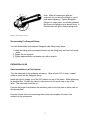
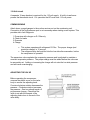
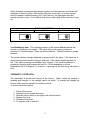
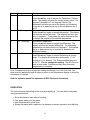
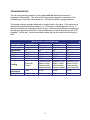
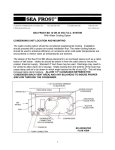
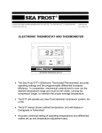
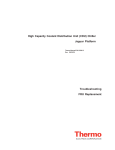
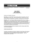
148 OLD CONCORD TURNPIKE BARRINGTON, NH 03825 USA
TEL (603) 868-5720
FAX (603) 868-1040
E-Mail:[email protected]
SEA FROST BAIT FREEZER
BF1 ~ BF2 ~ BF3 ~ BF5
The Sea Frost Bait Freezer system consists of:
•
•
•
•
•
•
1-800-435-6708
www.seafrost.com
Cold Plates or Wrapped Box Liner (hidden cooling coils built into boat)
Refrigerant Control Valve
Copper Connecting Lines
Bullet Drier
Compressor / Condensing unit
Thermostat
1
OPERATION
With the thermostat in the “on” position, the compressor, fan, and pump (if equipped)
will operate. Ten minutes after starting the compressor the area near the valve or the
top of a hidden coil box will begin to cool and frost.
If you do not observe cooling, with the compressor and fan running, switch off
the unit to avoid damage.
After several hours the box temperature will cool to well below freezing.
The first plate or the top section of a wrapped box will cool first. Because it freezes first,
all the moisture suspended in the air within the box condenses and freezes at this plate.
Frost is not a good indication of proper operation; check the temperature with a
thermometer. When the box and contents cool to the desired setting, the compressor
and fan will cycle on and off periodically to maintain the set temperature.
CONDENSING UNIT LOCATION AND MOUNTING
The design of the Bait Freezer (BF) allows the air-cooled condensing unit to be placed
in an enclosed space such as a locker or engine room.
Mount the BF level with the compressor at the bottom. It may be bulkhead or platform
mounted.
Installation Requirements
• Never block the inlet nor outlet. Service access and installation requires that
the front and left end (inlet/outlet side) be exposed.
• Provide for driest, coolest air for intake. Use standard 4" duct hose to draw air
in from the cabin area to insure the coolest, driest air supply. Intake ducting from
the exterior of the boat may cause damp salt air to be drawn in which will reduce
unit life. For intake or exhaust through a finished panel, order a flange grill.
• Discharge does not need ducting if a vent in the area allows warm air to
escape. An un-ducted unit in a poorly ventilated small space will heat the air,
lowering the capacity of the unit and possibly causing damage by overheating the
compressor.
• Total combined air duct length for intake and discharge should not exceed
six feet.
2
Water Cooling
Water-cooling is standard on BF2 and BF3 models. Water from an air conditioning
pump manifold can be plumbed into the BF condensing unit and triggered by the 110volt supply labeled "pump" or a dedicated pump can be installed. A flow of two to three
GPM is sufficient. Use of water-cooling is not mandatory; the unit will operate with aircooling only. If the condensing unit is mounted in a confined area with little ventilation,
or in a very hot engine room, water-cooling must be used.
EVAPORATOR PLATE INSTALLATION
Mount the plates on opposite walls as high as possible to take advantage of thermal
convection. Install the plates with the Wellnut, spacers, and screws provided.
Mount Sea Frost plates with the Wellnut hole
fasteners. Use a template or the plate itself to
locate the mounting holes in the box. Drill a 3/16"
pilot hole and then increase this hole to 3/8". Install
the screw into the plate through the spacer then
tighten the screw in the Wellnut. Push the rubber
mounts into the pre-drilled holes. Tighten the
screws.
Figure 1 ~ Wellnut Installation Detail
SWAGELOK FITTINGS
Swagelok fittings come to you completely assembled,
finger-tight, and ready to use.
Do not take apart the fittings before you are ready to
use them; dirt can get into the fitting and cause leaks.
You also risk damaging the threads of the fittings if the
nuts are removed.
This is a double ferrule system. The most common
installation problem encountered with Sea Frost is the
incorrect assembly of the fittings. Assemble all fittings
as shown in figure 2.
Figure 2 ~ Swagelok Fitting Assembly
3
Note: Loosen the nut slightly before assembly, and then retighten with your fingers
before tightening with a wrench. This avoids cross threading.
Swagelok Installation Instructions
1. Always leave two inches of straight, undistorted copper tube leading to all
Swagelok fittings to allow proper connection. Measure the tubing the correct
distance from the end and mark with a pencil. Refer to Table #1.
Table # 1 Scribe Line Measurements
Copper Tubing Diameter
(Inches)
Measurement from the end of the tubing
(Inches)
3/8
5/16
1/4
11/16
5/8
9/16
2. Insert the marked copper tubing, into the Swagelok tube fitting body. See figure 3.
The tubing should rest firmly on the shoulder of the fitting body so that the pencil
mark is flush with the nut. This mark will also show that the tube has not moved
before tightening. Tighten the nut with your fingers. As you tighten the fitting, the
space from the pencil mark to the shoulder increases.
3. Scribe the nut at the six O’clock
position. See figure 4.
Figure 3 ~ Insert Tube into Fitting Body
4. Tighten the nut wrench snug.
Wrench snug is the first point when
the tube cannot be pulled from the
fitting, (when the ferrules tighten
enough to contact the tubing).
5. Hold the fitting body with a back-up
wrench and tighten the nut oneand-one-quarter turns (1¼) from
the scribe mark.
Figure 4 ~ Scribe Fitting at Six O’clock
4
Note: Make all connections with two
wrenches, do not allow the fittings to turn or
twist when tightening. Tighten Swagelok
fittings to a torque spec, not infinite tightness.
Be sure your starting point is wrench snug. A
distorted tube will give a false starting point.
Figure 5 ~ Turn the Nut 1 ¼ Turns
Reconnecting Pre-Swaged Fittings
You can disassemble and retighten Swagelok tube fittings many times.
1. Insert the tubing with pre-swaged ferrules into the fitting body until the front ferrule
seats.
2. Tighten the nut by hand.
3. Tighten approximately one-quarter turn with a wrench.
EXPANSION VALVE
Valve Installation on a Plate System
Trim the tube ends on the plates as necessary. Allow at least 3/4" of clean, straight
tubing to insert into the Swagelok fitting.
Install the valve to supply one of the 3/8” tubes from one of the plates. Either plate may
be supplied first. Position the valve to allow access to the screw cap on top of the
valve. The valve cap should be up.
Connect the jumper line between the remaining tube on the first plate to either tube on
the second plate.
Connect a return line to the remaining tube on the second plate; this return line
connects to the compressor.
5
Valve Installation on a Wrapped Hidden Coil System
Trim the tube ends on the coil as necessary. Allow at least 3/4" of clean, straight tubing
to insert into the Swagelok fitting. Refer to the Swagelok installation instructions on
page three.
Install the valve to supply the top 5/16” tube end on the hidden coil. Position the valve
to allow access to the screw cap on top of the valve. The valve cap should be up.
Connect a return line to the remaining tube end; this return line connects to the
compressor.
BULLET DRIER
Note: Unpack and fit the drier last. This prevents moisture from saturating the
desiccant in the drier.
Use the 5/16" x 1/4" Swageloks to connect the tube from the compressor to the input
side of the drier and connect the output side of the drier to the valve. Note: Arrows are
stamped into the bullet direr showing flow direction.
COPPER TUBE RUNS
Two copper lines connect the plates or wrapped hidden coil, and the compressor; one is
3/8" and the other is 1/4".
Run the 1/4" liquid line between the condensing unit and the expansion valve. You will
fit the bullet drier to this line.
The 3/8" suction line connects the last plate or hidden coil tube end to the suction port
on the BF cabinet.
Run the 1/4" liquid line in contact with the 3/8" suction line for several feet from the
cabinet. Wrap these two tubes tightly together with electrical tape and insulate this
section. This will improve operation and prevent moisture from condensing on the
coldest section of these tubes. Insulating the remaining length of 3/8" return line to the
compressor is not necessary.
After each cut, cap the copper tube ends with the plastic caps until you make the
Swagelok connection. Support the tubing and protect from chafe.
WARNING: The BF unit is shipped pressurized with nitrogen. Before removing the
Swagelok caps on the connection ports, remove the plastic caps on the service valve
covers and depress the valves cores to vent any existing pressure.
6
Compressor Connections
Remove the Swagelok caps from the liquid and suction fittings. Attach the union
bodies. This is a pre-swaged connection, which is 1/4 turn from wrench snug.
Connect the 1/4" line to the condenser fitting and 5/16" line to the compressor. Tighten
these fittings 1 1/4" turns from wrench snug.
Thermostat Location
The thermostat is low voltage and is connected and powered by the transformer in the
compressor cabinet. Mount the thermostat in a convenient location where the sensing
bulb will reach a mounting screw on a plate. It is necessary that the bulb of the sensor
have good thermal contact with the plate. On multiple plate installations, the
thermostat must sense the last plate in the series after the valve.
Thermostat location on a Wrapped Hidden Coil Box
Position the thermostat close enough for the sensing bulb to reach the middle of the
wrapped box. Attach the bulb to the box wall with marine adhesive. Do not drill into a
wrapped box liner for any reason.
The probe temperature is displayed when 110-volt power is available. The probe
temperature is not the cabinet temperature. The probe temperature is always colder
than the cabinet.
Thermostat Wiring - Ranco
The Electronic Temperature Control operates on low voltage (24VAC) supplied by the
transformer in the compressor cabinet.
A 15’ wiring harness is fitted to the thermostat. Use red, blue, and white 16-gauge wire
to extend this harness if a longer length is needed. Attach the wires to the terminal strip
using #8 ring terminals, matching corresponding wire color.
Thermostat Wiring – IR33
The Electronic Temperature Control operates on low voltage (24VAC) supplied by the
transformer in the compressor cabinet. A 20’ 4-wire gray wiring harness is fitted to the
thermostat. Attach the wires to the terminal strip terminals, following colors below. See
wiring diagram on page 7.
Wires from gray harness
Green
White & Red
Black
Terminal strip in compressor cabinet
Red
Blue
White
7
Wiring
The Ranco Electronic Temperature Control operates on low voltage (24VAC) supplied
by the transformer in the compressor cabinet.
A 15’ wiring harness is fitted to the thermostat. Use red, blue, and white 16-gauge wire
to extend this harness if a longer length is needed. Attach the wires to the terminal strip
using #8 ring terminals, matching corresponding wire color.
RANCO THERMOSTAT WIRING
IR33 THERMOSTAT WIRING
8
110-Volt circuit
A separate 15-amp breaker is required for the 110-volt supply. A built in transformer
powers the thermostat circuit. For operation the BF must have 110-volt power.
COMMISSIONING
Attach clean, purged gauges to the suction service port on the condensing unit.
Connection to the high-pressure port is not necessary when starting a new system. This
provides aid in fault diagnosis.
1. Pressurize with nitrogen or R-134a only
2. Check for leaks
3. Evacuate
4. Charge
•
•
This system operates with refrigerant R-134a. The proper charge (and
maximum charge) is 12 ounces.
The refrigerant may be liquid-fed into the low side after evacuation, before
the compressor is operated.
The expansion valve regulates the evaporator pressure and is adjusted to maintain a
constant evaporator pressure. The proper charge must be added before the valve can
be accurately set. Adding or increasing the charge will not raise the low side pressure
and will cause overcharging.
ADJUSTING THE VALVE
Before operating the compressor,
unscrew the plastic cover on the valve
body to access the adjusting knob.
Counter-clockwise rotation decreases the
pressure. Clockwise rotation increases
the pressure. One turn should equal a 2
psi pressure change. Check that the
valve is set with the threads of the
adjusting knob close to the end of the
valve body.
9
Start the compressor. The valve must be adjusted to a 0 to 4 psi reading on the low
side gauge port. Be sure your gauge is set at O before hook-up. Allow several minutes
between each adjustment. Replace the cap after each adjustment to prevent moisture
from forming on the adjusting knob; the moisture will freeze and cause the valve to
malfunction. The valve must be dry before final cap replacement. Operate for 30
minutes to confirm proper valve setting and operation.
To clear the valve of dirt or chips if adjustment is not possible, turn the valve adjustment
knob clockwise about 3 turns momentarily, and then back to the proper setting while the
compressor is running. Do not leave the valve in the open position, which causes high
backpressure and may cause the compressor to overload.
After satisfactory adjustment turn off the thermostat. Wait until the pressure equalizes
on both gauges before you disconnect the gauges and then recap the service ports.
When the valve is dry, insulate the valve body with a piece of insulating sleeve and
wrap it with cork tape; this will prevent condensation. Insulating the valve is not
necessary if it is in the box. The constant pressure valve sets the refrigerant boiling
point and the pressure setting will indicate the minimum temperature that the BF system
can obtain. Set the valve pressure at the lowest possible pressure setting that will cool
the box. Problems occur when the pressure is high and the thermostat is set low; the
thermostat will not be satisfied.
READING THE SIGHT GLASS
With the compressor operating, a clear sight glass indicates a sufficiently charged
system. To determine the meaning of "clear", view the sight glass when the system is
off. This is a "clear" glass.
WARNING: A clear sight glass can also indicate a completely empty system.
Anytime the compressor is started, white foam should appear in the sight glass
indicating the presence of refrigerant. The foam may disappear quickly. If foam is
observed and the system is not cooling, the system is empty. Do not operate the
system in this empty condition. Operation in this mode will ruin the compressor. Turn
off the main breaker to the control panel until the system can be properly leak tested
and recharged.
Fast moving white foam with the compressor operating indicates an insufficient charge
level. Watch closely for a transition from foam to total liquid, (indicated by a clear sight
glass). This transition point can be missed if not given proper attention. The sight glass
may show large bubbles even when the charge is sufficient, so it is important to
differentiate between "foam" and "bubbles". The foam condition has velocity and
direction; the bubbles are large, temporary, and nearly stationary. Do not try to chase
away these larger bubbles with more refrigerant; overcharging will occur. Air in the
system may give a false sight glass reading, which could lead to overcharging. If in
10
doubt, discharge a suspected overcharged system to continuous foam and slowly add
refrigerant to clear the glass. Monitor the sight glass continually. In a warm system,
when the cabinet is above freezing (32.F) upon start-up, the sight glass may take
several minutes to clear. A cold cabinet may show a clear glass within seconds of startup.
Clear or Empty
SIGHT GLASS DETAIL
Stationary Bubbles
Foam (Low Charge)
Troubleshooting note: The operating pressure of the system will not indicate the
amount of refrigerant in the system. The valve will not give proper operation or
pressure if it is undercharged. Check the valve scribe line. It should correlate to gauge
pressure.
The system requires enough refrigerant to supply liquid to the valve. If the valve has a
steady hissing sound then the charge is sufficient. If the valve is sputtering then it is
low. If the valve is making a noticeable roar it is empty. If the low side pressure is
properly set the high side pressure will be 80 to 135 psi depending on the air
temperature (50 to 95 degrees F.) at the unit. Upon start up the valve body will begin to
frost.
THERMOSTAT OPERATION
The thermostat is pre-set and locked at the factory. When locked the keypad is
disabled and changes to the settings cannot be made. To change the settings the
lockout switch must be placed in the unlock position.
To access the lockout switch:
1.
2.
3.
4.
5.
6.
Switch off the power.
Remove the four screws and cover.
Slide the lockout switch to the right to the unlock position.
Replace the cover.
Re-power the system.
To program refer to table # 2.
11
Step
1
Display
F or C
2
S1 (blinking)
3
DIF 1 (blinking)
4
C1 / H1
Description
Fahrenheit or Celsius Scale
Press the set key once to access the Fahrenheit / Celsius
scale. The display will show the current status, either F for
degrees Fahrenheit or C for degrees Celsius. The
thermostat has been pre-set at the factory for Fahrenheit.
Press the up or down arrow key to choose between the F
and C.
Setpoint Temperature
Press the set key again to access the setpoint. The display
will show the current set point. The setpoint has been preset to 0 degrees F. Press either the up or down arrow key
to change the setpoint to the desired temperature.
Differential Temperature
Press the set key again to access the differential. The
display will show the current differential. The differential
temperature has been pre-set at 5 degrees F. Press either
the up or down arrow key to increase or decrease the
differential setting.
Cooling or Heating Mode
Press the set key again to access the heating or cooling
mode. The display will show the current mode. C1 for
cooling or H1 for heating. The Thermostat has been preset for C1. Do not change this setting. The BF does not
work in heat mode. Press the set key once more and
programming is complete.
Note: Pressing the set key accepts the setting and brings you to the next step. You
must push the set key through all steps to return to the temperature display to allow the
compressor to operate.
Refer to separate manual for operation of IR33 Electronic thermostat.
DEFROSTING
The unit will require defrosting as the frost layer builds up. You can defrost the plates
using several methods:
•
•
•
•
Allow the plates to warm above freezing.
Pour warm water over the plates.
Heat the plates with a hair dryer.
Scrape the plates with a spatula or ice scraper to remove excessive frost build up.
12
TROUBLESHOOTING
The low side operating pressure of the system will not indicate the amount of
refrigerant in the system. The valve will not give proper operation or pressure if it is
undercharged. Check the valve scribe line. It should correlate to gauge pressure.
The system requires enough refrigerant to supply liquid to the valve. If the valve has a
steady hissing sound then the charge is ok. If the valve is sputtering then it is low. If
the valve is making a noticeable roar it is empty. If the low side pressure is properly set
the high side pressure will be 80 to 135 psi depending on the air temperature (50 to 95
degrees F.) at the unit. Almost immediately upon start up the valve body will begin to
frost.
Bait Freezer Specifications
BF 1
Amp Start (LR) 28
A.C. amp draw 3.8 @ 110 volts
1/4
Horsepower
760 @ -10 F.
BTU per hour
16"
Height
14.5"
Width
7.5"
Depth
Cooling
Compressor
unit weight
Refrigerant
BF 2
28
3.8 @ 110 volts
1/4
760 @ -10 F.
16"
14.5"
7.5"
Ducted Air and
Water Cooled
(remote water
pump required)
BF 3
30
4 @ 110 volts
3/8
930 @ -10 F.
16"
14.5"
7.5"
Ducted Air and
Water Cooled
(remote water
pump required)
BF 5
38
5-9
1/2
1400 @ -10 F.
16"
14.5"
7.5"
Ducted Air and
Water Cooled
(remote water
pump required)
36 lbs
38 lbs
42 lbs
49 lbs
134a
134a
134a
134a
Ducted Air
Cooled
13
BAIT FREEZER WITH WRAPPED BOX LAYOUT
14
Figure 9 ~ Wrapped Box Layout
BAIT FREEZER WITH PLATES LAYOUT
15
Figure 10 ~ Plate Layout
16