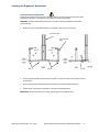
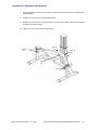
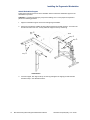
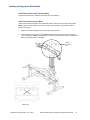
1
® Genesys™ Ergonomic Workstation—G110 & G111 Series Eaton® Profile ® Eaton Profile® Genesys™ Dual-Lift Ergonomic Workstation G110 and G111 Series ® Eaton Raised Floor Grommets—FG76, FG118 ◦ ◦ 90 and 120 Dual-Lift Ergonomic Workstations Installation Guide © Copyright 2011 Eaton Corporation, Worcester, MA, USA. All rights reserved. Information in this document is subject to change without notice. No part of this document may be reproduced or transmitted in any form or by any means, electronic or mechanical, for any purpose, without the express written consent of Eaton. Eaton and Profile are registered trademarks and Genesys is a trademark of Eaton Corporation or its subsidiaries and affiliates. Phillips is a registered trademark of Phillips Screw Company. Torx is a registered trademark of Textron, Inc. All other trademarks are the property of their respective owners. Table of Contents About this Guide Audience General Conventions Documentation vii vii viii 1 Before you Begin Introduction Important Safety Information Site Preparation Tools you Will Need Fasteners you Will Be Using Washers and Grommets you Will Be Using 1 1 1 2 2 3 2 Pre-Installation Preparation and Planning Prerequisites Installation Overview/Checklist Tools you Will Need Fasteners you Will Be Using Unpack the Box Contents Workstation Components Lifts Covered in this Manual 3 5 5 5 5 6 7 8 Installing the Dual-Lift Workstation Introduction Install the Rear Lift Column Assembly Attach Lift Column to Base Assembly Install the Front Lift Column Assembly Attach Leg Assembly to Feet Attach Leg Assemblies to Base Attach Leg and Base Support Covers Level Assembled Components Attach Lower Frame Attach Workstation Support Install Rear Surface and Trim Assembly Attach Rear Surface Support Beam Attach Center Column Cable Chains Drill Holes for Flat Panel Display Support Attach Rear Surface Trim Panels Attach Rear Surface Install User Surface and Components Attach User Surface Check and Adjust Workstation to Maintain Proper Spacing Attach Left Cable Chain to User Surface Attach Lift Control Box and Operator Control Pad Route Cables Install the Rear Cover Initialize the System Installation Options for the G111 Series Attach Keyboard Tray 4 Aligning the Workstation to the Core v Eaton Profile Genesys Dual-Lift Ergonomic Workstation Installation 9 10 10 12 12 13 14 16 17 19 20 20 21 22 23 24 25 25 26 27 28 29 31 32 33 33 35 wwww.eaton.com/powerquality 11-41 06-2011 5 Service and Support Troubleshooting Lift Freezes Error Code Appears on Control Pad Technical Support Sales Representatives Local US Representatives Eaton Worcester Office Latin America, Central/South America & The Caribbean International Distribution Documentation wwww.eaton.com/powerquality 11-41 06-2011 Eaton Profile Genesys Dual-Lift Ergonomic Workstation Installation 37 37 38 38 38 38 38 39 39 40 vi About this Guide This document describes how to install the Profile® Genesys™ Dual-List Ergonomic Workstation. The Profile Genesys Workstation is an ergonomic solution designed for command and control environments such as Emergency Operations Centers, Network Operations Centers, Process Control Environments, Medical Imaging Reading Rooms, and more. Audience This document is intended for installers and/or qualified personnel who are installing the Profile Genesys Dual-Lift Ergonomic Workstation. General Conventions Before you start the installation process, it is important to understand the conventions used in this publication. Convention Bold type Italic type Underlined type UU 1. Numbered lists ACRONYMS Meaning Indicates notes, cautions or warnings that provide important information. Failure to follow these warnings may cause personal injury and/or product damage. Indicates titles of publications or information that the user must supply, such as filenames (if applicable). Underlined type indicates links (if applicable). Indicates procedures that you must follow in a sequential order. Acronyms are defined at the first occurrence in the document. The acronym definition appears first followed by its acronym in parenthesis. For example: electrostatic discharge (ESD). CAUTION: Failure to comply with safety standards in handling the equipment could result in the risk of electric shock. IMPORTANT: Refer to your manual for additional information such as important operating and maintenance instructions. vii Eaton Profile Genesys Dual-Lift Ergonomic Workstation Installation wwww.eaton.com/powerquality 11-41 06-2011 About this Guide Documentation This document can be obtained from our website at http://www.wrightline.com by following this procedure: 1. 2. 3. Click on the “Library” icon. Click on the “Installation Manuals” link, and then select the “Command/Control” option. Under the “Command/Control” section, click on the “Profile Advanced Console System” option. For additional, related information pertaining to this product, refer to these manuals located in the Command/Control Installation Manual section of the Wright Line website. This Document… Profile Genesys Ergonomic Workstation Operator’s Manual Profile Flat Panel Console System Installation Manual DeskPower DB4/DL4 Systems Installation Manual Includes this information. Instructions on how to program, operate, and troubleshoot the workstation. Additional installation instructions on ergonomic workstations. Mounting and operation of control box and desk panel equipment. Motor-Control for Height-Adjustable Desks Installation Manual Installation, start-up, and operation instructions for the Motor-Control box for height-adjustable desks. DESKLINE DL2 and CBD4, CBD5, CBD6 Systems User Manual Mounting the control box and electrical connection of the lift and control box. wwww.eaton.com/powerquality 11-41 06-2011 Eaton Profile Genesys Dual-Lift Ergonomic Workstation Installation viii Chapter 1 Before you Begin Introduction The Profile Genesys Dual-Lift Ergonomic Workstation is an ergonomic solution designed for command and control environments such as Emergency Operations Centers, Network Operations Centers, Process Control Environments, Medical Imaging Reading Rooms, and more. This workstation solution accommodates all computing, networking, and electrical cabling required in a modern command and control environment. The dual lift surfaces allow users to adjust their working postures to comply with the most current ergonomic recommendations. The rear surface and user surface are electronically and independently adjustable. This document describes how to install the Profile Genesys Dual-Lift Ergonomic Workstation in a work environment. CAUTION: To prevent personal injury and product damage, it is strongly recommended that the unpacking, moving, and assembly processes be performed by two or more people. Important Safety Information Please follow these safety guidelines as you unpack, move, and assemble the components of the workstation. Adherence to these guidelines will prevent personal injury and potential product damage. When lifting units, there should be at least one person for every 40 lbs. of weight to be lifted. Do not, under any circumstance, stand on the Profile workstation. Do not stand on Profile workstations to load monitors. Site Preparation It is the customer’s responsibility to clear and prepare the site before installing the workstation. Generally, site preparation includes the following actions, which are provided as a guideline only and not intended as a complete list of site preparation tasks. Access to site drawings to determine where workstation will be installed Clear the area to accommodate the workstation Tape off the floor where workstation is going to be installed Ensure that power requirements are met In this Chapter Refer to the following table for information on a specific topic. Topic Important Safety Information Site Preparation Tools you Will Need Fasteners you Will Be Using Washers and Grommets you Will Be Using 1 Eaton Profile Genesys Dual-Lift Ergonomic Workstation Installation See Page # 1 1 2 2 3 www.eaton.com/powerquality 11-41 06-2011 Before you Begin Tools you Will Need The following tools are required to successfully install the workstation. Common installation tools 3/8” socket TORX driver for M8x36 flathead screws #1 and #2 Phillips head screwdriver Powered driver Spirit (bubble) level Hole saw, 2-1/2” diameter 11/16” nut driver (or socket wrench) 5/8” nut driver (or socket wrench) 5/32” Allen wrench 1-3/8” open end wrench (for leveling glide adjustment) Phillips head screwdriver Rubber mallet Fasteners you Will Be Using Following is an illustration of the fasteners and screws that are provided in the Lift assembly box (provided in kit labeled PROKIT43-thru-PROKIT46). Front and side views are shown. For a complete list of parts, refer the section, “Unpack the Box Contents” in Chapter 2. Item Screws 3 8 12 10 15 5 14 11 7 17 16 Front View Description #8-32 x 3/8” flathead, thread cutting screw Pan head thread form screw #10-32 x 3/8” M6 x 10mm Phillips pan head screw 1/4-20 x 1/2” pan head screw Phillips pan head screw 1/4-20 x 1/2” hex washer thread form Phillips pan head screw M6 x 20MM Phillips pan head screw #10A x 1” Phillips pan head screw M8x36 flathead Torx (supplied with DL2 by LINAK) Hex head, 3/8-16 x 2.5” bolt Part Number 18618 66714 91503 83105 97409 54348 97408 85234 62071 N/A 98129 Side View www.eaton.com/powerquality 11-41 06-2011 Eaton Profile Genesys Dual-Lift Ergonomic Workstation Installation 2 Before you Begin Washers and Grommets you Will Be Using Following is an illustration of the washers and grommets that are provided in the Lift assembly box (provided in kit labeled PROKIT43-thru-PROKIT46). Front and side views are shown. For a complete list of parts, refer the section, “Unpack the Box Contents.” Item Description Part Number Washers and Plugs 4 9 6 13 Lock washer, helical 3/8” W Series washer 1.5” hole plug Heyco Snap bushing 1 2 Grommet, base Grommet, top 18950 82785 60906 97492 Grommets 3 Eaton Profile Genesys Dual-Lift Ergonomic Workstation Installation 94174 94175 www.eaton.com/powerquality 11-41 06-2011 Chapter 2 Pre-Installation Preparation and Planning This chapter describes the preparation and planning involved prior to installing the Profile Genesys Dual-Lift Ergonomic Workstation. Prerequisites The core-to-core assembly must be complete before the ergonomic workstation installation can occur. For instructions on how to install the core-to-core assembly, refer to the Profile Flat Panel Console System Installation Manual at our website, http://www.wrightline.com. IMPORTANT: Build the workstation independent from the core. Once the core assembly is complete, then the fully-assembled workstation can be aligned with the core per the instructions in this manual. Installation Overview / Checklist The following checklist is intended to be a quick reference to ensure all hardware components of the Profile Genesys Dual-Lift Ergonomic Workstation are installed in the proper order. For further information on any of these steps, refer to the detailed instructions in the corresponding section of this manual. Topic Install the Rear Lift Column Assembly Install the Front Lift Column Assembly Install the Rear Surface and Trim Panels Install the User Surface and Components Installation Options for the G111 Series Refer to.. 10 12 20 25 33 Tools you Will Need Refer to the tools listed in Chapter 1 to properly install the workstation. Fasteners you Will Be Using Refer to Chapter 1 for a list of fasteners you will be using to install the workstation. In this Chapter Refer to the following table for information on a specific topic. Topic Prerequisites Installation Overview / Checklist Tools you Will Need Fasteners you Will Be Using Unpack the Box Contents Workstation Components Lifts Covered in this Manual 5 Eaton Profile Genesys Dual-Lift Ergonomic Workstation Installation See Page # 5 5 5 5 6 7 8 wwww.eaton.com/powerquality 11-41 06-2011 Pre-Installation Preparation and Planning Unpack the Box Contents Before you begin the installation and assembly process, ensure that the following parts are included in your shipment. Refer to the illustration on the next page for a diagram of all system components included in the PROKIT46 assembly (60” x 60” workstation). If any parts are missing, then contact Technical Support at [email protected]. Item 1 2 3 4 5 6 7 8 9 10 11 12 13 14 15 16 17 18 19 20 21 22 23 24 25 26 27 28 29 30 31 32 33 34 35 36 37 38 39 40 41 42 43 44 45 46 47 48 49 50 Part Qty Profile Dual Genesys Lift (varies based on model) Base, Grommet Top, Grommet Screw #8-32 x 3/8” Flathead Thread Cutting Washer, Lock, Helical Screw, ¼-20x1/2 Hex Washer HD Hole Plug, 1.5” Screw, #10A x 1.00 Phillips Pan Head Screw, Pan Head Thread Form Leveler Washer – 3/8” W Series Screw, ¼-20 x ½” Phillips Pan Head Screw M6 x 20MM Phillips Pan Head AC Power Cord 3m Motor Control Cable, 1000mm (39”) LINAK CBD4 – 3 Lift, 120Vac Motor Control Cable, 2000mm (78”) Screw – M6 x 10MM Phillips Pan Head LINAK, DL6 Desklift, 1200N (270 lb) Motor Control, Extension Cable E-Chain, 41 Links E-Chain, 53 Links Screw, Phillips Pan Head Screw, Philip Pan Head Bushing – Heyco Snap Bolt, Hex Head, 3/8-16 x 2.5 Label – Eaton Profile Top Cap Compass Foot WLD, Beam Support WLD, Base WLD, Foot, DL6 WLD, Frame, User Deck WLD, Lower Frame Bracket, Cable Chain Mounting End Cap Plastic Cover Base Support Cover Flat Panel Display Deck Workstation Bracket, 17 Power Strip Mount Toe Cap – Next Generation Assembly, LINAK, DL2 Plastic Cover Front Cover, Rear Surface Side Cover, Rear Surface Rear Cover, Rear Surface Cover, Leg, Right Cover, Leg, Left Attachment Bracket, Right Attachment Bracket, Left Workstation, 90-48x42x48, User Surface Screw supplied with DL2 by LINAK wwww.eaton.com/powerquality 11-41 06-2011 1 2 2 15 24 8 1 49 38 10 2 2 8 1 2 1 1 8 2 1 2 1 10 4 2 2 1 2 1 1 2 1 1 1 2 1 1 1 1 4 1 1 1 2 1 1 1 1 1 1 8 Part Number See P/Ns List 94174 94175 18618 18950 54348 60906 62071 66714 68435 82785 83105 85234 89630 89631 90066 90071 91503 96241 96779 97352 97362 97408 97409 97492 98129 98137 17706X 20040X 20041X 20107X Varies Varies 20546X 1554X 20756X 20042X Varies 21355X 21356X 22118X 22650X 21614X 21615X 21616X Varies Varies 22156X 22157X Varies N/A Eaton Profile Genesys Dual-Lift Ergonomic Workstation Installation 6 Pre-Installation Preparation and Planning Workstation Components The following diagram illustrates all components that are included in the Profile Genesys Dual-Lift Ergonomic Workstation shipment. Refer to the table on the previous page for a description and quantity of each component. 7 Eaton Profile Genesys Dual-Lift Ergonomic Workstation Installation wwww.eaton.com/powerquality 11-41 06-2011 Pre-Installation Preparation and Planning Lifts Covered in this Manual The following table lists the Profile Genesys Ergonomic Lifts that are covered in this manual. Part Dual 48” x 48”, 90º Core Only Dual 48” x 48”, 90º Core Only, Tilt Keyboard Dual 48” x 48” 90º, Stand Alone Dual 48” x 48” 90º, Tilt Keyboard, Stand Alone Dual 60” x 60”, 90º Dual 60”x 60”, 90º Tilt Keyboard Dual 72” x 72”, 90º Dual 72” x 72”, 90º, Tilt Keyboard Dual 30” x 30” x 30”, 90º, Stand Alone Dual 30” x 30” x 30”, 90º, Tilt Keyboard, Stand Alone Dual 30” x 30” x 30”, 90º, CO Dual 30” x 30” x 30”, 90º, Tilt Keyboard, Core Only Dual 30” x 36” x 30”, 90º Dual 30” x 36” x 30”, 90º, Tilt Keyboard Dual 36” x 36” x 36”, 90º Dual 36” x 36” x 36”, 90º, Tilt Keyboard Dual 42” x 42” x 42”, 90º Dual 42” x 42” x 42”, 90º, Tilt Keyboard Dual 48” x 42” x 48”, 90º Dual 48” x 42” x 48”, 90º, Tilt Keyboard Dual 48” x 48”, 120º, Core Only Dual 48” x 48”, 120º, Tilt Keyboard, Core Only Dual 48” x 48”, 120º, Stand Alone Dual 48” x 48”, 120º, Tilt Keyboard, Stand Alone Dual 60” x 60”, 120º, Core Only Dual 60” x 60”, 120º, Tilt Keyboard, Core Only Dual 60” x 60”, 120º, Stand Alone Dual 60” x 60”, 120º, Tilt Keyboard, Stand Alone wwww.eaton.com/powerquality 11-41 06-2011 Part Number G110C4848-A G111C4848-A G110B4848-A G111B4848-A G110A6060-A G111A6060-A G110A7272-A G111A7272-A G110B303030-B G111B303030-B G110C303030-B G111C303030-B G110A303630-B G111A303630-B G110A363636-B G111A363636-B G110A424242-B G111A424242-B G110A484248-B G111A484248-B G110C4848-C G111C4848-C G110B4848-C G111B4848-C G110C6060-C G111C6060-C G110B6060-C G111B6060-C Eaton Profile Genesys Dual-Lift Ergonomic Workstation Installation 8 Chapter 3 Installing the Dual-Lift Workstation Introduction This chapter describes how to install the components of the dual-lift workstation. Installation tasks include the following: Installing the rear lift column assembly Installing the front lift column assembly Leveling assembled components Installing the rear surface and trim assembly Installing user surface and components Installing optional modules (if applicable) In this Chapter Refer to the following table for information on a specific topic. Topic Install the Rear Lift Column Assembly Attach Lift Column to Base Assembly Install the Front Lift Column Assembly Attach Leg Assembly to Feet Attach Leg Assemblies to Base Attach Leg and Base Support Covers Level Assembled Components Attach Lower Frame Attach Workstation Support Install the Rear Surface and Trim Assembly Attach Rear Surface Support Beam Attach Center Column Cable Chains Drill Holes for Flat Panel Display Supports Attach Rear Surface Trim Panels Attach Rear Surface Install the User Surface and Components Attach User Surface Check and Adjust Workstation to Maintain Proper Spacing Attach Left Cable Chain to User Surface Attach Lift Column Control Box and Operator Control Pad Route Cables Install the Rear Cover Initialize the System Install Options for the G111 Series (if applicable) 9 Eaton Profile Genesys Dual-Lift Ergonomic Workstation Installation See Page # 10 10 12 12 13 14 16 17 19 20 20 21 22 23 24 25 25 26 27 28 29 31 32 33 wwww.eaton.com/powerquality 11-41 06-2011 Installing the Ergonomic Workstation Install the Rear Lift Column Assembly Follow these procedures to assemble the rear lift column assembly. Attach Lift Column to Base Assembly Follow these instructions to attach the rear lift column to the base. NOTE: This procedure requires a team of two people to support and stabilize the lift column and base until the fasteners are secure and the assembly is resting on the base. Raise the leveling feet on the base cover to 3/4” before you begin the assembly process. 1. Turn the lift column upside down as shown in the illustration below. Base Step (2x) Base Cover DL2 Front of Lift Shown 2. Remove the two screws as shown and retain for later use. 3. Slide the base cover over the lift column as shown above. 4. Hold the lift column in a vertical position and align the four holes on the base with the holes on the DL2 lift column. Using the four lock washers (18950) and four TORX M8x35 flathead screws, loosely attach the base to the lift column as shown in the following illustration. wwww.eaton.com/powerquality 11-41 06-2011 Eaton Profile Genesys Dual-Lift Ergonomic Workstation Installation 10 Installing the Ergonomic Workstation NOTE: Keep the assembly vertical at all times. Do not fasten base cover at this time. Step (4x) Base Lift Column 5. Tighten the screws in an X pattern as shown below, being careful not to over-tighten. The lift column is made of aluminum and the screw holes are susceptible to being easily stripped. Step 6. Flip over the assembly so that the base rests on the floor. Move and position the assembly close to the final installation location. The rear lift column assembly is complete. Proceed to the next section for instructions on installing the front lift column assembly. 11 Eaton Profile Genesys Dual-Lift Ergonomic Workstation Installation wwww.eaton.com/powerquality 11-41 06-2011 Installing the Ergonomic Workstation Install the Front Lift Column Assembly Follow these procedures to install the front lift column assembly. Attach Leg Assembly to Feet Follow these instructions to attach the foot assembly (left and right) to its respective DL6 leg assembly (left and right). NOTE: The foot bracket and the top of the leg assembly must both be oriented to its respective foot - left with left and right with right. NOTE: Make sure the levelers are extended at least 3/4” before you begin the assembly process. 1. Insert the right leg assembly into the right foot assembly as illustrated below. Foot Assembly Leg Assembly 2. Insert four M6 x 20MM Phillips pan head screws (85234) with four lock washers (18950) through the top of the right leg assembly and tighten as illustrated below. Step (4x) Leg Assembly 3. Repeat steps 1 and 2 with the left leg assembly and the left foot assembly (see illustration above). wwww.eaton.com/powerquality 11-41 06-2011 Eaton Profile Genesys Dual-Lift Ergonomic Workstation Installation 12 Installing the Ergonomic Workstation Attach Leg Assemblies to Base Follow these instructions to attach the left and right leg assembly to its respective base support. 1. Align the right leg assembly with the right base support. Leg Assembly Support Cover Leg Assembly Base Supports (Left and Right) 2. Insert eight Phillips head thread form screws (66714) and tighten as shown below. Step Step (8x) 13 3. Repeat step 1 to align the left leg assembly to the left base support. 4. Repeat step 2 to tighten the screws to the left leg assembly. Eaton Profile Genesys Dual-Lift Ergonomic Workstation Installation wwww.eaton.com/powerquality 11-41 06-2011 Installing the Ergonomic Workstation Attach Leg and Base Support Covers Follow these instructions to attach the base support cover (left and right) to its respective base support (left and right). 1. Attach the base support cover to the right base support. 2. Insert and tighten six Phillips head thread form screws (66714) through the base support cover, securing the cover to the base support as illustrated below. Four of the Phillips head screws are located at the bottom of the cover and two at the top end as illustrated below. 3. Repeat steps 1 and 2 to secure the left cover to the left base support as illustrated below. Step (6x) Base Support Cover Step 4. Attach the lift base support cover to the base as shown in the illustration on the following page. wwww.eaton.com/powerquality 11-41 06-2011 Eaton Profile Genesys Dual-Lift Ergonomic Workstation Installation 14 Installing the Ergonomic Workstation 5. Insert four Phillips head thread form screws (66714) in the screw holes on the lift base cover and tighten (see the illustration below). 6. Re-install the two lift column screws you removed and retained earlier to the base as shown below. Step Lift Base Cover Step (4x) Step (2x) Step Step You have successfully attached the leg and base covers for the Profile Genesys Ergonomic Workstation. Proceed to the next section for instructions on leveling the assembled components. 15 Eaton Profile Genesys Dual-Lift Ergonomic Workstation Installation wwww.eaton.com/powerquality 11-41 06-2011 Installing the Ergonomic Workstation Level Assembled Components Follow these instructions and refer to the illustration below to level the components that have been assembled at this point, including the leg assemblies as well as the lift column. WARNING: Failure to follow these instructions may result in improper installation and potential product damage. 1. Make sure the lift column base levelers are extended at least 3/4” prior to leveling. Lift Column (DL2) Leg Assemblies (DL6) Step Step Step Step Step 2. Using a spirit level (bubble level) instrument, level the unit front to back as well as side to side as shown above. 3. Ensure that both leg assemblies (DL6) are plumb 90º to the base as illustrated above. 4. Ensure the lift column (DL2) is plumb 90º to the base as illustrated above. IMPORTANT: Do not proceed to the next step until the product is completely level. wwww.eaton.com/powerquality 11-41 06-2011 Eaton Profile Genesys Dual-Lift Ergonomic Workstation Installation 16 Installing the Ergonomic Workstation Attach Lower Frame Follow these instructions and refer to the illustration below to attach the workstation support frame to the assembled components. It is very important to perform these instructions in the sequential order noted here; otherwise, failure to do so may result in personal injury or product damage. CAUTION: To prevent personal injury and product damage, two or more people are required to perform the following procedure. 1. From the sides of the lift column, remove the two pre-installed Phillips screws (96983) as shown in illustration below. 2. On the middle front of the lift column, loosen the center pre-installed Phillips screw (96983) by approximately 0.125 inch. IMPORTANT: Do not tighten any screws until the frame is level and aligned! Step Step Step (2x) Step Step Step (2x) Step (2x) 17 Step (2x) 3. Hook the lower frame to the column using the loosened center support Phillips screw (96983). 4. At the left leg support, insert two Phillips machine screws (97409) and two lock washers (18950). Align edges square to the DL6 mounting plate. 5. At the right leg support, insert two Phillips machine screws (97409) and two lock washers (18950). Align edges square to the DL6 mounting plate. 6. Insert two Phillips screws (96983) through the frame into the column. Eaton Profile Genesys Dual-Lift Ergonomic Workstation Installation wwww.eaton.com/powerquality 11-41 06-2011 Installing the Ergonomic Workstation 7. Level and align the lower frame, then tighten all inserted screws in the sequence noted here and illustrated below. 8. Tighten four (4) screws on the leg assemblies (DL6). 9. Tighten two (2) side screws on lift column (DL2). Ensure unit is properly aligned, level and plumb 90 degrees to all lifts and legs. 10. Tighten one front screw on the lift column (DL2). Step Step (4x) Step (2x) Step (1x) Step wwww.eaton.com/powerquality 11-41 06-2011 Eaton Profile Genesys Dual-Lift Ergonomic Workstation Installation 18 Installing the Ergonomic Workstation Attach Workstation Support Follow these instructions and refer to the illustration below to attach the workstation support to the assembled components. CAUTION: To prevent personal injury and product damage, two or more people are required to perform the following procedure. 1. Align the workstation support over the left and right leg assemblies. 2. Using four lock washers (18950) and four Phillips head screws (91503) per side two sets in the front and two sets in the rear loosely attach the support to the top of each leg. Step (4x) Step Step Step Step Detail Shown 3. 19 Level the support, then align to the top of each leg and tighten the eight (8) screws that were inserted in step 2. See illustration above. Eaton Profile Genesys Dual-Lift Ergonomic Workstation Installation wwww.eaton.com/powerquality 11-41 06-2011 Installing the Ergonomic Workstation Install Rear Surface and Trim Assembly Follow these instructions to install the rear surface and trim assembly. Attach Rear Surface Support Beam Follow these instructions and refer to the illustration below to attach the rear surface support frame. NOTE: This procedure requires a team of two people to align the beam and stabilize it until the fasteners are secure. 1. Align the rear surface support beam over the top of the lift column. 2. From above the beam, insert four TORX M8x35 flathead screws through the beam into the lift column and tighten. NOTE: Cross-tighten the screws in an X pattern (as shown in the detail view below), being careful not to over tighten. Step See Detail (4x) Detail Shown wwww.eaton.com/powerquality 11-41 06-2011 Eaton Profile Genesys Dual-Lift Ergonomic Workstation Installation 20 Installing the Ergonomic Workstation Attach Center Column Cable Chains Follow these instructions to attach the cable chain bracket and chains. 1. Place the cable chain support bracket to the bottom rear of the rear surface support beam. Rear Surface Support Beam Step Step (6x) Step (6x) Step Cable Chains Step Step (6x) 21 2. From underneath the beam, insert six Phillips thread form screws (66714) through the cable chain bracket into the bottom of the support beam and tighten to attach the support bracket to the rear surface support beam. 3. Attach the top of both cable chains to the rear of the support bracket using three Phillips head machine screws (18618) on each side and tighten. 4. Attach the bottom of both cable chains to the rear of the lower support frame using three Phillips screws (18618) on each side and tighten. Eaton Profile Genesys Dual-Lift Ergonomic Workstation Installation www.eaton.com/powerquality 11-41 06-2011 Installing the Ergonomic Workstation Drill Holes for Flat Panel Display Support Before completing this procedure, refer to the project-specific bill of materials (BOM) and CAD drawings for FPD mount configuration. Individual component installation / assembly instructions for bow arrays and Centris® Cup can be found on the website under their respective part numbers. Based on the pole configuration and the number of FPDs being installed, refer to the table below and follow these instructions to drill the holes for the FPD support. If You Are Installing this Flat Panel Display Configuration… 2 over 2 flat panel displays (see figure below) 3 over 3 flat panel displays 4 over 4 flat panel displays 5 over 5 flat panel displays Then Drill 2-1/2” Diameter Hole Here. 6.00 See this Configuration in Figure Below A 14.15 18.90 B C 2 over 2 Flat Panel Displays Shown Complete the following procedure to drill support holes in the rear surface. 1. Mark the correct existing pre-drilled pilot hole based on the flat panel display configuration noted in the table above. See the figure below for cutout locations. 2. From the bottom of the rear surface, drill two .250” pilot holes completely through the deck using a 1/4 (.250”) inch drill. www.eaton.com/powerquality 11-41 06-2011 Eaton Profile Genesys Dual-Lift Ergonomic Workstation Installation 22 Installing the Ergonomic Workstation 3. From the bottom of the rear surface, drill two holes to approximately .250” diameter through the bottom backer material. This will prevent chipping of backer material. 4. From the top rear surface, use the pilot holes to drill two 2.50” holes down through the laminate and completely through the deck using a 2-1/2” diameter hole saw. Attach Rear Surface Trim Panels Follow these instructions and refer to the illustration below to attach the rear surface trim panels. 1. From the bottom rear surface, insert the front curved panel (22163X or 21616X) into the slot in the bottom front of the deck. Step (2x) Side Panels (2) Step Step (2x) Step (2x) Front Panel Rear Surface 23 2. Insert two Phillips wood screws (62071) through the panel into the rear surface and tighten. 3. From underneath the rear surface, insert a side curved panel (21615X or 22162X) into the slot in the bottom side of the surface as illustrated above. 4. Insert two Phillips wood screws (62071) through the panel into the surface and tighten. 5. Repeat steps 3 and 4 to attach the other side curved panel. 6. Install two (2) thread form (66714) #10-32 screws through front panel into both side panels. Eaton Profile Genesys Dual-Lift Ergonomic Workstation Installation www.eaton.com/powerquality 11-41 06-2011 Installing the Ergonomic Workstation Attach Rear Surface Follow these instructions and refer to the illustration below to attach the rear surface to the rear surface support beam. 1. Align the rear surface above the rear surface beam using the flat panel display poles and/or grommet opening to help with alignment. 2. From the bottom of the rear surface, insert 17 Phillips head screws (62071) through the support beam into the bottom of the surface and tighten. Rear Surface Rear Surface Support Beam Step (17x) www.eaton.com/powerquality 11-41 06-2011 Eaton Profile Genesys Dual-Lift Ergonomic Workstation Installation 24 Installing the Ergonomic Workstation Install User Surface and Components Follow these instructions to install the user surface and components. Attach User Surface Follow these instructions to attach the user surface to the support frame. 1. Align the pre-drilled holes in the bottom of the user surface with the openings in the support frame. 2. Insert the Phillips head wood screws (62071) and tighten. The number of screws may vary depending on the lift size. Step User Surface Support Frame Step (Screw Qty Varies) 25 Eaton Profile Genesys Dual-Lift Ergonomic Workstation Installation Step www.eaton.com/powerquality 11-41 06-2011 Installing the Ergonomic Workstation Check and Adjust Workstation to Maintain Proper Workstation Spacing Follow these instructions to check and adjust the workstation setting (if necessary) to ensure proper spacing between the user surface and the rear surface of the workstation. To check the spacing between the user and rear surfaces, do the following: 1. Extend the user and rear surfaces to their highest setting. 2. Measure the gap between the surfaces to be 1.5”. 3. If the gap is inconsistent, then check if the workstation is level. 4. If the unit is not level, then loosen the three rear lift (DL2) mid screws (2 side and 1 front) on the lower support as illustrated below. Loosen Screws (3x) 5. Adjust the front and back of the rear surface until the gap is uniform and is 1.5”. 6. Tighten the side screws, and then the front screw. www.eaton.com/powerquality 11-41 06-2011 Eaton Profile Genesys Dual-Lift Ergonomic Workstation Installation 26 Installing the Ergonomic Workstation Attach Left Cable Chain to User Surface Follow these instructions and refer to the figure below to assemble and attach the left cable chain to the user surface. 1. From below the user surface, attach the 53-link cable chain (97632) using two Phillips head screws (62071) to the surface. 2. From behind the assembly, attach the cable chain to the lower frame using three Phillips head machine screws (18618). Step (2x) Cable Chain (97362) Step (3x) 27 Eaton Profile Genesys Dual-Lift Ergonomic Workstation Installation www.eaton.com/powerquality 11-41 06-2011 Installing the Ergonomic Workstation Attach Lift Control Box and Operator Control Pad Follow these instructions and refer to the figure below to attach the power control box and power control pad to the bottom of the user surface. 1. From underneath the user surface, attach the lift control box (90066) to the center rear section of the surface. Insert four Phillips wood screws (62071) and tighten. User Surface Power Control Box Step (4x) 2. From the underneath the user surface, attach the operator control pad bracket (96239) to the left front of the surface as shown in the illustration below. NOTE: The control pad can be mounted in different locations under the user deck, depending on the configuration. For instructions on calibrating and operating the control pad, refer to Chapter 5. 3. Insert two Phillips wood screws (62071) and tighten. Power Control Pad Step (2x) 4. Slide the control pad firmly into the support bracket until it clicks into place. www.eaton.com/powerquality 11-41 06-2011 Eaton Profile Genesys Dual-Lift Ergonomic Workstation Installation 28 Installing the Ergonomic Workstation Route Cables Follow these instructions for an overview on how to route cables through the assembled components to a power source. These instructions are intended to provide general guidelines only since configurations may vary. To route cables, do the following: 1. Route the power control cable from the power control switch (96239) through the channel in the workstation support frame to the control box (90066). When routing cables, adhere to these guidelines: a. b. c. 2. The DL2 lift is to be connected to the sockets on the control box by means of the motor cables, which have a 6-pin plug in each end. The mains cable is to be mounted and power switched on. Please note that the control box must only be connected to the voltage stated on the label. The control box earth cable should be mounted on the workstation in a way that ensures good electrical contact. The function of the earth cable is to earth the desk and ground static electricity. The earth connection does not protect other electrical products. Route the power cable from the control box (90066) through the workstation support frame, cable chain, and lower frame to a power outlet. See Port Connections Detail Refer to the following port connections illustration and perform the following instructions to connect each cable to the appropriate port. 29 Eaton Profile Genesys Dual-Lift Ergonomic Workstation Installation www.eaton.com/powerquality 11-41 06-2011 Installing the Ergonomic Workstation 3. Connect the DL6 cable to Port 1 as shown below. 4. Connect the other DL6 cable to Port 2 as shown below. 5. Connect the DL2 cable to Port 3 as shown below. 6. Connect the power cable to the power outlet as shown below. 7. Connect the controllers to the controller port as shown here. Port Connections Detail IMPORTANT: Note the connection port assignment. The workstation will not function unless the lifts are plugged into the correct ports as shown here. 8. Test cable routing and connections. Check all cable routes for pinching and interference. www.eaton.com/powerquality 11-41 06-2011 Eaton Profile Genesys Dual-Lift Ergonomic Workstation Installation 30 Installing the Ergonomic Workstation Install the Rear Cover Once all the cables have been routed, you will need to install the rear cover to the rear surface. To install the rear cover to the rear surface, do the following: 1. Attach the rear cover (21616X) to the rear surface by inserting three (3) #10A x 1” Phillips pan head screws (62071) through the rear cover and into the rear surface and tighten. Rear Surface Rear Cover Step (3x) 2. The rear cover installation is now complete. You have successfully installed the Profile Genesys Ergonomic Workstation. Proceed to the following section for instructions on initializing the system. 31 Eaton Profile Genesys Dual-Lift Ergonomic Workstation Installation www.eaton.com/powerquality 11-41 06-2011 Installing the Ergonomic Workstation Initialize the System To initialize the lift, do the following: 1. On the control pad, press the Down Arrow button until the lift column lowers to the “end-stop” position”. Workstation Model Shown for Illustrative Purposes Only 2. If the controls are not working properly, then refer to the DeskPower DB4/DL4 Systems Guide to ensure the control pad has been properly installed. Refer to the “Documentation” section of this manual for document location. You have now successfully installed and initialized the Profile Genesys Dual-Lift Ergonomic Workstation and it is ready for operation. For additional operational information on how to set and store user positions, adjust the height of the workstation, and switch to a stored memory position, refer to the Profile Genesys DualLift Ergonomic Workstation Operator’s Manual. The Operator’s Manual also includes instructions on how to troubleshoot the workstation should any system malfunction occur. www.eaton.com/powerquality 11-41 06-2011 Eaton Profile Genesys Dual-Lift Ergonomic Workstation Installation 32 Installing the Ergonomic Workstation Installation Options for the G111 Series This section provides instructions on installing the Eaton Profile Genesys G111-Series Ergonomic Workstation with keyboard tray. Skip this section if you are not installing this product. Attach Keyboard Tray If you ordered the keyword tray, then follow these instructions to attach the keyboard tray to the user surface. 1. Attach the keyboard assembly below the front of the user surface by hooking the frame to the user surface support frame. Step (5x) Keyboard Assembly Step (4x) User Surface 33 2. From below the work surface, insert four Phillips screws (92927) through the keyboard tray supports into the user surface support frame and tighten. 3. Insert five Phillips screws (92927) horizontally through the keyboard tray bracket into the front of the user surface support frame and tighten. 4. Initialize the lift by pressing the Down Arrow button on the control pad until the lift column lowers to the “end-stop” position. Eaton Profile Genesys Dual-Lift Ergonomic Workstation Installation www.eaton.com/powerquality 11-41 06-2011 Chapter 4 Aligning the Workstation to the Core Now that the Profile Genesys Dual-Lift Ergonomic Workstation has been successfully installed, you will need to align the workstation to the core as documented below. To install additional system components such as flat panel displays, and so on, refer to the Profile® Flat Panel Console System Installation Manual for detailed instructions. To align the workstation to the core, do the following: 1. Attach the connector base to the lift base, using thread forming screws (54348) as shown in the exploded view below. 2. Connect the base to the core by inserting and tightening four (4) thread forming screws (54348) as shown in the exploded view below. 3. Secure the cover using four (4) #10-32 x 3/8” Pan head swage form screws (66714). 90º Corner Step (4x) See detail below Cover Step (4x) Lift Base Connector Base 35 Eaton Profile Genesys Dual-Lift Ergonomic Workstation Installation Detailed View Step www.eaton.com/powerquality 11-41 06-2011 Aligning Workstation to the Core 4. Connect the lift with connector base to the core via four (4) #1/4-20 screws (53956) and #1/4-20 Kep nuts (18209 ). Step Genesys-Compatible Inside Skin (Fabric, Laminate or Steel) 90º Compound Corner Shown Connector Cover Step (4x) Step Connector Base (G431A903) Genesys Lift (Shown for Reference Only) 5. Install the grommet in the grommet opening in the core as shown below. 6. Route cables from the lift through the grommet opening in the core as shown below. 7. Install connector cover with four (4) screws (66714) as illustrated below. Step Step (4x) 8. Install compatible inside skins. You have now completed the alignment of the workstation to the core. www.eaton.com/powerquality 11-41 06-2011 Eaton Profile Genesys Dual-Lift Ergonomic Workstation Installation 36 Chapter 5 Service and Support If you have any problems with installing or using this product, follow these troubleshooting tips or contact us using one of the methods provided. Troubleshooting If a problem occurs with the system, refer to the “Troubleshooting” section of the Eaton Profile Genesys Ergonomic Workstation Operator’s Manual for troubleshooting tips and corrective actions. If the lift freezes and the workstation is not moving in an upward or downward direction, then re-initialize the system per the instructions noted below. Lift Freezes If the lift freezes and the workstation is not moving in an upward or downward motion, then you will need to re-initialize the system and it should correct the problem. Follow these instructions to re-initialize the lift. To re-initialize the lift, do the following: 1. On the control pad, press the Down Arrow button until the lift column lowers to the “end-stop” position”. Workstation Model Shown for Illustrative Purposes Only In this Chapter Refer to the following table for information on a specific topic. Topic Troubleshooting Lift Freezes Error Code Appears on Control Pad Technical Support Documentation 37 Eaton Profile Genesys Dual-Lift Ergonomic Workstation Installation See Page # 37 37 38 38 40 www.eaton.com/powerquality 11-41 06-2011 Service and Support 2. If the controls are still not working properly, then do one of the following: Refer to the Eaton Profile Genesys Dual-Lift Ergonomic Workstation Operator’s Manual for troubleshooting tips and corrective actions. Refer to the DeskPower DB4/DL4 Systems Guide to ensure the control pad has been properly installed. See the “Documentation” section of this manual for document location. Contact Eaton for Technical Support assistance. Error Code Appears on Control Pad If a problem occurs with the system and an error code displays on the control pad, then refer to the Troubleshooting section of the Eaton Profile Genesys Dual-Lift Ergonomic Workstation Operator’s Guide for a list of error codes and corrective action associated with the error. Technical Support Send an email and detailed description of the problem as well as contact information to Technical Support at [email protected]. Sales Representative Contact an Eaton Sales representative by one of the methods below. Phone: Call us toll free at 800.225.7348 (US Only) or 508.852.4300 Mail: Eaton 160 Gold Star Boulevard Worcester, MA 01606 Email: [email protected] U UU Web: Visit us at http://www.wrightline.com and click on “Contact Us.” Simply complete and submit the form as directed on our web site. Local US Representative To find a sales representative in the area, visit our website at http://www.eaton.com/wrightline.com, and then click on “Contact your local rep for more information.” For US visitors, enter your zip code in the field and click on the Submit button. Eaton Worcester Office Eaton 160 Gold Star Blvd. Worcester, MA 01606 Tel: 508-852-4300 Toll Free: 800-225-7348 Fax: 508-853-8904 www.eaton.com/powerquality 11-41 06-2011 Eaton Profile Genesys Dual-Lift Ergonomic Workstation Installation 38 Service and Support Latin America, Central/South America & The Caribbean Carla Hauschildt Eaton HC20 Box 10723 Juncos, PR 00777 Tel: (787)547-2627 Fax: (508)365-6042 International Distribution Canada TAB Technical Environments 130 Sparks Avenue Willowdale, ON M2H 2S4 Tel: 800-667-4020 Fax: 888-257-5205 Europe ICTroom Company BV Tokyostraat 27-29 1175 RB Lijnden Postbus 9185 1006 AD Amsterdam The Netherlands Tel: 31-(0)-20-820-3000 Fax: 31-(0)-20-820-3010 Malaysia Quantum Special Sdn Bhd 2-2 Jalan USJ 1/1B, Regalia Business Centre 47610 Subang Jaya Selangor, Malaysia Tel: 603-8023-3284 Fax: 603-8023-4486 Mexico Guillermo Garcia Global Technical Solutions de México Burdeos 37-602 Col. Juárez México, D.F. 06600 Tel. 52-55-5211-2622 Tel. / Fax. 52-55-5286-7323 Singapore Fablink Singapore Pte Ltd No 2 Woodlands Sector 1 #03-09 Woodlands Spectrum 1 Singapore 738068 Tel: 065-6555-0262 Fax: 065-6453-1422 39 Eaton Profile Genesys Dual-Lift Ergonomic Workstation Installation www.eaton.com/powerquality 11-41 06-2011 Service and Support Tokyo Rinbard Co., Ltd. Jono Bldg. II 3F 17-1 Nihonbashi-Odenmacho, Chuo-ku Tokyo 103-0011 Japan Tel: 81-3-5651-8123 Fax: 81-3-5651-8170 Documentation For documentation pertaining to this product and related Eaton products, visit our website at http://www.wrightline.com. www.eaton.com/powerquality 11-41 06-2011 Eaton Profile Genesys Dual-Lift Ergonomic Workstation Installation 40 To contact an Eaton salesperson or local distributor, please visit www.eaton.com/wrightline or call 800-225-7348. Eaton Corporation Electrical Sector 1111 Superior Ave. Cleveland, OH 44114 United States 877-ETN-CARE (877-386-2273) Eaton.com © 2011 Eaton Corporation All Rights Reserved