1
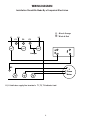
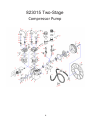
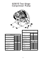
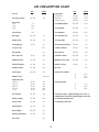
Compressor Operating and
Maintenance Manual
TWO STAGE 15 HP PUMP
SA315240H346
MODEL: _________________________
SERIAL #_________________________
SAFETY INSTRUCTIONS
When using air compressors and compressed air
accessories, basic safety rules and precautions should
always be followed including the following:
1. Read all instructions fully.
2. Wiring, starters, breakers and other related electrical equipment should conform to
electrical codes.
3. Shut off main power and release all pressure from the unit and set pressure regulator to zero pressure before removing or adding parts or attachments and before cleaning compressor.
4. Do not operate any compressor with damaged
wiring. Do not operate after the compressor or
air handling parts have been dropped, damaged,
or shows signs of deterioration, weakness or
leakage. Do not use them if any deficiency is found. Withdraw from service and repair or
discard such parts.
5. Regularly inspect hose and load handling
fittings for signs of damage, deterioration, weakness or leakage. Do not use them if
deficiency is found. Withdraw from service and repair or discard such parts.
6. Never use air pressurized accessories or parts in the air system not suitable for the maximum air pressure involved. This is dangerous. Be sure maximum pressure specified by the manu-
facturer is well above the working pressure of your compressor.
7. Keep clear of compressor. It will become
extremely hot. Moving parts should be avoided. Do not operate without belt guard.
8. Keep pressure relief devices free from paint or other accumulation.
9. Drain tank daily to prevent rust formation in the tank.
10. Never reset pressure switch or safety valves.
11. Never store flammable liquids or gases in the vicinity of the compressor or compressor
starting equipment.
12. SHUTOFF VALVES ARE NOT TO BE INSTALLED
IN THE DISCHARGE LINE BETWEEN THE
COMPRESSOR AND THE RECEIVER UNLESS A
SAFETY VALVE, WITH ADEQUATE FLOW
CAPACITY AND PRESSURE SETTING, IS
LOCATED BETWEEN SHUTOFF VALVE AND THE
COMPRESSOR.
13. When compressor is used for spraying:
Do not spray in vicinity of open flame or other surfaces of ignition.
14. Do not smoke when spraying paint, insecticides, or other toxic or flammable substances.
15. To avoid spontaneous combustion, discard waste
rags into approved metal waste cans.
16. Do not spray in confined spaces.
17. Use face mask when spraying.
18. Always direct paint or sprayed material away from compressor and locate compressor to
minimize paint overspray accumulation on
compressor or sprayer parts.
19. When using cleaning solvent, follow the
instructions provided by the solvent manufacturer.
INSTALLATION AND OPERATING INSTRUCTIONS
UNPACKING INSTRUCTIONS
The two stage compressor was inspected at the factory and packaged to protect against shipping damage. When you unpack your unit, inspect for damaged
or missing parts. If there is any damaged or missing
part, the transportation company’s agent should make
a notation to the effect on the Bill of Lading. Claims,
should be settled directly with
the transportation company.
DIRECTION OF ROTATION
As the compressor starts, check the rotation of the
units, Standard rotation is clockwise, viewing the
compressor from the side of the sight glass. A rotation arrow, is placed on the flywheel at the factory.
Should the rotation be incorrect, disengage the power
and correct the motor wiring.
WARNING: AFTER THE COMPRESSOR IS STARTED,
IT WILL OPERATE AUTOMATICALLY.
START-STOP (PRESSURE SWITCH CONTROL)
When the air pressure in the receiver reaches the
preset high pressure level the pressure switch opens,
electrically stopping the compressor driver motor. As
the air is used from the receiver the pressure drops
allowing the pressure switch to close at the preset
low pressure level, restarting the driver motor.
INSTALLATION
The compressor must be placed in a clean and wellventilated room. Compressor should be located
at least 12 to 18 inches away from a wall or other
obstruction that will impede the flow of air through
the fan-bladed flywheel. Rotation of the fly-wheel
must be in the direction of the arrow cast into the
flywheel.
The compressor should be as near a possible to air
outlets to avoid long pipe lines. Do not place compressor where heat is excessive. Provide adequate
fresh air and exhaust ventilation from area in which
the compressor is located.
Place compressor on a firm, level floor. Permanent
installations should be bolted to the floor. Bolting
holes are provided in the base feet. Shim compressor
level before bolting down to floor. Avoid putting stress
on a foot by pulling it down to floor. This may cause
abnormal vibration. Remove wood shipping skid
before installation.
LUBRICATION OF COMPRESSOR
This compressor was shipped without oil. Before operating, fill crankcase with oil to level on oil sight gauge. Do
not over fill. Oil recommended: Premium Grade SchraderAir 826020 - 30WT Non-Detergent. Change oil every
three (3) months or 500 hours. After initial start up change oil after first two weeks of operation. If oil turns
milky replace oil and move unit to less humid conditions.
PRESSURE SWITCH ADJUSTMENT & UNLOADER
The pressure switch has a range adjustment and a differential adjustment. See instructions located under pressure switch cover. The Cut-Out (Compressor Shutdown) is the pressure at which the contacts open, and the CutIn (Compressor Restart) is the pressure at which the switch contacts close.
Pressure switch controls the opening and closing of the contacts in the magnetic starter. Do not wire electric
motor directly to pressure switch.
The pressure switch has an unloader or bleeder valve which unloads compression from the compressor for a
loadless start-up. Each time the compressor cuts off air should be released to atmosphere from the bleeder
valve. Air will disperse from this valve for only a few seconds, then stop. (Check Daily)
AIR INLET FILTER/SILENCER
It is very important that the air inlet filter/silencer be kept clean at all times. A dirty inlet filter reduces the
capacity of the compressor.
3
WIRING DIAGRAM
Installation Should Be Made By a Competent Electrician
C2
L3
C3
Jumper
K2
T
1
T
2
Line
C1
L2
Motor
L1
C1 - Blue & Orange
C2 C3 - Black & Red
3
Phase
Motor
T
3
L2, L3 indicates supply line terminals. T1, T2, T3 indicates load.
4
MAINTENANCE
DAILY
•
•
•
•
MONTHLY
Check compressor visually.
Check oil level and add oil as required.
Drain moisture from system piping.
Drain moisture from tank daily to prevent rust.
•
•
Check operation of high pressure safety valve
by pulling ring.
Check flywheel and motor pulley for tightness.
QUARTERLY
WEEKLY
•
•
Turn power off and drain moisture from tank
by opening drain cock in bottom of tank.
• Remove and clean intake air filters. Disassemble and wash element in detergent solution. Do not oil.
• Check V-belts for tightness. Belt tension should be adjusted to allow approximately 1/4 - 1/2 inch deflection with normal thumb pressure.
• Turn power off and clean dust and foreign material from cylinder head, motor, fan blade, air lines, intercooler and tank.
•
Every 90 days also check entire system for air leakage around fittings, etc. using a soap solu-
tion. Tighten nuts and cap screws as required.
Every 90 days or 1,000 operating hours, whichever comes first, change crankcase oil. Oil recommended: Premium Grade SchraderAir
826020 - 30WT Non-Detergent. Change oil more
frequently, if compressor is located in very dirty environment.
" Oil capacity 6 quarts "
MAINTENANCE SCHEDULE - CHECK CHART
PROCEDURE
DAILY
Check Oil Level. Caution! Do not overfill.
X
Give Compressor overall visual check
X
Drain moisture accumulation from
the air receiver
X
WEEKLY
Check the air distribution system for air leaks
X
Clean cooling surfaces of compressor,
intercooler and aftercooler
X
MONTHLY
Operate safety valves (pressure relief valve)
X
Replace or clean intake filter element
X
Inspect oil for contamination and change if
necessary
X
Check belts for correct tension and alignment
X
Check pulley clamp bolts and set screws for
tightness
X
YEARLY
XX
Inspect valve assemblies
Inspect cushion chamber, if so equipped,
and discharge line for excessive carbon
accumulations
X
Inspect pressure switch diaphragm and
contact points
X
Service electric motor
‡
Drain Tank
X
X = Check more often if extremely dirty condition exists.
‡ = Per manufacturer’s recommendations
5
‡
XX = Every 6 months
‡
‡
TROUBLESHOOTING
PROBLEM
POSSIBLE CAUSE
CORRECTIVE ACTION
1. Compressor will not operate.
1. No electrical power.
2. Pressure switch not making contact
1. Turn on power.
2. See pressure switch adjustment.
2. Excessive noise in operation
1. Loose pulley, flywheel, belt, beltguard, 1. Tighten.
cooler, clamps or accessories.
2. Check for possible damage to
2. Lack of oil in crankcase.
bearings, replenish oil.
3. Remove the compressor cylinder
3. Piston hitting the valve plate.
head and inspect for foreign
matter on top of the piston.
Add a new gasket and reassemble
the head.
4. Compressor floor mounting loose.
4. Tighten.
5. Repair or replace.
5. Defective crankcase.
6. Adjust and shim properly.
6. Excessive crankshaft end play.
3. Knock - same cycle as R.P.M.
1. Main bearings.
2. Connecting rod bearing.
1. Replace bearings.
2. TIghten.
4. Knock occurs while
compressor is loading.
1. Connecting rod bearings.
2. Wrist pins, wrist pin bearings.
1. Replace rod.
2. Replace complete piston
assembly.
5. Milky oil in oil reservoir.
1. Water entering oil reservoir due
to compressor operating in high
humidity environment.
1. Pipe air intake to less humid air\
source.
6. Excessive oil consumption.
1.
2.
3.
4.
Restricted air intake.
Oil leaks.
Worn piston rings.
Wrong oil viscosity.
5. Compressor titled too much.
6. Scored cylinder.
7. Oil in discharge air.
1. Compressor air intake restricted.
2. Worn piston rings.
3. Excessive oil in compressor.
4. Wrong oil viscosity.
5. Piston rings installed up-side down.
8. Compressor vibrates.
Clean or replace air filter.
Tighten bolts or replace gasket.
Replace piston rings.
Drain oil, refill with oil or proper
viscosity. See Lubrication Section.
5. Level compressor.
6. Replace cylinder.
1.
2.
3.
4.
1. Mounting bolts loose.
2. Compressor not properly mounted.
3. Pulley and flywheel misaligned.
4. Belts loose.
5. Bent crankshaft.
6
1. Clean air filter element and check
for other restrictions in the intake
system.
2. Replace rings.
3. Drain down to full mark on sight
gauge.
4. Check viscosity. See Lubrication
Section.
5. Install ring in proper position.
1. Tighten.
2. Level compressor so that all feet
touch the floor before tightening
down.
3. Realign.
4. Tighten belts. See Maintenance
Section.
5. Replace crankshaft.
TROUBLESHOOTING (continued)
PROBLEM
POSSIBLE CAUSE
CORRECTIVE ACTION
9. Air blowing our of inlet
1. Broken first stage inlet valve.
1. Replace valve assembly.
10. Insufficient pressure at point of use.
1. Leaks or restriction.
1. Check for leaks, restriction, or
piping. Repair problem.
2. Clean or replace air filter
element.
3. Tighten belts. See Maintenance
Section.
4. Replace with larger hose.
5. Limit air requirement to
compressor capacity.
2. Restricted air intake.
3. Slipping belts.
4. Service hose too small.
5. Excessive air requirement.
11. Receiver does not hold pressure
when compressor is unloaded.
1. Faulty check valve.
1. Bleed Tank! Disassemble check
valve assembly, clean or
replace faulty parts. DANGER DO NOT DISASSEMBLE CHECK
VALVE WITH AIR IN TANK.
NOTE - CHECK VALVE IS
ALWAYS THE FIRST VALVE IN
THE LINE LEADING FROM THE
TANK TO THE COMPRESSOR.
12. Excessive belt wear.
1. Pulley out of alignment.
1. Realign motor pulley with
compressor flywheel.
2. Adjust tension. See Maintenance
Section.
3. Adjust tension. See Maintenance
Section.
4. Check for worn crankshaft,
keyway or pulley bore, resulting
from running with loose pulleys.
Check for bent crankshaft.
5. File smooth.
2. Belts too tight.
3. Belts too loose.
4. Pulley or flywheel wobble.
5. Nick in belt grove of pulley or
flywheel.
13. Excessive discharge air
temperature.
1. Dirty cooling surfaces.
2. Poor ventilation.
3. Blown head gasket.
4. Restricted air intake
5. Worn valves.
14. Receiver pressure builds
up slowly.
1. Dirty air filter.
2. Blown cylinder head gasket.
3. Worn or broken low pressure
intake or discharge valves.
4. Air leaks.
5. Loose belts.
6. Speed too slow.
7
1. Clean cooling surfaces of cylinder,
intercooler and discharge tube.
2. Improve ventilation or relocate
compressor. See Installation.
3. Replace head gasket.
4. Clean or replace air filter element.
5. Repair or replace valves.
1. Clean or replace filter element.
2. Install new gasket.
3. Install new head gasket.
4. Tighten joints.
5. Tighten belts. See Maintenance
Section.
6. Check speed.
823015 Two-Stage
Compressor Pump
8
823015TX - PUMP PARTS
ITEM
QTY
ITEM
PART #
DESCRIPTION
1
PART # DESCRIPTION
430001
Crankcase GS43
1
44
431030-1
HP Wrist Pin - Piston GS43
1
2
430002
Cap-Rear GS43
1
45
431031
Snap Ring - Internal 30
4
3
430003
Crankshaft GS43
1
45-1
431031-1
Snap Ring - Internal 28
2
4
430004
Balance GS43
2
46
431032
Piston Ring Set GS43
2
5
430005
Cap - Front GS43
1
47
431032-1
HP Piston Ring Set GS43
1
6
430006
Flywheel GS43
1
48
431033
Gasket - Cylincer to Crankcase GS43
7
430007
Fan GS43
1
49
431034
Capscrew - Hex M12X335
QTY
3 (*a)
24
8
430008
Cylinder GS43
2
50
431035
Gasket - Cylinder Head GS43
2 (*a)
9
430009
Head GS43
2
51
431035-1
Gasket - Cylinder Head GS33
1 (*a)
1
52
431036
Valve Copper Gasket GS43
4
10
430008-1 HP Cylinder G43
11
430009-1 Head GS43
1
53
431037
Disch Valve GS43
2
12
431001
Capscrew - HEX M10X30
26
54
431038
"O" Ring - Hold Down Cover GS43
4
13
431002
Lock Washer Φ 10
35
55
431039
Hold Down Cover - Disch GS43
2
14
431003
Breather - Crankcase GS43
1
56
431040
Inlet Valve GS43
2
15
431005
Oil Baffle Plate GS43
1
57
431041
Unloader Piston GS43
2
16
431005
Gasket - Rear Cap GS43
1 (*a)
58
431042
"O" Ring - Unloader Piston GS43
2
17
431006
Oil Sight Glass GS43
1
59
431043
Hold Down Cover - Inlet GS43
2
18
431007
Oil Drain Plug GS22
1
60
431044
Capscrew - Hex M10X80
6
19
431008
Bearing - Front 32210
1
61
431036-1
Valve Copper Gasket GS33
2
20
431009
Capscrew - HEX M16X20
2
62
431037-1
HP Disch Valve G43
1
21
431010
Lock Washer Φ 16
2
63
431038-1
"O" Ring - Hold Down cover GS33
2
22
431011
Bearing Rear 30310
23
431012
Gasket - Front Cap GS43
24
431013
25
26
1
64
431039-1
Hold-Down Cover-Disch GS33
1
1 (*a)
65
431040-1
HP Inlet Valve G43
1
Shim-Brg Adjustment GS43
1
66
431041-1
Unloader Piston G33
1
431014
Seal - Shaft GS43
1
67
431042-1
"O" Ring-Unloader Pisotn GS33
1
431015
Spacer - Flywheel GS43
1
68
431043-1
Hold Down Cover - Inlet GS331
1
27
431016
Key - Flywheel
1
69
431045
Capscrew - Hex M8X25
8
28
431017
Capscrew - Hex M12X40
1
70
431046
Copper Elbow GS43
1
29
431018
Lock Washer Φ 12
25
71
431047
Copper Nut GS12
5
30
431019
Capscrew - Hex M8X30
6
72
431048
Copper Seal Ring GS43
5
31
431020
Lock Washer Φ 8
17
73
431049
Aluminum Tube Φ 6 GS43
2
32
431021
Filter - Inlet Assembley GS43
2
74
431050
Tee-Male Tube GS12
2
33
34
35
431022
431023
Filter - Replacement Element GS43
2
75
431051
Nut- Compression GS43
1
Oil - Plug GS43
1
76
431052
Elbow GS43
3
1
77
431053
Tee GS43
1
36
431024-1 HP Connecting Rod GS43
431024
Connecting Rod GS43
2
78
431054
Intercooler Tube GS43
1
37
431025
Insert Half GS43
3
79
431055
Intercooler Tube GS43
1
38
431026
Nut M8
3
80
431056
Capscrew-Hex M10X20
1
39
431027
Straight Dipper - Oil GS43
1
81
431057
Cooler Line Strap G43
1
40
431028
Oblique Dipper - Oil GS43
2
431029
Piston GS43
2
*a
430000-1
COMPLETE GASKET KIT GS43
1
41
42
43
431029-1 HP Piston GS43
431030
Wrist Pin - Piston GS43
1
2
#63 VITON HIGH TEMP O-RING = 55 X 3 PART# 93602-870055 need 2
#54 O-Ring - 93602-810065 - need - 4
9
82-P7575 - Check Valve
10
DAFENG LIDA COMPRESSED AIR SYSTEMS CO.,LTD
DAFENG
823015 Two-Stage
(SINO-USA)
Compressor Pump
LIDA COMPRESSED AIR SYSTEMS CO.,LTD
823015 Technical Data
HP
Motor
Dimensions
A
B
C
Dimensions
inch
mm
inch
mm
inch
mm
inch
mm
inch
mm
inch
mm
lb
kg
inch
L(Shape) mm
W(Shape) inch
mm
H(Shape)
inch
Weight
mm
inch
(Shape)
mm
inch
(Shape) MODEL G43
mm Two
inch
(Shape)
mm
15.59
396
8.98
228
6.85
174
15.59
31.10
396790
22.05
8.98
560
22825.59
650
6.85
335.16
174152
31.10
790
22.05
560
Stage
25.59
650
KW Technical
11
823015
Data
Air Delivered
Pressure
Motor
Rpm
Cylinders
Air
Bore
15
ACFM
m3/min
PSI
Bar
43.1
1.22
172 HP
12
KW
120X2, 100X1
ACFM
4.72(3.94)
inch
m3/min
Delivered
Stroke
Pressure
Flywheel
Rpm dia.
Groove Type
860
mm
inch
mm
inch
mm
Cylinders
120(100)
3.15 PSI
80 Bar
13.78
350
B
Bore
Air Compressor
Stroke Pump
11
15
Flywheel dia.
11
43.1
1.22
172
12
860
120X2, 100X1
inch
mm
inch
mm
inch
mm
4.72(3.94)
120(100)
3.15
80
13.78
350
AIR CONSUMPTION CHART
Air file
PSI
4.0*
Air filter cleaner70-100
Air motors
1 HP
2 HP
3 HP
PSI
SCFM
Spray gun
Production
Touchup
Undercoating
3.6*
90-10016.0*
90-1008.0*
90-10019.0*
Tire bead breaker125-150
7.0
13.0
19.0
SCFM
12.0*
Tire changer 125-1501.0
Air polisher16.0
Tire hammer
Blow gun
Tire inflation line125-150
90-1002.4
90-10012.0
1.4
Brake tester 70-1003.6
Tire spreader 125-1501.0
Caulking gun 10-702.2
Transmission flusher70-100
Circular saw17.0
Carbon remover70-100 3.0*
Die grinder6.0
Burring tool 90-1005.0*
Drill, 3/8 inch 70-904.0*
Vacuum cleaner
Engine cleaner90-100 5.0
Hydraulic floor jack125-150
Fender hammer
70-1009.0*
Radiator tester
Filing machine
90-1005.0*
Air saw
Grease gun
120-1506.0*
Vertical air sanders
5”12.0
7”16.0
9”18.0
Vertical grinder
3”6.0
4”12.0
7”24.0
Hydraulic lift6.0-12.0*
Impact wrench
3/8 inch
1/2 inch
5/8 inch
3/4 inch
1 inch
70-90
70-90
70-90
70-90
70-90
Air hammer
90-1007.0*
3.0*
4.0*
5.0*
8.0*
12.0*
3.0
125-1506.0
6.0
90-1001.1
6.0
Orbital sander 70-10012.0*
Consult the spec. supplied with your air tool or
equipment for the exact operating pressure and
air volume requirements.
Panel cutter 70-1004.0
*Continuous Run Tools
Nail hammer 90-1004.0
Rim stripper
125-150
Spark plug cleaner90-100
5.0
5.0
Air scaler5.0
12
Schrader International Inc.
Warranty Statement
For (1) one year from the date of purchase, Schrader International Inc. will replace or repair for the original purchaser
free of charge, any part or parts found upon examination
by manufacturer/any Authorized Service Center to be
defective in material or workmanship
or both. This warranty shall not be effective unless the
warranty registration certificate is completely filled out
and returned to Schrader International Inc. within thirty
(30) days from the delivery of the equipment to the original
end-user.
All transportation charges for parts submitted for replacement under this warranty must be borne by the purchaser.
There is no other express warranty. Implied warranties,
including those of merchantability and fitness for a
particular purpose are limited to one year from the date
of purchase and to the extent permitted by law, any and
all implied warranties are excluded. This is the exclusive
remedy, and liability for consequential damages under any
and all warranties are excluded to the extent exclusion is
permitted by law.
All claims pertaining to the merchandise in this schedule
must be filed with Schrader International Inc. within 12
months of the invoice date, and a registration card is on
file with Schrader, or they will not be honored. Prices,
discount, and terms are subject to change without notice
or as stipulated in specific product quotations. All agreements are contingent upon strikes, accidents, and other
causes beyond our control. All shipments are carefully
inspected and counted before leaving the factory. Please
inspect carefully any receipt of merchandise, noting any
discrepancy or damage on the carrier’s freight bill at time
of delivery. Discrepancies or damage, including hidden or
obvious that occurred in transit are the carrier’s responsibility and related claims should be made by the customer
directly with the carrier.
13
To locate the closest Authorized Service Center for service
assistance, resolution of a service problem or for product
information and operation, call or write to:
Schrader International Inc.
205 Frazier Road
Altavista, VA 24517
Email: [email protected]
1.800.288.1804
Tech Service, ext. 1577
What is not covered under this warranty:
• Electric motors or gasoline engines are covered by the
Original Manufacturer’s Warranty and should be returned
(by the customer) to their authorized service center for
service.
• Consumer compressors used in commercial, industrial or
rental purposes will be covered by warranty for (90)
ninety days from date of purchase only.
• Any failure that results from an accident, purchaser’s
abuse, neglect or failure to operate products in
accordance with instructions provided in the owner’s
manual(s) supplied with compressor.
• Pump or valve failure caused by rain, excessive humidity,
corrosive environments or other contaminants.
• Cosmetic defects that do not interfere with the
compressor’s functionality.
• Damage due to incorrect voltage or improper wiring.
• Pump wear or valve damage caused by any oil
contamination or by failure to follow proper oil
maintenance guidelines.
• This warranty is invalid if the factory-applied serial
number has been altered or removed from the product,
or an electric compressor has been used in conjunction
with a generator.
• Freight damage
CUSTOMER SERVICE • SALES
1-800-327-1335
TECHNICAL SERVICE • PARTS
1-800-345-0578
Schrader International, Inc.
P.O. Box 668 • 205 Frazier Road
Altavista, Virginia 24517
823015 Manual 011112