1
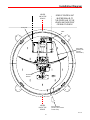
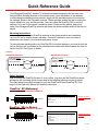
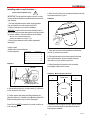
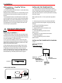
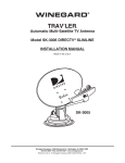
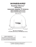
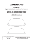
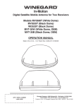
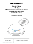
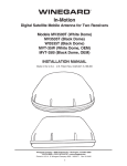
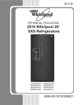
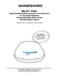
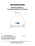
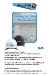
WINEGARD® RoadTrip® Digital Satellite Mobile TV Antenna for Two Receivers RoadTrip® SD - Stationary Satellite TV Antenna RoadTrip® SDi - In-Motion Satellite TV Antenna INSTALLATION MANUAL Winegard Company • 3000 Kirkwood St. • Burlington, IA 52601-2000 319/754-0600 • FAX 319/754-0787 • www.winegard.com Printed in U.S.A. © Winegard Company, 2008 2452165 Rev3 8/10 1 Parts Included • Tools Needed • How to Unpack The Winegard RoadTrip® antenna is designed specifically for use with motorized recreational vehicles. Winegard recommends using a qualified installer familiar with RV structures and wiring to ensure proper installation and to prevent damage to the RV or satellite dish. PARTS INCLUDED: 1 Radome 1 Cable entry plate All required screws, washers, bolts, and nylocks 1 base with electronics, dish, dual LNBF, mounting feet 4’ Gray Coax Cable (OEM Model) 4’ White Coax Cable (OEM Model) 4’ Power Cable (OEM Model) TOOLS NEEDED FOR UNPACKING & INSTALLATION: Level Drill w/3/4” bit 1-1/4” hole saw (if mounting switch in wall) Phillips screw driver #2 3/8” Open end wrench 7/16” Open end wrench Sealant (consult RV manufacturer for proper type for your roof material) UNPACKING THE UNIT 1. Open box and remove packing material. LIFT UNIT STRAIGHT UP OUT OF CARTON! ! If using knife to open carton, BE CAREFUL. Do not cut the dome on the unit. 2. Lift dome out of box vertically. Then lift unit out of box vertically. Do not turn box and “roll” out, or turn upside down to remove. USE 2 PEOPLE when removing the unit from the carton. ! DO NOT PAINT DOME! Painting dome will cause signal degradation and will void your warranty. 2 Rev. 5/06 Installation Diagram CENTER LINE OF THE VEHICLE SIDES OF CONTROL UNIT MUST BE PARALLEL TO THE CENTER LINE OF THE VEHICLE AND FACE FRONT OR REAR OF VEHICLE. Control Unit LNBF GPS CABLE (RoadTrip SDi In-Motion models ONLY) ELEVATION MOTOR CENTER LINE OF THE VEHICLE GPS ANTENNA (RoadTrip SDi In-Motion models ONLY) Rev. 5/06 3 Quick Reference Guide Your Winegard RoadTrip® satellite TV antenna has been designed to be the most userfriendly Mobile Satellite Antenna on the market today. Upon installation of the antenna, or after changing satellite service provider, simply set the switches inside of the dome to the settings shown in the Operation manual. These switches enable the dish to locate the proper satellite for your service provider. They also allow the RoadTrip SDi (in-motion) antenna, to be set for the proper installation option. Simply set the switch, and you’re done! Your Winegard RoadTrip antenna will locate the proper satellite with just the flip of a switch. Mounting Instructions It is essential to mount your RoadTrip antenna in the proper position and orientation on your RV roof to ensure proper operation. Choose a location on your roof clear of obstruction and close to your receiver and power source. To ensure proper tracking with your RoadTrip SDi (in-motion) antenna, you must mount the unit so that the unit is centered on the centerline and cables exit either towards the front or back of the RV. See Figure 1c below. Figure 1c MOUNTING OPTION A MOUNTING OPTION B ALIGN FEET EXACTLY SQUARE ON Center line of vehicle AS SHOWN BACK OF VEHICLE CABLE EXIT REAR BACK OF VEHICLE MV-3500 RoadTrip FRONT OF VEHICLE FRONT OF VEHICLE ALIGN FEET EXACTLY SQUARE ON Center line of vehicle AS SHOWN MV-3500 RoadTrip CABLE EXIT FRONT Switch Settings After mounting the RoadTrip System to your rooftop, you must set the RoadTrip’s switch settings for the mounting option chosen and for the satellite television service provider. The chart below lists switch settings for both the RoadTrip SD and RoadTrip SDi. See page 3 of the Operation Manual for detailed instructions. RoadTrip® SD (Stationary) FACTORY PRESET FOR DIRECTV SHOWN 0 = up 1 2 3 4 5 0 0 0 0 0 6 0 7 (#1 represents Switch DOWN; #0 represents Switch up) 8 0 1 1 = down Sat. Rcvr. Mt. Option Switch Set Position 1 2 3 DIRECTV A (FACTORY PRESET) DISH NETWORK RoadTrip SDi (In-Motion) ® A 0 0 0 4 0 5 0 6 0 7 0 8 1 0 0 0 1 0 0 1 1 0= up SWITCH SETTINGS OPTIONS 1= down FACTORY PRESET FOR DIRECTV SHOWN 1 0 = up 0 2 0 3 0 4 0 5 0 6 0 7 0 (#1 represents Switch DOWN; #0 represents Switch up) 8 1 1 = down Sat. Rcvr. Mt. Option DIRECTV (FACTORY PRESET) DIRECTV DISH NETWORK DISH NETWORK 4 A B A B Switch Set Position 1 2 3 0 0 0 4 0 1 0 1 0 0 0 0 0 0 0 1 1 0= up 5 0 6 0 7 0 8 1 0 0 0 0 0 0 0 1 1 1 1 1 1= down SWITCH SETTINGS OPTIONS Rev. 5/06 Installation Installing unit on roof of vehicle — Install in DRY conditions only! ! 6. Place the unit on the roof in its permanent location and mark around each base foot, Figure 4. IMPORTANT! Do not install this system in the rain, or under any wet conditions. Moisture may affect electronics and void your warranty! FIGURE 4 1. For best performance and to reduce signal acquisition time, park vehicle on a level surface; level the RV. 2. Select a level spot on your roof for installation. WARNING: Level the base front to back and side to side. If base is not level the antenna may require more time to locate the correct satellite or may not locate the correct satellite. • Be sure no roof-mounted equipment is blocking the satellite “line of sight”, Fig. 3. 3. Ensure proper distance to other rooftop equipment is maintained. Using this chart, determine the minimum distances to other equipment. Obstruction Ht. 7. Clean roof area where the base feet will be attached to the roof. Do not erase your marks! Unit Clearance 8”..................................................2” 8. Put approved sealant in the areas marked for the base feet. Place base feet on top of the sealant and screw down with the (3) #10 screws for each foot. 10”................................................8” 12”..............................................13” 15”..............................................22” 9. After all base feet are secured to roof, put sealant around edge of feet and over screws. FIGURE 3 ION UNIT BASE OBSTRUC T FIGURE 5, Mounting Option A shown Front of Vehicle Center Line A’ 4. After selecting location for unit (see number 2), put the unit on the centerline of the vehicle. B’ RoadTrip 5. Position base so that cables exit either toward the rear (Mounting Option A) or toward the front (Mounting Option B InMotion mounting option only) of vehicle. See page 4. Control Unit box MUST be parallel to the center line of the vehicle. See page 3. The distance from the edge of the roof to the rear corner of the foot should be equal on both sides of the dish to ensure proper installation. 5 Rev. 5/06 Installation GPS installation — RoadTrip® SDi (for in-motion) only INSTALLING THE POWER SWITCH 1. Choose a location to install the RoadTrip power ON/OFF switch. Remember when selecting a location that you will need to run the +12VDC power cable from the RoadTrip antenna to the switch. Be sure the switch is in the OFF position before continuing. See Figure 7 page 6. 10. The GPS antenna is pre-wired and has a 1 meter cable running through one of the connectors. Determine location for GPS antenna. It is recommended you place the GPS antenna 3 feet from dome and away from any other obstruction. Wall or panel mount: Drill 1-1/4” hole, pull wires through wall or panel. The recommended location for the GPS antenna is based on having a level location and a clear view of the sky for the best satellite signal acquisition. Do not secure GPS antenna to roof at this time. 2. Connect the ground wire from the vehicle and the BLACK ground wire from the antenna together, using large yellow flag connector. 3. Connect the YELLOW flag connector to the silver spade on the switch. 4. Connect the RED wire from the antenna to the small RED flag connector. 5. Connect small RED flag connector to center spade on switch. 6. Connect the +12 V power wire from the vehicle to a small RED flag connector. 7. Connect small RED flag connect to isolated spade on switch. IMPORTANT! The GPS must be located minimum of 3 feet away from obstructions on roof of vehicle. Antenna must have a clear view of the sky for proper operation. ! NICKS OR CUTS IN WIRING JACKET MAY CAUSE WATER TO LEAK INTO VEHICLE. Cable entry installation — 1. Decide the best location for the power and coax cables to enter the vehicle, and the location of the power switch and receiver. Drill a 1/2” hole in the roof, push wires inside. Make proper connections. You must have filtered +12 VDC power source. 2. For a two receiver installation, connect a second coax cable (not provided) to the ground block-type coax connector. Route this cable through the empty Heyco connector on base and run cable along roof to second receiver location. 3. Place cable-entry plate over hole and cables. Screw in place. Seal plate and screw holes with approved sealant (not included). 4. Depending on the length of the cable on the roof, you may need to use cable clamps or wire ties (not provided) between the unit and your cable-entry plate. Clamping the cable every 12”-16” should eliminate any unnecessary cable movement, Figure 6. INSTALLING THE POWER SWITCH DIAGRAM FIGURE 7 ON/OFF ROCKER SWITCH WITH LIGHT (Shown in OFF position.) steps 2 & 3 Two GROUND wires 1 frOm vehicle 1 Black wire from SATELLITE DISH FIGURE 6 STEPS 6 &7 +12 v FROM VEHICLE sTEPS 4 & 5 RED POWER WIRE FROM DISH COAX CABLE ROUTING PRIMARY RECEIVER MV-3500 RoadTrip SECONDARY RECEIVER 6 Rev. 5/06 Installation • Wiring • Specifications Connecting the receiver — ! To order receivers or programming please call the Winegard receiver hotline: 1-(866) 609-9374. Your RoadTrip® antenna has now been successfully installed. Proceed to the Operation Manual for RoadTrip antenna setup and for Operation Instructions. Connecting one receiver 1. Connect the coax cable from the antenna to the “SATELLITE IN” on the receiver. 2. See page 5 of Operation Manual for receiver set-up. Connecting two receivers 1. Connect the coax cable coming from the antenna to the “SATELLITE IN” input on the primary receiver. The primary receiver is the receiver used most often and will toggle between satellites. 2. Connect the secondary coax cable coming from the antenna to the “SATELLITE IN” input on the secondary receiver. NOTE: Secondary receiver will not toggle. 3. See page 5 of Operation Manual for receiver set-up. Features and specifications • One button operation. • Dual receiver capable. • Depending on receiver type, you can access satellites 119°, 110°, or 101°. • No user input required. • Elevation range 20° to 60°; azimuth +360° (0-720°) • Dome UV protected. • Compact size — 32” diameter, 12-1/2” height Shipping size - 37-1/4” x 34” x 14-3/4” Unit Weight - 35 lbs. Shipping Weight - 53 lbs. • Operating temperature -13°F to +140°F • Specifications for max amperage 5.0A • Specifications for unit operatating voltage. -10.5 - 13.8V • Specifications for supply voltage. 12 - 13.8V 7 Rev. 6/10 WINEGARD MOBILE PRODUCTS LIMITED WARRANTY (2 YEARS PARTS; 1 YEAR LABOR) Winegard Company warrants this product against defects in materials or workmanship for a period of two (2) years from the date of original purchase. During year one (1) of such warranty, Winegard Company will also pay authorized labor costs to an authorized Winegard dealer to repair or replace defective products. No warranty claim will be honored unless at the time the claim is made, Customer presents proof of purchase to an authorized Winegard dealer (to locate the nearest authorized Winegard dealer, contact Winegard Company, 3000 Kirkwood Street, Burlington, Iowa 52601, Telephone 319-754-0600 or visit www.winegard.com). Customer must provide proof of purchase with a dated sales receipt for the Winegard product to verify the product is under warranty. If the date of purchase cannot be verified, the warranty period shall be considered to begin thirty (30) days after the date of manufacture. If a defect in material or workmanship is discovered, Customer may take the product to an authorized Winegard dealer for service. Customer must provide proof of purchase to verify the product is under warranty. If the product is brought to an authorized Winegard dealer for service prior to expiration of year one (1) of the warranty period and a defect in material or workmanship is verified by Winegard Technical Services, Winegard Company will cover the Winegard dealer’s labor charges for warranty service. The Winegard dealer must contact Winegard Technical Services in advance for pre-approval of the service. Approval of the service is at the sole discretion of Winegard Company. Alternatively, Customer may ship the product prepaid to Winegard Technical Services (located at 3000 Kirkwood Street, Burlington, Iowa 52601, Telephone 319-7540600). Customer must return the product along with a brief description of the problem and provide Winegard Technical Services with Customer’s name, address, and phone number. Customer must also provide proof of purchase to verify the product is under warranty. If the product is returned before the expiration of the warranty period, Winegard Company will (at its option) either repair or replace the product. This Limited Warranty does not apply if the product has been damaged, deteriorates, malfunctions or fails from: improper installation, misuse, abuse, neglect, accident, tampering, modification of the product as originally manufactured by Winegard in any manner whatsoever, removing or defacing any serial number, usage not in accordance with product instructions or acts of nature such as damage caused by wind, lightning, ice or corrosive environments such as salt spray and acid rain. This Limited Warranty also does not apply if the product becomes unable to perform its’ intended function in any way as a result of the television signal provider making any changes in technology or service. RETURN AUTHORIZATION POLICY A Return Material Authorization (RMA) is required prior to returning any product to Winegard Company or Winegard Warranty Services under this warranty policy. Please call our Technical Services Department at (800) 788-4417 or send an e-mail to [email protected] to obtain the RMA number. Please furnish the date of purchase when requesting an RMA number. Enclose the product in a prepaid package and write the RMA number in large, clear letters on the outside of the package. To avoid confusion or misunderstanding, a shipment(s) without an RMA number(s) or an unauthorized return(s) will be refused and returned to Customer freight collect. WINEGARD COMPANY DOES NOT ASSUME ANY LIABILITIES FOR ANY OTHER WARRANTIES, EXPRESS OR IMPLIED, MADE BY ANY OTHER PERSON. ALL OTHER WARRANTIES WHETHER EXPRESS, IMPLIED OR STATUTORY INCLUDING WARRANTIES OF FITNESS FOR A PARTICULAR PURPOSE AND MERCHANTABILITY ARE LIMITED TO THE TWO YEAR PERIOD OF THIS WARRANTY. In states that do not allow limitations on implied warranties, or the exclusion of limitation of incidental or consequential damages, the above limitations or exclusions do not apply. Some states do not allow limitations on how long an implied warranty lasts, or the exclusion of limitation of incidental or consequential damages, so the above limitations or exclusions may not apply to you. This warranty gives Customer specific legal rights. Customer may also have other rights that may vary from state to state. SATELLITE RECEIVER WARRANTY See manufacturer’s limited warranty policy. Winegard Company • 3000 Kirkwood Street • Burlington, IA 52601 • 319/754-0600 Fax 319/754-0787 • www.winegard.com Printed in U.S.A. © 2008, Winegard8Company 2452165 Rev3 8/10 WS-MOBWARREV2 Rev. 1/10