1
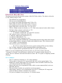
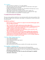
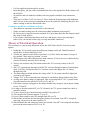
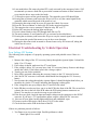
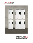
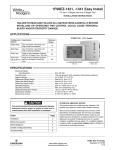
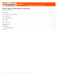
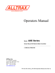
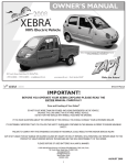
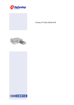
ZAP Xebra Vehicle Electrical
Repair and Troubleshooting
Manual (72V Key)
Last updated on April 26, 2007
Copyright 2007. This document my not be reprinted, published, emailed or posted on the
Internet without the approval of ZAP.
Intended Readers
The purpose of this manual is to provide a mechanic, technician or savvy electric car buff with the
tools to troubleshoot and repair the vehicle. Please be sure you are familiar with the Owner's Manual
before using this guide. This troubleshooting Guide assumes a good knowledge of the Owner's
Manual, the vehicle itself and basic mechanical and electrical skills. Check with ZAP if you are
unsure who to have do the work. ZAP is not responsible for damage to your vehicle or personal
injury for work done by non-qualified personnel.
Version
This document describes the 72V key ignition system which started shipping around March 2007.
Do not use this manual for the 12V key ignition system.
Sections
•
•
•
•
•
•
•
Introduction
12V common
72V common
Common Problems
• Tight Wire Connections
• Fuse Problems
• Connector Problems
Theory of operation
Troubleshooting by Vehicle Operation
• Low Voltage System
• High Voltage System
Troubleshooting by Problem
• No 12 volts
• No DC/DC converter output
• Won't Drive Forward
• Won't Drive in Reverse
• Vehicle Won't Charge
• Test Charger and Batteries
1
Inadequate Charge or Range
Alltrax Motor Controller
Appendix A Figure 1 – 12V electrical schematic
Appendix A Figure 2 – 72V electrical schematic
Appendix A Figure 3 - motor, contactor, motor controller wiring detail
•
•
•
•
•
Electrical Introduction
This document describes the electrical systems of the ZAP Xebra vehicles. The sedan is referred to
as "SD" and the pickup as "PK".
•
•
•
•
•
•
•
•
•
•
•
•
•
•
•
•
•
The schematics are in appendix A.
Wires are given identifying labels.
Low voltage wires prefix the number with "S" (Ex. S1).
High voltage wires prefix the number with "T" (Ex. T1).
Low voltage power wires start with "12V" (Ex. 12VF3).
High voltage power wires start with" 72V" (Ex 72VC).
The low voltage common is referred to as -12V. This is also connected to the vehicle chassis.
The high voltage common is referred to as -72V.
Components are given identifying labels.
• "A" indicates a module (Ex. A1 for DC/DC converter).
"JD" indicates a lower current relay (Ex. JD1).
"J" indicates a high current contactor (Ex. J1).
"L" indicates a light bulb (Ex. L1).
"K" indicates a switch or button (Ex. K24).
There is one complicated multifunction switch mounted on the steering column that controls
the head lights, blinkers, emergency flashers and windshield wipers. This is broken into K11, K1-2 and K1-3 on the schematics.
The electrical system is divided into:
• The 12V low voltage light and accessory system, running off the accessory battery.
The 72V high voltage drive system, operating off the traction battery pack.
The 12V system must be operational before the 72V system can be activated.
Whenever you are troubleshooting an electrical system, it is necessary to know where the
"Common" or "Ground" is located. In these vehicles the 12V system is isolated from the 72V
system. The 12V common is also tied to the metal car frame. The 72V system is completely isolated
(floating).
12V Common
•
•
•
•
•
•
The 12V common is referred to as -12V in the schematics.
The best place to locate the 12V common inside the cab is on the cigarette lighter. You
should get a cigarette lighter plug from an automotive store and solder a black wire to the
-12V side (the outside wall of the connector).
When in the front or rear compartments of the vehicle, use any common (black wire) on a
light bulb connector.
The metal frame is usually not a good place to pick up common.
When using a voltmeter, set to an appropriate scale for 12V (usually the 20V range) and
connect the black voltmeter common to 12V common.
Use your red voltmeter wire to probe the 12V electrical system.
2
72V Common
•
•
•
•
•
•
The 72V common is referred to as -72V in the schematics.
In the SD you can remove the center traction battery cover and connect to the negative
terminal of the battery closest to the dash.
In either the SD or the PK you can remove the center dashboard switch plate (two screws)
and connect to the black wire of the heater switch.
When in the rear of the vehicle, use the B- post on the motor controller A21.
When using a voltmeter, set to an appropriate scale for 72V (usually the 200V range).
Use your red voltmeter wire to probe the 72V electrical system.
Common Electrical Problems
The most common problems include loose wire connections and fuse and connector problems. Since
the Xebra is a simple vehicle, the solution is often simple. It is important to be just like a doctor and
be a good detective.
WARNING and Safety !
•
•
•
•
•
•
Both electrical systems are capable of very high currents (means blinding light, sparks,
fire and welding are possible).
The 72V system is also capable of giving you a serious voltage shock.
When working on the vehicle, all tools and handles should be wrapped in electrical tape
or rubber coated to avoid shorting terminals; that is, never touch the positive to a
negative of any part of the system or any battery.
Positive and negative locations may not be immediately obvious, especially on the
motor controller and the printed circuit card.
Take all standard precautions for electrical systems including removing rings and
watches, wear safety glasses and gloves and proceed cautiously using common sense.
Unless necessary for troubleshooting, make sure the 12V cutoff switch and the 72V
cutoff switch are off. They must always be off whenever you are changing components
(such as the motor controller), fuses or wiring.
Check for Tight Wiring Connections
•
•
•
•
•
•
•
wires on fuse and diode blocks
wires to and between batteries
wires to main traction battery fusible link F9
wires to contactors
wires to motor controller
wires to drive (traction) motor
Make sure the small wires on the motor controller (A21) are tight; crimp as necessary
Fuse problems, solutions and tips
•
•
•
The PK uses standard blade fuses and do not have the following problems.
The SDs originally used wire wound fuses. These fuses can discolor (oxidize) over time
(which causes the resistance to increase). Refer to the waterproofing and reliability guide for
information on replacing these fuses.
If you find such fuses they must be removed and changed to standard
automotive blade fuses.
3
•
•
•
•
Use Zap supplied replacement fuse sockets.
In an emergency you may solder a standard blade fuse to the original fuse holder (remove all
the old wire).
Or purchase and wire blade fuse holders with wire pigtails (available at any automotive
store).
There are six of these "bad" wire fuses, F1-F4 are under the front passenger side dashboard
and F5-F6 are in the rear motor compartment above the contactors. Removing the glove box
makes working on the fuse block much easier.
Connector problems, solutions and tips
•
•
•
•
The connectors sometimes become loose or disconnected.
Simply reconnect making sure the connector latching mechanism seats properly.
Be sure no pins or lugs have become unseated. If so, press them back into the connector until
they snap or catch in place.
If you suspect a bad connection between the wire and the pin, remove pin, uncrimp to
remove wire, cut out bad section, strip, re-crimp and solder connection.
Theory of Electrical Operation
This section gives a step by step description of how the ZAP Xebra vehicle's electrical systems
operate:
1. Enable the 72V electrical system by pulling out (turning on) the red "Main Disconnect"
switch (K21) in front of the driver's seat.
2. Turn the key ignition switch (K26) to position 1 (1st click). It does not matter if you go to
key position 2 since only key position 1 is used.
3. This energizes relay JD4 which activates main contactor J4. On even newer vehicles the key
activates J4 directly and relay JD4 is missing.
4. The key also activates relay JD8 which connects the 12V accessory battery to the 12V
system.
5. Also 72V is placed onto the input of the DC/DC converter through contactor J4 and outputs
about 14.0 VDC which powers the 12V electrical system and charges the 12V battery
through relay JD8.
6. The dash voltmeter should indicate the voltage of the 72 volt system and all the lights and
accessories will operate.
7. Voltage 72VC is also connected from contactor J4 onto battery charger lockout relay JDac.
8. As long as the battery charger is unplugged, JDac is not energized so 72VC is passed to the
forward/neutral/reverse switch K23 over wire T1 and T4.
9. If the battery charger is plugged in, the charger disable relay energizes, removing the voltage
to wire T1 and T4.
10.As long as direction switch K23 is in "N" (Neutral), the 72V goes no further but vehicle is
armed for motion.
11.To drive forward, place the directional switch K23 in position "F".
12.This energizes the forward contactor J3 over T6.
13.Power is then routed to relay JD7 through diode D5 over T8.
14.When either or both the foot and emergency brakes are activated, relay JD7 is energized,
removing coil power to the main contactor J1.
15.When both the foot and emergency brakes are released, relay JD7 is de-energized which puts
power on the main contactor coil J1 over T9.
4
16.Later models have D4 removed so that JD7 is only activated by the emergency brake. ZAP
recommends you remove diode D4 to prevent the constant activation of main contactor J1
every time the driver steps on the foot brake.
17.T9 also places power on the speed controller. The controller green LED should light.
18.Pressing the accelerator pedal causes the 5K pot (A25) to vary the control signal to the
controller which causes the speed of the motor to vary.
19.Placing the direction switch in reverse (R) arms the vehicle for reverse.
20.Press the "Reverse Button" to latch relay JD2 in the energized position.
21.This energizes the reverse contactor J2 and also relay JD1 over T7.
22.Relay JD1 energizes the backup lights and beeper.
23.Power is then routed to relay JD7 through diode D6 over T8.
24.The main contactor J1 and controller A21 are activated as described above.
25.Pressing the accelerator pedal causes the 5K pot to vary the control signal to the controller
which causes the speed of the motor to vary in the reverse direction.
26.Placing the direction switch in neutral or forward causes relay JD2 to turn off, taking the
vehicle out of reverse.
Electrical Troubleshooting by Vehicle Operation
Low Voltage 12V System
The following is the sequence of a properly operating system with probable cause if there is a
failure:
1. Measure the voltage of the 12V accessory battery through the cigarette lighter. It should be
in the 12 to 13V range.
2. If all voltage is absent, make sure fuse F7 is not blown.
3. If the voltage is below 10V you may have a bad 12V accessory battery. Remove and charge
outside the vehicle. If the battery won't take a charge, replace.
4. Turn key on one click to position 1.
5. Relay JD8 is activated connecting the accessory battery to the 12V electrical system.
6. Also, the DC/DC converter is activated which should start charging the 12V accessory
battery.
7. Now measure the voltage through the cigarette lighter. It should be higher than before you
turned the key (in the 13V range) indicating that charging is taking place.
8. If the voltage does not go up suspect fuses F1 and F6 in the sedan.
9. In the PK there are also two fuses, one is on the PCB in the front of the PK. The second is in
a plastic fuse box to the left of the PCB where the PCB wiring harness connectors are
located. You may have to cut the tie wraps to get to this fuse.
10.If the fuses are good, check the input and output voltages on the connectors to the DC\DC
converter. If you have a 72V input and no output, suspect a failed DC/DC converter.
11. Now test all your lights, backup lights and beeper and windshield wiper.
12.If some or none of this works, check fuses F2 to F3 in the sedan.
13.Check the fuses on the PCB in the front of the PK.
If there are problems proceed as follows:
1. Test Dome (rear view mirror) light. Possible problems to check:
• Dome light L14 or switch.
5
2. Center headlight should be on. Possible problems to check:
• Fuse F4 on sedan or labeled fuse on PCB in PK.
3. Headlamp L1.
4. Center headlamp connector under front hood.
5. Turn on center high beam. The high beam light in the speedometer meter should also come
on. Possible problems to check:
• Headlamp L1.
• High/Low switch (K2) on dash.
• High beam light in speedometer.
• Center headlamp connector under front hood.
6. Turn headlight switch on steering column on one click. The speedometer and voltmeter back
lights, taillights, license plate light and headlight running lights should come on. Possible
problems to check:
• Fuse F3 on sedan.
• Appropriate labeled fuses on SD PCB.
7. Bulbs.
8. Associated connectors including multifunction switch connectors.
9. Multifunction switch K1-3.
10.Turn headlight switch on two clicks. Headlight low beam should come on.
11.Pull head light switch out to middle position. Nothing happens on sedan. High beam comes
on for PK.
12.Push down red hazard light switch and make sure all four (two front and two back) blinkers
come on. Controlled by switch K1-2.
• Flasher module A6.
13.Make sure right blinkers work. Check blinker light in speedometer.
14.Make sure left blinkers work. Check blinker light in speedometer.
15.Test horn. Possible problems to check:
• Wire connections to horn.
• Horn inside front deck lid.
• Contactor that connects horn button to wiring behind steering wheel.
• Horn button on steering wheel.
• Relay JD6.
• Associated connectors.
16.Test windshield wiper. Possible problems to check:
• Fuse F3 on sedan.
• Appropriate labeled fuse on SD PCB.
• Wiper motor M1.
• Multifunction switch K1-1.
• Associated connectors.
17.Test emergency brake light on voltmeter. Should be on when E-brake is on and off when
brake is off. This light will also light if the brake fluid is low or the master brake cylinder is
malfunctioning. Possible problems to check:
• Emergency brake switch K4 and associated connectors.
• Brake reservoir sensor K5 and associated connectors.
• Diodes D1 and D2.
• Voltage meter brake light.
6
High Voltage 72V System
The following is the sequence of a properly operating vehicle with probable cause if there is a
failure:
1. Pull out red main disconnect switch (K21) under driver seat. This enables power from the
72V drive (traction) batteries.
2. Place direction switch in Neutral.
3. Turn on with the key.
4. The dash voltage meter should indicate voltage. This will indicate about 84V if fully
charged, between 72V and 84V if partially discharged and 72V or below if badly discharged.
See Owners Manual for battery break in and charging instructions. Possible problems to
check:
• Fuse F10 (on wire that connects to +72V if present).
• Fuse F6 in the sedan.
• Check all fuses on the PCB on the PK.
• Key switch.
• Relay JD4.
• Contactor J4.
• Associated connectors and wiring.
5. Turn direction switch to “F” position. You should here a click from the rear of the vehicle
when forward contactor J3 closes. Possible problems to check:
• Charging cord plugged into wall.
• Fuse F5.
• Relay JDac (activated by charging cord plugged into wall).
• Direction switch K24.
• Associated connectors and wiring.
6. When both the foot and emergency brakes are released you should hear a click as Main
contactor J1 closes. Possible problems to check:
• Diode D5.
• Relay JD7.
• Diode D3 and D4. (Note, these disable J1 if either the emergency or foot brakes are
applied by energizing relay JD7.) (Additional note, diode D4 is being removed,
therefore the foot brake has no effect if D4 is removed. If not already removed, ZAP
recommends removing diode D4.)
• Associated connectors and wiring.
7. The main contactor will open if the switch is placed back in “N” or the foot or emergency
brakes are engaged.
8. Pressing on the accelerator peddle will cause the vehicle to move forward. Possible problems
to check:
• Make sure the battery charging cord is unplugged from the wall (this controls relay
JDac).
• Relay JDac.
• Make sure accelerator pot wires are securely plugged onto pins 2 and 3 of motor
controller A21.
• Make sure the controller power wire is securely plugged onto pin 1 of motor
controller A21.
• Associated connectors and wiring.
7
9. Turn the switch to the “R” position only when the vehicle is stopped. Then press the red
“Reverse” button.
10.You will here a click as the reverse contactor closes. Possible problems to check:
• Charging cord plugged into wall.
• Fuse F5 on sedan.
• Check all fuses on the PCB of the PK.
• Relay JDac (activated by charging cord plugged into wall).
• Direction switch K24.
• Associated connectors and wiring.
• Red button.
11.The reverse lights and beeper don't activate. Possible problems to check:
• Relay JD1.
• Backup lights.
• Beeper located inside rear deck lid.
• Associated connectors and wiring.
12. Reverse only works if the red button is held in.
•
Relay JD2 bad.
•
Associated wiring and connectors.
13.When both the foot (if not disable by removing D4) and emergency brakes are released you
should hear a click as the main contactor J1 closes.
14.Pressing on the accelerator peddle will cause the vehicle to move in reverse. Possible
problems to check:
• Make sure the battery charging cord is unplugged from the wall (this controls relay
JDac).
• Relay JDac.
• Make sure accelerator pot wires are securely plugged onto pins 2 and 3 of motor
controller A21.
• Make sure the controller power wire is securely plugged onto pin 1 of motor
controller A21.
• Associated connectors and wiring
Electrical Troubleshooting by Problem
No 12 volts:
1. Check all fuses in vehicle.
2. Pull out red main disconnect switch K21 and turn on key.
3. On some vehicles there is a glass in-line fuse (F7) under the middle dash. Check to make
sure not blown.
4. Check the 12V accessory battery through the cigarette lighter.
5. If 12V battery won't hold a charge, replace.
6. Make sure ignition switch is not bad.
No DC/DC converter output:
1. If the DC/DC converter is working, the 12V battery will change voltage from about 12.9V
(or lower) when the key is turned off to +13.0V or greater when the key is turned on.
2. Turn on key.
3. Turn on (pull out) 72V main disconnect (K21).
8
4. The dash voltmeter should now indicate traction battery pack voltage.
5. Check main fusible link F9 (under the rear seat in rubber boot on sedan, under dump bed by
contactors in middle on PK).
6. Check voltage on each battery in the traction battery stack. Each battery should not differ by
more than – 0.09 volts from the battery with the highest voltage. Charge any low battery
with a 12V battery charger to try to bring up that battery voltage by eliminating plate
sulfation. Also check battery wires for loose or corroded connections.
7. Check all fuses. In the sedan specifically F1 and F6.
8. DC/DC converter bad.
Won't drive forward:
1.
2.
3.
4.
5.
6.
Set direction switch K23 to "F".
Unplug vehicle from wall socket. (Charge interlock will prevent the vehicle from going)
Make sure emergency and foot brake are off.
Check all fuses especially F5 in sedan.
Diode D6 bad.
If forward contactor J3 does not close, the charger disable relay JDac, JD5, control contactor
J4 or fuse F5 (in sedan) could be bad.
7. If motor controller A21 green power light does not come on, diode D5 could be bad or
controller power wire T9 connection could be loose or off.
8. If main contactor J1 does not activate, relay JD7, diodes D3 or D4 and foot and emergency
brake switches could be bad in addition to above.
9. The 5K accelerator A25 could be bad or the connectors could be off or loose on controller
A21.
10.Main contactor J1, forward contactor J3, reverse contactor J2, controller A21 or motor A22
could be bad.
11.The motor controller should have a solid green light if all is OK, see motor controller below
if there is a problem.
Won't drive in Reverse:
1.
2.
3.
4.
5.
6.
Set direction switch to "R".
Press and release the red reverse button K22.
Same description as above but substitute diode D6.
The backup lights should come on and the reverse beeper should start sounding.
If reverse button K22 must be held in, relay JD2 could be bad.
If the backup lights and beeper don't work, relay JD1, the lights or beeper could be bad.
Vehicle won't charge:
1.
2.
3.
4.
No power at wall socket, check circuit breaker at box.
Charging cord not plugged in, or cord is faulty.
The charging port male connector under the “gas cap” is faulty or a wire is loose.
On some vehicles there is a GFI breaker. Make sure this has not tripped. This is located
above the charger on the rear firewall of the sedan (if present) and by the charging port under
the “gas cap” lid on the PK.
5. Red main disconnect K21 is off. Pull OUT to turn on.
6. Check fusible link F9 (under the rear seat in rubber boot).
7. Break in main voltage pack. Check wiring and main battery connections. Clean repair, any
corroded or broken connections.
9
8. Charge interlock relay JDac and associated wiring loose or faulty. Adjust or Replace.
9. Switch on Chinese charger (blue and silver) turned off.
10.AC Power cord to Delta-Q charger (yellow and black) unplugged. Reconnect and wrap in
waterproof electrician's tape to prevent from coming apart again.
11.Defective Charger. You will have either the blue and silver Chinese charger or the yellow
and black Delta-Q charger.
12.The Chinese charger will light the four lights in sequence as it goes through its different
charging stages and ends with the cooling fan off and the red light closest to you lit in red.
This is described in your separate charger manual.
13.For the Delta-Q charger there is no fan so don't listen for this. You may get the Delta-Q
manual at http://www.delta-q.com/documents/QuiQ-data-sheet.pdf. When 80% charged the
80% light (4th from bottom) comes on and when fully charged the green light (3rd from
bottom) comes on. The 2nd light from bottom indicates that the charger is plugged into the
AC outlet and if the bottom red light is flashing there is a fault (most likely the red main
disconnect switch is off. The upper six lights indicate the amount of charging current.
Test charger and batteries:
To test the charger:
1. Run the vehicle until the batteries are very discharged.
2. Connect your Kill-A-Watt meter (available from Zap) to an AC outlet.
3. Plug the vehicle into the Kill-A-Watt meter.
4. Wait for the charging cycle to complete. This is indicated by two yellow lights, one red light
(middle light) and no fan operation for the BC2-7215B. The Delta-Q illuminates the full
battery light. Note, the Delta-Q does not have a fan because it is fully sealed.
5. Press the kWh button on the right of the Kill-A-Watt meter.
6. The reading should be 4.5 kWh or higher depending on how discharged your batteries were
before you started charging. For the larger Discover EV12A-A the energy should be above 9
kWh.
7. If below 4.5 (or 9.0) kWh your charger might not be working properly or your batteries
could be bad.
To check your battery voltages:
1. After the full charge, turn your heater on for several minutes.
2. While the heater is running, check the voltage of each battery with a digital volt meter.
3. Each reading should be around 12.65 or higher.
4. Also important is that your lowest reading battery is not more than 0.10V lower than your
highest reading battery.
5. Consider adding PowerCheq modules (five required) to keep your batteries equalized and
greatly extending the life of the batteries.
6. Any batteries with voltages lower than the above may be bad.
Inadequate charge or range:
How are you driving? Drive style will affect range more than anything else. See how to extend your
range.
1. Make sure you get to the end of your charging cycle. You may have to unplug and re-plug to
get the charger to restart.
10
2. Too cold, bring into heated garage for charging.
3. Wall socket voltage too low (must be 110VAC or greater).
4. Charging cord too long or wire gauge too small. Use 12/3 or 10/3 cord not longer than
25/100 feet.
5. Check to see if brakes are rubbing. Adjust if needed.
6. Check tire pressure. Must be 36-40 PSI.
7. Traction batteries are not charged equally. Each battery should not differ by more than - 0.1
volts from the battery with the highest voltage. Charge any low battery with a 12V battery
charger to try to bring up that battery voltage up by eliminating plate sulfation. If can't,
replace battery.
8. Make sure all battery, battery charger, contactor, motor controller and motor wires are tight
clean and not corroded.
9. Defective charger.
10.Defective motor.
Alltrax Motor Controller
•
•
•
The motor controller should have a solid green light if the key is on, the brakes
are off and the vehicle is in forward (or reverse).
Double check to make sure the three wires small wires are tightly crimped to the
motor controller blade lugs. (P1 is the main contactor coil wire T9, P2 and P3
connect to the throttle pot A25 and P4 connects to the reverse contactor coil wire
T7. P4 is not connected on earlier versions.
The motor controller can indicate the following faults by blinking a red LED:
1 Red - Accelerator peddle pot over range or disconnected.
2 Red - Colder than -25C.
3 Red - Accelerator pedal pot has not gone to zero.
4 Red - Hotter than 95C.
6 Red - Traction battery under voltage detected.
7 Red - Traction batter over voltage detected.
The web site is located at http://www.alltraxinc.com/Products_AXE.html. The 300A is model 7234
and 450A model is 7245.
Radio
If your radio looses its presets when you turn the car off you need to connect the yellow wire from
the radio to the unswitched side of the 12V cutoff switch. Look behind your dash and locate the
yellow wire coming from the back of the stereo. Locate the connector it goes into. There should be a
red, black and yellow wire in that connector. Cut the yellow wire at the connector end. Splice wire
onto the yellow wire and connect to the unswitched side of the 12V cutoff switch.
11
Appendix A Figure 1; 72V schematic with Alltrax Controller
12
Appendix A Figure 1; 72V schematic with Curtis Controller Detail
13
Appendix A Figure 2; 12V schematic
14
Appendix A Figure 3 Motor/Motor Controller/Contactor wiring detail for both Alltrax and Curtis
15