1
ALPHA Plus® Meters
Electronic Meter for
Electric Energy Measurement
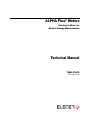
Technical Manual
TM42-2182D
US English (en)
© 2003 by Elster Electricity, LLC. All rights are reserved.
No part of this software or documentation may be reproduced, transmitted, processed or recorded by any means or form,
electronic, mechanical, photographic or otherwise, translated to another language, or be released to any third party
without the express written consent of Elster Electricity, LLC.
Printed in the United States of America.
Notice
The information contained in this software and documentation is subject to change without notice. Product specifications
cited are those in effect at time of publication. Elster Electricity, LLC shall not be liable for errors contained herein or for
incidental or consequential damages in connection with the furnishing, performance, or use of this material. Elster
Electricity, LLC expressly disclaims all responsibility and liability for the installation, use, performance, maintenance and
support of third party products. Customers are advised to make their own indepcendent evaluation of such products.
ALPHA and ALPHA Plus are registered trademarks and Metercat and AlphaPlus are trademarks of Elster Electricity, LLC.
Other product and company names mentioned herein may be the trademarks and/or registered trademarks of their respective owners.
ALPHA Plus Meter Technical Manual
TM42-2182D
Contents
ALPHA Plus Meter Technical Manual
Contents
FCC Compliance . . . . . . . . . . . . . . . . . . . . . . . . . . . . . . . . . . . . . . . . . . . . . vii
Class B Devices . . . . . . . . . . . . . . . . . . . . . . . . . . . . . . . . . . . . . . . . . . . . . . vii
Class A Devices . . . . . . . . . . . . . . . . . . . . . . . . . . . . . . . . . . . . . . . . . . . . . . vii
Telephone Regulatory Information . . . . . . . . . . . . . . . . . . . . . . . . . . . . . . .viii
Disclaimers of Warranties and Limitation of Liability. . . . . . . . . . . . . . . . . ix
Safety Information . . . . . . . . . . . . . . . . . . . . . . . . . . . . . . . . . . . . . . . . . . . . ix
Revisions to this Document . . . . . . . . . . . . . . . . . . . . . . . . . . . . . . . . . . . . xi
1. Introduction . . . . . . . . . . . . . . . . . . . . . . . . . . . . . . . . . . . . . . . . . . . . . 1-1
The ALPHA Plus Meter . . . . . . . . . . . . . . . . . . . . . . . . . . . . . . . . . . 1-2
Standards Compliance. . . . . . . . . . . . . . . . . . . . . . . . . . . . 1-3
Benefits . . . . . . . . . . . . . . . . . . . . . . . . . . . . . . . . . . . . . . . 1-4
Reliability. . . . . . . . . . . . . . . . . . . . . . . . . . . . . . . . 1-4
Maintainability . . . . . . . . . . . . . . . . . . . . . . . . . . . . 1-4
Adaptability . . . . . . . . . . . . . . . . . . . . . . . . . . . . . . 1-4
Economy . . . . . . . . . . . . . . . . . . . . . . . . . . . . . . . 1-4
Security . . . . . . . . . . . . . . . . . . . . . . . . . . . . . . . . 1-5
Accuracy . . . . . . . . . . . . . . . . . . . . . . . . . . . . . . . 1-5
Features . . . . . . . . . . . . . . . . . . . . . . . . . . . . . . . . . . . . . . . . . . . . . 1-6
Standard Features . . . . . . . . . . . . . . . . . . . . . . . . . . . . . . . 1-6
Advanced Features . . . . . . . . . . . . . . . . . . . . . . . . . . . . . . 1-6
Option Boards . . . . . . . . . . . . . . . . . . . . . . . . . . . . . . . . . . 1-7
Power Supply . . . . . . . . . . . . . . . . . . . . . . . . . . . . . . . . . . 1-7
Voltage Ranges. . . . . . . . . . . . . . . . . . . . . . . . . . . 1-7
External Power Supply (A–base Meters Only) . . . . 1-7
Optional Battery . . . . . . . . . . . . . . . . . . . . . . . . . . . . . . . . . 1-8
Meter Types . . . . . . . . . . . . . . . . . . . . . . . . . . . . . . . . . . . . . . . . . . 1-9
Alpha Keys Software . . . . . . . . . . . . . . . . . . . . . . . . . . . . 1-10
2. Product Description . . . . . . . . . . . . . . . . . . . . . . . . . . . . . . . . . . . . . .
System Overview . . . . . . . . . . . . . . . . . . . . . . . . . . . . . . . . . . . . . .
General Theory of Operation . . . . . . . . . . . . . . . . . . . . . . .
Power Supply . . . . . . . . . . . . . . . . . . . . . . . . . . . .
2003.February.27
TM42-2182D
2-1
2-2
2-5
2-5
i
Contents
ALPHA Plus Meter Technical Manual
Voltage and Current Sensing. . . . . . . . . . . . . . . . . 2-6
Meter Engine . . . . . . . . . . . . . . . . . . . . . . . . . . . . 2-6
Microcontroller . . . . . . . . . . . . . . . . . . . . . . . . . . . 2-7
Billing Data . . . . . . . . . . . . . . . . . . . . . . . . . . . . . . . . . . . . 2-7
Metered Energy and Demand Quantities. . . . . . . . 2-7
Average Power Factor . . . . . . . . . . . . . . . . . . . . . 2-8
Demand Calculations . . . . . . . . . . . . . . . . . . . . . . 2-9
Maximum Demand . . . . . . . . . . . . . . . . . . . . . . . 2-11
Demand Forgiveness . . . . . . . . . . . . . . . . . . . . . 2-12
Primary and Secondary Metering . . . . . . . . . . . . 2-12
TOU Data . . . . . . . . . . . . . . . . . . . . . . . . . . . . . . 2-13
Automatic Functions . . . . . . . . . . . . . . . . . . . . . . 2-13
Power Fail Data . . . . . . . . . . . . . . . . . . . . . . . . . . . . . . . . 2-14
Logs and Data Sets . . . . . . . . . . . . . . . . . . . . . . . . . . . . . 2-14
Event Log . . . . . . . . . . . . . . . . . . . . . . . . . . . . . . 2-15
Communications Log . . . . . . . . . . . . . . . . . . . . . 2-15
Voltage Sag Log . . . . . . . . . . . . . . . . . . . . . . . . . 2-16
Load Profile . . . . . . . . . . . . . . . . . . . . . . . . . . . . 2-16
AMR Datalink. . . . . . . . . . . . . . . . . . . . . . . . . . . . . . . . . . 2-18
Physical Description . . . . . . . . . . . . . . . . . . . . . . . . . . . . . . . . . . . 2-19
Cover Assembly. . . . . . . . . . . . . . . . . . . . . . . . . . . . . . . . 2-19
Electronic Assembly. . . . . . . . . . . . . . . . . . . . . . . . . . . . . 2-19
Base Assembly . . . . . . . . . . . . . . . . . . . . . . . . . . . . . . . . 2-20
Physical Dimensions . . . . . . . . . . . . . . . . . . . . . . . . . . . . 2-22
Option Boards . . . . . . . . . . . . . . . . . . . . . . . . . . . . . . . . . . . . . . . 2-24
Internal Telephone Modem Option Board . . . . . . . . . . . . . 2-24
Off–hook Detection . . . . . . . . . . . . . . . . . . . . . . . 2-26
Intrusion Detection . . . . . . . . . . . . . . . . . . . . . . . 2-26
RS-232 Option Board Connections . . . . . . . . . . 2-27
RS-485 Option Board Connections . . . . . . . . . . 2-27
20mA Current Loop Option Board Connections . 2-28
External Serial Communications Option Board
Connections . . . . . . . . . . . . . . . . . . . . . . . . . . . . 2-28
Wide Area Network (WAN) Option Board Connections2-29
3. Operating Instructions . . . . . . . . . . . . . . . . . . . . . . . . . . . . . . . . . . . . 3-1
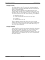
Indicators and Controls. . . . . . . . . . . . . . . . . . . . . . . . . . . . . . . . . . 3-2
LCD. . . . . . . . . . . . . . . . . . . . . . . . . . . . . . . . . . . . . . . . . . 3-2
Quantity Identifier . . . . . . . . . . . . . . . . . . . . . . . . . 3-2
Display Quantity . . . . . . . . . . . . . . . . . . . . . . . . . . 3-3
Display Identifiers . . . . . . . . . . . . . . . . . . . . . . . . . 3-3
Power/Energy Units Identifier . . . . . . . . . . . . . . . . 3-4
Operating Mode Indicator . . . . . . . . . . . . . . . . . . . 3-5
Real Energy Indicators . . . . . . . . . . . . . . . . . . . . . 3-5
Alternate Energy Indicators . . . . . . . . . . . . . . . . . . 3-5
Potential Indicators . . . . . . . . . . . . . . . . . . . . . . . . 3-6
EOI Indicator. . . . . . . . . . . . . . . . . . . . . . . . . . . . . 3-6
Using the Push Buttons . . . . . . . . . . . . . . . . . . . . . . . . . . . 3-6
The RESET Button . . . . . . . . . . . . . . . . . . . . . . . . 3-7
The ALT Button. . . . . . . . . . . . . . . . . . . . . . . . . . . 3-8
The RESET/ALT Mechanism . . . . . . . . . . . . . . . . . 3-9
The TEST Button . . . . . . . . . . . . . . . . . . . . . . . . . 3-9
Clearing Billing Data . . . . . . . . . . . . . . . . . . . . . . 3-10
ii
TM42-2182D
2003.February.27
ALPHA Plus Meter Technical Manual
Contents
Operating Modes . . . . . . . . . . . . . . . . . . . . . . . . . . . . . . . . . . . . .
Normal Mode. . . . . . . . . . . . . . . . . . . . . . . . . . . . . . . . . .
Alternate Mode . . . . . . . . . . . . . . . . . . . . . . . . . . . . . . . .
Test Mode . . . . . . . . . . . . . . . . . . . . . . . . . . . . . . . . . . . .
Error Mode . . . . . . . . . . . . . . . . . . . . . . . . . . . . . . . . . . .
Demand Reset . . . . . . . . . . . . . . . . . . . . . . . . . . . . . . . . . . . . . . .
Demand Reset Lockout . . . . . . . . . . . . . . . . . . . . . . . . . .
3-11
3-11
3-12
3-12
3-13
3-14
3-14
4. Meter Tools . . . . . . . . . . . . . . . . . . . . . . . . . . . . . . . . . . . . . . . . . . . . . 4-1
System Instrumentation . . . . . . . . . . . . . . . . . . . . . . . . . . . . . . . . . 4-2
System Service Tests . . . . . . . . . . . . . . . . . . . . . . . . . . . . . . . . . . . 4-6
Service Voltage Test. . . . . . . . . . . . . . . . . . . . . . . . . . . . . . 4-6
Initiating the Service Voltage Test . . . . . . . . . . . . . 4-8
System Service Locking. . . . . . . . . . . . . . . . . . . . . . . . . . . 4-8
Autolock . . . . . . . . . . . . . . . . . . . . . . . . . . . . . . . . 4-9
Manual Lock . . . . . . . . . . . . . . . . . . . . . . . . . . . . . 4-9
Service Current Test. . . . . . . . . . . . . . . . . . . . . . . . . . . . . 4-10
Initiating the Service Current Test . . . . . . . . . . . . 4-11
System Service Error Codes . . . . . . . . . . . . . . . . . . . . . . 4-12
PQM. . . . . . . . . . . . . . . . . . . . . . . . . . . . . . . . . . . . . . . . . . . . . . . 4-14
Test Definitions. . . . . . . . . . . . . . . . . . . . . . . . . . . . . . . . . 4-14
Momentary Voltage Sag . . . . . . . . . . . . . . . . . . . 4-15
Service Voltage Test . . . . . . . . . . . . . . . . . . . . . . 4-16
Low Voltage Test. . . . . . . . . . . . . . . . . . . . . . . . . 4-16
High Voltage Test . . . . . . . . . . . . . . . . . . . . . . . . 4-17
Reverse Power Test & PF . . . . . . . . . . . . . . . . . . 4-17
Low Current Test . . . . . . . . . . . . . . . . . . . . . . . . 4-18
Power Factor . . . . . . . . . . . . . . . . . . . . . . . . . . . 4-18
Second Harmonic Current Test . . . . . . . . . . . . . . 4-19
Total Harmonic Distortion Current . . . . . . . . . . . . 4-19
Total Harmonic Distortion Voltage . . . . . . . . . . . . 4-19
PQM Event Counters and Timers. . . . . . . . . . . . . . . . . . . 4-20
Voltage Sag Counter and Timer . . . . . . . . . . . . . . . . . . . . 4-20
5. Outputs . . . . . . . . . . . . . . . . . . . . . . . . . . . . . . . . . . . . . . . . . . . . . . . .
Relay Outputs. . . . . . . . . . . . . . . . . . . . . . . . . . . . . . . . . . . . . . . . .
Relay Specifications . . . . . . . . . . . . . . . . . . . . . . . . . . . . . .
Optical Pulse Outputs . . . . . . . . . . . . . . . . . . . . . . . . . . . . . . . . . . .
Output Specifications. . . . . . . . . . . . . . . . . . . . . . . . . . . . .
Activating the Test Mode via Software. . . . . . . . . .
Activating Test Mode via Button Push . . . . . . . . . .
Activating Alternate Mode . . . . . . . . . . . . . . . . . . .
5-1
5-2
5-3
5-5
5-5
5-5
5-6
5-6
6. Testing . . . . . . . . . . . . . . . . . . . . . . . . . . . . . . . . . . . . . . . . . . . . . . . . . 6-1
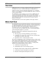
Overview. . . . . . . . . . . . . . . . . . . . . . . . . . . . . . . . . . . . . . . . . . . . . 6-2
Meter Self Test . . . . . . . . . . . . . . . . . . . . . . . . . . . . . . . . . . . . . . . . 6-2
Error Codes and Warnings. . . . . . . . . . . . . . . . . . . . . . . . . 6-3
Error Codes . . . . . . . . . . . . . . . . . . . . . . . . . . . . . 6-3
Warning Codes . . . . . . . . . . . . . . . . . . . . . . . . . . . 6-5
Meter Shop Testing. . . . . . . . . . . . . . . . . . . . . . . . . . . . . . . . . . . . . 6-9
Test Equipment . . . . . . . . . . . . . . . . . . . . . . . . . . . . . . . . . 6-9
Test Setup . . . . . . . . . . . . . . . . . . . . . . . . . . . . . . . . . . . . 6-10
General Test Setup . . . . . . . . . . . . . . . . . . . . . . . . . . . . . 6-11
2003.February.27
TM42-2182D
iii
Contents
ALPHA Plus Meter Technical Manual
Formulas Used in Testing . . . . . . . . . . . . . . . . . . . . . . . . . 6-12
Watt-hour Constant . . . . . . . . . . . . . . . . . . . . . . 6-13
Calculating Meter Accuracy . . . . . . . . . . . . . . . . 6-13
Determining the Power from the Output Pulse Rate6-14
Calculating Power. . . . . . . . . . . . . . . . . . . . . . . . 6-14
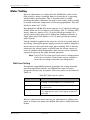
Meter Testing . . . . . . . . . . . . . . . . . . . . . . . . . . . . . . . . . . 6-15
Watt-hour Testing . . . . . . . . . . . . . . . . . . . . . . . . 6-15
VAR-hour Verification . . . . . . . . . . . . . . . . . . . . . 6-16
VA-hour Verification. . . . . . . . . . . . . . . . . . . . . . . 6-17
Installation Site Testing . . . . . . . . . . . . . . . . . . . . . . . . . . . . . . . . . 6-19
Test Mode . . . . . . . . . . . . . . . . . . . . . . . . . . . . . . . . . . . . 6-19
Timing Tests . . . . . . . . . . . . . . . . . . . . . . . . . . . . . . . . . . 6-19
Using the EOI Indicator in Test Mode . . . . . . . . . 6-20
Using the Time Remaining in Subinterval Quantity 6-20
Using the EOI Indicator in Normal Mode . . . . . . . 6-20
Accuracy Tests . . . . . . . . . . . . . . . . . . . . . . . . . . . . . . . . 6-21
Using Pulse Count Display Quantity . . . . . . . . . . 6-21
Counting Pulses Manually . . . . . . . . . . . . . . . . . . 6-22
7. Installation and Removal . . . . . . . . . . . . . . . . . . . . . . . . . . . . . . . . . . 7-1
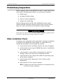
Preliminary Inspection . . . . . . . . . . . . . . . . . . . . . . . . . . . . . . . . . . . 7-2
Meter Installation Check. . . . . . . . . . . . . . . . . . . . . . . . . . . 7-2
Placing the Meter into Service. . . . . . . . . . . . . . . . . . . . . . . . . . . . . 7-3
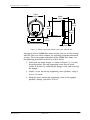
Installing an S-base Meter . . . . . . . . . . . . . . . . . . . . . . . . . 7-3
Installing an A-base Meter . . . . . . . . . . . . . . . . . . . . . . . . . 7-4
Installing an Optional Battery . . . . . . . . . . . . . . . . . . . . . . . 7-7
Initial Setup . . . . . . . . . . . . . . . . . . . . . . . . . . . . . . . . . . . . . . . . . . . 7-9
Removing an ALPHA Plus Meter from Service . . . . . . . . . . . . . . . 7-10
Removing an S-base Meter . . . . . . . . . . . . . . . . . . . . . . . 7-10
Removing an A-base Meter . . . . . . . . . . . . . . . . . . . . . . . 7-10
Removing an Optional Battery . . . . . . . . . . . . . . . . . . . . . 7-11
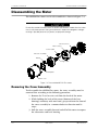
Disassembling the Meter. . . . . . . . . . . . . . . . . . . . . . . . . . . . . . . . 7-12
Removing the Cover Assembly . . . . . . . . . . . . . . . . . . . . 7-12
Removing the Nameplate. . . . . . . . . . . . . . . . . . . . . . . . . 7-13
Removing the Electronic Assembly . . . . . . . . . . . . . . . . . 7-13
Returning the Meter to the Factory . . . . . . . . . . . . . . . . . . . . . . . . 7-14
8. Loss Compensation . . . . . . . . . . . . . . . . . . . . . . . . . . . . . . . . . . . . . . 8-1
Introduction . . . . . . . . . . . . . . . . . . . . . . . . . . . . . . . . . . . . . . . . . . 8-2
What is Loss Compensation? . . . . . . . . . . . . . . . . . . . . . . 8-2
Availability . . . . . . . . . . . . . . . . . . . . . . . . . . . . . . . . . . . . . 8-2
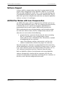
Software Support . . . . . . . . . . . . . . . . . . . . . . . . . . . . . . . 8-3
ALPHA Plus Meters with Loss Compensation . . . . . . . . . . 8-3
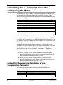
Calculating the % Correction Values for Configuring the Meter . . . . 8-4
Gather Data Necessary for Calculation of Loss Compensation
Parameters . . . . . . . . . . . . . . . . . . . . . . . . . . . . . . . . . . . . 8-4
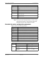
Calculate the meter configuration parameters . . . . . . . . . . 8-5
Line Loss Calculations . . . . . . . . . . . . . . . . . . . . . . . . . . . . . . . . . . 8-8
Input Data Necessary to Calculate Line Losses . . . . . . . . . 8-8
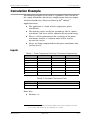
Calculation Example . . . . . . . . . . . . . . . . . . . . . . . . . . . . . . . . . . . 8-11
Inputs . . . . . . . . . . . . . . . . . . . . . . . . . . . . . . . . . . . . . . . 8-11
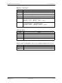
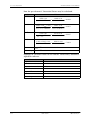
Calculations . . . . . . . . . . . . . . . . . . . . . . . . . . . . . . . . . . . 8-12
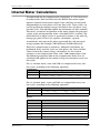
Internal Meter Calculations . . . . . . . . . . . . . . . . . . . . . . . . . . . . . . 8-15
iv
TM42-2182D
2003.February.27
ALPHA Plus Meter Technical Manual
Contents
Meter Outputs . . . . . . . . . . . . . . . . . . . . . . . . . . . . . . . . . . . . . . . 8-17
Introduction . . . . . . . . . . . . . . . . . . . . . . . . . . . . . . . . . . . 8-17
Testing a Meter with Compensation . . . . . . . . . . . . . . . . . 8-17
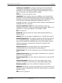
A. Glossary. . . . . . . . . . . . . . . . . . . . . . . . . . . . . . . . . . . . . . . . . . . . . . . . A-1
Glossary . . . . . . . . . . . . . . . . . . . . . . . . . . . . . . . . . . . . . . . . . . . . . A-2
B. Display Table . . . . . . . . . . . . . . . . . . . . . . . . . . . . . . . . . . . . . . . . . . . . B-1
Display Quantities . . . . . . . . . . . . . . . . . . . . . . . . . . . . . . . . . . . . . . B-2
General Display Quantities . . . . . . . . . . . . . . . . . . . . . . . . . B-2
Metered Quantity Dependent Display Quantities . . . . . . . . B-4
System Instrumentation Display Quantities. . . . . . . . . . . . . B-6
ALPHA Plus Meter Display Formats . . . . . . . . . . . . . . . . . . B-7
General Display Quantities . . . . . . . . . . . . . . . . . . B-8
Metered Quantity Dependent Display Quantities . . B-9
System Instrumentation Display Quantities . . . . . B-10
C. Nameplate Information . . . . . . . . . . . . . . . . . . . . . . . . . . . . . . . . . . . . C-1
ALPHA Plus Meter Nameplate . . . . . . . . . . . . . . . . . . . . . . . . . . . . C-2
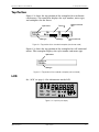
Top Portion . . . . . . . . . . . . . . . . . . . . . . . . . . . . . . . . . . . . C-3
LCD . . . . . . . . . . . . . . . . . . . . . . . . . . . . . . . . . . . . . . . . . . C-3
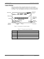
Lower Portion . . . . . . . . . . . . . . . . . . . . . . . . . . . . . . . . . . C-4
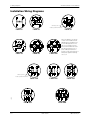
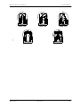
D. Wiring Diagrams . . . . . . . . . . . . . . . . . . . . . . . . . . . . . . . . . . . . . . . . . D-1
Installation Wiring Diagrams . . . . . . . . . . . . . . . . . . . . . . . . D-2
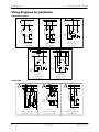
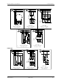
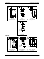
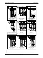
Wiring Diagrams for Installation . . . . . . . . . . . . . . . . . . . . . D-4
E. Technical Specifications . . . . . . . . . . . . . . . . . . . . . . . . . . . . . . . . . . .
Absolute Maximums . . . . . . . . . . . . . . . . . . . . . . . . . . . . .
Operating Ranges . . . . . . . . . . . . . . . . . . . . . . . . . . . . . . .
Operating Characteristics. . . . . . . . . . . . . . . . . . . . . . . . . .
General Performance Characteristics . . . . . . . . . . . . . . . . .
F.
E-1
E-2
E-2
E-2
E-3
Renewal Parts . . . . . . . . . . . . . . . . . . . . . . . . . . . . . . . . . . . . . . . . . . . F-1
Index. . . . . . . . . . . . . . . . . . . . . . . . . . . . . . . . . . . . . . . . . . . . . . . . . . .Index-1
2003.February.27
TM42-2182D
v
Contents
vi
ALPHA Plus Meter Technical Manual
TM42-2182D
2003.February.27
ALPHA Plus Meter Technical Manual
Contents
Contents
TM42-2182D
ALPHA Plus Meter Technical Manual
FCC Compliance
Most ALPHA Plus meters are Class B devices. However, some meters
in some applications, when equipped with certain option boards, are
certified as Class A devices. Additional FCC compliance information
can be found in the documentation shipped with each meter, option
board, kit, or other ALPHA Plus meter component.
Class B Devices
This equipment has been tested and found to comply with the limits
for a Class B digital device, pursuant to part 15 of the FCC Rules.
These limits are designed to provide reasonable protection against
harmful interference in a residential installation. This equipment
generates, uses and can radiate radio frequency energy and, if not
installed and used in accordance with the instructions, may cause
harmful interference to radio communications. However, there is no
guarantee that interference will not occur in a particular installation. If
this equipment does cause harmful interference to radio or television
reception, which can be determined by turning the equipment off and
on, the user is encouraged to try to correct the interference by one or
more of the following measures:
■
reorient or relocate the receiving antenna
■
increase the separation between the equipment and the
receiver
■
connect the equipment into an outlet on a circuit different from
that to which the receiver is connected
■
consult the dealer or an experienced radio/TV technician for
help
Class A Devices
This equipment has been tested and found to comply with the limits
for a Class A digital device, pursuant to part 15 of the FCC Rules.
These limits are designed to provide reasonable protection against
harmful interference when the equipment is operated in a commercial
environment. This equipment generates, uses, and can radiate radio
frequency energy and, if not installed and used in accordance with the
instruction manual, may cause harmful interference to radio
communications. Operation of this equipment on a residential service
may cause harmful interference, in which case the user will be
required to correct the interference at his or her own expense.
2003.February.27
TM42-2182D
vii
Contents
ALPHA Plus Meter Technical Manual
Telephone Regulatory Information
The ALPHA Plus meter internal modem complies with part 68 of the
FCC Rules. A label on the meter nameplate contains the FCC
registration number and ringer equivalence number (REN) for this
equipment. If requested, this information must be provided to the
telephone company. The connection to the telephone network is
through a modular jack USOC RJ-11C.
The REN is used to determine the number of devices that can be
connected to the telephone line. If there is excessive ringer load on
the telephone line, it is possible that a device will not ring in response
to an incoming call. On most lines, but not all, the sum of the RENs
should not exceed 5. To be certain of the number of devices that can
be connected to a line, the local telephone company should be
contacted.
If this equipment causes harm to the telephone network, the
telephone company will notify the user in advance that temporary
discontinuance of service may be required. If advance notice is not
deemed practical, the telephone company will notify the user as soon
as possible thereafter. At that time, the telephone company will also
advise the user of the right to file a compliant with the FCC if believed
to be warranted.
The telephone company may make changes in its facilities,
equipment, operations, or procedures that could affect the operation
of the equipment. If this happens, the telephone company will notify
the user in advance that any necessary modifications can be made to
ensure uninterrupted service.
If the user experiences trouble with this equipment, the Elster
Electricity, LLC RMR Department should be contacted at +1 919 212
4700. If the equipment is causing harm to the telephone network, the
telephone company may request that the equipment be disconnected
until the problem is resolved.
This equipment should not be repaired by unauthorized personnel
except when replacing an entire module. This meter is not intended to
be used on digital PBX lines, party lines, or pay telephone service
provided by the telephone company.
viii
TM42-2182D
2003.February.27
ALPHA Plus Meter Technical Manual
Contents
Disclaimers of Warranties and Limitation of
Liability
There are no understandings, agreements, representations, or
warranties either expressed or implied, including warranties of
merchantability or fitness for a particular purpose, other than those
specifically set out by any existing contract between the parties. Any
such contract states the entire obligation of the seller. The contents of
this technical manual shall not become part of or modify any prior or
existing agreement, commitment, or relationship.
The information, recommendations, descriptions, and safety notices in
this technical manual are based on Elster Electricity, LLC experience
and judgment with respect to operation and maintenance of the
described product. This information should not be considered as allinclusive or covering all contingencies. If further information is
required, Elster Electricity, LLC should be consulted.
No warranties, either expressed or implied, including warranties of
fitness for a particular purpose or merchantability, or warranties
arising from the course of dealing or usage of trade, are made
regarding the information, recommendations, descriptions, warnings,
and cautions contained herein.
In no event will Elster Electricity, LLC be responsible to the user in
contract, in tort (including negligence), strict liability or otherwise for
any special, indirect, incidental, or consequential damage or loss
whatsoever, including but not limited to: damage or loss of use of
equipment, cost of capital, loss of profits or revenues, or claims
against the user by its customers from the use of the information,
recommendations, descriptions, and safety notices contained herein.
Safety Information
Installation, operation, and maintenance of this product can present
potentially hazardous conditions (for example, high voltages) if safety
procedures are not followed. To ensure that this product is used
safely, it is important that you:
2003.February.27
■
Review, understand, and observe all safety notices and
recommendations within this manual.
■
Do not remove or copy individual pages from this manual, as
this manual is intended for use in its entirety. If you were to
remove or copy individual pages, cross-references and safety
notices may be overlooked, possibly resulting in damage to the
equipment, personal injury, or even death.
TM42-2182D
ix
Contents
ALPHA Plus Meter Technical Manual
■
Inform personnel involved in the installation, operation, and
maintenance of the product about safety notices and
recommendations contained in this manual.
Within this manual, safety notices appear preceding the text or step to
which they apply. Safety notices are divided into the following 4
classifications:
Notice is used to alert personnel to installation, operation, or maintenance information
that is important but not hazard related.
Caution is used to alert personnel to the presence of a hazard that will or can cause
minor personal injury, equipment damage, or property damage if the notice is ignored.
Warning is used to alert personnel to the presence of a hazard that can cause severe
personal injury, death, equipment damage, or property damage if notice is ignored.
Danger is used to alert personnel to the presence of a hazard that will cause severe
personal injury, death, equipment damage, or property damage if the notice is ignored.
x
TM42-2182D
2003.February.27
ALPHA Plus Meter Technical Manual
Contents
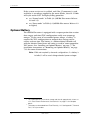
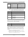
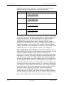
Revisions to this Document
The ALPHA Plus Meter Technical Manual can be referred to by its
document number: TM42-2182. Each revision of this manual is
designated with a letter, with the first revision being “A,” the second
being “B,” and so forth. The document number and revision letter are
located at the bottom of each page.
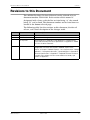
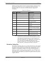
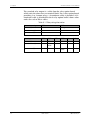
The following table lists the revisions to this document, the date of
release, and a brief description of the changes made.
Revision
Date
Brief description
A
22.July.1997
First release of this document.
B
02.November.1998
Major revisions throughout document.
C
19.July.2000
Corrected figures in Appendix C and Appendix D. Clarified startup
current and secondary time base specifications in Appendix E. Added
FCC Class A device statement.
D
27.February.2003
Changed name of company. Expanded areas in Chapter 2.
Reorganized structure of the chapters. Modified “Optical Pulse
Outputs” in Chapter 5. Added Chapter 8, “Loss Compensation.” Added
Appendix C, “Nameplate Information.” Corrected figures in Appendix D.
Corrected specifications in Appendix E. Replaced old cover and base
assembly style numbers with new cover and base assembly style
numbers in Appendix F.
2003.February.27
TM42-2182D
xi
Contents
xii
ALPHA Plus Meter Technical Manual
TM42-2182D
2003.February.27
ALPHA Plus Meter Technical Manual
TM42-2182D
1. Introduction
ALPHA Plus Meter Technical Manual
1. Introduction
2003.February.27
TM42-2182D
1-1
1. Introduction
ALPHA Plus Meter Technical Manual
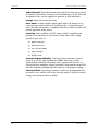
The ALPHA Plus Meter
Upon its introduction in 1992, the ALPHA meter has been the
standard for totally electronic electricity metering. As features have
been continually added, the ALPHA has been able to maintain its
position as the leader in solid state metering. Building on patented
Elster Electricity ALPHA meter technology, the ALPHA Plus meter
provides a meter design platform that supports a variety of metering
requirements.
The ALPHA Plus meter is a totally electronic meter that can perform a
wide range of functions. From a simple one-rate kWh and kW demand
meter up through a multi-rate, real/reactive meter that automatically
validates the meter service connections, provides instrumentation
readings, performs power quality monitoring, and provides load
profile reading with remote communications: the ALPHA Plus meter
does them all.
This meter provides the following general functionality on either a
single rate or time-of-use (TOU) basis:
■
collects energy use and demand data
■
processes energy use and demand data
■
stores energy use and demand data
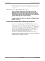
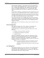
The ALPHA Plus meter meets or exceeds the ANSI standards for
electricity metering, and it is intended for use by industrial and
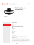
electric utility customers. See Figure 1-1 for an illustration of the
ALPHA Plus meter.
The ALPHA Plus meter may be programmed using Elster Electricity
meter support software at any of the following locations:
■
factory (before shipment)
■
meter shop
■
installation site
A liquid crystal display (LCD) on the meter provides a visual
indication of both energy usage and demand. The optical port allows
data to be retrieved directly from the meter using a handheld or
portable computer. Data can also be collected remotely with
appropriate Elster Electricity meter support software if the meter has
been equipped with an optional communications interface.
1-2
TM42-2182D
2003.February.27
ALPHA Plus Meter Technical Manual
1. Introduction
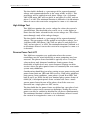
The ALPHA Plus meter may have up to 6 output relays added through
an optional relay board. The following types of output relays are
available:
■
KYZ pulse output
■
load control
■
end of interval
Pkh
Mult. by
Q320F3D0-AD
TYPE A1RL+
PREV
SEAS
RATE
ABCD
CONT
CUM
RESETS
MAX
TOTAL KWARh
SERIAL #
LOCK
TEST
VTR
CTR
:1
:5
TEST
ALT
EOI
O
P
E
N
01 957 166
* KZG001957166
CL20, 120 TO 480V, 4WY or 4WD, 60Hz
FM 9S (8S) Watthour Meter
R?
*
Kh 1.8
P/R 24
TA 2.5A
Figure 1-1. The ALPHA Plus meter
Standards Compliance
The ALPHA Plus meter meets or exceeds the ANSI standards for
electricity metering, and it is intended for use by commercial and
industrial utility customers.
2003.February.27
Number
Date
Title
C12.1
1995
American National Standard for Electric Meters –
Code for Electricity Metering
C12.10
1997
Electromechanical Watthour Meters
TM42-2182D
1-3
1. Introduction
ALPHA Plus Meter Technical Manual
Number
Date
Title
C12.20
1998
American National Standard for Electricity Meters
0.2 and 0.5 Accuracy Classes
Benefits
Reliability
Unlike electromechanical meters, the ALPHA Plus meter has no
moving parts. This results in improved service reliability and ensures
many years of trouble-free service. Both EEPROM and RAM are used
to store meter data. The RAM has power backup supplied by a
supercapacitor which is integral to the meter main board. An optional
lithium battery can be installed to prevent data and time loss during
an extended power outage.
The ALPHA Plus meter uses the power line frequency to maintain
time and date functions. In configurations where the line frequency is
known to be unstable, the ALPHA Plus meter can be programmed to
always use its internal crystal oscillator for keeping accurate time.
The ALPHA Plus meter contains circuits which have been designed to
function with the battery to provide a long battery life. Because of the
low current drain, the service life of the lithium battery is expected to
exceed the life of the meter.
Maintainability
The ALPHA Plus meter is easy to maintain. Meter and register
functions are fully integrated on a single, surface-mount technology
circuit board. This combines with the modular design of the meter to
allow parts to be replaced quickly and easily.
Adaptability
The ALPHA Plus meter allows configuration for custom TOU rates,
offering a broad range of demand and time-of-use operations. Almost
all common services and mounting configurations have been
accounted for, and functional upgrades are easily performed as new
situations arise. The wide operating voltage range allows installation
at any of the common meter voltages.
Economy
The ALPHA Plus meter saves both time and money. It will dramatically
increase personnel productivity due to the following features:
1-4
■
no user calibration required (factory calibrated)
■
reduced testing times
TM42-2182D
2003.February.27
ALPHA Plus Meter Technical Manual
1. Introduction
■
fewer styles to learn and maintain
■
automated data retrieval
■
system service verification
■
on site instrumentation displays
■
power quality monitoring (PQM) tests
Security
The ALPHA Plus meter is tamper resistant. Passwords may be
specified which prevents unauthorized access to meter data. Since
there are no moving parts in this fully electronic meter, tampering
which would affect an electromechanical meter will not affect the
ALPHA Plus meter.
The optional PQM feature can also be used to detect conditions which
may result from meter tampering designed to affect energy
measurement. All ALPHA Plus meters provide auditing capabilities in
order to indicate potential meter tampering. These capabilities provide
a record of the following:
■
programming changes
■
power outages
■
number of manual demand resets
■
many other security related quantities available on TOU meters
Accuracy
The ALPHA Plus meter meets or exceeds requirements of ANSI
standards. The meter precisely measures and displays energy usage
and demand data consistent with the meter class purchased, and
through a wide range of the following:
■
current variations
■
voltage variations
■
temperature variations
■
power factor variations
The low current sensor burden may also improve the accuracy of
external current transformers when measuring light loads.
2003.February.27
TM42-2182D
1-5
1. Introduction
ALPHA Plus Meter Technical Manual
Features
Standard Features
The ALPHA Plus meter comes with many options that make it a
powerful meter:
■
fully programmable
■
pre–programmed at the factory
■
wide operating ranges for voltage, current, and temperature
■
per phase values for
■
kW
■
kVA or kVAR
■
voltage and voltage angle
■
current and current angle
■
power factor and power factor angle
■
for TOU meters, up to 4 rate periods
■
average power factor
■
high accuracy internal clock
■
polycarbonate enclosure
■
easily upgradeable through software and optional hardware
■
easy access battery
Advanced Features
There are also some advanced options that are available. All of these
are part of the main meter board:
1-6
■
load profile with up to 4 channels
■
power quality monitoring
■
transformer and line loss compensation
■
4–quadrant metering
TM42-2182D
2003.February.27
ALPHA Plus Meter Technical Manual
1. Introduction
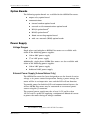
Option Boards
The following option boards are available for the ALPHA Plus meter:
■
output relay option board
■
communications
■
internal modem option board
■
external serial communications option board
■
RS-232 option board1
■
RS-485 option board1
■
20mA current loop option board
■
wide area network (WAN) option board1
Power Supply
Voltage Ranges
Single phase and polyphase ALPHA Plus meters are available with
either of the following power supplies:
■
120 to 480V power supply
■
57 to 240V power supply
Additionally, single phase ALPHA Plus meters are also available with
either of the following power supplies:
■
120 to 240V power supply
■
dedicated 240V power supply
External Power Supply (A–base Meters Only)
The ALPHA Plus meter has been designed to use the electrical service
voltage as its power source for operation. During a power outage, the
meter will be in an inoperative state and the LCD will not function.
To provide power for both the LCD and communication features, the
A-base ALPHA Plus meter may be connected to an external power
source using the J5 connector.
The external power supply must be at least 12.5V and less than
16V DC and is capable of supplying a minimum of 100mA of current
to power the meter during an outage condition.
1
2003.February.27
Not available on single phase 240V ALPHA Plus meters.
TM42-2182D
1-7
1. Introduction
ALPHA Plus Meter Technical Manual
If the system service test is enabled, and if the J5 connector is used,
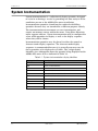
and there is no voltage supplied to the meter blades, then 6(U will cycle on the LCD. To display billing quantities:
■
see “Normal mode” in Table 3-4 (ALPHA Plus meters Release
2.0 and 2.1)
■
see “Error mode” in Table 3-4 (ALPHA Plus meters Release 2.2
or higher)
Optional Battery
The ALPHA Plus meter is equipped with a supercapacitor that sustains
data storage and time (TOU configurations only) over temporary
outages.2 In the event of an extended power outage, a battery3 is
required by TOU configurations to maintain data storage and to
ensure accurate time. The battery is a lithium thionyl chloride cell
with the identical form factor and rating as used in some competitive
TOU meters. See “Installing an Optional Battery” on page 7-7 for
installation instructions or “Removing an Optional Battery” on page
7-11 for removal instructions.
Note: While not required by demand configurations, if a battery is
installed, it will be used during extended power outages.
2
3
1-8
The supercapacitor sustains data storage and time for approximately 6 hours at
25°C. See “General Performance Characteristics” on page E-3 for complete
details.
The battery can be ordered from Elster Electricity, LLC. See Appendix F, “Renewal
Parts,” for style numbers.
TM42-2182D
2003.February.27
ALPHA Plus Meter Technical Manual
1. Introduction
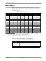
Meter Types
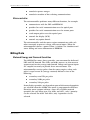
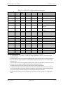
Different ALPHA Plus meters have specific capabilities. Table 1-1
identifies all the possible meter types. Descriptions of the suffixes can
be seen in Table 1-3.
Table 1-1. ALPHA Plus meter types
Type
kWh
A1D+
✓
A1T+
✓
✓
A1R+
A1K+
✓
A1TL+
✓
A1RL+
✓
A1KL+
✓
A1DQ+
✓
A1TQ+
✓
A1RQ+
✓
A1KQ+
✓
A1TLQ+
✓
A1RLQ+
✓
kVARh
kVAh
LC
Quantities
✓
1
✓
✓
2
✓
✓
3
✓
2
✓
✓
1
✓
✓2
✓
✓
2
✓
3
✓
✓
2
✓
✓
1
✓
✓
1
✓
✓
2
✓
✓
2
✓
✓3
✓
✓
2
✓
✓
✓
1
✓
✓
2
✓
✓
✓
2
✓
✓
✓
2
✓
✓
✓
✓
✓
A1RLCQ+
✓
✓
✓
3.
PQM
✓2
A1KLQ+
2.
LP1
1
✓3
1.
TOU
✓
2
12K for ALPHA Plus meters Release 2.0 or 2.1; 28K for ALPHA Plus meters Release 2.2 or higher
kVAh and kVA quantities calculated vectorially from kWh and kVARh.
kVAh and kVA quantities measured and calculated arithmetically.
There are 4 basic types of meters, as shown below:
Table 1-2. ALPHA Plus basic meter types
2003.February.27
Meter type
Description of functions
A1D+
Measures watts (W) and watthours (Wh)
A1T+
Measures W and Wh on a time–of–use basis
A1K+
Measures Wh and apparent energy (VAh)
A1R+
Measures Wh and reactive energy (VARh)
TM42-2182D
1-9
1. Introduction
ALPHA Plus Meter Technical Manual
The additional functions can be applied to the various meter
configurations:
Table 1-3. ALPHA Plus meter type suffixes
Suffix
Added
T
Time–of–use (TOU); A1K+ and A1R+ also have TOU capabilities
L
Load profile (LP)
Q
Power quality monitoring (PQM)
C
Transformer and line loss compensation (LC)
Alpha Keys Software
Alpha Keys software allows ALPHA Plus meters to be upgraded so
they provide additional functionality. Upgrading with Alpha Keys
software means that the meter does not have to be returned to the
factory and that new meters do not have to be purchased to gain
functionality. Alpha Keys software may be used as a standalone
program or with Elster Electricity meter support software.
The following types of upgrades may be performed with Alpha Keys
software:
Table 1-4. Meter type upgrades
Current meter type
Can be upgraded to
A1D+
A1T+
A1K+
A1R+
A1T+
A1K+
A1R+
A1K+
A1R+
A1R+
A1K+
In addition, the following options can be added to the meter using
Alpha Keys:
Table 1-5. Configuration option upgrades
Additional function
Can be added to
Power quality monitoring
A1D+
A1T+
A1K+
A1R+
Load profile storage
A1T+
A1K+
A1R+
Note: Transformer and line loss compensation is available only at
the time of original manufacture and cannot be added using
an Alpha Key.
1-10
TM42-2182D
2003.February.27
ALPHA Plus Meter Technical Manual
TM42-2182D
2. Product Description
ALPHA Plus Meter Technical Manual
2. Product Description
2003.February.27
TM42-2182D
2-1
2. Product Description
ALPHA Plus Meter Technical Manual
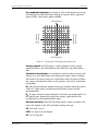
System Overview
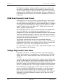
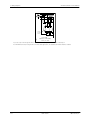
The ALPHA Plus meter main circuit board contains all the electronics
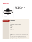
that make up the meter and integral registers. See Figure 2-1 for the
wide voltage range meter circuit board block diagram. The circuit
board for the wide voltage range meter as shown in Figure 2-2
contains the following components:
■
meter engine and reset circuitry
■
microcontroller
■
EEPROM
■
resistive dividers for the 3 phase voltages
■
load resistors for the 3 current sensors
■
power supply
■
high frequency crystal oscillator
■
32 kHz low power, timekeeping crystal oscillator
■
optical port components
■
liquid crystal display (LCD) interface
■
option board interface
Phase A
Voltage
5V linear
power
supply
Wide input
12V power
supply
Non
volatile
supply
Battery
2.5V
precision
reference
LCD
Watch
crystal
Resistive
divider
Power Fail
Phase B
Voltage
Resistive
divider
2x Line Freq
Phase C
Voltage
Resistive
divider
A
B
C
Phase A
Current
Sensor
Phase B
Current
Sensor
Phase C
Current
Sensor
Meter
engine
Wh Del
Wh Rec
VARh Del
VARh Rec
Microcontroller
Clock
Crystal
EEPROM
Option
connector
Optical
port
Figure 2-1. Wide voltage range meter circuit board block diagram
2-2
TM42-2182D
2003.February.27
ALPHA Plus Meter Technical Manual
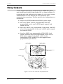
2. Product Description
Wide operating
range power supply
J5 connector for
external power supply
Microcontroller
Voltage connection
Option board interface
Meter engine
Magnetic reed switch
Current sensor
connection
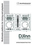
Figure 2-2. Wide operating range meter main circuit board
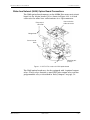
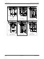
See Figure 2-3 for the 240V meter circuit board block diagram. The
circuit board for the wide voltage range meter as shown Figure 2-4 in
contains the following components:
2003.February.27
■
meter engine and reset circuitry
■
microcontroller
■
EEPROM
■
resistive divider for 1 phase voltage
■
load resistor for 1 current sensor
■
power supply
■
high frequency crystal oscillator
■
32 kHz low power, timekeeping crystal oscillator
■
optical port components
■
liquid crystal display (LCD) interface
■
option board interface
TM42-2182D
2-3
2. Product Description
ALPHA Plus Meter Technical Manual
Phase A
Voltage
5V linear
power
supply
240V
transformer
Non
volatile
supply
Battery
2.5V
precision
reference
LCD
Watch
crystal
Resistive
divider
Power Fail
2x Line Freq
Meter
engine
Phase A
Current
A
Wh Del
Wh Rec
VARh Del
VARh Rec
Sensor
Microcontroller
Clock
Crystal
EEPROM
Option
connector
Optical
port
Figure 2-3. 240V meter circuit board block diagram
2-4
TM42-2182D
2003.February.27
ALPHA Plus Meter Technical Manual
2. Product Description
T1 transformer
240V power
supply
C35
T1
U3A
D15
J5 connector
D14
D13
U3
D12
C10
J5
D10
D10
D10
1
C2A C2
J6
XTAL1
U1
Microcontroller
R12
Voltage
connection
C4
R56
R55
41
R20
R19
R34
R35
1
2
40
CLK
39
R33
J4
29
40
28
R36
XTAL2
U2
18
1
R88
R86
C18
R32
C44
C17
U6
1
C49
W1
R93
17
C50
7
5D25265
SW4
R54
R58
R15
20
6
J2
1
U5
U4
Option board
interface
OPT1
D11
Magnetic reed
switch
Meter engine
J3
Current sensor
connection
Figure 2-4. 240V meter main circuit board
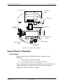
General Theory of Operation
Power Supply
Power is supplied to the ALPHA Plus meter using one of the
following:
■
a wide voltage range power supply
■
a transformer that covers 240V applications only
Phase A voltage must be present to power the meter circuitry. The 12V
output from the power supply is then fed to a low voltage linear
regulator to attain the logic level voltage.
2003.February.27
TM42-2182D
2-5
2. Product Description
ALPHA Plus Meter Technical Manual
Voltage and Current Sensing
The power line currents and voltages are sensed using specialized
current sensors and resistive voltage dividers respectively.
Multiplication and other calculations are performed using the meter
engine. This meter engine contains a digital signal processor (DSP)
with built in analog-to-digital (A/D) converters capable of sampling
each voltage and current input.
The electronic assembly receives each phase voltage through resistive
dividers to ensure that a linear logic level voltage is maintained. This
also serves to minimize phase shift over a wide dynamic range. The
meter engine within the electronic assembly samples the scaled inputs
provided by the resistive dividers to provide accurate voltage
measurement.
The electronic assembly receives each phase current through a
precision wound current sensor which reduces the line current
proportionally. The meter engine within the electronic assembly
samples the individual phase currents to provide accurate current
measurement.
Meter Engine
Multiplication and other calculations are performed using a custom
integrated circuit, called the meter engine. The meter engine contains
the digital signal processor (DSP) with built–in analog–to–digital
(A/D) converters capable of sampling each current and voltage input.
The A/D converters measure the voltage and current inputs for a
given phase. The DSP multiplies the signals appropriately, using the
factory–programmed calibration constants that are stored in EEPROM.
The meter engine includes power failure circuitry that responds to any
power failure greater than 100ms in duration. The meter engine
processes voltages and currents into energy pulses, which are then fed
to the microcontroller for processing. All information necessary to
ensure the integrity of the demand or TOU calculations is stored in the
EPPROM, including the following:
2-6
■
configuration data
■
constants
■
energy usage
■
maximum demand
■
cumulative demand
■
all TOU data
■
number of demand resets
TM42-2182D
2003.February.27
ALPHA Plus Meter Technical Manual
2. Product Description
■
cumulative power outages
■
cumulative number of data–altering communications
Microcontroller
The microcontroller performs many different functions, for example:
■
communicates with the DSP and EEPROM
■
provides for serial communication over the optical port
■
provides for serial communication over the remote ports
■
sends output pulses over the optical port
■
controls the display (LCD)
■
controls any option boards
The microcontroller and the meter engine communicate with each
other constantly to process voltage and current inputs. When the
microcontroller detects a power failure, it initiates the shutdown and
stores billing and status information in EEPROM.
Billing Data
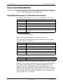
Metered Energy and Demand Quantities
The ALPHA Plus meter always provides a measurement for delivered
kWh and kW demand. The A1K+ and A1R+ meters can also measure
apparent and reactive energy and demand. Voltage and current inputs
are sampled accurately to provide these measurements. The
microcontroller receives pulses from the meter engine, where each
pulse is equal to one Ke (energy constant) defined as one of the
following:
■
secondary rated Wh per pulse
■
secondary VARh per pulse
■
secondary VAh per pulse
Some display quantities are dependent upon which metered quantities
are selected when the ALPHA Plus meter is programmed with Elster
Electricity meter support software. shows the available metered
quantities for each meter type. For A1D+ and A1T+, only 1 quantity
can be selected. For A1K+ and A1R+, only 2 quantities can be
selected.
2003.February.27
TM42-2182D
2-7
2. Product Description
ALPHA Plus Meter Technical Manual
Table 2-1. Metered quantities by meter type
Quantity
A1D+, A1T+
A1K+
A1R+
kW delivered
✓
✓
✓
kW received
✓
✓
✓
kW sum
✓
✓
✓
kVA delivered (Q1+Q4)
✓
✓2
kVA received (Q2+Q3)
✓
✓2
kVA sum (delivered + received)
✓
kVA Q1
✓2
kVA Q2
✓2
kVA Q3
✓
kVA Q4
✓2
kVAR delivered (Q1+Q4)
✓
kVAR received (Q2+Q3)
✓
kVAR sum (delivered + received)
✓
kVAR Q1
✓1
kVAR Q2
✓
kVAR Q3
✓1
kVAR Q4
✓1
kVAR Q1 + Q4
✓
2
✓
kVAR Q2 + Q3
✓2
✓
1.
2.
2
1
kVARh values for each quadrant are available whether selected as a metered quantity or not.
ALPHA Plus meters Release 2.2 or higher only.
Average Power Factor
A1K+ and A1R+ meters Release 2.2 or higher can calculate the average
power factor from collected energy-use data. The two metered
quantities selected in Elster Electricity meter support software must be
kWh and kVAh to get AvgPF. Average power factor (AvgPF) is
calculated by the meter using kWh and kVAh values since the most
recent demand reset with the following formula:
Avg PF =
2-8
TM42-2182D
kWh
kVAh
2003.February.27
ALPHA Plus Meter Technical Manual
2. Product Description
Average power factor will be calculated once every second. The kWh
and kVAh values used in this calculation will be set to zero upon a
demand reset and AvgPF will be set to a value of 1.000. Average
power factor will not be calculated while the ALPHA Plus meter is in
test mode.
Note: Since kVAh and kWh must be selected to obtain AvgPF,
kVARh and average power factor are mutually exclusive.
Demand Calculations
Demand is the average value of power over a specified interval of
time. The ALPHA Plus meter supports three different methods for
demand calculation:
■
rolling interval
■
block interval
■
thermal time constant
An interval is the time in which demand is calculated. The length of a
demand interval is programmable using Elster Electricity meter
support software, but the value must be evenly divisible into an hour.
Common demand interval lengths are 15 or 30 minutes.
Rolling Interval
Rolling demand is defined by two parameters: the demand interval
length and the subinterval length.
■
The demand interval length is specified in minutes and may be
any value that is evenly divisible into 60.
■
The demand subinterval length is also specified in minutes and
may be any value that is evenly divisible into the interval
length.
Both of these values are configurable by Elster Electricity meter
support software. The demand is calculated at the end of each
subinterval, resulting in overlapping demand intervals (or a rolling
demand).
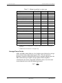
For example, the ALPHA Plus meter can be configured for a 15.minute
demand interval length and a 5.minute subinterval length. In this case,
the demand is calculated every 5 minutes based on the 3 previous
subintervals (see Figure 2-5).
2003.February.27
TM42-2182D
2-9
2. Product Description
ALPHA Plus Meter Technical Manual
15 minute interval
15 minute interval
15 minute interval
subinterval
0
subinterval
5
subinterval
subinterval
10
15
minutes
subinterval
20
25
Figure 2-5. Rolling demand intervals
The block interval calculates demand by using the following equation:
D=
total accumulated energy
t hours
For example, if the demand interval is 15 minutes and the total
accumulated energy is 50kWh, then the demand is 200kW.
D=
50 kWh
= 200 kW
.25h
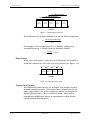
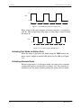
Block Interval
Block interval demand is a special case of rolling interval demand in
which the subinterval is the same size as the interval (see Figure 2-6).
0
interval
interval
interval
interval
subinterval
subinterval
subinterval
subinterval
15
30
minutes
45
60
Figure 2-6. Block demand intervals
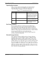
Thermal Time Constant
The ALPHA Plus meter Release 2.2 or higher also provides thermal
demand emulation features. This feature stores demand data based
upon a logarithmic scale which accurately emulates the function of
thermal demand meters. This is useful for utilities which will be
incorporating ALPHA Plus meters in environments which already
include thermal demand meters.
2-10
TM42-2182D
2003.February.27
ALPHA Plus Meter Technical Manual
2. Product Description
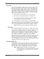
Maximum Demand
Maximum demand (also referred to as indicating demand) is the
highest demand value that occurs in a billing period. The demand for
each demand interval is calculated and compared to an earlier
maximum demand value. If the new interval demand exceeds the
previous maximum demand, then the new demand is stored as the
maximum demand (see Figure 2-7). When a demand reset occurs, the
maximum demand is reset to zero. The demand for the first full
interval after a demand reset becomes the maximum demand.
Previous max
demand (9.7kW)
Interval 1
demand
(9.2kW)
New max
demand (9.9kW)
Previous max
demand (9.9kW)
Interval 2
demand
(9.9 kW)
Interval 3
demand
(9.5 kW)
Figure 2-7. Indicating maximum demand
In addition to maximum demand, the ALPHA Plus meter also stores
either the cumulative or continuous cumulative demand. A1K+ and
A1R+ meters can be programmed to trigger the recording of a
coincident demand.
Cumulative Maximum Demand
Cumulative maximum demand adds the present maximum demand to
the cumulative sum of earlier billing period maximum demand values
each time a demand reset is performed. This provides a cumulative
number which reflects all of the previous billing period maximum
demand values in summation. It can also serve as a security feature
for detecting unauthorized demand resets during a billing period.
Cumulative demand can also be helpful in recreating billing data in
the event of billing data record loss following a reading. The result of
subtracting the previous cumulative demand from the present
cumulative demand will yield the maximum demand for the previous
complete billing period.
2003.February.27
TM42-2182D
2-11
2. Product Description
ALPHA Plus Meter Technical Manual
Continuous Cumulative Maximum Demand
Continuous cumulative maximum demand works similarly to
cumulative maximum demand. Continuous cumulative demand,
however, is always equal to the sum of the previous billing period
continuous cumulative demand and the current maximum demand.
Coincident Demand
Coincident demand refers to a demand value that occurs at the same
time as another demand reaches its peak value. For example, an
electric utility may want to record the kVAR demand at the time of a
maximum kW demand. This requires that kVAR demand be stored and
reported during the same interval as the maximum kW demand.
Demand Forgiveness
Demand forgiveness is the time during which demand is not
calculated or stored after a power outage. Demand forgiveness has
two programmable settings:
■
the number of minutes a power outage must last to qualify for
demand forgiveness (zero to 15 minutes)
■
the number of minutes that demand is not calculated or stored
(zero to 255 minutes) following a qualified power outage
If demand forgiveness is programmed on an A1D+ meter, any power outage will result in
the forgiveness time being applied.
Primary and Secondary Metering
The ALPHA Plus meter can be programmed for either primary or
secondary metering. Primary metering results in the measured energy
and demand quantities being multiplied by voltage and current
transformer ratios for that meter location. The displayed quantities on
the LCD would then reflect energy and demand on the primary side of
the instrument transformers. These ratios would be programmed into
the meter with Elster Electricity meter support software.
If the transformer multiplier (product of both the voltage and current
transformer ratios) creates a factor larger than can be stored within
the ALPHA Plus meter, an external display multiplier will be required.
Elster Electricity meter support software can be used to program the
2-12
TM42-2182D
2003.February.27
ALPHA Plus Meter Technical Manual
2. Product Description
meter with a preferred external display multiplier when displaying
quantities on the LCD. The displayed quantities will not be valid
unless multiplied by this external display multiplier manually at the
time of reading.
Secondary metering does not take into account voltage or current
transformer ratios. Even if voltage and current transformer values are
programmed into the meter with Elster Electricity meter support
software, the displayed quantities on the LCD would reflect energy
and demand on the secondary side of the instrument transformers.
TOU Data
Some ALPHA Plus meters are equipped with TOU capabilities. These
meters may be used as either single-rate or TOU meters. Up to 4 TOU
rates may be defined. According to the TOU rate schedule which was
programmed into the meter, these TOU rates may be based upon
either day, time, or season changes.
In TOU configurations, meter data is accumulated during individual
TOU rate periods and displayed as energy and demand values on the
LCD for the specified rate. Demand intervals are synchronized to
whole hour or evenly divisible fractional hour time periods according
to real-time. A1R+ and A1K+ meters store the selected metered
quantities according to the TOU rate configuration.
Note: If Alpha Keys software was used to upgrade an A1D+
meter to include TOU capabilities, a lithium battery1 will be
required.
Automatic Functions
The ALPHA Plus meter may be programmed with Elster Electricity
meter support software to perform the following functions
automatically:
■
demand forgiveness after a power interruption
■
demand reset after season change (TOU configurations only)
■
autoread and demand reset (TOU configurations only):
■
1
2003.February.27
■
specified day of month
■
specified number of days after most recent demand reset
■
ALPHA Plus meters Release 2.2 or higher support autoread
without performing a demand reset
perform system service tests:
The lithium battery can be ordered from Elster Electricity. See Appendix F,
“Renewal Parts,” for style numbers.
TM42-2182D
2-13
2. Product Description
ALPHA Plus Meter Technical Manual
■
■
upon power restoration after a failure or initial power–up
■
every 24 hours (A1D+) or at midnight (TOU configurations
only)
■
following data–altering communications
■
during normal or alternate mode sequences with system
service tests
perform PQM background tests on a continual basis on meters
with the optional PQM feature
Power Fail Data
The ALPHA Plus meter monitors and records the total power failure
data. The following information is recorded:
■
cumulative number of power failures
■
cumulative duration of all power failures (TOU meters)
■
start date and time of the most recent power failure (TOU
meters)
■
end date and time of the most recent power failure (TOU
meters)
These values can be programmed to display on the LCD using Elster
Electricity meter support software. See Appendix B, “Display Table,”
for more information about displayable items.
The cumulative number of power failures rolls over to zero after 9,999
total outages have been recorded.
Logs and Data Sets
The ALPHA Plus meter records the following types of logs and data
sets:
2-14
■
event log
■
communications log
■
voltage sag log (ALPHA Plus Release 2.2 only)
■
load profile
TM42-2182D
2003.February.27
ALPHA Plus Meter Technical Manual
2. Product Description
Event Log
Up to 255 date and time stamped entries for various events can be
stored on an ALPHA Plus meter which has the load profile feature.
Elster Electricity meter support software can be used to define and
program the ALPHA Plus meter for the number of event log entries
which will be recorded. When the maximum amount of event log
entries has been stored, the meter will begin overwriting the oldest
entries. Events included in this log are:
■
power failure start and stop times (2 event log entries)
■
date and time change information (2 event log entries)
■
date and time of manually performed or communicationinitiated demand resets (1 event log entry)
■
date and time of test mode activity (2 event log entries)
Since load profile data can share this memory, more event log entries
results in less available space for load profile data. The event log may
also be disabled through Elster Electricity meter support software.
Note: PQM tests may also create entries within the event log.
PQM entries
The event log records the date and time that a PQM test detects the
start and end of a PQM test failure. The start time is logged as when
the minimum duration time has been exceeded. The stop time is
logged as soon as the PQM test no longer fails. Momentary voltage sag
test log entries are contained in a separate voltage sag log and are
only available for ALPHA Plus meters Release 2.2 or higher.
Since the event log uses load profile memory for the log entries, load
profile must be a feature of the meter in order for event logging to
occur. A maximum of 255 events can be recorded for all monitors
except the momentary voltage sag test. The event log may be cleared
using Elster Electricity meter support software.
Communications Log
The ALPHA Plus meter records the cumulative number of data-altering
communications. This number will roll over to zero after 99 total
communications. For TOU configurations, the date and time of the
most recent data-altering communications will also be recorded.
Note: Programming an ALPHA Plus meter will reset the
communications log, and the programming session will not
be counted within the cumulative number of data-altering
communications.
2003.February.27
TM42-2182D
2-15
2. Product Description
ALPHA Plus Meter Technical Manual
Voltage Sag Log
The voltage sag log will contain the date, time, and phase (or phases)
of any momentary voltage sag detected. The voltage sag log is
available on ALPHA Plus Release 2.2 or higher and only if the meter
has the PQM option.
Since a momentary voltage sag does not typically last very long, the
log will contain just once date/time stamp to indicate the occurrence.
Start and stop times are not recorded. If multiple voltage sags occur
on the same phase within a one second interval, then only a single
event will be recorded.
The voltage sag log is fixed at 40 log entries. Once the log is full, the
oldest records will be overwritten with new ones. The voltage sag log
can be cleared using Elster Electricity meter support software.
Since the voltage sag log uses load profile memory for the log entries,
load profile must be a feature of the meter in order for event logging
to occur.
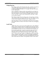
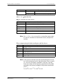
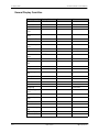
Load Profile
ALPHA Plus meters may have the load profile feature with additional
storage memory added to them for recording interval-by-interval data.
A maximum of 4 channels may be recorded. Each load profile interval
on the ALPHA Plus meter can store a maximum of 32,766 pulses. If
the intended application is expected to generate more than 32,766
pulses per interval, apply a divisor to the load profile data when
configuring the meter with Elster Electricity meter support software.
The “L” meter type suffix signifies an ALPHA Plus meter having load
profile capability. Load profile is stored in 12K (28K on ALPHA Plus
meters Release 2.2 or higher) of the nonvolatile EEPROM on the meter
main circuit board. See Table 2-2 for quantities which can be stored.
2-16
TM42-2182D
2003.February.27
ALPHA Plus Meter Technical Manual
2. Product Description
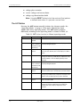
Table 2-2. Quantities available for load profile storage
Quantity
A1TL+
A1KL+
A1RL+
kW delivered
✓
✓
✓
kW received
✓
✓
✓
kW sum
✓1
✓1
✓1
kVAR delivered (Q1 + Q2)
✓
kVAR received (Q3 + Q4)
✓
kVAR sum (delivered + received)
✓1
kVA delivered (Q1 + Q4)
✓
kVA received (Q2 + Q3)
✓
kVA sum (delivered + received)
✓
✓1,2
✓
1,2
1
kVAR Q1
✓
kVAR Q2
✓
kVAR Q3
✓
kVAR Q4
✓
kVA Q1
✓1,2
kVA Q2
✓1,2
kVA Q3
✓1,2
kVA Q4
✓1,2
kVAR Q1 + Q4
✓1,2
✓1
kVAR Q2 + Q3
✓1,2
✓1
1.
2.
Must select as a metered quantity to be stored as load profile.
ALPHA Plus meters Release 2.2 or higher
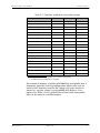
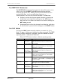
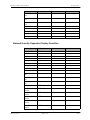
The amount of memory available in EEPROM for load profile data is
dependent upon the event log configuration. PQM events also are
stored in this location except for the voltage sag events which are
stored in a separate voltage sag log (ALPHA Plus Release 2.2 or
higher). See Table 2-3 for a general idea of how much load profile
data can be stored in available memory.
2003.February.27
TM42-2182D
2-17
2. Product Description
ALPHA Plus Meter Technical Manual
.
Table 2-3. Load profile storage capacity
ALPHA Plus meters Release 2.2 and higher
1 channel
2 channels
4 channels
Interval (minutes)
5
15
30
5
15
30
5
15
30
Maximum days1
48
141
255
24
71
141
12
36
71
Minimum days2
44
132
255
22
67
132
11
33
67
ALPHA Plus meters Release 2.0 and 2.1
1 channel
Interval (minutes)
Maximum days
1
Minimum days2
1.
2.
2 channels
4 channels
5
15
30
5
15
30
5
15
30
21
61
119
10
31
61
5
15
31
17
52
102
9
26
52
4
13
26
No event log entries
255 event log entries
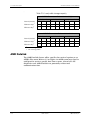
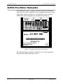
AMR Datalink
The AMR Datalink feature offers specific data retrieval options to an
ALPHA Plus meter Release 2.2 or higher. An AMR system may then be
configured to retrieve specific data from a meter, instead of a full
diagnostic read. AMR Datalink can potentially reduce total
communication time.
2-18
TM42-2182D
2003.February.27
ALPHA Plus Meter Technical Manual
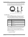
2. Product Description
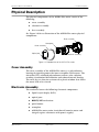
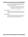
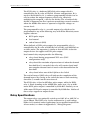
Physical Description
The physical components of the ALPHA Plus meter consist of the
following:
■
cover assembly
■
electronic assembly
■
base assembly
See Figure 2-8 for an illustration of the ALPHA Plus meter physical
components.
Base assembly
Nameplate
Cover assembly
Optical port
Electronic assembly
RESET
ALT
Figure 2-8. Exploded view of the ALPHA Plus meter
Cover Assembly
The cover assembly of the ALPHA Plus meter is a polycarbonate
housing designed to protect the inner assemblies of the meter. The
ultraviolet (UV) stabilized polycarbonate reflects solar radiation,
resulting in minimized discoloration and reduced internal heating.
The cover has an abrasion resistant clear plastic window that allows
the meter LCD to be viewed.
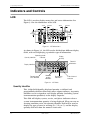
Electronic Assembly
The enclosure houses the following electronic components:
2003.February.27
■
liquid crystal display (LCD)
■
optical port
■
RESET/ALT mechanism
■
push buttons
■
nameplate
■
ALPHA Plus meter main circuit board (contains meter and
integral register electronics with power supply)
TM42-2182D
2-19
2. Product Description
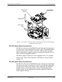
ALPHA Plus Meter Technical Manual
The enclosure also accommodates the following optional electronic
components:
■
optional lithium battery
■
relay option board
■
internal modem option board
■
RS-232 communication board
■
RS-485 communication board
■
20mA current loop option board
■
external serial communication option board
■
wide area network (WAN) option board
Base Assembly
The base assembly contains the following components:
■
base housing
■
current and voltage blades
■
connecting cables for the main meter circuit board
The base assembly also includes a battery well for the internal modem
when supplied with the outage modem reporting features. Table 2-4
shows the available ANSI compatible configurations for a socket
connected (S-base) or bottom connected (A-base) ALPHA Plus meter
according to the type of service being metered.
2-20
TM42-2182D
2003.February.27
ALPHA Plus Meter Technical Manual
2. Product Description
Table 2-4. ALPHA Plus meter available wiring forms
Meter style
1
Form
Test
Amps
Class
Elements
Kh
Type of service
QA3xxxxx
1S
30
200
1
7.2
2-wire single phase
QA4xxxxx
1S
50
320
1
12
2-wire single phase
QC3xxxxx
2S
30
200
1
7.2
3-wire single phase
QC4xxxxx
2S
50
320
1
12
3-wire single phase
QA2xxxxx
3S
2.5
20
1
0.6
2 or 3-wire single phase
QC2xxxxx
4S
2.5
20
1
0.6
3-wire single phase
Q22xxxxx
2
35S
2.5
20
2
1.2
3 or 4-wire delta, 4-wire wye,
network
Q2Bxxxxx
35A2
2.5
20
2
1.2
3 or 4-wire delta, 4-wire wye,
network
Q53xxxxx
12S
30
200
2
14.4
3-wire delta, network
Q54xxxxx
12S
50
320
2
24
3-wire delta, network
Q23xxxxx
13S
30
200
2
14.4
3-wire delta, network
Q24xxxxx
13S
50
320
2
24
3-wire delta, network
Q2Cxxxxx
13A
Q82xxxxx
30
100
2
14.4
3-wire delta, network
3
2.5
20
2½
1.8
4-wire wye
3
36S
Q8Bxxxxx
36A
2.5
20
2½
1.8
4-wire wye
Q32xxxxx
4
Q42xxxxx
9S
2.5
20
3
1.8
4-wire wye or delta
5
2.5
20
3
1.8
4-wire wye or delta
4
10S
Q4Bxxxxx
10A
2.5
20
3
1.8
4-wire wye or delta
Q33xxxxx
16S
30
200
3
21.6
4-wire wye or delta
Q34xxxxx
16S6
50
320
3
36
4-wire wye or delta
Q3Cxxxxx
6
30
100
3
21.6
4-wire wye or delta
1.
2.
3.
4.
5.
6.
16A
The fourth character in the style number identifies the voltage range of the meter.
0 = 120 to 480V; B = 63 to 240V; 2 = 240V only (single phase meters only); 3 = 120 to 240V (single
phase meters only)
Form 35 replaces Form 5 circuit applications. Because the voltage elements share a common point of reference on one side, the form cannot be used with phase shifting transformers or to sum separate single
phase services.
Form 36 replaces Form 6 circuit applications. Because the voltage elements share a common point of reference on one side, this form cannot be used with phase shifting transformers.
Form 9S replaces Form 8S, and Form 10A replaces Form 8A circuit applications.
Form 10S is actually a Form 9S with jumpers across the three common (neutral) connections of the voltage circuit. This meter style provides a means of replacing a Form 10S meter without requiring changes
to the socket wiring. This form should not be used with phase shifting transformers.
Form 16S replaces Forms 14S and 15S, while Form 16A replaces Forms 14A and 15A circuit applications.
2003.February.27
TM42-2182D
2-21
2. Product Description
ALPHA Plus Meter Technical Manual
Physical Dimensions
The ALPHA Plus meter fits all standard S–base services. Meters with
an A–base are also available. See Figure 2-9 for an illustration of the
S– base meter type and dimensions. See Figure 2-10 and Figure 2-11
for illustrations of the A–base meter type and dimensions.
34mm
(1.35 in)
177mm
(6.95 in)
162mm
(6.4 in)
139mm
(5.5 in)
19mm
(0.75 in)
Figure 2-9. S–base meter type and dimensions, front and side view
177mm
(6.95 in)
193mm
(7.6 in)
262mm
(10.3 in)
162mm
(6.4 in)
238mm
(9.4 in)
LINE
LOAD
65mm
(2.56 in)
62mm
(2.5 in)
Figure 2-10. A–base meter type and dimensions, front and side view
2-22
TM42-2182D
2003.February.27
ALPHA Plus Meter Technical Manual
2. Product Description
188mm
(7.39 in)
149mm
(5.87 in)
79mm
(3.094 in)
79mm
(3.094 in)
Figure 2-11. A–base meter type and dimensions, back view
2003.February.27
TM42-2182D
2-23
2. Product Description
ALPHA Plus Meter Technical Manual
Option Boards
Any ALPHA Plus meter (except A1D+) can have a communication
option board installed. Communications option boards connect to the
ALPHA Plus meter main circuit board via the 20–pin header ( J4) as
shown in Figure 2-13. The following types of communications options
are available:
■
internal telephone modem
■
RS-232 option board
■
RS-485 option board
■
20mA current loop option board
■
external serial interface option board
■
wide area network (WAN) option board
Internal Telephone Modem Option Board
The internal modem option board2 provides modem communication
capabilities to the ALPHA Plus meter. It houses telephone system
interface hardware for modem communication and can contain two
relays. Two additional relays may be optionally included on the
modem interface board. These output relays function as described in
“Relay Outputs” on page 5-2. See Figure 2-12 for an illustration of a
meter equipped with an internal modem and 2 relays.
2
2-24
The internal modem option board and interface board can be ordered from Elster
Electricity. Contact your Elster Electricity representative for details.
TM42-2182D
2003.February.27
ALPHA Plus Meter Technical Manual
2. Product Description
Internal modem
option board
P6
P10
Internal modem
interface board
J11
J5
Mounting post
(3 total)
P8
Voltage leads
P5
Current sensor
leads
P4
J2
Mounting post
(3 total)
J3
J4
Figure 2-12. ALPHA Plus meter with internal modem (2 relays)
An ALPHA Plus meter equipped with an internal modem is capable of
remote communications when connected to an analog telephone line.
Once programmed for remote communications with Elster Electricity
meter support software, the meter can be read or programmed over a
telephone line from any computer which is also equipped with a
modem. The internal modem provides both receiving and origination
features.
An ALPHA Plus meter Release 2.2 or higher can also make calls to
report power outages. This outage detection and reporting feature
also requires an outage reporting battery3 for the internal modem to
provide power during the power outage.
3
2003.February.27
The internal modem battery may be ordered from Elster Electricity. Contact your
Elster Electricity representative for details.
TM42-2182D
2-25
2. Product Description
ALPHA Plus Meter Technical Manual
The internal modem also provides off–hook and intrusion detection.
These features are designed to address situations that may arise from
the use of a modem equipped meter on a telephone line which is
shared by other telephone extensions.
Note: In order to use an internal modem option board, a modem
interface board is also required for the ALPHA Plus meter.
The modem interface board provides communications
between the modem and the meter main board, and allows
the internal modem to be mounted properly.
Off–hook Detection
Off–hook detection recognizes that the telephone line is in use before
the modem tries to place a call. When this occurs the modem will
schedule the call attempt for a later time to try again when the line is
available.
Intrusion Detection
Intrusion detection recognizes when another telephone extension
sharing the telephone line is attempting to place a call. The internal
modem will cease communications and disconnect immediately
allowing the other extension to use the telephone line.
2-26
TM42-2182D
2003.February.27
ALPHA Plus Meter Technical Manual
2. Product Description
&RPPXQLFDWLRQ
RXWSXWFRQQHFWRU
5HOD\RXWSXW
FRQQHFWRU
9ROWDJHOHDGV
&XUUHQWVHQVRU
OHDGV
3
-
0RXQWLQJSRVW
WRWDO
Figure 2-13. ALPHA Plus meter with external communications (RS-232/RS-485 option
board with 2 relays shown)
RS-232 Option Board Connections
The RS-232 cable exits the ALPHA Plus meter through the opening in
the meter base and is terminated in an RJ-11 jack. An optional adapter
can be used to convert the RJ-11 jack into a DB-25 type connector.
RS232 connections are point–to–point and primarily intended for use
with an external telephone modem.
The RS232 option board may also be equipped with 2 or 4 optional
output relays.These relays function as described in “Relay Outputs”
on page 5-2.
RS-485 Option Board Connections
The RS-485 cable exits the ALPHA Plus meter through the opening in
the meter base and is terminated in an RJ-11 jack. RS-485 connections
can be used to link up to 31 meters with a single RS-485 controller.
Multiple meters used in this manner must be programmed with a
unique remote device identification number using Elster Electricity
meter support software.
2003.February.27
TM42-2182D
2-27
2. Product Description
ALPHA Plus Meter Technical Manual
The RS-485 option board may also be equipped with 2 or 4 optional
output relays. These relays function as described in “Relay Outputs”
on page 5-2.
20mA Current Loop Option Board Connections
The cable from the 20mA current loop option board exits the
ALPHA Plus meter through the opening in the meter base and is
terminated in an RJ-11 jack. This option board is used to interface
with an external communications controller which will communicate
with the ALPHA Plus meter via 20mA signaling.
The 20mA current loop option board may also be equipped with up to
6 optional output relays. These relays function as described in “Relay
Outputs” on page 5-2.
External Serial Communications Option Board Connections
The external serial communication option board provides a serial
interface via a cable which exits the ALPHA Plus meter base and
terminates in an RJ-11 jack. This option board is designed for use with
an Elster Electricity modem sharing unit (MSU-12). The option board
and the MSU-12 provide the ability to connect up to 12 ALPHA Plus
meters to a single telephone modem. The MSU-12 provides an
enclosure for housing the power supply and circuitry which will
accept RJ-11 input from the ALPHA Plus meters.
The external serial communications option board may also be
equipped with up to 6 optional output relays. These relays function as
described in “Relay Outputs” on page 5-2.
2-28
TM42-2182D
2003.February.27
ALPHA Plus Meter Technical Manual
2. Product Description
Wide Area Network (WAN) Option Board Connections
The WAN option board connects to the ALPHA Plus meter main circuit
board via the 20–pin header ( J4) as shown in Figure 2-14. A 4–lead
cable exits the meter base and terminates in a 4-pin connector.
Communication
cable connector
Relay output
connector
Voltage leads
Current sensor
leads
P4
J4
Mounting post
(3 total)
Figure 2-14. ALPHA Plus meter with WAN option board
The WAN option board may also be equipped with 2 optional output
relays. These relays function as one KYZ1 pulse output relay and one
programmable relay as described in “Relay Outputs” on page 5-2.
2003.February.27
TM42-2182D
2-29
2. Product Description
2-30
ALPHA Plus Meter Technical Manual
TM42-2182D
2003.February.27
ALPHA Plus Meter Technical Manual
TM42-2182D
3. Operating Instructions
ALPHA Plus Meter Technical Manual
3. Operating Instructions
2003.February.27
TM42-2182D
3-1
3. Operating Instructions
ALPHA Plus Meter Technical Manual
Indicators and Controls
LCD
The LCD is used to display meter data and status information. See
Figure 3-1 for the dimensions of the LCD.
.175 in
.125 in
4.44 mm
3.18 mm
.094 in
.188 in
4.78 mm
2.39 mm
.25 in
6.35 mm
.375 in
9.52 mm
.125 in
3.18 mm
Figure 3-1. LCD dimensions
As shown in Figure 3-2, the LCD can be divided into different display
fields, with each displaying a particular type of information.
Operating mode
Quantity identifier
indicator
Display
quantity
Potential
indicators
Display identifiers
PREV
SEAS
RATE
ABCD
CONT
CUM
RESETS
MAX
TOTAL KWARh
Power/energy
units identifier
TEST
EOI
ALT
Alternate
energy
indicators
Real energy
indicators
End of interval
indicator
Figure 3-2. LCD fields
Quantity Identifier
This 3-digit field identifies displayed quantity as defined and
programmed with Elster Electricity meter support software. A quantity
identifier can be assigned to each display quantity (excluding system
instrumentation quantities) in the display sequence.
This field will display system, service, and phase indicators when a
system instrumentation quantity is being displayed. When an error or
warning condition exists, the quantity identifier field will be used to
display the type of error or warning ((U, ), 6(U, or &), and the display
quantity field will show the numeric error code.
3-2
TM42-2182D
2003.February.27
ALPHA Plus Meter Technical Manual
3. Operating Instructions
Display Quantity
This 6-digit display on the LCD shows either metered quantities or
other displayable information depending upon how the ALPHA Plus
meter has been programmed.
The display digits are definable through Elster Electricity meter
support software for both energy and demand readings. From 3 to 6
total digits with up to 4 decimal places can be used. These digits are
also used to report the error codes for the following error conditions:
■
operational errors ((U)
■
system instrumentation and service test errors (6(U)
■
warnings ())
■
communications errors (&)
When the quantity identifier field indicates an error or warning
condition, the numerical value in the display quantity will identify the
type of error or warning found. See “Error Codes and Warnings” on
page 6-3 for more information.
Display Identifiers
Display identifiers are used to more precisely identify the information
presented on the ALPHA Plus meter LCD. These identifiers may be
shown individually or in combination to describe a particular
displayed quantity.Using Elster Electricity meter support software, the
display identifiers can be disabled. See Table 3-1 for a description of
the display identifiers.
2003.February.27
TM42-2182D
3-3
3. Operating Instructions
ALPHA Plus Meter Technical Manual
Table 3-1. Display identifiers
Identifier
Description
Appears with
RATE
Indicates that TOU rate data is
being shown on the LCD
ABCD
ABCD
Indicates rate for presently
displayed data; blinking letter
indicates present TOU rate
RATE
CONT
Indicates continuous cumulative
demand value
CUM
CUM
Indicates cumulative demand value Power units identifier
MAX
Indicates maximum demand value Power units identifier
PREV
Indicates previous billing period or, SEAS
when used with SEAS identifier,
previous season
RESETS
Indicates number of demand
resets
SEAS
Indicates season information
PREV
TOTAL
Indicates total energy value
Energy units identifier
Power/Energy Units Identifier
The power/energy units identifier is used to indicate the unit of
measurement for the quantity displayed on the ALPHA Plus meter
LCD. The power/energy units identifier can reflect the following
information by turning on specific segments of the LCD:
3-4
■
kW
■
kWh
■
kVA
■
kVAh
■
kVAR
■
kVARh
TM42-2182D
2003.February.27
ALPHA Plus Meter Technical Manual
3. Operating Instructions
Operating Mode Indicator
Table 3-2 shows which operating modes correspond with the
operating mode display on the ALPHA Plus meter LCD. See
“Operating Modes” on page 3-11 for more information.
Table 3-2. LCD operating mode indicator
Indicator
Operating mode
Description
None
Normal mode
The ALPHA Plus meter is in this
mode most of the time. If an error
has occurred, a message will be
displayed on the LCD. After exiting
any other mode, the meter will
usually return to this mode.
TEST
Test mode
In this mode the ALPHA Plus meter
will display test mode quantities.
ALT
Alternate display mode
In this mode the ALPHA Plus meter
will scroll through its alternate
display settings.
Real Energy Indicators
The real energy indicators are fixed to represent kWh energy
measurements. The center square indicator will blink to indicate
pulses of Kh while the left and right arrows blink at a faster rate
representing Ke. Each time an arrow pulses (turns on and off again)
indicates 1/12 Kh energy measurement. This means a single transition
of an arrow pulse (off to on, or on to off) represents
1/24 Kh . The left and right arrows indicate energy being either
received or delivered respectively.
Alternate Energy Indicators
These indicators function similarly to the real energy indicators,
except that they are used to indicate reactive or apparent energy,
depending upon whether an A1R+ or A1K+ meter is used. On an
A1R+ meter, the alternate energy indicators are fixed to represent
kVARh. Similarly on an A1K+ meter, they are fixed to represent kVAh.
The left and right arrow indicators indicate energy that is leading or
lagging for kVARh on an A1R+ meter. On an A1K+ meter the left and
right arrow indicators indicate kVAh while kWh is being received or
delivered respectively. The same Kh and Ke pulse constants are used
here as for the real energy indicators.
2003.February.27
TM42-2182D
3-5
3. Operating Instructions
ALPHA Plus Meter Technical Manual
Potential Indicators
Each potential indicator corresponds to a phase voltage present on the
ALPHA Plus meter connections. If the potential indicators are on, then
all phase voltages are present. If an indicator is blinking steadily then
that phase voltage is either missing or below the defined threshold for
voltage sag detection. See “Momentary Voltage Sag” on page 4-15 for
more information. Since the meter is powered by phase A voltage, that
phase must be present for the meter to function.
EOI Indicator
The end–of–interval (EOI) indicator can be used to verify the timing of
the demand interval except when configured for thermal demand. Ten
seconds before the end of a demand interval, the EOI indicator will be
turned on and remain on until the end of the interval. The EOI
indicator is not active for thermal demand.
Note: Rolling demand intervals end after each subinterval.
Using the Push Buttons
The following push buttons are located on the front of the
ALPHA Plus meter:
■
RESET
■
ALT
■
TEST
There is also a RESET/ALT mechanism located on the meter cover
assembly so that the RESET and ALT buttons may be accessed
without removing the meter cover. The TEST button is only accessible
after the meter cover has been removed. These buttons are primarily
used to select operating modes and toggle display sequences. See
Figure 3-3 for the location of these push buttons.
TEST
PREV
SEAS
RATE
ABCD
CUM
CONT
RESETS
MAX
TOTAL
KWARh
RESET/ALT mechanism
TES T
ALT
EOI
ALT
RESET
Figure 3-3. Location of push buttons and RESET/ALT mechanism
3-6
TM42-2182D
2003.February.27
ALPHA Plus Meter Technical Manual
3. Operating Instructions
The alternate mode may also be initiated by placing a magnet against
the right side of the meter cover about one inch back from the meter
face, at the 5 o’clock position. This will activate the reed switch on the
main circuit board. See Figure 3-4 for an illustration of this.
0DJQHWLF
$/7EXWWRQ
a
0DJQHWLF
$/7EXWWRQ
Figure 3-4. Magnetic placement for activating alternate mode
The RESET Button
Pressing the RESET button performs a demand reset. See “Demand
Reset” on page 3-14 for a description on what happens during a
demand reset. The RESET button performs differently depending
upon the ALPHA Plus meter operating mode as indicated in Table 3-3.
Table 3-3. RESET button function in different operating modes
Mode
Description
Normal mode
Performs a demand reset
Alternate mode
Exits alternate mode, returns to the normal mode, and performs a
demand reset
Test mode
Resets all test values (kWh, kW, total pulses, test mode time out),
and restarts test mode for 3 more block intervals without affecting
any billing data
Error mode
No effect, unless in alternate display mode in which case the
alternate display sequence will be terminated and the error code
restored on the LCD
Pressing the RESET button will accept and lock the detected service
when the service test lock mode has been set to manual, and the
system service voltage test has just been performed by the
ALPHA Plus meter. See “System Service Locking” on page 4-8 for
more details. The following information will be stored in the meter
when the service is locked:
2003.February.27
■
service type identification
■
nominal service voltage
TM42-2182D
3-7
3. Operating Instructions
ALPHA Plus Meter Technical Manual
■
voltage phase rotation
■
service voltage and current limits
■
voltage sag detection threshold
Note: Using the RESET button to lock the service will not perform
a demand reset unless it is pressed a second time.
The ALT Button
Pressing the ALT button normally initiates the alternate mode. See
“Operating Modes” on page 3-11 for more information about
ALPHA Plus meter operating modes. The ALT button performs
differently according to the operating mode as shown in Table 3-4.
Table 3-4. ALT button function in different operating modes
3-8
Mode
Press method Description
Normal mode
Less than 1
second
Normal mode
Press more
Freezes the LCD with the alternate display quantity
than 1 second presently being displayed
and release (not
continuous)
Initiates alternate mode
Alternate mode Press and
release
Steps through alternate display quantities one at a
time with each button press after display has been
frozen
Alternate mode Continuous
Scrolls fast (approximately 0.5s per display quantity)
through the alternate mode display sequence while
pressed, freezes LCD on display quantity when
released
Test mode
Freezes the LCD with the test display quantity
Press more
than 1 second presently being displayed
and release (not
continuous)
Test mode
Press and
release
Steps through test display quantities one at a time
with each button press after display has been frozen
Test mode
Continuous
Scrolls fast (approximately 0.5s per display quantity)
through test mode display sequence while pressed,
freezes LCD on display quantity when released
Error mode
Press and
release
Scrolls through the normal display sequence once;
returns to error mode
Error mode
Continuous
Scrolls fast (approximately 0.5s per display quantity)
through the normal mode (once) and alternate
mode (continuous) display sequences while
pressed
TM42-2182D
2003.February.27
ALPHA Plus Meter Technical Manual
3. Operating Instructions
The RESET/ALT Mechanism
The RESET/ALT mechanism located on the front of the meter cover
allows access to the RESET and ALT button functions without
removing the meter cover. Pulling the lever forward from the rest
position will allow it to be rotated either clockwise or
counterclockwise to select the desired function as listed below:
■
Clockwise selects the alternate mode function, and when the
mechanism is pressed will actually press the ALT button. A
notch on the lever allows the button to be locked, holding the
ALT button pressed.
■
Counterclockwise selects the demand reset function, and when
the mechanism is pressed will actually press the RESET button.
The TEST Button
Pressing the TEST button normally initiates test mode. See “Test
Mode” on page 3-12 for more information about test mode. The TEST
button performs differently depending upon the ALPHA Plus meter
operating mode as indicated in Table 3-5.
Table 3-5. TEST button function in different operating modes
Mode
Press method Description
Normal mode
More than 1
Initiates test mode, displays test quantities for 3 test
second, less
mode block demand intervals, and returns to
than 6 seconds normal mode
Normal mode
Continuous
Initiates test mode, displays test quantities while the
button is pressed, and returns to normal mode
when button is released
Alternate mode More than 1
Initiates test mode, displays test quantities for 3 test
second, less
mode block demand intervals, and returns to
than 6 seconds normal mode
2003.February.27
Alternate mode Continuous
Initiates test mode, displays test quantities while the
button is pressed, and returns to normal mode
when button is released
Test mode
Press
If test mode was entered by pressing and releasing
for between 1 and 6 seconds, a subsequent press
will exit test mode
Test mode
Release
If test mode was entered by continuously pressing,
releasing will exit test mode immediately
Error mode
More than 1
Initiates test mode, displays test quantities for 3 test
second, less
mode block demand intervals, and returns to
than 6 seconds normal mode
Error mode
Continuous
Initiates test mode, displays test quantities while the
button is pressed, and returns to normal mode
when button is released
TM42-2182D
3-9
3. Operating Instructions
ALPHA Plus Meter Technical Manual
Pressing the TEST button and rotating it 90° counterclockwise will
lock the button in the pressed position. This allows for continuous
pressing of the button without having to hold the button down
manually. Pressing again and rotating clockwise will allow the button
to be released.
Note: When the TEST button is continually pressed, the 3 block
interval time out does not apply. The ALPHA Plus meter will
also remain in test mode following a power failure and
restoration as long as the TEST button is continually
pressed.
Clearing Billing Data
Make sure you press all three buttons simultaneously to avoid switching to a different
mode instead of clearing the billing data. For example, if you press the TEST button
before RESET and ALT, the meter will switch to test mode instead of clearing the billing
data. If this happens, return the meter to normal mode first, then attempt the procedure
again.
ALPHA Plus meters permit the clearing of billing data by using the
push buttons. The billing data can be cleared by this procedure:
1. Set the meter to normal mode.
2. Simultaneously press and hold the TEST, RESET, and ALT
buttons for about 1 second. The LCD displays only the energy
indicators and phase indicators (see Figure 3-5).
3. Release the buttons. If performed properly, the meter restarts
the normal display cycle.
Figure 3-5. Billing data cleared
3-10
TM42-2182D
2003.February.27
ALPHA Plus Meter Technical Manual
3. Operating Instructions
Operating Modes
The ALPHA Plus meter has 4 modes of operation which provide
details about the metered quantities and status of operation. These
modes are configurable through Elster Electricity meter support
software and can be negotiated with convenient push buttons located
on the front of the meter. Self test and system instrumentation
quantities also provide useful information about the ALPHA Plus
meter.
The ALPHA Plus meter operates in one of the following modes:
■
normal mode
■
alternate mode
■
test mode
■
error mode
The meter will typically operate in the normal mode. See Appendix 3,
“Operating Instructions,” for a complete listing of all display
quantities.
Normal Mode
Normal mode is the default operation mode for the ALPHA Plus
meter. It is generally used to display billing data. The meter is fully
operational in this mode and will process and store data while the
LCD scrolls through the display quantities. The normal mode display
cycle will usually begin with an LCD test which turns on all of the
display segments. This is recommended as it provides a quick way to
determine if the LCD is functioning properly, but it can be disabled
through Elster Electricity meter support software. The normal display
cycle will scroll through all programmed display quantities before
beginning the cycle again.
Note: The LCD test will always appear immediately after power is
connected to the ALPHA Plus meter or after a power
restoration from an outage.
2003.February.27
TM42-2182D
3-11
3. Operating Instructions
ALPHA Plus Meter Technical Manual
Alternate Mode
The alternate mode can be programmed with Elster Electricity meter
support software to display a second set of quantities on the LCD.
Alternate mode is most often used for displaying nonbilling data, but
it can be programmed to display any of the available display
quantities. This mode is activated in one of the following ways:
■
pressing the ALT button on the ALPHA Plus meter
■
momentarily placing a magnet against the right side of the
meter cover at the 5 o’clock position, about one inch back from
the meter face
■
cycling power to the meter results in the alternate display
sequence being shown for one full cycle
The meter is fully operational while in alternate mode. The LCD will
scroll through the entire alternate display sequence before returning
to normal mode. There is a 2–minute time out on the alternate display
sequence during fast scroll, or it may be aborted manually by pressing
the RESET button. While in alternate mode, the LCD operating mode
indicator will display $/7.
Note: Pressing the RESET button to abort the alternate mode
display sequence will also perform a demand reset on the
meter.
When the ALPHA Plus meter is in alternate mode, the optical port
cannot be used to communicate with the meter. This is because the
optical port is used to send watt-hour pulses equal to the Kh value
while in alternate mode. This allows some testing of the meter while
in alternate mode when other features in test mode are not required.
Note: While the meter is showing the alternate display sequence
immediately after a power outage, it is not actually in
alternate mode. In this situation the optical port is not used
for pulses and may be used to communicate with the
ALPHA Plus meter.
Test Mode
Test mode displays test readings without affecting the present energy
usage and demand billing data values in the ALPHA Plus meter.
Shorter demand intervals may be used in test mode to reduce demand
test time and will not interfere with demand data. When normal mode
is resumed, readings taken during test mode will be discarded and
present energy usage and demand billing data values will be restored.
The LCD operating mode indicator will blink 7(67 while the meter is
in test mode.
3-12
TM42-2182D
2003.February.27
ALPHA Plus Meter Technical Manual
3. Operating Instructions
Test mode may be initiated by pressing the TEST button or through
Elster Electricity meter support software. When this is done, the LCD
will begin to flash 7(67 while the remainder of the LCD will show all
zeros for approximately 6 seconds. The test mode display sequence
will then cycle for three block demand test intervals unless test mode
is exited before then. If thermal demand has been selected, test mode
will remain in effect for 45 minutes. Test mode may be exited through
Elster Electricity meter support software or using the TEST button. A
power outage will also result in test mode being exited.
Note: During a button–press initiated test mode the optical port
will issue watt–hour pulses at the Kh value. If Elster
Electricity meter support software is used to initiate the test
mode, the pulse output may be selected as Wh, VAh
(A1K+), or VARh (A1R+). The optical port cannot be used to
communicate with the meter except to exit test mode.
Error Mode
The ALPHA Plus meter will display error codes when it detects a
condition that adversely affects the normal operation of the meter.
Error mode will lock the display upon detecting an error. Depending
upon the severity of the error, the meter may be able to continue
reading and storing data while locked in error mode. (U will be shown
in the display identifier portion of the LCD and a 6–digit numerical
error code will be shown in the display quantity field when in error
mode.
Pressing the ALT button while in error mode will allow the normal
display sequence to be shown on the LCD. After a complete sequence,
the display will once again lock on the error code. Pressing and
holding the ALT button will allow the normal display sequence to be
scrolled quickly, followed by the alternate mode display sequence on
the LCD. The following conditions will cause a return to the error
mode display:
2003.February.27
■
pressing the RESET button
■
power restoration following a power failure
■
the display sequences complete their cycle
■
the 2–minute inactivity time out occurs
TM42-2182D
3-13
3. Operating Instructions
ALPHA Plus Meter Technical Manual
The error message can only be cleared by correcting the condition
which is causing the error. See “Error Codes and Warnings” on page
6-3 for a description of the error and warning codes. After correcting
the error condition, the meter will need to be reprogrammed using
Elster Electricity meter support software.
Note: If the ALPHA Plus meter was programmed with error codes
as part of the normal or alternate display sequence, then
(U will be shown on the LCD when no error
conditions exist.
Demand Reset
Demand reset adds the present demand value to the cumulative
demand or sets the continuous cumulative demand to the new base
value. It also sets the present interval demand to zero. The normal
display sequence is also restarted. Confirmation of a demand reset is
indicated by all zeroes on the meter LCD.
The present billing data will be copied to the previous billing data as a
result of a demand reset. Certain other security features of the
ALPHA Plus meter will also be reset, including the following:
■
number of days since last demand reset
■
warning codes
The cumulative number of demand resets will be recorded by the
meter. This number will roll over to zero after 99 demand resets have
occurred. For TOU configurations, the date of the last demand reset
and the number of days since the last demand reset will also be
recorded. Season changes and autoread initiated demand resets do
not affect either this count or the date.
Demand Reset Lockout
Through Elster Electricity meter support software, a demand reset
lockout time can be defined. Demand reset lockout prevents multiple,
sequential manual demand resets from occurring. Up to 255 minutes
after a demand reset can be programmed to protect the meter against
unwanted demand resets. During the defined lockout period,
subsequent manual demand resets will be ignored by the meter.
Demand resets issued through Elster Electricity meter support
software are not affected by this feature.
3-14
TM42-2182D
2003.February.27
ALPHA Plus Meter Technical Manual
TM42-2182D
4. Meter Tools
ALPHA Plus Meter Technical Manual
4. Meter Tools
2003.February.27
TM42-2182D
4-1
4. Meter Tools
ALPHA Plus Meter Technical Manual
System Instrumentation
System instrumentation is a collection of display quantities designed
to assist in evaluating a service by providing real time analysis of the
conditions present at the ALPHA Plus meter installation.
Instrumentation quantities should not be confused with billing
quantities because they are intended for a different purpose entirely.
The instrumentation measurements are near instantaneous and
require no memory storage within the meter. Using Elster Electricity
meter support software, system instrumentation may be configured to
select which quantities to display as well as the display sequence
where they will be shown.
Instrumentation quantities may be placed in either the normal or
alternate mode display sequences. The alternate mode display
sequence is recommended because it is generally not necessary for
these quantities to be displayed at all times. The 3–digit display
identifier gives information about the quantity being displayed on the
ALPHA Plus meter LCD as indicated in Table 4-1.
Table 4-1. System instrumentation display identifiers
4-2
Display identifier
Description
6<6
System measurements
3K$
Phase A measurements
3KE
Phase B measurements
3K&
Phase C measurements
7K$
Phase A total harmonic distortion
7KE
Phase B total harmonic distortion
7K&
Phase C total harmonic distortion
K$
Phase A 2nd harmonic distortion
KE
Phase B 2nd harmonic distortion
K&
Phase C 2nd harmonic distortion
TM42-2182D
2003.February.27
ALPHA Plus Meter Technical Manual
4. Meter Tools
The displayed quantity will show a measurement and a unit of
measure on the ALPHA Plus meter LCD. See Figure 4-1 and Figure 4-2
for illustrations showing a system instrumentation quantity. See
Appendix B, “Display Table,” for a complete listing of available system
instrumentation quantities.
ALT
Figure 4-1. Instrumentation phase A voltage
PREV
SEAS
Figure 4-2. Instrumentation system kVA
Immediately prior to displaying a system instrumentation quantity, the
meter begins to measure that quantity. If the display is required before
measurement has been completed, the display identifier and quantity
units will be shown on the ALPHA Plus meter LCD but dashes (-) will
be shown instead of a quantity until the quantity has been measured.
See Figure 4-3 and Figure 4-4 for system instrumentation display
quantities while measurement is in progress.
ALT
Figure 4-3. Instrumentation phase B current in process
2003.February.27
TM42-2182D
4-3
4. Meter Tools
ALPHA Plus Meter Technical Manual
ALT
Figure 4-4. Instrumentation phase B current measured
If an ALPHA Plus meter is programmed to display a system
instrumentation quantity for a phase which does not exist (phase B or
C on a single element meter for instance), then that display quantity
will automatically be skipped. This allows different meter types to be
programmed with a similar configuration using Elster Electricity meter
support software.
System instrumentation quantities are measured instantaneously while
billing quantities are measured and averaged over a number of
minutes. Instrumentation quantities are generally provided on a per
phase basis, while billing quantities represent a combination of all
present phases. This can result in discrepancies between similar
billing and instrumentation data, and this is to be expected.
Most instrumentation quantities are true rms measurements over an
even number of line cycles, but others are compound quantities.
Compound quantities require multiple measurements at slightly
different times with the results calculated from these multiple
measurements. Instrumentation quantities can also round or restrict
the quantity to a desirable value under certain system conditions. See
for more information about how the instrumentation quantities are
obtained:
Table 4-2. Calculation of system instrumentation quantities
Instrumentation quantity
Method used to obtain
Frequency
Measured on Phase A voltage and rounded to 2
decimal places
System kW
The signed sum of the kW measurement on each
phase taken only moments apart
System kVAR (Vectorial)
The signed sum of the kVAR measurement on each
phase taken only moments apart
System kVA (Vectorial)
Calculated using the following equation:
kVA vect = (kW 2 + kVAR 2vect )
System Power Factor
(Vectorial)
4-4
System kW divided by the system kVA (vectorial)
TM42-2182D
2003.February.27
ALPHA Plus Meter Technical Manual
4. Meter Tools
Table 4-2. Calculation of system instrumentation quantities
Instrumentation quantity
Method used to obtain
Phase Voltages and Currents
The voltage and current of each phase are measured
simultaneously, as true rms values, and rounded to 2
decimal places (voltages to tenths of a volt, current to
tenths or hundredths of an ampere)
Phase Voltage Angle relative
to Phase A Voltage
Each voltage angle is measured relative to phase A
voltage zero crossings and rounded to 30°
Phase Current Angle relative
to Phase A Voltage
Each current angle is measured relative to Phase A
voltage zero crossings
Phase Power Factor
Phase kW divided by phase kVA, both measured
simultaneously, and rounded to 2 decimal places.
Phase power factor is set to 1.00 if phase kVA is less
than the absolute minimum current (twice starting
amperes)
Power Factor Angle
Each phase power factor angle is measured using the
specific phase current relative to the same phase
voltage
Phase kW and kVA
Each phase kW and kVA is measured simultaneously
and rounded to 2 decimal places
Phase kVAR
Calculated using the following equation:
kVAR =
Total Harmonic Distortion
Percentage
(kVA
2
− kW 2
)
Calculated using the following equation:
THD =
rms 2 − fundamental 2
× 100
magnitude
where rms represents an rms phase voltage or current,
fundamental represents a phase quantity fundamental,
and magnitude represents the fundamental magnitude
of the phase quantity
2nd Harmonic Voltage
Percentage
The phase quantity 2nd harmonic voltage magnitude
divided by the phase quantity fundamental magnitude,
rounded to 2 decimal places
2nd Harmonic Current
Magnitude
The phase quantity 2nd harmonic current magnitude
rounded to 2 decimal places
Voltage, current, kW, kVAR, and kVA instrumentation quantities
should be well within ±0.25%. Accuracy will diminish as the value of
the quantity becomes smaller.
2003.February.27
TM42-2182D
4-5
4. Meter Tools
ALPHA Plus Meter Technical Manual
System Service Tests
System service tests can be performed in order to determine the
validity of the electrical service which the ALPHA Plus meter is
metering. The following are verified by these tests:
■
service type
■
phase rotation
■
validity of phase voltages
■
validity of phase currents
The system service tests consist of a system voltage test and a system
current test. While system service tests are being performed, the meter
LCD will show 6<6 in the display identifier, and all dashes in the
display quantity as shown in Figure 4-5.
The system service tests may be initiated in several ways. In order for
the service voltage test to automatically validate the service, there
must be no meter error conditions present. Any such error will
prevent the service from being validated.
Figure 4-5. System service test in progress
Service Voltage Test
The service voltage test is intended to assist in identifying incorrectly
wired or misapplied voltage transformers and open or missing lineside fuses. The following are validated by this test:
4-6
■
system voltages
■
voltage angles
■
service type
TM42-2182D
2003.February.27
ALPHA Plus Meter Technical Manual
4. Meter Tools
If the service voltage test is successful, the validated voltage service is
shown on the ALPHA Plus meter LCD and the test will continue to the
next display quantity in the sequence. See Figure 4-6 for an
illustration of a valid service.
Figure 4-6. System test valid service found
If the test is not successful, a warning is set and the 6(U service
error code will be shown in the display quantity field on the LCD as
shown in Figure 4-7. See “System Service Error Codes” on page 4-12
for more details about system service error codes. The following
conditions can cause the service voltage test to fail:
■
phase voltage angles not within ±15° of the expected service
phase angles
■
phase voltage magnitudes not within the tolerance of the
nominal service voltages which have been programmed into
the meter with Elster Electricity meter support software
■
a different service is detected than the one which was
previously locked, even if it is a valid service
Figure 4-7. System test — invalid service
Note: The service current test and power quality monitors can not
be performed until the service voltage test is able to identify
and lock a valid service.
2003.February.27
TM42-2182D
4-7
4. Meter Tools
ALPHA Plus Meter Technical Manual
Initiating the Service Voltage Test
The service voltage test may be initiated in any of the following ways:
■
The ALPHA Plus meter may be programmed with Elster
Electricity meter support software to enable or disable the
service voltage test. When enabled the test will be performed
automatically under the following conditions:
■
on power up
■
once every 24 hours (A1D+ only) or at midnight (all except
A1D+)
■
following any data-altering communication
■
upon exiting test mode
■
The service voltage test may be placed in the alternate display
sequence. When the alternate display sequence is shown on the
LCD, the service voltage test will be performed.
■
The service voltage test may be placed in the normal display
sequence. Each time the normal display sequence cycles, the
service voltage test would be performed.
■
The service voltage test may be included in the PQM tests if the
ALPHA Plus meter is equipped with this feature. The results of
this PQM test will not be seen on the LCD. See “PQM” on page
4-14 for more details.
System Service Locking
The ALPHA Plus meter can determine and lock a valid service in
either of the following ways:
■
autolock
■
manual locking
When the ALPHA Plus meter is in an unlocked state, and a service is
detected which does not match any of the valid services stored within
the meter memory, then the 6(U error code will be displayed
on the LCD. See “System Service Error Codes” on page 4-12for further
information about system service error codes.
Any time that the system service voltage test fails, it will automatically
be performed again until the error condition has been corrected.
Once a service has been locked into the ALPHA Plus meter memory, it
will be used as a basis for future system service tests as well as PQM
tests. A manually locked service is stored in EEPROM and requires no
additional locking beyond the first time it was detected.
4-8
TM42-2182D
2003.February.27
ALPHA Plus Meter Technical Manual
4. Meter Tools
Whether in autolock or manual lock mode, the system service voltage
test will be performed at midnight (or every 24 hours on A1D+
meters) and compared with the locked service. If the detected service
does not match the locked service, the 6(U error code will be
displayed on the LCD.
To display billing quantities:
■
see “Normal Mode” in Table 3-4 (ALPHA Plus Release 2.0 and
2.1)
■
see “Error Mode” in Table 3-4 (ALPHA Plus Release 2.2 or
higher)
Autolock
When autolock is enabled through Elster Electricity meter support
software, the ALPHA Plus meter will attempt to lock the service
automatically once it is determined to be valid. Both the voltage
magnitude and phase angle of the service are compared to a table of
valid relationships stored within the meter memory. If the detected
service matches one of the stored values, the ALPHA Plus meter will
accept the service and display the following values on the LCD:
■
phase rotation ($E& or &E$)
■
voltage magnitude (,, , …)
■
service type (,3, G, <, …)
An autolocked service will be automatically unlocked, tested, and
locked again following the detection of a valid service each time the
system service voltage test is performed. This test will be performed
upon power restoration following an outage, exiting of test mode, or
following any data-altering communication with the ALPHA Plus
meter.
Note: Autolock mode will result in the ALPHA Plus meter locking
the first valid service detected. This service may be different
from the one which was previously locked. Because of this,
a meter can be easily moved from one installation to
another and it will automatically lock the new service it
detects.
Manual Lock
The ALPHA Plus meter will detect and evaluate the service in the
same manner as it does when autolock is enabled. The identified
service information will also be shown on the meter LCD. However,
the RESET button must be manually pressed in order to lock the
detected service.
2003.February.27
TM42-2182D
4-9
4. Meter Tools
ALPHA Plus Meter Technical Manual
An / will be shown on the LCD between the voltage magnitude and
the service type in order to indicate that the manual locking has
completed. See for an illustration of this. If the RESET button is not
pressed to accept the service, the LCD will alternate between showing
SYS and all dashes with the detected service information until the
service has been manually locked.
PREV
SEAS
Figure 4-8. System test — valid service found and locked
Note: Once manually locked, the service detected by the system
service voltage test must always match the locked service.
In order to move the ALPHA Plus meter to a new installation
with a different service type, the meter must first be
unlocked using Elster Electricity meter support software.
The new service type can then be detected and manually
locked.
Service Current Test
The service current test validates system currents and is intended to
assist in identifying the following:
■
incorrectly wired or misapplied current transformers
■
incorrectly wired sockets
■
open or missing load-side fuses
If the service current test is successful, 6<63$66 is shown on the
ALPHA Plus meter LCD and the test will continue to the next display
quantity in the sequence. See for an illustration of a successful service
current test.
Figure 4-9. System test — successful completion
4-10
TM42-2182D
2003.February.27
ALPHA Plus Meter Technical Manual
4. Meter Tools
If the service current test fails, a warning is set, and a service error
code (for example, 6<6,) will be shown in the display quantity
field on the LCD as shown in Figure 4-10. See “System Service Error
Codes” on page 4-12 for more details on system service error codes.
The following conditions can cause the service current test to fail:
■
no current on any phase while current remains on at least one
other phase
■
current on any single phase is below the programmed low
current limit
■
current on any phase is greater than the programmed absolute
maximum
■
current is negative on any phase
■
power factor on any phase is less than the limit set for leading
or lagging power factor
Figure 4-10. System test — current service test error
Initiating the Service Current Test
The service current test may be initiated in any of the following ways:
■
The service current test may be placed in the alternate display
sequence. When the alternate display sequence is shown on the
LCD, the service current test will be performed.
■
The service current test may be placed in the normal display
sequence. Each time the normal display sequence cycles, the
service current test would be performed.
■
The service current test may be included in the PQM tests if the
ALPHA Plus meter is equipped with this feature. The results of
this PQM test will not be seen on the LCD. See “PQM” on page
4-14 for more details on PQM.
If the ALPHA Plus meter does not have a locked service, then the
system service current test will be skipped regardless of the method of
initiation.
2003.February.27
TM42-2182D
4-11
4. Meter Tools
ALPHA Plus Meter Technical Manual
System Service Error Codes
When 6(U is shown in the display identifier on the LCD, the displayed
quantity is a numeric representation of a system service error code.
This indicates that there may be a service problem with the
ALPHA Plus meter installation. Table 4-3 and Table 4-4 show all
possible system service error codes.
Table 4-3. System service voltage test error code
System service voltage error condition
Error code
Unknown service voltage or angles
Table 4-4. System service current test error codes
System service current error condition
Error code
Current
phase
4-12
A
B
C
Missing phase A current
,
Missing phase B current
,
Missing phase C current
,
Low phase A current
Low phase B current
Low phase C current
Missing and low current on phase A
Missing and low current on phase B
Missing and low current on phase C
Inappropriate PF on phase A
Inappropriate PF on phase B
Inappropriate PF on phase C
Reverse power on phase A
Reverse power on phase B
Reverse power on phase C
Inappropriate PF and low current on phase A
Inappropriate PF and low current on phase B
Inappropriate PF and low current on phase C
Reverse power and low current on phase A
Reverse power and low current on phase B
Reverse power and low current on phase C
Excess current on phase A current
Excess current on phase B current
Excess current on phase C current
TM42-2182D
2003.February.27
ALPHA Plus Meter Technical Manual
4. Meter Tools
Table 4-4. System service current test error codes
System service current error condition
Error code
Current
phase
A
B
C
Excess current and inappropriate PF on phase A
&
Excess current and inappropriate PF on phase B
&
Excess current and inappropriate PF on phase C
&
Excess current and reverse power on phase A
G
Excess current and reverse power on phase B
G
Excess current and reverse power on phase C
G
In the event that service current errors are present on more than one
phase, a single error code is displayed to represent all detected errors.
For example, 6(U indicates missing current on phase A and
excess current on phase C.
2003.February.27
TM42-2182D
4-13
4. Meter Tools
ALPHA Plus Meter Technical Manual
PQM
Test Definitions
The ALPHA Plus meter, equipped with the optional power quality
monitoring features, can monitor circuit parameters on a cyclic basis,
24 hours a day throughout the billing period. Because the meter
samples per phase voltage and current as part of the metering
process, this information can be used to perform a series of tests.
Power quality monitoring (PQM) tests may be turned on or off
through Elster Electricity meter support software.
PQM tests will recognize any deviation beyond the programmed
thresholds for each phase. In addition to defining thresholds for each
test, a minimum time of duration may also be defined. Once the
monitored parameter falls outside of the threshold and remains there
for longer than the minimum time of duration, the event will be stored
and the cumulative count will increase by one. A cumulative timer will
also be activated and will run for as long as the event is detected. The
cumulative count and timer for each test can be retrieved through
Elster Electricity meter support software.
The meter can be programmed to display a warning code on the LCD
when an event occurs. If a load control relay is installed in the
ALPHA Plus meter, the relay can be programmed to close when the
event occurs. When an event ends (the monitored condition returns to
within normal operating parameters), the warning code will
automatically clear and the load control relay will open. Meters with
load profile capability will record the date and time of any PQM event
in the event log.
PQM tests 1 to 9 are performed individually in series such that circuit
parameters are not being monitored continuously. Each subsequent
test will begin immediately after the previous one has ended. Under
normal conditions, it takes the meter about 30 seconds to complete a
single pass through these 9 tests, after which the sequence begins
again. Note, however, that PQM test 0 (momentary voltage sag) is
different than tests 1 to 9. The momentary voltage sag test uses the
per phase rms voltage calculation which is part of the voltage sensing
process within the ALPHA Plus meter. The rms voltages are calculated
once every 2 line cycles, so the momentary voltage sag test is capable
of recognizing any phase voltage deviation which remains below a
specified threshold for as few as two line cycles.
4-14
TM42-2182D
2003.February.27
ALPHA Plus Meter Technical Manual
4. Meter Tools
PQM tests do not interfere with any meter functions related to energy
measurement. These tests are run separately from the metering
functions. Table 4-5 shows the available monitors along with a
description.
Table 4-5. PQM tests
PQM
number
Test name
Configuration
Monitor 0
Momentary voltage sag
Based upon a uniquely specified
voltage threshold
Monitor 1
Service voltage test
Based upon system service voltage
test thresholds
Monitor 2
Low voltage test
Based upon a uniquely specified low
voltage threshold
Monitor 3
High voltage test
Based upon a uniquely specified
high voltage threshold
Monitor 4
Reverse power test & PF
Based upon service current test
thresholds
Monitor 5
Low current test
Based upon service current test
thresholds
Monitor 6
Power factor
Based upon a uniquely specified
threshold for leading and lagging
Monitor 7
Second harmonic current test
Based upon a specified current
threshold
Monitor 8
Total harmonic distortion current
Based upon a specified percentage
of the fundamental threshold
Monitor 9
Total harmonic distortion voltage
Based upon a specified percentage
of the fundamental threshold
Note: During the low current and the reverse power & PF tests,
there will be no event detected if all measured line currents
drop below the absolute minimum current threshold. An
event will be detected if any single phase, or all phases but
one, drop below the programmed threshold for the
minimum duration time. This will eliminate false detection
when the load is dramatically reduced or turned off.
Momentary Voltage Sag
This PQM test monitors decreases in voltage that last for a time period
measured in cycles. Momentary voltage sag can reset process control
equipment and computer systems even if the condition does not
register as a power outage. This test can detect any voltage decrease
which falls below a programmed threshold for as few as 2 line cycles.
Threshold and time duration are defined using Elster Electricity meter
support software.
2003.February.27
TM42-2182D
4-15
4. Meter Tools
ALPHA Plus Meter Technical Manual
The threshold is defined as a percentage of the lowest nominal per
phase voltage and recommended to be in the range of 60% to 99.9%.
On a 2-element 240V 3WD meter, 80% would be 192V since both
phases are nominally 240V. However, on a 3-element 240V 4WD
meter, 80% would be 96V since phase A and phase B are nominally
120V.
The duration is defined as a minimum time and a maximum sag event
duration time (32 to 6000 milliseconds). If the condition exceeds the
maximum duration time it will not be considered a sag event. Time is
selected in milliseconds where each cycle is 16 milliseconds in length
for a 60Hz system (20 milliseconds for a 50Hz system).
The potential indicators on the ALPHA Plus meter LCD will indicate
when voltage is below the sag level threshold. When a phase voltage
drops below the voltage sag threshold, the corresponding potential
indicator will blink.
Unlike tests 1 to 9, the momentary voltage sag test cannot be used to
drive a relay.
Service Voltage Test
This PQM test monitors the service voltage on an ongoing basis
throughout the month. Voltage fluctuations outside of the
programmed limits are detected and generally indicate one of the
following:
■
improper voltage transformer operation
■
inappropriate transformer tap settings
■
equipment failure
All voltage magnitudes and phase angles must match those of the
locked service even if the detected service is valid. The threshold is
defined as a specified limit for these magnitudes. The minimum
duration is defined as 0 to 60 minutes where 0 causes the event to be
recognized as soon as it is detected.
Note: Any service voltage test failure will immediately cause the
) , warning code to be shown on the meter LCD
regardless of whether the PQM minimum duration has been
exceeded.
Low Voltage Test
This PQM test monitors the service voltage for values that fall below a
specified limit. The threshold value can be set at a value higher or
lower than the limits selected for the service voltage test. This allows
more thorough study of the voltage changes.
4-16
TM42-2182D
2003.February.27
ALPHA Plus Meter Technical Manual
4. Meter Tools
The threshold is defined as a percentage of the expected nominal
voltage and recommended to be in the range of 60% to 99.9%. This
percentage will be applied to each phase voltage. On a 3-element
240V 4WD meter, 80% will test phase A and phase B at 96V, and test
phase C at 166V. The minimum duration is defined as 0 to 60 minutes
where 0 causes the event to be recognized as soon as it is detected.
High Voltage Test
This PQM test monitors the service voltage for values that exceed a
specified limit. The threshold value can be set at a value higher or
lower than the limits selected for the service voltage test. This allows
more thorough study of the voltage changes.
The threshold is defined as a percentage of the expected nominal
voltage. This percentage will be applied to each phase voltage. On a
3-element 240V 4WD meter, 120% will test phase A and phase B at
144V, and test phase C at 250V. The minimum duration is defined as 0
to 60 minutes where 0 causes the event to be recognized as soon as it
is detected.
Reverse Power Test & PF
This PQM test recognizes any application where the current
transformer may be wired incorrectly or meter tampering may have
occurred. The power factor threshold is typically set to a very low
value to detect only abnormal conditions. Setting power factor
thresholds at higher levels may create frequent warnings on delta
services where per phase power factors are nominally low even under
system unity conditions.
Consideration should be given when setting reverse power testing and
power factor limits on 3WD and 4WD services. With solely polyphase
unity power factor conditions, some phases (A and B on 4WD, and
both A and C on 3WD) already have nominal phase power factors of
0.866 (30°). Subsequent power factor variation will cause a much
greater power factor for one of the phases than if the same was
measured on a single phase or 4WY service.
The thresholds for the power factor are defined on a per phase basis
within the system service current test definition. Testing for reverse
power can only be enabled or disabled for all phases simultaneously.
The minimum duration is defined as 0 to 60 minutes where 0 causes
the event to be recognized as soon as it is detected.
2003.February.27
TM42-2182D
4-17
4. Meter Tools
ALPHA Plus Meter Technical Manual
Low Current Test
This PQM test monitors the service current for values that fall below a
specified limit. The test will check for erroneous operation or failure
of a current transformer, and can detect signs of meter tampering. If
all phase currents fall below the limit (on an initial no-load or test
condition) then no warning or indication will be provided. A warning
will be issued when one or more phase currents falls below the
threshold value for the minimum duration while the remaining phase
currents stay above the limits.
The threshold is defined as a percentage of the ALPHA Plus meter
Class ampere rating from the system service current test definition.
This percentage is applied on a per phase basis. The minimum
duration is defined as 0 to 60 minutes where 0 causes the event to be
recognized as soon as it is detected.
A-base self-contained ALPHA Plus meters are typically Class 100 due to thermal
considerations. With respect to Class ampere ratings, however, they should be treated
as Class 200.
Power Factor
This PQM test monitors the power factor for any deviation beyond the
programmed threshold. This test may be used alone to monitor rate
based conditions or in conjunction with the reverse power test and PF
to provide a more thorough analysis of power factor fluctuations.
The threshold is defined as a power factor ratio for both leading and
lagging conditions. These settings may be different than those defined
for the reverse power test & PF. The duration is defined as 0 to 60
minutes where 0 causes the event to be recognized as soon as it is
detected.
Note: Although leading and lagging thresholds are defined, they
will be applied equally to all phases regardless of the service
type or phase rotation.
4-18
TM42-2182D
2003.February.27
ALPHA Plus Meter Technical Manual
4. Meter Tools
Second Harmonic Current Test
This PQM test detects the presence of a second harmonic current in
the service. The second harmonic may be created by equipment on
the line or may indicate the presence of DC currents on the system.
The threshold is defined as a value in AC amperes according to the
meter class. Table 4-6 shows suggested threshold values for different
meter classes.
Table 4-6. Suggested thresholds for second harmonic current test
Meter class
Suggested threshold
200
2.5
20
0.5
6
0.2
2
0.05
The minimum duration is defined as 0 to 60 minutes where 0 causes
the event to be recognized as soon as it is detected. Fifteen minutes is
a recommended duration so as not to generate false alarms from
legitimate second harmonic current sources.
Total Harmonic Distortion Current
As the load on electrical systems becomes more saturated with
electronic control devices (computers, communications systems, etc.),
there is a growing concern with the harmonics that these devices can
contribute to the electrical system. Total harmonic distortion,
expressed as a percentage of the fundamental, is a measurement of
the power quality of the circuit under these conditions.
This PQM test monitors current conditions and can be used to alert
the utility to conditions which may be harmful or dangerous to the
system or other equipment. The threshold is defined as a percentage
of the fundamental. The minimum duration is defined as 0 to 60
minutes where 0 causes the event to be recognized as soon as it is
detected.
Total Harmonic Distortion Voltage
As the load on electrical systems becomes more saturated with
electronic control devices (computers, communications systems, etc.),
there is a growing concern with the harmonics that these devices can
contribute to the electrical system. Total harmonic distortion,
expressed as a percentage of the fundamental, is a measurement of
the power quality of the circuit under these conditions.
2003.February.27
TM42-2182D
4-19
4. Meter Tools
ALPHA Plus Meter Technical Manual
This PQM test monitors voltage conditions and can be used to alert
the utility to conditions which may be harmful or dangerous to the
system or other equipment. The threshold is defined as a percentage
distortion of the fundamental. The minimum duration is defined as 0
to 60 minutes where 0 causes the event to be recognized as soon as it
is detected.
PQM Event Counters and Timers
Each PQM test has an event counter associated with it. Each counter
can accumulate to a maximum of 32,767 before rolling over to zero.
An event occurring on one phase or across multiple phases is counted
as a single event. The momentary voltage sag test, however, records
counters and timers for each phase. See “Voltage Sag Counter and
Timer” on page 4-20 for details.
The cumulative timer for each test can record time over 10,000 hours.
An event is defined as starting when the condition has been
recognized for a time exceeding the minimum duration. An event ends
when the condition no longer is present. If an event occurs but does
not last for the minimum duration, then neither the counter nor timer
will reflect the event having occurred.
The counter and timer for each test are maintained within the
ALPHA Plus meter memory. A report of these values can be obtained
through Elster Electricity meter support software. These counter and
timer values may also be cleared using the same software.
See “PQM entries” on page 2-15 for more information on PQM events
that are recorded in the event log.
Voltage Sag Counter and Timer
Each phase voltage has a voltage sag counter and timer associated
with it. Each counter can accumulate to a maximum of 65,535 before
rolling over to zero. Each cumulative timer can record time for over
365 days.
A voltage sag event is only counted if the voltage remains below the
voltage sag threshold for more than the minimum amount of time and
less than the maximum amount of time. A voltage which remains
below the voltage sag threshold for longer than the maximum amount
of time is considered to be a low voltage condition and not counted
by the momentary voltage sag test. Since phase A voltage must be
present to supply the ALPHA Plus meter power, a power outage on
phase A will result in voltage sags on all phases if the time from
power down to powering up with service recognition falls within the
momentary sag limits. Momentary voltage sags on phase A will be
counted properly.
4-20
TM42-2182D
2003.February.27
ALPHA Plus Meter Technical Manual
4. Meter Tools
The counter and timer for each phase are maintained within the
ALPHA Plus meter memory. A report of these values can be obtained
through Elster Electricity meter support software. These counter and
timer values may also be cleared using the same software.
See “Voltage Sag Log” on page 2-16 for more information on the
voltage sag log.
2003.February.27
TM42-2182D
4-21
4. Meter Tools
4-22
ALPHA Plus Meter Technical Manual
TM42-2182D
2003.February.27
ALPHA Plus Meter Technical Manual
TM42-2182D
5. Outputs
ALPHA Plus Meter Technical Manual
5. Outputs
2003.February.27
TM42-2182D
5-1
5. Outputs
ALPHA Plus Meter Technical Manual
Relay Outputs
A relay output board may be connected to the ALPHA Plus meter
main circuit board via the 20-pin header ( J4), as shown in Figure 5-1,
to provide pulse and indication relay outputs. In cases where remote
communications are also desired, the relay board may have
communication connections. The four general relay configurations are
listed below:
■
Single relay (KYZ1) dedicated to kWh-Del pulse output.
■
Two relays (KYZ1 and one programmable) where the
programmable can be used as KYZ2 (pulse output), load
control, or EOI.
■
Four relays (KYZ1, one programmable, load control, and EOI)
where the programmable can be used as KYZ2 (pulse output),
load control, or EOI.
■
Six relays (KYZ1, one programmable, KYZ3, KYZ4, load
control, and EOI) where the programmable can be used as
KYZ2 (pulse output), load control, or EOI. In this
configuration, KYZ3 and KYZ4 are not supported with
programmable pulse divisors.
Relay output
cable connector
Comm output
cable connector
Voltage leads
Relay/communication
option board
Current sensor
leads
P4
J4
Mounting post
(3 total)
Figure 5-1. ALPHA Plus meter with relay option board
5-2
TM42-2182D
2003.February.27
ALPHA Plus Meter Technical Manual
5. Outputs
The KYZ1 relay is a dedicated kWh-Del pulse output which is
controlled by the Ke value of Wh-Del. In most configurations, Ke is
equal to Kh divided by 24. A software programmable divider can be
used to reduce the output frequency of the relay, effectively
multiplying the output Ke value by the divider. The selection of this
divider is important because it prevents overdriving external recorders
when the ALPHA Plus meter is operated at high line voltages or
current levels.
The programmable relay is a versatile output relay which can be
programmed in any of the following ways with Elster Electricity meter
support software:
■
KYZ2 pulse output
■
load control
■
end–of–interval (EOI)
When defined as KYZ2 pulse output, the programmable relay is
controlled by the Ke value of kVAh-Del on an A1K+ or kVARh-Del on
an A1R+ meter. The operation is similar to that of KYZ1 in that the
output divisor also applies to KYZ2 pulse output.
Load control relay output provides the following:
■
relay closed during programmed TOU rates (TOU
configurations only)
■
relay closed for remainder of present interval when the demand
threshold level is exceeded; the relay will remain closed until
one complete demand interval occurs with demand below the
threshold
■
relay closed when one of the PQM tests has failed
The end–of–interval (EOI) relay will indicate the completion of the
demand interval by closing at the end of the interval and remaining
closed for 5 seconds into the next interval.
The KYZ3 relay is fixed to kWh-Rec pulse output, while the KYZ4
relay is fixed according to the ALPHA Plus meter type. On an A1K+
meter KYZ4 pulse output is controlled by kVAh-Rec. Similarly, on an
A1R+ meter KYZ4 pulse output is controlled by kVARh-Rec. Neither of
these relays support an output divisor.
Relay Specifications
The output relays can optionally switch up to 120V AC or 200V DC at
up to 100mA. The KYZ1 relay can be terminated to 3 small voltage
blades in 13-terminal socket applications (or to specified terminals for
A-base meters) as shown in Appendix D, “Wiring Diagrams.”
2003.February.27
TM42-2182D
5-3
5. Outputs
ALPHA Plus Meter Technical Manual
The standard relay output is a cable from the relay option board
which exits the meter base or terminal block. For a relay option board
providing 1 or 2 output relays, a 6-conductor cable is provided. A 12conductor cable is provided for the 6 relay option board. shows color
codes for each of these cables.
Table 5-1. Relay wiring information
5-4
One or two relays
KYZ1
KYZ2
Common (K)
Red
Orange
Closed contact (Y)
Yellow
Black/White
Open contact (Z)
Black
Blue
Six relays
KYZ1
KYZ2
KYZ3
KYZ4
LC
EOI
Common (K)
Red
Red
Red
Red
Green
Red
Closed contact (Y)
Yellow
Black/
White
Violet
Grey
Open contact (Z)
Black
Blue
White
Brown/
White
Brown
Orange
TM42-2182D
2003.February.27
ALPHA Plus Meter Technical Manual
5. Outputs
Optical Pulse Outputs
The optical port contains a phototransistor and a light emitting diode
(LED), as shown in Figure 5-2. The LED emits pulse outputs that can
be used to test the ALPHA Plus meter in the field without removing
the meter from service or breaking the seal. The LED test outputs are
provided whenever the meter is in alternate mode or test mode.
2SWLFDOSRUW
/('
3KRWRWUDQVLVWRU
Figure 5-2. Optical port components
Output Specifications
The optical port supports up to 120 pulses per second.
Activating the Test Mode via Software
When using Elster Electricity support software to place the meter in
test mode, the following sources may be selected:
■
output kWh pulses
■
output kVARh pulses (A1R+ meters only)
■
output kVA pulses (A1K+ meters only)
Additionally, Elster Electricity support software permits the selection
of either standard pulse outputs (based on Kh) or fast pulse outputs
(based on Ke).
When using standard Kh pulse outputs, the meter provides a 50% duty
cycle pulse where each transition represents ½ of the Kh value. A full
Kh value is from rising edge to rising edge.
2003.February.27
TM42-2182D
5-5
5. Outputs
ALPHA Plus Meter Technical Manual
On
LED
Off
Kh
Kh
Kh
Figure 5-3. Standard pulse outputs (based on Kh)
When using fast Ke pulse outputs, the meter provides a transition at
each Ke. The energy from rising edge to rising edge is equal to twice
the meter Ke.
On
LED
Off
Ke
Ke
Ke
Ke
Ke
Ke
Ke
Figure 5-4. Fast pulse outputs (based on Ke)
Activating Test Mode via Button Push
When the meter is placed in test mode using the TEST button, the
meter always outputs standard kWh pulses on the LED (see Figure
5-3).
Activating Alternate Mode
Whenever the meter is in alternate mode, the meter always outputs
standard kWh pulses on the LED (see Figure 5-3). This provides a
method to test the meter without putting the meter into test mode.
5-6
TM42-2182D
2003.February.27
ALPHA Plus Meter Technical Manual
TM42-2182D
6. Testing
ALPHA Plus Meter Technical Manual
6. Testing
2003.February.27
TM42-2182D
6-1
6. Testing
ALPHA Plus Meter Technical Manual
Overview
ALPHA Plus meters are factory calibrated and tested to provide years
of trouble free service. No field calibrations or adjustments are
required to ensure accurate operation of the meter. It is customary,
however, to periodically test installed ALPHA Plus meters in order to
ensure accurate billing.
The ALPHA Plus meter performs its own self tests.Additionally the
system instrumentation and PQM features also provide valuable
information about the meter service. See Chapter 4, “Meter Tools,” for
more information about the instrumentation and power quality
features of the meter.
Testing procedures are the same regardless of the type of meter.
Meter Self Test
The ALPHA Plus meter periodically performs a self test to determine if
it is operating properly. Any errors encountered will be displayed on
the LCD. See “Error Codes and Warnings” on page 6-3for a
description of the error and warning codes. The self test process
serves to ensure that the ALPHA Plus meter is functioning properly
and its displayed quantities are accurate.
The meter self test will be performed automatically under the
following conditions:
■
after any power restoration following a power outage
■
at midnight (all except A1D+ meters) or every 24 hours from
initial power up (A1D+ metersonly)
■
immediately after a communications session
The self test incorporates a series of electronic analyses which verify
many aspects of the ALPHA Plus meter. After the meter passes its self
test, all of the LCD segments will be turned on briefly before
beginning the normal display sequence. Below is a listing of the
specific tests performed during a meter self test:
6-2
■
verification of configuration data
■
confirmation of the crystal oscillator accuracy
■
detection of low battery voltage (for TOU configurations)
■
verification of normal microprocessor function
■
detection of unexpected microprocessor resets
TM42-2182D
2003.February.27
ALPHA Plus Meter Technical Manual
6. Testing
Error Codes and Warnings
The ALPHA Plus meter displays error codes and warnings as an
indication of a problem which may be adversely affecting its
operation. When a meter is displaying an error or warning code, it
will continue to function as normally as possible. See “Operating
Modes” on page 3-11 for more details about error mode. Below are
the classifications of error and warning codes:
■
error codes
■
warning codes
■
communication error codes
Error codes generally indicate a condition which is likely to be
affecting the meter data which is being measured and stored. Warning
codes generally indicate a condition which is not yet affecting the
meter data. It is not recommended to operate the ALPHA Plus meter
for an extended period while it is displaying an error or warning code.
Communication error codes generally indicate a condition which is
affecting communications with a computer through the optical port or
modem. Not all communication codes indicate a problem with the
meter. Some communication codes provide an indication of the
present communication process.
Error Codes
Error codes are indicated on the LCD by Er and a numerical error
code, and indicate a serious condition which is affecting either stored
data or the ALPHA Plus meter operation. See Table 6-1 for the error
codes which may be displayed.
Table 6-1. ALPHA Plus meter error codes
Display
Definition
(U
Display inhibited by a warning condition
(U,
Carryover error (for TOU configurations)
(U,
Crystal oscillator or personality error
(U,
Memory checksum error or internal serial communication error
Error codes can be displayed in combination ((U,, for example)
indicating that more than one error condition has been detected. For
all error codes (except code ), the problem must be corrected and
the meter reprogrammed before being put back into service. In some
cases this may require return to the factory for repair or replacement.
2003.February.27
TM42-2182D
6-3
6. Testing
ALPHA Plus Meter Technical Manual
(U
will be continually shown on the normal display if the
ALPHA Plus meter has been programmed to lock on warning codes.
In this case, a warning condition exists and the warning code can be
seen using the alternate mode display sequence. See “Warning Codes”
on page 6-5 for a description of possible warning codes.
Note: The error code may also be selected as a display quantity
when programmed with Elster Electricity meter support
software. (U will be shown in the display sequence
when no error condition exists. If an error condition does
exist, it will be shown here and in error mode.
Er 000000: Display inhibited by warning condition
This error code is shown on the display when a warning condition is
present and the ALPHA Plus meter has been programmed to lock on
warning codes through Elster Electricity meter support software. It
may also appear in the normal display sequence if the error code
display quantity has been selected for display.
When the meter display is locked on this error code, there is a
warning condition present. The actual warning code can be viewed in
the alternate mode display sequence, or by using Elster Electricity
meter support software. See “Warning Codes” on page 6-5 for a
description of warning codes.
Er 000001: Carryover error for TOU configurations
This error code indicates either a failure of a checksum test on data
stored in meter volatile RAM, or a loss of timekeeping during a power
outage. When a loss of line voltage occurs, the meter receives power
from the supercapacitor or optional lithium battery. If both of these
fail, time will be lost and meter data stored in RAM will be lost or
become suspect.
TOU features cannot be performed when time is lost. Previously
accumulated billing data will still be available and the push buttons
and optical port will function normally. When power is lost, all billing
data is stored in non-volatile memory so the information can still be
retrieved.
Note: If (U, is displayed on the LCD after power is restored
to the meter, further billing data is accumulated in the
default rate. The default rate can be set by using the Elster
Electricity meter support software.
Note: Since shipping can take several days, it is possible to see
this error set on TOU meters which have been shipped
without batteries.
6-4
TM42-2182D
2003.February.27
ALPHA Plus Meter Technical Manual
6. Testing
All displayed quantities should be manually recorded to preserve
existing information before powering down the ALPHA Plus meter.
The meter battery may need to be replaced at this time, and the error
statuses then reset through Elster Electricity meter support software. If
the error code still is shown, the meter must be returned to the factory
for repair.
Er 000010: Crystal oscillator or personality error
This error code indicates a problem with the crystal oscillator or
designated functionality of the meter. All displayed quantities should
be recorded manually to preserve data. The ALPHA Plus meter must
then be returned to the factory for repair.
Er 000100: Memory checksum error or internal serial communication error
This error code indicates a possible error in the ALPHA Plus meter
programming. Billing data cannot be reliably accumulated while this
error condition exists because the meter is unable to determine if the
rate constants are correct. The push buttons and optical port will
continue to function normally.
A break in communications during the programming process can also
cause this error to be displayed. This can occur with internal
communications between the meter microcontroller and a memory
location, or with external communications between the ALPHA Plus
meter and a computer.
Programming the meter with Elster Electricity meter support software
may correct the problem. If the error code is still displayed after
reprogramming, the ALPHA Plus meter must be returned to the
factory for repair.
Note: Meters which have not yet been programmed will always
display this error code.
Warning Codes
Warning codes are indicated on the LCD by ) and a numerical warning
code, and indicate a potential problem which is not yet affecting the
ALPHA Plus meter operation or stored data. Warning codes are
inserted automatically as the first display quantity in a display
sequence. See Table 6-2 for the warning codes which may be
displayed.
2003.February.27
TM42-2182D
6-5
6. Testing
ALPHA Plus Meter Technical Manual
Table 6-2. ALPHA Plus Meter Warning Codes
Display
Definition
)
No warning
),
Battery warning
),
Improper meter engine operation
),
Reverse energy flow
),
Modem configuration checksum error
),
Potential indicator or PQM error
),
Demand overload
Potential indicator and meter engine warnings will be automatically
cleared when the condition causing the warning has been corrected. A
PQM warning will only be cleared once all of the PQM tests pass. The
low battery warning will be cleared when the battery has been
replaced and the meter has performed a self test.
The reverse energy flow warning and demand overload warning will
only be cleared by a demand reset or optical communication with
Elster Electricity meter support software which resets statuses.
F 000000: No warning
This warning code is only displayed when the warning code display
quantity has been programmed into the normal or alternate mode
display sequence with Elster Electricity meter support software. This
indicates that no warning condition exists.
F 000001: Battery warning
This warning code indicates a low battery voltage or missing battery.
ALPHA Plus meters having TOU functionality require a battery to
maintain time and data over an extended power outage.
For TOU configurations, the meter should be de-energized and the
battery should be replaced. Once the new battery has been installed, a
demand reset or communication via Elster Electricity meter support
software will clear the warning code.
Note: Since a battery is not required for demand only ALPHA Plus
meters, this warning can be ignored. It may also be
disabled through Elster Electricity meter support software.
6-6
TM42-2182D
2003.February.27
ALPHA Plus Meter Technical Manual
6. Testing
F 000010: Improper meter engine operation
This warning code indicates that the meter engine program may be
corrupt or is not executing correctly. This warning condition is
typically triggered when the meter engine signals the microcontroller
to reinitialize itself. An unstable (noisy) electrical environment at the
ALPHA Plus meter installation can interfere with this operation.
If the meter engine successfully reinitializes, then the warning code
will be automatically cleared from the LCD. If an unstable electrical
environment exists, it may be necessary to relocate the meter
installation. If the warning code continues to be displayed on the LCD,
the ALPHA Plus meter must be returned to the factory for repair.
F 000100: Reverse energy flow
This warning code indicates that reverse energy flow in excess of two
times the P/R value was detected during a single demand interval. It
may also be an indication of tampering with the ALPHA Plus meter
installation.
If the service being metered should be returning energy to the utility,
then this warning code can be disabled through Elster Electricity
meter support software. In this case the warning does not necessarily
indicate a problem with the present ALPHA Plus meter installation. If
the service being metered is not expected to return energy to the
utility, some further investigation is required. In some cases it may be
necessary to return the ALPHA Plus meter to the factory for repair.
The warning code will only be cleared after a demand reset or optical
communications with Elster Electricity meter support software which
resets statuses.
F 001000: Modem configuration checksum error
This warning code indicates that remote configuration data is corrupt
due to loss of memory or incomplete programming. No modem
communications will be attempted by the ALPHA Plus meter while
this condition exists. Reprogramming the meter with Elster Electricity
meter support software and a remote definition may correct this
warning condition, otherwise it must be returned to the factory for
repair.
F 010000: Potential indicator or PQM error
This warning code indicates that one or more of the phase potentials
are missing. If one of the phase voltages is determined to be missing,
correcting the problem will result in the warning code being cleared
from the LCD automatically.
2003.February.27
TM42-2182D
6-7
6. Testing
ALPHA Plus Meter Technical Manual
This warning code may also indicate that the selected power quality
monitoring tests or service voltage test has detected a circuit
parameter outside of the programmed thresholds. Using the meter
system instrumentation features and other tests, the utility can
determine whether this is the result of a meter malfunction or a
problem with the installed service. The warning code will be
automatically cleared once all conditions which are causing it have
been corrected.
F 100000: Demand overload
This warning code indicates that the demand value exceeds the
programmed overload value. It is generally intended to inform a utility
when the installation is requiring more power than the service
equipment was originally designed to process.
If the demand overload value has been set lower than is appropriate
for the installation, the ALPHA Plus meter may be reprogrammed with
a higher threshold value via Elster Electricity meter support software.
Performing a demand reset or using Elster Electricity meter support
software to reset the statuses will clear this warning code from the
LCD.
Communication Error Codes
Communication error codes are indicated on the LCD by & and a
numerical error code, and indicate a condition which is affecting
communications with a computer through the optical port or modem.
See Table 7-3 for the communication error codes which may be
displayed.
Table 6-3. ALPHA Plus meter communication error codes
Display
Definition
&,
CRC error
&
Syntax error
&
Framing error
&
Timeout error
&
Incorrect password
&
NAK received from computer
For most communication errors, it is recommended to attempt the
communication again. It may be necessary in some cases to cycle
power to the ALPHA Plus meter or to restart the Elster Electricity
meter support software. If communication errors continue, the meter
will have to be returned to the factory for repair.
6-8
TM42-2182D
2003.February.27
ALPHA Plus Meter Technical Manual
6. Testing
Meter Shop Testing
Test Equipment
Meter shops develop testing configurations specific to their own
needs. Below is a list of standard test equipment which can be useful
in testing an ALPHA Plus meter:
■
stable mounting assembly for the ALPHA Plus meter to be
temporarily installed in order to ensure proper orientation and
allow the necessary voltage and current connections to be
made
■
reliable power supply with at least the following characteristics:
voltage source for energizing the meter at its rated voltage
■
provides unity power factor
■
supplies lagging power factor of 0.0 (for VARh testing) or
0.5
■
reference Wh standard
■
reference VARh standard
■
phantom load device or other loading circuit which has the
current capacity ranges suitable for the desired test amperes
■
control equipment for counting and timing the following:
■
2003.February.27
■
■
pulse output
■
precision voltage and current transformers
■
voltmeters, ammeters, phase angle meters, power factor
meters, and any other measuring equipment being used
at least one of the following:
■
an infrared pick-up head for detecting the Kh pulses of the
optical port while in test or alternate mode
■
a reflective pick-up assembly for detecting the pulse
indicators on the meter LCD
■
a method for counting the pulse output from output relays
TM42-2182D
6-9
6. Testing
ALPHA Plus Meter Technical Manual
Test Setup
Before testing the ALPHA Plus meter, check the nameplate for the
following:
■
test amperes
■
appropriate operating voltage range
Table 6-4 shows how the meter Kh relates to the energy value of the
LCD arrows.
Table 6-4. Nameplate Kh and energy value of LCD arrow indicators
Nameplate meter Kh
Energy value of arrows1
Pulse ratio
P/R = 24
0.6
0.05
24
1.2
0.1
24
7.2
0.6
24
1.8
0.15
24
14.4
1.2
24
21.6
1.8
24
P/R = 48
1.2
0.05
48
2.4
0.1
48
3.6
0.15
48
14.4
0.6
48
28.8
1.2
48
43.2
1.8
48
P/R = 96
4.8
0.1
96
57.6
1.2
96
1.
The value is based on the flash of an arrow. Each transition (on–to–off or off–to–
on) represents half the value shown in the table. See “Real Energy Indicators” on
page 3-5 and “Alternate Energy Indicators” on page 3-5 for more information.
Note: Pulses on the optical port during a button-press initiated
test mode are fixed to Wh. Output can be selected as Wh,
VAh (A1K+), or VARh (A1R+) when Elster Electricity meter
support software is used to initiate test mode.
6-10
TM42-2182D
2003.February.27
ALPHA Plus Meter Technical Manual
6. Testing
General Test Setup
The following general procedure should be used to create a setup
location for the ALPHA Plus meter:
Use only authorized personnel and proper test procedures to test metering equipment.
Dangerous voltages are present. Personal injury, death, or equipment damage can result
if safety precautions are not followed.
1. Temporarily install the meter in a mounting device which will
hold it in the proper operating position.
2. Place the test standard measuring device and precision voltage
and current transformers (as required) in series with the meter
being tested.
If voltage transformers are not required, then the voltages of
the meter and the standard should be in parallel. See Appendix
D, “Wiring Diagrams,” for appropriate wiring diagrams for the
ALPHA Plus meter.
3. Connect the control equipment used for switching the voltage
to the test standard device and for counting the standard's
output pulses.
4. Apply the rated current and voltage to the terminals of the
meter.
After applying the voltages and currents, one of the following should
be performed:
2003.February.27
■
Align the reflective pick-up assembly over the appropriate
pulse indicator on the meter LCD, just slightly off of
perpendicular with the meter cover. This will minimize
reflections from the cover face.
■
Place the meter in test mode and then position the infrared
pick-up head over the optical port to detect the pulse output.
Alternatively, the infrared pick-up head could be connected to a
test pulse adapter and that adapter can be positioned over the
optical port on the meter. See Figure 6-1 for the location of the
optical port on the ALPHA Plus meter.
TM42-2182D
6-11
6. Testing
ALPHA Plus Meter Technical Manual
2SWLFDOSRUW
/('
3KRWRWUDQVLVWRU
Figure 6-1. Location of the Meter Optical Port and LED Pulse Output
Formulas Used in Testing
When testing the ALPHA Plus meter, manual calculations may be
necessary to verify meter quantities. Table 6-5 shows the naming
conventions used to indicate variable quantities in these calculations.
Table 6-5. Variables used in manual conventions
6-12
Variable
Represents
CTR
Current transformer ratio
I
Current
Ke
Pulse constant (watt-hours per pulse)
Khstd
Wh constant of reference standard (watt-hours per pulse-period)
Khmeter
Wh test constant of meter (watt-hours per pulse-period)
kW
Power in kilowatts
P
Number of flashes of test indicator on the LCD or optical port
p
Number of pulses of reference standard
N
Number of elements in series
P/R
Ratio of Khmeter to Ke, pulses per Kh, or Kh period
t
Time in minutes
TA
Test amperes
Θ
Phase angle by which current lags voltage
V
Voltage
VTR
Voltage transformer ratio
TM42-2182D
2003.February.27
ALPHA Plus Meter Technical Manual
6. Testing
Watt-hour Constant
The watt-hour constant (Kh) is a measure of the electrical energy
metered per pulse of the optical port infrared LED. This measurement
is expressed in watt-hours (Wh) per 500 pulse periods per hour. In a
single element meter 1000 pulses per hour would be used in the
equation instead of 500. The Kh value can be calculated using the
following formula:
Kh =
(TA × Test voltage × N)
500
Note: The number of elements used in the equation shown above
should be 3 for Z-coil type meters even though they are
called 2 ½ element meters.
For transformer rated meters, the Kh value is called the secondary Kh
(Khsec) if the transformer ratios are not included. When instrument
transformers are included, then Kh is called the primary Kh (Khpri)
and is calculated with the following formula:
Khpri = Khsec × CTR × VTR
A 3-element ALPHA Plus meter rated at 2.5A and 120 test volts that is
being used with 400:5 current transformers would yield the following
values for Kh:
Kh sec =
(2.5 × 120 × 3) = 1.8 Wh per pulse period
500
Khpri = Khsec ×
400
= 144 Wh per pulse period
5
Calculating Meter Accuracy
Meter accuracy (percent registration) can be calculated by comparing
the meter pulse rate to the standard pulse rate, and using the
following formula:
Accuracy = 100 ×
2003.February.27
TM42-2182D
(P × Khmeter ) N
(p × Khstd )
6-13
6. Testing
ALPHA Plus Meter Technical Manual
In order to calculate meter accuracy by comparing the calculated
power to the measured power, the following formula can be used:
Accuracy = 100 ×
Powerread
Powercalc
Note: If a reference standard with precision current or voltage
transformers (such as the Knopp transformer) is used, then
the standard Kh or Ke must include CTR and VTR.
Determining the Power from the Output Pulse Rate
The approximate power of the meter load in kilowatts during a time
period can be obtained by measuring the time it takes to receive
multiple test flashes (P). The test flashes can be counted from the
optical port or the pulse indicators on the meter LCD. The
approximate power may then be calculated using the following
formula:
kW =
(P × K h × 60 )
( t × 1000 )
Note: If the primary load on a transformer rated meter is to be
calculated, the kW value obtained from the equation shown
above must be multiplied by CTR and VTR.
Calculating Power
If a precision power supply is available it may be used to calculate the
different types of demand which can be metered by the ALPHA Plus
meter. The power supply must provide the following stable and
accurate quantities:
■
voltage
■
current
■
power factor
The power supply output values may then be used with the following
formulas in order to calculate power:
Powerreal (watts) = V × I × N × cos Θ
Powerreactive (watts) = V × I × N × sin Θ
Powerapparent (watts) = V × I × N
6-14
TM42-2182D
2003.February.27
ALPHA Plus Meter Technical Manual
6. Testing
Meter Testing
Since no adjustments are required for the ALPHA Plus meter in the
field, testing a meter is primarily done to ensure that it is operating
within factory specifications. This is normally done by simply
checking the meter calibration. For precise test results, meters should
be tested at the same temperature as the testing equipment. This will
ideally be about 22°C (72°F).
Most polyphase ALPHA Plus meters operate at 8 1/3 pulse periods per
minute when run at test amperes and voltages. The 2 ½ element 4WY
meters, however, operate at 11 1/9 pulse periods per minute (4/3
speed) when testing single phase loading on combined elements. A
single phase meter will operate at 16 2/3 pulse periods per minute
(twice speed).
Voltage should be applied to the meter for at least 10 seconds prior to
measuring, allowing the power supply circuitry to stabilize. Polyphase
meters may also be tested with single phase loading. This is done by
connecting the voltage inputs in parallel and the current sensors in
series to combine element operation. Each current sensor should be
connected separately for single element operation.
Note: The ALPHA Plus meter must have phase A voltage present
at all times to function. Other phases may be supplied as
necessary according to the meter type being tested.
Watt-hour Testing
To maintain compatibility between procedures for testing electronic
and electromechanical meters, the ALPHA Plus meter has been
designed with the same test points. These test points are described in
Table 6-6.
Table 6-6. Watt-hour test points
Test point
Definition
Full load
100% of the rated current (nameplate rating for test amperes),
test voltage, and rated frequency at unity power factor
Light load
10% of the rated current, test voltage, and rated frequency at
unity power factor
Lagging power factor
100% of the rated current, test voltage, and rated frequency
at 0.50 lagging power factor (current lagging voltage by 60°
phase angle)
Whereas electromechanical meters have adjustments to calibrate the
meter at all three test points, the ALPHA Plus meter is calibrated in the
factory.
2003.February.27
TM42-2182D
6-15
6. Testing
ALPHA Plus Meter Technical Manual
To obtain standard calibration readings from an ALPHA Plus meter,
the following procedure should be used:
1. Verify the meter calibration at full load, using the formula for
calculating the meter accuracy as shown in “Calculating Meter
Accuracy” on page 6-13 to determine the percent accuracy.
2. Verify the meter calibration at light load, using the same
formula as in step 1.
3. Verify the power calibration of the meter at full load with
lagging power factor, using the same meter accuracy formula as
in step 1.
4. Check for creeping at the rated voltage level with no current.
The meter must produce 2 pulses to be considered creeping,
with creep being defined as continuous output pulses from the
meter with normal operating voltage but the load terminals
open circuited.
VAR-hour Verification
The VARh information is used to generate the reactive quantities
kVARh energy and kVAR demand. Using Elster Electricity meter
support software, the ALPHA Plus meter can be programmed to
output VARh pulses on the optical port for an A1R+ meter.
In order to maintain compatibility between procedures for testing
electronic and electromechanical meters, the ALPHA Plus meter has
been designed with the same test points. These test points are
described in Table 6-7.
Table 6-7. VAR-hour test points
6-16
Test point
Definition
Full load
100% of the rated current (nameplate rating for test amperes),
test voltage, and rated frequency at 0.0 lagging power factor
Light load
10% of the rated current, test voltage, and rated frequency at
0.0 lagging power factor
TM42-2182D
2003.February.27
ALPHA Plus Meter Technical Manual
6. Testing
Under normal circumstances, the VARh measurement of the meter
does not need to be checked because it is automatically adjusted
whenever the watt-hour portion has been calibrated. However, if
VARh measurement is desired to be verified, the same procedure
discussed in “Watt-hour Testing” on page 6-15 can be used or use the
following procedure:
1. Apply a known reactive load to the meter.
2. Calculate the actual demand being applied to the meter using
one of the power calculation formulas shown in “Determining
the Power from the Output Pulse Rate” on page 6-14 or
“Calculating Power” on page 6-14.
3. Verify that the calculated reactive power agrees with the known
reactive load.
VA-hour Verification
The VAh information is used to generate the reactive quantities kVAh
energy and kVA demand. Using Elster Electricity meter support
software, the ALPHA Plus meter can be programmed to output VAh
pulses on the optical port for an A1K+ meter.
In order to maintain compatibility between procedures for testing
electronic and electromechanical meters, the ALPHA Plus meter has
been designed with the same test points. These test points are
described in Table 6-8.
Table 6-8. VA-hour test points
Test point
Definition
Full load
100% of the rated current (nameplate rating for test amperes),
test voltage, and rated frequency at unity power factor1
Light load
10% of the rated current, test voltage, and rated frequency at
unity power factor
1.
2003.February.27
While it may be desired to have the power factor for VAh measurements contain
reactive as well as real energy, most metering standards cannot verify VAh. Unity
power factor is used so that VAh can be compared to the standard Wh output.
Alternatively, a power factor of 0.0 lagging could be used with the standard VARh
output to test VAh.
TM42-2182D
6-17
6. Testing
ALPHA Plus Meter Technical Manual
Under normal circumstances, the VAh measurement of the meter does
not need to be checked because it is automatically adjusted whenever
the watt-hour portion has been calibrated. However, if VAh
measurement is desired to be verified, the same procedure discussed
in “Watt-hour Testing” on page 6-15 can be used or use the following
procedure:
1. Apply a known load to the meter.
2. Calculate the apparent demand being applied to the meter
using one of the power calculation formulas shown in
“Determining the Power from the Output Pulse Rate” on page
6-14 or “Calculating Power” on page 6-14.
3. Verify that the calculated apparent power agrees with the
known load.
6-18
TM42-2182D
2003.February.27
ALPHA Plus Meter Technical Manual
6. Testing
Installation Site Testing
Since no adjustments are required for the ALPHA Plus meter in the
field, testing a meter is primarily done to ensure that it is operating
within factory specifications. This is normally done by simply
checking the meter calibration. There are several tests which may be
performed while the meter is in service in order to verify proper
operation.
Test Mode
Test mode allows the timing and registration of the ALPHA Plus meter
to be verified without losing billing data. The test mode demand
intervals can be shorter to speed up the testing process and no
accumulated energy or demand data while in test mode will affect the
normal billing data.
Exercise extreme caution when removing the meter cover while power is still supplied to
the ALPHA Plus meter. Dangerous voltages are present. Personal injury, death, or
equipment damage can result if safety precautions are not followed.
The meter cover will need to be removed in order to access the TEST
button. Pressing this button will place the meter into test mode. See
“Test Mode” on page 3-12 for more details about test mode operation.
Timing Tests
Timing tests may be performed on the ALPHA Plus meter in the
following ways:
■
in test mode, using the EOI indicator on the LCD and a
stopwatch
■
in test mode, using the time remaining in a subinterval display
quantity
■
in normal mode, using the EOI indicator on the LCD and a
stopwatch
Either of the first two methods is highly recommended because each
takes advantage of the shorter time intervals available while the meter
is in test mode. Also the first demand interval will be a complete
interval and not synchronized to real time as in normal mode. The
EOI indicator is not active for thermal demand.
2003.February.27
TM42-2182D
6-19
6. Testing
ALPHA Plus Meter Technical Manual
The primary advantage of the third option is that the cover assembly
will not have to be removed in order to access the TEST button and
Elster Electricity meter support software is not required.
Using the EOI Indicator in Test Mode
The subinterval timing of the meter may be verified by measuring the
time between EOI pulses according to the following procedure:
1. Activate test mode by pressing the TEST button or through
Elster Electricity meter support software.
2. Press the RESET button to start a new test interval and
simultaneously start the stopwatch.
■
Watch the meter LCD for the EOI indicator to appear 10
seconds before the end of the subinterval. Stop the
stopwatch when the EOI indicator is turned off.
3. Verify that the time on the stopwatch is equal to the test mode
subinterval length.
Using the Time Remaining in Subinterval Quantity
If the meter has been programmed to display the time remaining in
the subinterval as a display quantity, then the following procedure
may be used to verify the timing:
1. Activate test mode by pressing the TEST button or through
Elster Electricity meter support software.
2. Press the RESET button to start a new test interval and
simultaneously start the stopwatch.
3. Press the ALT button to advance through the display quantities
until the time remaining in the subinterval quantity is
displayed.
4. Verify that the displayed quantity synchronizes with the
stopwatch and counts down to zero at the same moment.
Using the EOI Indicator in Normal Mode
The meter timing can be verified while in normal mode, but because
subintervals may be much longer than in test mode the process may
take more time. There is also no way to control when an interval
begins, so it may be necessary to wait for the present interval to end
before testing can begin. The following procedure can be used to
verify the meter timing in normal mode:
1. Wait for the EOI indicator to be shown on the meter LCD.
2. When the EOI indicator is no longer shown on the LCD, start
the stopwatch.
6-20
TM42-2182D
2003.February.27
ALPHA Plus Meter Technical Manual
6. Testing
3. Watch the meter LCD for the EOI indicator to appear 10
seconds before the end of the subinterval. Stop the stopwatch
when the EOI indicator is turned off.
4. Verify that the normal mode subinterval length equals the
measured time on the stopwatch.
Accuracy Tests
Accuracy tests can be used to confirm that the kWh readings are
accurate as calibrated. Accuracy tests may be performed on the
ALPHA Plus meter in any of the following ways:
■
using the pulse count display quantity and a stopwatch
■
manually counting pulses with a stopwatch
The first method is recommended.
Note: The accuracy tests also verify the meter timing.
Using Pulse Count Display Quantity
The following procedure should be used to perform an accuracy test
on the meter using the pulse count quantity:
1. Place the meter in test mode by pressing the TEST button or
through Elster Electricity meter support software.
2. Place a known load on the meter.
3. Start the stopwatch and simultaneously press the RESET
button.
4. At the end of one complete interval, remove the load and
simultaneously stop and record the reading on the stopwatch.
5. Read the pulse count from the meter LCD and calculate the
number of pulses using the following formula (time should be
measured in minutes):
pulses =
load × time 100
×
Ke
60
6. Verify that the calculated value matches the pulse count
observed, indicating that the meter is performing accurately.
7. Calculate the kWh using the following formula:
kWh =
(K e × pulses )
1000
8. Verify that the calculated kWh equals the kWh observed,
indicating that the meter is calculating kWh accurately.
2003.February.27
TM42-2182D
6-21
6. Testing
ALPHA Plus Meter Technical Manual
9. Verify that the observed demand equals the load kilowatts after
one complete interval, indicating that the meter calculations of
demand are accurate.
Counting Pulses Manually
The accuracy of the meter can be tested by manually counting pulses
according to the following procedure:
1. Place the meter in test mode by pressing the TEST button or
through Elster Electricity meter support software.
2. Place a known load on the meter.
3. Start the stopwatch as the LCD pulse indicator disappears from
the meter LCD and simultaneously begin counting the number
of pulses made by the indicator. Make sure to count the square
indicator (each time it turns off) and not the arrow indicators.
4. After a period of time sufficiently long enough to average out
variations due to response time, stop the stopwatch as the LCD
pulse indicator disappears from the meter LCD. Record the
reading on the stopwatch and the number of pulses which
were counted during the interval and then remove the load
from the meter.
5. Calculate the number of pulses using the following formula
(time should be measured in minutes):
pulses =
load × ( time / 60 )
× 1000
Kh
6. Verify that the calculated value matches the pulse count
observed, indicating that the meter is performing accurately.
7. Calculate the kWh using the following formula:
kWh =
(K h × pulses )
1000
8. Verify that the calculated kWh equals the kWh observed,
indicating that the meter is calculating kWh accurately.
6-22
TM42-2182D
2003.February.27
ALPHA Plus Meter Technical Manual
6. Testing
9. Verify that the observed demand equals the load kilowatts after
one complete interval, indicating that the meter calculations of
demand are accurate.
The calculated kWh may not be exactly equal to the observed kWh. The time the meter
was in test mode with load applied and the time between starting and stopping the
stopwatch can vary the calculations. This is normal and does not necessarily reflect
inaccurate measurements.
2003.February.27
TM42-2182D
6-23
6. Testing
6-24
ALPHA Plus Meter Technical Manual
TM42-2182D
2003.February.27
ALPHA Plus Meter Technical Manual
TM42-2182D
7. Installation and Removal
ALPHA Plus Meter Technical Manual
7. Installation and Removal
2003.February.27
TM42-2182D
7-1
7. Installation and Removal
ALPHA Plus Meter Technical Manual
Preliminary Inspection
Before applying power to the ALPHA Plus meter, a quick check of the
meter itself is recommended. Below are some items to look for:
■
broken parts
■
missing or broken wiring
■
bent or cracked components
■
evidence of overheating
Physical damage to the outside of the ALPHA Plus meter could
indicate potential electronic damage on the inside. Do not connect
power to a meter which may have unknown internal damage.
Never power up a meter that may have been damaged. Powering up a defective meter
could result in personal injury, damage to equipment, or death.
Meter Installation Check
A common cause of incorrect meter operation is improper installation
or wiring of the ALPHA Plus meter. Below are some other areas
around the installation site that should be checked:
■
verify that the meter installation matches the meter nameplate
■
verify that the correct type of ALPHA Plus meter is installed for
the existing service
■
verify that there is no evidence of mechanical or electrical
damage either to the meter or its installation location
■
verify that the service voltage falls within the operating range
on the meter nameplate
■
verify that the meter optical port is free of dirt or other
obstructions
■
verify that the seal has not been broken
Note: A broken seal could be an indication of tampering with the
ALPHA Plus meter installation.
7-2
TM42-2182D
2003.February.27
ALPHA Plus Meter Technical Manual
7. Installation and Removal
Placing the Meter into Service
The ALPHA Plus meter is calibrated and tested at the factory to be
ready for installation. Proper installation and removal should be
adhered to for personal safety and for protection of the meter from
damage.
Circuit-closing devices must be used on current transformer secondaries. This applies to
Form 9S, 35S, 35A, 36S, 36A, and 10A. Dangerous currents and voltages are present if
secondaries are open-circuited. Personal injury, death, or equipment damage can result
if circuit-closing devices are not used.
The ALPHA Plus meter fits all standard socket-connected (S-base)
services. Meters with integral bottom-connection (A-base) are also
available for those service types.
Installing an S-base Meter
The installation for the S-base ALPHA Plus meter is different than the
installation for A-base meters. It is important to follow the procedures
according to the type of base connection.
See Figure 7-1 for an illustration of the S-base meter types showing
their dimensions.
34mm
(1.35 in)
177mm
(6.95 in)
162mm
(6.4 in)
139mm
(5.5 in)
19mm
(0.75 in)
Figure 7-1. Socket-connected (S-base) meter, front and side view
2003.February.27
TM42-2182D
7-3
7. Installation and Removal
ALPHA Plus Meter Technical Manual
Make sure the meter being installed matches the service type, maximum current, and
capacity required. Installing a mismatched meter can damage equipment. ALPHA Plus
meters are not intended for use with phase-shifting transformers. All phase voltages
have a common internal to the meter, which can result in equipment damage if used with
phase-shifting transformers. Always verify that the maximum meter voltage and current
ratings are equal to or greater than the maximum service voltage and current.
To ensure proper operation of the ALPHA Plus meter, use the
following procedure to install an S-base meter:
1. Examine the socket and verify that the wiring of the service
matches the base form of the meter type that is being installed.
See Appendix D, “Wiring Diagrams,” for illustrations of wiring
diagrams.
2. Align the meter blades and socket jaws on the base of the
meter with the service socket.
3. Plug the meter firmly into the socket. This is done by grasping
each side of the meter and pushing it into the socket until
firmly in place. If the meter resists sliding into the socket,
gently rock it up and down while pushing forward.
4. Once the meter is firmly in place, power should be applied to
it.
Installing an A-base Meter
See Figure 7-2 for an illustration of the A-base meter types showing
their dimensions.
7-4
TM42-2182D
2003.February.27
ALPHA Plus Meter Technical Manual
7. Installation and Removal
PP
LQ
PP
LQ
PP
LQ
PP
LQ
/,1(
/2$'
PP
LQ
PP
LQ
PP
LQ
Figure 7-2. Bottom-connected (A-base) meter, front and side view
An integral A-base ALPHA Plus meter may be used, or an S-base meter
with the S-base to A-base adapter, for installing to bottom-connected
services. To ensure proper operation of the ALPHA Plus meter, use
the following procedure to install an A-base meter:
1. Verify that the meter hanger, as shown in Figure 7-3, is in the
desired position. The top supporting screw may be made
visible, if desired, by removing the hanger screw and reversing
the hanger.
2. Install a screw for the top supporting screw position, using at
least a #12 screw.
3. Hang the meter on the top supporting screw in the upright
position, making sure that it is level.
2003.February.27
TM42-2182D
7-5
7. Installation and Removal
ALPHA Plus Meter Technical Manual
4. Apply the bottom-supporting screws.
188mm
(7.39 in)
149mm
(5.87 in)
79mm
(3.094 in)
79mm
(3.094 in)
Figure 7-3. Mounting diagram for A-base meters
Use authorized utility procedures and safety precautions in wiring the meter. Dangerous
voltages can be present. Personal injury, death, or equipment damage can result from
improper wiring procedures.
5. As required by authorized utility procedures, install the ground
connections.
If aluminum cable is used, follow the proper aluminum wiring practices in wiring bottomconnected units. Aluminum wiring compound or wiring paste (grease) should be used
when attaching the bottom-connected terminals. Tighten the connections, allow them to
relax for a few minutes, then tighten them again. This will minimize the cold-flow effects
of aluminum cable.
6. Wire the meter using color-coded wire (if required by the
specifications) according to locally applicable specifications.
Standard wiring diagrams are depicted in Appendix D, “Wiring
Diagrams.”
7. After wiring the meter assemble the terminal cover and apply
power.
7-6
TM42-2182D
2003.February.27
ALPHA Plus Meter Technical Manual
7. Installation and Removal
Installing an Optional Battery
The meter should be de-energized before installing the battery. Dangerous voltages are
present; and personal injury, death, or equipment damage can result if safety
precautions are not followed. Use authorized procedures to install the battery while
power is removed from the meter.
Before installing the optional battery, the ALPHA Plus meter must
have been energized for at least 1 minute within the preceding hour.
This is to ensure that the supercapacitor is properly charged and that
the battery is not immediately drained upon installation. If this is not
done, the battery may be damaged and the meter may not function
correctly. While the meter is powered, verify that the LCD is active and
functioning.
If the meter has been energized for at least 1 minute during the
previous hour, install the battery by following this procedure:
1. De-energize the meter.
2. Remove the meter cover to expose the battery well where the
battery is to be installed.
3. Connect the battery leads to the terminal on the front of the
ALPHA Plus meter, just above the battery well.
4. Place the battery firmly in the battery well with the battery
leads located near the bottom of the well, extending through
the broad slot.
5. Replace the meter cover.
6. Energize the meter and verify that the LCD becomes active and
functioning correctly.
7. Replace the seals.
8. Reprogram the meter or clear the errors (as necessary).
If the meter has not been energized for at least 1 minute during the
previous hour, use the following procedure:
1. Energize the meter for one minute.
2. De-energize the meter.
3. Remove the meter cover to expose the battery well where the
battery is to be installed.
2003.February.27
TM42-2182D
7-7
7. Installation and Removal
ALPHA Plus Meter Technical Manual
4. Connect the battery leads to the terminal on the front of the
ALPHA Plus meter, just above the battery well.
5. Place the battery firmly in the battery well with the battery
leads located near the bottom of the well.
6. Replace the meter cover.
7. Energize the meter and verify that the LCD becomes active and
functioning correctly.
8. Replace the seals.
9. Reprogram the meter or clear the errors (as necessary).
Failure to follow the preceding steps for the installation of the battery
can cause the meter to function improperly. In the event a battery is
installed incorrectly and the meter is not functioning properly (for
example, display is blank but the meter is powered), the following
procedure may be followed:
1. De-energize the meter and let it set without power for 48 to 72
hours. This will provide ample time for the supercapacitor to
discharge and the meter’s microcontroller to completely shut
down.1
2. Energize the meter for at least 1 minute. The microcontroller
should power up correctly and the supercapacitor will charge.
Verify the LCD becomes active and functioning correctly.
3. De-energize the meter and insert the battery, following the
instructions listed previously in this section.
If the meter still will not function properly, then it should be returned
to the factory.
1
7-8
If the battery was installed with the polarity reversed, the battery should not be
damaged. If the battery was installed without having the meter properly energized, the battery will lose approximately 8.5% of its service life each day.
TM42-2182D
2003.February.27
ALPHA Plus Meter Technical Manual
7. Installation and Removal
Initial Setup
After installing and powering the ALPHA Plus meter, verify the
following:
2003.February.27
■
The system service voltage test (if enabled) shows the valid
service for this installation. The phase rotation, service voltage,
and service type should be indicated on the LCD. Additional
validation information may be obtained using the system
instrumentation display quantities.
■
All potential indicators (from one to three depending upon the
wiring) are present and not flashing. The potential indicators
appear as stylized light bulbs surrounding each phase indicator
on the LCD. If an indicator is blinking, this means that the
phase is missing the required voltage or that it is below the
programmed minimum voltage threshold value.
■
The pulse indicator on the LCD should be flashing and the
arrows should indicate the correct direction of energy flow.
■
The meter is not in test mode.
■
Required meter seals are installed.
■
Any information such as registration and location about the
ALPHA Plus meter have been written down.
TM42-2182D
7-9
7. Installation and Removal
ALPHA Plus Meter Technical Manual
Removing an ALPHA Plus Meter from Service
The removal procedures for S-base ALPHA Plus meters differs slightly
from A-base meters. The removal procedure should be used according
to the service wiring type.
Use authorized utility procedures to remove metering equipment. Dangerous voltages
are present, and personal injury, death, or equipment damage can result if safety
precautions are not followed.
Removing an S-base Meter
If it becomes necessary or desired to remove an ALPHA Plus meter
from service, the following procedure should be used for an S-base
meter:
1. Prior to disconnecting the ALPHA Plus meter, make sure that
existing meter data has been obtained using Elster Electricity
meter support software or written manually from observing the
LCD.
2. Remove power from the meter (remove voltage and disconnect
or short current circuits).
3. Break the seal holding the ALPHA Plus meter in place.
4. Remove the seal and collar (or other security/locking device).
5. Remove the meter from the socket. This is done by firmly
grasping each side of the meter and gently pulling it from the
socket. If the meter resists being pulled, gently rock it from top
to bottom while pulling.
Removing an A-base Meter
If it becomes necessary or desired to remove an ALPHA Plus meter
from service, the following procedure should be used for an A-base
meter:
1. Prior to disconnecting the ALPHA Plus meter, make sure that
existing meter data has been obtained using Elster Electricity
meter support software or written manually from observing the
LCD.
2. Remove power from the meter (remove voltage and disconnect
or short current circuits).
7-10
TM42-2182D
2003.February.27
ALPHA Plus Meter Technical Manual
7. Installation and Removal
3. Break the seal holding the ALPHA Plus meter terminal cover in
place.
4. Remove the terminal cover screw and take off the terminal
cover.
5. Disconnect the wiring.
6. Remove the lower supporting screws.
7. Lift the meter off of the top supporting screw and remove the
screw as well.
Removing an Optional Battery
The meter should be de-energized before removing the battery. Dangerous voltages are
present; and personal injury, death, or equipment damage can result if safety
precautions are not followed. Use authorized procedures to remove the battery while
power is removed from the meter.
Use the following procedure to properly remove a battery from an
ALPHA Plus meter:
1. De-energize the meter.
2. Remove the meter cover to expose the location of the battery.
3. Firmly grasp the battery and lift it from the battery well.
4. Disconnect the battery leads from the terminal located on the
front of the ALPHA Plus meter, just above the battery well.
5. Replace the meter cover and ensure that the seals are in place.
If the battery removed is still good, it should be stored safely for
future use. Non-functional batteries should be disposed of according
to local governmental laws and electric utility policies.
2003.February.27
TM42-2182D
7-11
7. Installation and Removal
ALPHA Plus Meter Technical Manual
Disassembling the Meter
The ALPHA Plus meter can be disassembled as shown in Figure 7-4.
Do not disassemble the meter chassis or remove the electronic module from the meter
chassis with power present. Doing so could result in exposure to dangerous voltages
resulting in possible personal injury, death, or equipment damage.
Current sensors
Base housing
Current cable
Electronic assembly
Meter base
Battery
Voltage cable
Nameplate
Meter cover
Figure 7-4. Disassembled ALPHA Plus meter
Removing the Cover Assembly
To disassemble the ALPHA Plus meter, the cover assembly must be
removed first according to the following procedure:
1. Remove the T-seal or wire seal from the back of the meter.
2. While holding the back of the meter (bottom of the base
housing) stationary with one hand, grasp and turn the front of
the cover assembly in a counterclockwise direction until it
stops.
3. Pull the cover assembly forward and off of the meter to expose
the electronics and base housing.
7-12
TM42-2182D
2003.February.27
ALPHA Plus Meter Technical Manual
7. Installation and Removal
Removing the Nameplate
In order to remove the nameplate, the cover assembly must first be
removed. Once the cover has been removed, the following procedure
should be used to remove the nameplate:
1. Flex the nameplate using a screwdriver until the tabs clear the
slots on the face of the electronic assembly.
Removing the Electronic Assembly
In order to remove the electronic assembly, the cover assembly must
first be removed. Once the cover has been removed, the following
procedure should be used to remove the electronic assembly:
1. While holding the back of the meter (bottom of the base
housing) stationary with one hand, grasp and turn the front of
the electronics assembly in a counterclockwise direction until it
stops and releases from the base housing.
2. Pull the electronics assembly away from the base housing
exposing the cables.
3. Disconnect the two (or more if optional relay/communication
boards are installed) cables from the back of the electronic
assembly.
2003.February.27
TM42-2182D
7-13
7. Installation and Removal
ALPHA Plus Meter Technical Manual
Returning the Meter to the Factory
The ALPHA Plus meter should never be returned to the factory for
repair or replacement without a meter return authorization number
(RMR). To obtain this authorization, the information on the following
form must be provided. Upon receipt of this information, an Elster
Electricity representative will issue an RMR with instructions on how
the meter should be packaged for return.
7-14
TM42-2182D
2003.February.27
ALPHA Plus Meter Technical Manual
7. Installation and Removal
Meter Return Authorization Request Form
Customer Information
Contact Person
Contact Person’s Telephone Number
Return Shipping Address
Return Shipping Value (for Customs)
ALPHA Plus Meter Information
Purchase Order Number
Meter Serial Number
Elster Electricity Style Number
Component Type Description
Details of Problem
Error or Warning Code Displayed
Actions Taken to Correct Problem
Details of Reason for Return
2003.February.27
TM42-2182D
7-15
7. Installation and Removal
7-16
ALPHA Plus Meter Technical Manual
TM42-2182D
2003.February.27
ALPHA Plus Meter Technical Manual
TM42-2182D
8. Loss Compensation
ALPHA Plus Meter Technical Manual
8. Loss Compensation
2003.February.27
TM42-2182D
8-1
8. Loss Compensation
ALPHA Plus Meter Technical Manual
Introduction
Loss compensation is available as an optional feature for ALPHA Plus
meters. Loss compensation is not available as an Alpha Key and must
be specified at the time of purchase.
What is Loss Compensation?
The Handbook for Electricity Metering defines loss compensation as
a means for correcting the reading of a meter when the
metering point and the point of service are physically separated
resulting in measurable losses including I2R losses in
conductors and transformers, and iron-core losses. These losses
may be added to, or subtracted from the meter registration.1
For example, it may be desirable to measure the energy usage on the
low voltage side of a distribution transformer that serves an industrial
customer even though the end-point customer actually owns the
transformer and is responsible for any transformer losses. In this case,
the utility billing point is actually the high voltage side of the
transformer. Using loss compensation, the meter on the low voltage
side of the transformer can actively adjust the energy registration to
account for the losses in the transformer.
Availability
The loss compensation functionality is available only on the following
A1RLCQ+ ALPHA Plus meters:
■
Form 35S
■
Form 35A
■
Form 9S
■
Form 10A
■
Form 36S
■
Form 36A
■
2–element FT case
■
2–½ element FT case
■
3–element FT case
1
8-2
Edison Electric Institute, Handbook for Electricity Metering, 10th edition, Washington, DC: Edison Electric Institute, 2002, p. 16.
TM42-2182D
2003.February.27
ALPHA Plus Meter Technical Manual
8. Loss Compensation
Software Support
A meter with loss compensation must first be programmed with the
proper utility configuration using AlphaPlus software as you would
with any other ALPHA Plus meter. Next, a special programming step
is performed to load the proper loss constants into the meter. This is
done with special loss compensation tools that are found in AlphaPlus
software versions 1.21 and higher.
ALPHA Plus Meters with Loss Compensation
An ALPHA Plus meter with loss compensation will look and act just
like any other ALPHA Plus meter. The loss compensation functionality
is obtained by use of a special measurement algorithm that is
programmed into the meter engine (DSP) during manufacture.
When performing the special programming step to load the proper
loss constants into the meter, the loss compensation software will
allow the user to do either of the following:
1. program the loss constants directly into the meter (assuming
they are calculated by a pre–existing utility system)
In the software, this is identified as the “Direct Entry” method
of configuring the loss constants
2. enter all transformer and line characteristics and have the
software automatically calculate the proper loss constants
Once the proper loss constants are programmed into the meter they
will be immediately used in the calculation of energy usage. A “special
task” in the software permits the compensation to be turned “on” or
“off” without clearing the actual loss constants from the meter.
Refer to AlphaPlus software for information on having AlphaPlus
software automatically calculate the loss constants. See the next
sections for information on manually calculating the loss constants so
that they can be directly configured in the meter.
2003.February.27
TM42-2182D
8-3
8. Loss Compensation
ALPHA Plus Meter Technical Manual
Calculating the % Correction Values for
Configuring the Meter
When using the “Direct Entry” method to configure an ALPHA Plus
meter, enter the following values into AlphaPlus software. These
values are site specific and must be uniquely determined for each loss
compensation application.
Parameter
Description
%LWFe
Iron watts correction percentage
%LWCu
Copper watts correction percentage
%LVFe
Iron VARs correction percentage
%LVCu
Copper VARs correction percentage
Meter current
Meter current when power transformer is operating at maximum
rating
Meter voltage
Meter voltage when power transformer is operating at rated
voltage
These values must be calculated on the basis of the power transformer
test report and, if line losses are to be included, the characteristics of
the primary/secondary conductors at the specific site in question. The
following sections describe these calculations.
Calculation of loss compensation parameters is dependent on the
location of the meter with respect to the power transformer. The rated
voltage and rated current used in the calculations must represent the
values on the same side of the power transformer as the meter is
located.
■
If the meter is located on the secondary side of the power
transformer, then the rated voltage and rated current used in
the calculations must be secondary values.
■
If the meter is located on the primary side of the power
transformer, then the rated voltage and rated current used in
the calculations must be primary values.
Gather Data Necessary for Calculation of Loss
Compensation Parameters
The following information is necessary to calculate the loss
compensation configuration parameters.
Parameter
8-4
Description
KVArated
Rated kVA of power transformer
Vpri L-L
Primary line-to-line voltage of power transformer
TM42-2182D
2003.February.27
ALPHA Plus Meter Technical Manual
8. Loss Compensation
Parameter
Description
Vsec L-L
Secondary line-to-line voltage of power transformer
LWCu
Full load watts loss of power transformer (copper or winding
losses)
LWFe
No load watts loss of power transformer (iron or core losses)
%EXC
Percent excitation current of the power transformer
%Z
Percent impedance of the power transformer
CTR
Current transformer ratio for instrument transformers supplying
current to the meter
VTR
Voltage transformer ratio for instrument transformers supplying
voltage to the meter
Elements
Number of meter elements (use 3 for all 2 ½ element meters)
Note: There may be one 3-phase transformer or a bank of three
single phase transformers. If there are three single phase
transformers then test data is needed for all three.
Calculate the meter configuration parameters
Step 1. Calculate the following quantities.
Parameter
Description
VAphase
Per phase VA rating of power transformer
Vsec rated
Rated secondary voltage of power transformer
Isec rated
Rated secondary current of power transformer
Vpri rated
Rated primary voltage of power transformer
Ipri rated
Rated primary current of power transformer
LWFe
No load watt loss of power transformer (loss watt iron)
LWCu
Full load watt loss of power transformer (loss watt copper)
LVAFe
No load VA loss of power transformer (loss VA iron)
LVACu
Full load VA loss of power transformer (loss VA copper)
LVFe
No load VAR loss of power transformer (loss VAR iron)
LVCu
Full load VAR loss of power transformer (loss VAR copper)
Item
VAphase
Vsec rated
2003.February.27
Equation
If bank of 3 transformers
VAphase = KVArated × 1000
If one 3-phase transformer
VAphase = (KVArated × 1000)/3
For 2 element, 3-wire delta
applications
Vsec rated = Vsec L-L
For 3 (and 2½) element, 4-wire wye Vsec rated = Vsec L-L/ 3
applications
TM42-2182D
8-5
8. Loss Compensation
ALPHA Plus Meter Technical Manual
Item
Vpri rated
Equation
For 2 element, 3-wire delta
applications
Vpri rated = Vpri L - L
For 3 (and 2½) element, 4-wire wye Vpri rated = Vpri L - L/ 3
applications
Isec rated
All applications
Isec rated =
Ipri rated
All applications
Ipri rated =
3 × VAphase / Vsec L-L
3 × VAphase / Vpri L-L
Note: For a bank of three single phase transformers the below
calculations should be performed independently for each
transformer and then summed to obtain the total losses.
Parameter
Equation
LWFe
Take directly from power transformer test report
LWCu
Take directly from power transformer test report
LVAFe
KVArated × 1000 × (%EXC/100)
LVACu
KVArated × 1000 × (%Z/100)
LVFe
LVAFe 2 − LWFe 2
LVCu
LVCu 2 - LWCu 2
Step 2. If it is desired to compensate for line losses then calculate the
Full Load Watt Line Loss and the Full Load VAR Line Loss values (see
next section for details on line loss calculation)
Parameter
Description
LiWTOT
Total full load watt line loss (line loss watt)
LiVTOT
Total full load VAR line loss (line loss VAR)
Step 3. Calculate the Per Element % Correction Factors, the Meter
Voltage, and the Meter Current. These are the values that must be
entered into the loss compensation software to configure the meter
properly.
8-6
■
If the meter is on the primary side of the power transformer,
then Vrated = Vpri rated and Irated = Ipri rated.
■
If the meter is on the secondary side of the power transformer,
then Vrated = Vsec rated and Irated = Isec rated.
TM42-2182D
2003.February.27
ALPHA Plus Meter Technical Manual
8. Loss Compensation
Parameter
%LWFe
%LWCu
%LVFe
%LVCu
2003.February.27
Equation
LWFe × 100
Vrated × Irated × Elements
(LWCu + LiWTOT ) × 100
Vrated × Irated × Elements
LVFe × 100
Vrated × Irated × Elements
(LVCu + LiVTOT ) × 100
Vrated × Irated × Elements
Meter current
Irated / CTR
Meter voltage
Vrated / VTR
TM42-2182D
8-7
8. Loss Compensation
ALPHA Plus Meter Technical Manual
Line Loss Calculations
Compensation for line losses may include primary losses, secondary
losses, or both depending on the application.
Input Data Necessary to Calculate Line Losses
The following information is necessary to calculate the line losses.
Item
Description
f
Frequency
n
Number of conductors
L
Line length (units compatible with conductor resistance)
Conductor resistance (Ω/mile or Ω/1000 feet)
Ra
GMR
Xa
1
Geometric mean radius of the phase conductors (ft)
Inductive reactance of the conductor at 1ft. spacing (Ω/mile or Ω/
1000 feet)
1
1.
Either GMR or Xa is required (but not both). The available information determines
which is used in the calculations.
Step 1. Calculate Line Resistance and Line Reactance
The equations below should be applied individually to the primary
and the secondary conductors.
Item
Description
RL
Line resistance (Ω)
XL
Line reactance (Ω)
Deq
Geometric mean distance between phase conductors (ft)
Dab
Distance between phases A and B (ft)
Dbc
Distance between phases B and C (ft)
Dca
Distance between phases C and A (ft)
Item
RL
Equation
L × Ra
Calculating the reactive component of the impedance is not as straight
forward as the resistance calculation, and the calculation depends on
the wiring configuration. The most common configuration is one
where the wires are unbundled and the spacing between wires is
uniform. Other types of wiring, such as bundled conductors, will not
be discussed in this document. Two equations can be used to calculate
line reactance. The choice of which equation to use is based on the
whether GMR or Xa is available.
8-8
TM42-2182D
2003.February.27
ALPHA Plus Meter Technical Manual
8. Loss Compensation
Item
XL
Equation
If using GMR
L × 0.2794 × (f/60) × Log(Deq/GMR)
If using Xa
L × [Xa + (0.2794 × (f/60) × Log Deq)]
where Deq = 3 Dab × Dbc × Dca
Step 2. Calculate the Line Losses
Item
Description
LiWTOT
Total full load watt line loss (line loss watt)
LiVTOT
Total full load VAR line Loss (line loss VAR)
Vpri L-L
Primary line-to-line voltage of power transformer
Vsec L-L
Secondary line-to-line voltage of power transformer
Isec rated
Rated secondary current of power transformer
Ipri rated
Rated primary current of power transformer
Note: Vpri L-L, Vsec L-L, Ipri rated, and Isec rated are the same values
as used in calculation of transformer losses (see previous
section).
When compensating for both transformer and line losses:
Item
Equation
2
LiWsec
Isec rated × RL sec × n
LiVsec
Isec rated2 × XL sec × n
LiWpri
Ipri rated2 × RL pri × n
LiVpri
Ipri rated2 × XL pri × n
LiWTOT
LiWsec + LiWpri
LiVTOT
LiVsec + LiVpri
Note: In the special case that you are compensating only for line
loss (no transformer losses), then the values for Ipri rated and
Isec rated must be directly specified by the user. Typically,
these two values will be inversely proportional to the rated
secondary and primary voltages of the power transformer.
That is,
Ipri rated/Isec rated = Vsec rated/Vpri rated.
2003.February.27
TM42-2182D
8-9
8. Loss Compensation
ALPHA Plus Meter Technical Manual
Step 3. If compensating for both transformer and line losses return to
Step 3 of the previous section using the above calculated line losses to
help calculate the %LWCu and %LVCu values. If compensating only for
line losses use the following equations to calculate the per element %
Correction Factors, the Meter Voltage, and the Meter Current for entry
in the Loss Compensation software fields.
■
If the meter is on the primary side of the power transformer,
Irated = Ipri rated.
■
If the meter is on the secondary side of the power transformer,
Irated = Isec rated.
Vrated is the nominal voltage seen on the high side of the instrument
transformer supplying voltage to the meter.
Item
Equation
%LWFe
0
%LWCu
%LVFe
%LVCu
8-10
LiWTOT × 100
Vrated × Irated × Elements
0
LiVTOT × 100
Vrated × Irated × Elements
Meter current
Irated / CTR
Meter voltage
Vrated / VTR
TM42-2182D
2003.February.27
ALPHA Plus Meter Technical Manual
8. Loss Compensation
Calculation Example
The following example can be used as a guideline. This is based on
the sample transformer data for loss compensation shown in chapter
10 of the Handbook for Electricity Metering (10th edition).2
Application notes:
■
The application is a bank of three single-phase power
transformers.
■
The metering occurs on the low (secondary) side of a power
transformer, and losses will be added to the measured energy.
■
There is a Delta connection on the secondary of the power
transformer and thus a 2-element meter will be used to
measure the service.
■
Losses are being compensated for the power transformer only
(no line losses).
Inputs
Table 8-1. Power Transformer Data (from Transformer Manufacturer)
Phase 1
Phase 2
Phase 3
KVArated
3333
3333
3333
Vpri L-L
115000
115000
115000
Vsec L-L
2520
2520
2520
LWFe
9650
9690
9340
LWCu
18935
18400
18692
%EXC
1.00
1.06
0.91
%Z
8.16
8.03
8.12
Table 8-2. Instrument Transformer Data
Item
Value
CTR
3000/5 = 600
VTR
2400/120 = 20
Meter Data
■
2
2003.February.27
Elements = 2
Edison Electric Institute, Handbook for Electricity Metering, tenth edition, Washington, DC: Edison
Electric Institute, 2002, Chapter 10, “Special Metering,” pp. 249-288.
TM42-2182D
8-11
8. Loss Compensation
ALPHA Plus Meter Technical Manual
Calculations
Note: Because the metering is on the secondary side of the
power transformer, all references to rated voltage and rated
current refer to the secondary rated values.
Item
Description
VAphase
KVArated × 1000 = 3333 × 1000 = 3,333,000
Vrated
Vsec L-L = 2520
Irated
3 × VAphase / Vsec L-L =
Meter voltage
Vrated / PT = 126V
Meter current
Irated / CT = 3.82A
3 × 3,333,000 / 2520 = 2290.84
Phase 1. Calculations
Item
Value
LWFe
9650
LWCu
18935
LVAFe
KVArated × 1000 × (%EXC/100) = 3333 × 1000 × (1.00/100) = 33330
LVACu
KVArated × 1000 × (%Z/100) = 3333 × 1000 × (8.16/100) = 271973
LVFe
LVAFe 2 − LWFe 2 = 33330 2 − 9650 2 = 31902
LVCu
LVACu2 − LWCu 2 = 271973 2 − 18935 2 = 271313
Phase 2. Calculations
Item
Value
LWFe
9690
LWCu
18400
LVAFe
KVArated × 1000 × (%EXC/100) = 3333 × 1000 × (1.06 / 100) = 35330
LVACu
KVArated × 1000 × (%Z/100) = 3333 × 1000 × (8.03 / 100) = 267640
LVFe
LVAFe 2 − LWFe 2 = 35330 2 − 9690 2 = 33975
LVCu
LVACu2 − LWCu 2 = 267640 2 − 18400 2 = 267007
8-12
TM42-2182D
2003.February.27
ALPHA Plus Meter Technical Manual
8. Loss Compensation
Phase 3. Calculations
Item
Value
LWFe
9340
LWCu
18692
LVAFe
KVArated × 1000 × (%EXC/100) = 3333 × 1000 × (0.91 / 100) = 30330
LVACu
KVArated × 1000 × (%Z/100) = 3333 × 1000 × (8.12 / 100) = 270640
LVFe
LVAFe 2 − LWFe 2 = 30330 2 − 9340 2 = 28856
LVCu
LVACu2 − LWCu 2 = 270640 2 − 18692 2 = 269993
From the above:
Item
Value
LWFe
9650 + 9690 + 9340 = 28680
LWCu
18935 + 18400 + 18692 = 56027
LVFe
31902 + 33975 + 28856 = 94734
LVCu
271313 + 267007 + 269993 = 808313
Per the stated assumptions, there is no compensating for line losses:
Item
2003.February.27
Value
LiWTOT
0
LiVTOT
0
TM42-2182D
8-13
8. Loss Compensation
ALPHA Plus Meter Technical Manual
Now the per element % Correction Factors may be calculated:
Item
%LWFe
Value
LWFe × 100
28680 × 100
=
= 0.2484
Vrated × Irated × Elements 2520 × 2290.84 × 2
%LWCu
(LWCu + LiWTOT ) × 100
56027 × 100
=
= 0.4853
Vrated × Irated × Elements 2520 × 2290.84 × 2
%LVFe
LVFe × 100
94734 × 100
=
= 0.8205
Vrated × Irated × Elements 2520 × 2290.84 × 2
%LVCu
(LVCu + LiVTOT ) × 100
808313 × 100
=
= 7.0009
Vrated × Irated × Elements 2520 × 2290.84 × 2
Meter current
Irated / CTR = 2290.84 / 600 = 3.82A
Meter voltage
Vrated / VTR = 2520 / 20 = 126V
Summary of calculated values to use with the “Direct Entry” method in
AlphaPlus software:
Parameter
8-14
Value
Registration
Add losses
Iron watts correction %
0.2484
Copper watts correction %
0.4853
Iron VARs correction %
0.8205
Copper VARs correction %
7.0009
Meter current
3.82
Meter voltage
126
TM42-2182D
2003.February.27
ALPHA Plus Meter Technical Manual
8. Loss Compensation
Internal Meter Calculations
To understand the loss compensation calculations, it is first necessary
to understand a little bit about how the ALPHA Plus meter engine
operates. Internal to the meter engine Vrms and Irms are measured
independently on each phase every two line cycles. These values are
used to perform the normal energy calculations on each phase every
two line cycles. The individual phase measurements are then summed.
This drives an internal accumulator in the meter engine that generates
a pulse to the microcontroller when a threshold level is reached. The
threshold level at which a pulse is generated is known as the meter Ke
(energy per pulse). There are separate calculations, separate
accumulators and separate Ke pulses generated for each measured
energy quantity (for example, kWh-delivered, kVARh-delivered).
When loss compensation is turned on, additional calculations are
performed. Every two line cycles on each phase, the Vrms and Irms
values used in the normal energy calculations are also used to
calculate a watt compensation value and a VAR compensation value.
The following equations indicate the compensation terms that are
calculated and applied to the normal energy measurements every two
line cycles.
For a 3–element meter, watts and VARs are compensated every two
line cycles according to the following equations:
Compensation
Equation
2
R × (Iameas + Ibmeas2 + Icmeas2) + G × (Vameas2 + Vbmeas2 + Vcmeas2)
X × (Iameas2 + Ibmeas2 + Icmeas2) + B × (Vameas4 + Vbmeas4 + Vcmeas4)
Watt
VAR
For a 2 element meter, watts and VARs are compensated every two
line cycles according to the following equations:
Compensation
Equation
2
2)
Watt
R × (Iameas + Icmeas + G × (Vameas2 + Vcmeas2)
VAR
X × (Iameas2 + Icmeas2) + B × (Vameas4 + Vcmeas4)
Where
Item
2003.February.27
Description
R
Per element resistance
G
Per element conductance
X
Per element reactance
B
Per element susceptance
Ixmeas
Per phase rms current
Vxmeas
Per phase rms voltage
TM42-2182D
8-15
8. Loss Compensation
ALPHA Plus Meter Technical Manual
AlphaPlus software calculates R, G, X, and B using the following
formulas and then programs these values into the meter.
Item
R
G
X
B
Equation
%LWCu × Meter voltage
Meter current × 100
%LWFe × Meter current
Meter voltage × 100
%LVCu × Meter voltage
Meter current × 100
%LVFe × Meter current
(Meter voltage )3 × 100
The compensation terms will be either positive or negative depending
on whether losses are configured to be added or subtracted from the
energy measurements. So, the key difference on meters with loss
compensation is that every two line cycles on each phase, the
calculated Watt compensation value is summed with the normal
Watthour energy calculations. Similarly, the VAR compensation term is
summed per phase every two line cycles with the normal VARhour
energy calculations. From that point everything is essentially the same
(individual phases are then summed to drive an accumulator).
Note regarding two-element meters: Two-element ALPHA meters are
unique in that they create an artificial internal reference that is used to
measure the phase voltages. In the special case that phase C
experiences a loss of voltage while the meter remains powered (either
from phase A or from an auxiliary supply) the internal meter engine
will still measure a phase C voltage equal to one-half of the phase A
voltage. In applications where loss compensation is not applied this
has no impact on the measurement of energy because no power will
be drawn by the load on phase C. That is, phase C current equals zero
and so the net energy measured on phase C is accurately calculated as
zero. However, in the special case of a meter that is compensating for
transformer losses, the no-load compensation terms are based solely
on the measured voltage on each phase (see above formulas).
Therefore, on 2-element ALPHA meters with loss compensation
enabled, if phase C voltage is lost while the meter remains powered,
the no load compensation terms for phase C will be in error because
they will be calculated based on one-half the phase A voltage.
8-16
TM42-2182D
2003.February.27
ALPHA Plus Meter Technical Manual
8. Loss Compensation
Meter Outputs
Introduction
When loss compensation is enabled on an ALPHA Plus meter all of
the following use the compensated values:
■
all register billing data
■
all pulse profile data
■
all KYZ pulse outputs
■
all test pulses (both in the LCD and on the LED)
Compensation does not affect instrumentation values or the meter
features that use instrumentation values. Regardless of the status of
loss compensation all instrumentation values reflect the actual
measured values as seen at the meter terminals. For example, per
phase voltage values are not affected (whether displayed on the LCD
or reported in AlphaPlus software). Likewise PQM functions are not
affected when compensation is active.
Testing a Meter with Compensation
The test LED on ALPHA Plus meters always reflects the current
measurement algorithm in the meter engine. That is, if compensation
is turned on then the LED will indicate compensated energy. If
compensation is turned off then the LED will indicate uncompensated
energy. Because the test LED always reflects the state of the
compensation it reduces the chance that a meter with active
compensation is accidentally installed unknowingly.
AlphaPlus software permits the ALPHA Plus meter loss compensation
function to be manually turned off and turned on without altering the
loss compensation parameters configured in the meter.
To facilitate testing with loss compensation “on,” the loss
compensation software provided by Elster Electricity will calculate the
expected % registration for a given test voltage and test amps.
2003.February.27
TM42-2182D
8-17
8. Loss Compensation
8-18
ALPHA Plus Meter Technical Manual
TM42-2182D
2003.February.27
ALPHA Plus Meter Technical Manual
TM42-2182D
A. Glossary
ALPHA Plus Meter Technical Manual
A. Glossary
2003.February.27
TM42-2182D
A-1
A. Glossary
ALPHA Plus Meter Technical Manual
Glossary
Alpha Keys. A system combining hardware and software to upgrade
existing ALPHA Plus meters; keys allow addition of new functionality
to an existing meter for an additional fee.
ALT button. See alternate mode
alternate mode. Operating mode in ALPHA Plus meters used to
display a second set of display quantities on the LCD and activated
through the use of the ALT button or magnetic reed switch on the
meter; generally used to display non-billing data as programmed by
Elster Electricity meter support software.
annunciator. Liquid crystal display indicators used to more precisely
define the information shown on the meter LCD.
autoread period. Either the number of days between each automatic
reading of the meter or the day of the month upon which each
reading is to occur.
AvgPF. See average power factor
average power factor. Calculated once every second, when the
meter is not in test mode from kWh and kVAh using the following
formula:
AvgPF =
kWh
kVAh
base housing. Contains all of the following components:
■
base
■
current sensors
■
current and voltage blades
■
connecting cables for meter circuit board
bit. The smallest information unit used in data communications and
storage.
coincident. Information regarding one parameter occurring
(existing) at the same time as another; for example, coincident kVAR
demand is the kVAR demand occurring during the interval of peak kW
demand.
communication session count. The number of data-altering
communications occurring since the ALPHA Plus meter was last
programmed or a clear values & statuses command was issued.
complete LCD test. A display showing 8 in all digit display areas,
and all annunciators on the LCD turned on to visually confirm that all
segments are operating properly.
A-2
TM42-2182D
2003.February.27
ALPHA Plus Meter Technical Manual
A. Glossary
continuous cumulative. A display technique used with demand
calculations and similar to cumulative demand, except that upon
demand reset the continuous cumulative demand becomes the new
base to which the new demand will be added.
CTR. See current transformer ratio
cumulative. Increasing by successive additions; used to describe a
method for storing and displaying demand data; for example, upon
demand reset the present maximum demand will be added to the sum
of the previous maximum billing period demand values; this
technique provides a security feature which indicates if unauthorized
demand resets have occurred.
current transformer ratio. The ratio of primary current to
secondary current of a current transformer; for example, 400A to 5A
would have a current transformer ratio of 400:5 or 80:1.
Del. See delivered
delivered. Used to specify the energy delivered (provided) to an
electric service.
demand. The average power computed over a specific time interval.
demand forgiveness. The number of minutes that demand will not
be calculated following a recognized power outage; this provides a
time period immediately following the restoration of power during
which startup power requirements will not be included in the
calculated demand.
demand interval. The period of time over which demand is
calculated (must be evenly divisible into 60 minutes).
demand reset. The act of resetting the present maximum demand to
zero.
demand reset count. The total number of demand resets since the
meter was last programmed.
demand reset date. The date of the last demand reset; only for TOU
meters.
demand threshold. The preset value of demand which, when
reached, will initiate a relay closure or other programmed action.
display quantity. Any value available for display on the LCD.
EEPROM. Electrically erasable programmable read-only memory; this
memory retains all information even when electric power is removed
from the circuit.
EOI. See end of interval
2003.February.27
TM42-2182D
A-3
A. Glossary
ALPHA Plus Meter Technical Manual
end of interval. The indication that the end of the time interval used
to calculate demand has occurred; an EOI indicator is on the LCD and
an optional relay can be supplied to provide an EOI indication.
energy. Power measured over time
error mode. A meter display mode which locks the display on an
error message which consists of (U followed by a 6 digit numerical
code; the code will indicate a condition which can adversely affect the
correct operation of the meter.
event log. Only available on TOU meters with LP capability and
provides a record of up to 255 entries which date & time stamp
specific events such as:
■
power outages
■
demand resets
■
uses of test mode
■
time changes
■
PQM events
external display multiplier. Used when the transformer factor is
larger than can be stored within the ALPHA Plus meter; when
programmed with Elster Electricity meter support software for an
external display multiplier, display quantities read from the meter LCD
must be manually multiplied by this value to yield proper readings.
factory default. Operating parameters which are programmed into
the meter at the factory and assure that the meter is ready for correct
energy measurement when installed.
A-4
TM42-2182D
2003.February.27
ALPHA Plus Meter Technical Manual
A. Glossary
four quadrant metering. See Figure A-1 for an illustration of energy
relationships for delivered and received real power (kW), apparent
power (kVA), and reactive power (kVAR).
kVAR Delivered
Q1
Q3
Q4
kVA Received
kW Received
kVA Delivered
kW Delivered
Q2
kVAR Received
Figure A-1. Four quadrant metering quantity relationships
future program. In TOU meters a meter program can be stored
within the meter and scheduled to take effect on a specified future
date.
instrument transformer. A transformer used to reduce current and
voltage to a level which does not damage the meter; meter readings
will need to be increased by the transformer ratios in order to reflect
the energy and demand values on the primary side of the instrument
transformer.
Ke. The smallest discrete amount of energy available within the meter;
value of a single pulse used between the meter engine and the
microcontroller.
Kh. A meter constant representing the watt-hours per output pulse on
the optical port; historically represents energy equivalent to one
revolution of an electromechanical meter.
kW overload value. The kW threshold which, when exceeded, will
cause the display of the kW overload warning message.
LC. See load control
LCD. see liquid crystal display
LP. see load profile
2003.February.27
TM42-2182D
A-5
A. Glossary
ALPHA Plus Meter Technical Manual
line frequency. The frequency of the AC current on the transmission
line, often used in time-keeping applications in lieu of the internal
oscillator; may be either 50Hz or 60Hz depending upon the country
(region).
liquid crystal display. The LCD allows metered quantities and other
information about the ALPHA Plus meter and installed service to be
viewed; display quantities are programmable through Elster Electricity
meter support software.
load control. Used to describe a relay dedicated to operate based
upon entering a specific TOU rate period or when a demand threshold
is reached.
load profile. The load profile feature records energy usage per a
specified time interval while the meter is energized; load profile data
provides a 24 hour record of energy usage for each day of the billing
period.
maximum demand. The highest demand calculated during any
demand interval over a billing period.
meter engine. Generally used to reference the custom meter
integrated circuit used in ALPHA Plus meters for per phase voltage
and current sampling plus energy measurements.
microcontroller. A single chip that contains the following
components:
■
main processor
■
RAM
■
ROM
■
clock
■
I/O control unit
nonrecurring dates. Holidays or special dates which are based upon
no predictable repeated interval.
normal mode. The default operating mode of the ALPHA Plus meter;
typically displays billing data on the LCD following a programmed
sequence.
optical port. The photo-transistor and an LED on the face of the
meter which is used to transfer data between a computer and the
meter via pulses of light.
outage log. Display quantity which shows the cumulative total of
outage time in minutes; not available on A1D+ meters.
P/R. See pulse ratio
PB. See previous billing period
A-6
TM42-2182D
2003.February.27
ALPHA Plus Meter Technical Manual
A. Glossary
PS. See previous season data
polyphase. Power metering involving multiple AC phases.
power outage count. The number of power outages which have
occurred since the last time the meter was programmed or had values
and statuses reset.
previous billing period. Used to describe billing energy and demand
from the previous billing period.
previous season data. Used to describe the billing energy and
demand for the season preceding the present TOU season; only
available on TOU meters.
primary rated. A condition where the energy and demand as
measured by the meter are increased by the current and voltage
transformer ratios; meter data will now reflect the energy and demand
actually transferred on the primary side of the instrument
transformers.
program change date. The date when the meter program was last
changed; for TOU meters only.
pulse count. kWh delivered; the cumulative pulse count, where one
pulse is equal to Ke, of delivered energy.
pulse ratio. Ratio of Kh to Ke (Kh/Ke).
pulse relay. A relay used with the meter to provide output pulses
from the meter to an external pulse collector; each pulse represents a
specific amount of energy consumption.
Rec. See received
received. Used to specify the energy received by the utility at an
electric service.
recurring dates. Special dates or holidays that occur on a
predictable basis.
TOU. See time of use
test mode. Test mode stores billing data in a secure memory location
while the meter measures and displays energy and demand data for
testing purposes; when test mode is exited the accumulated test data
is discarded and the original billing data restored; 7(67 will flash on
the LCD while test mode is active.
time of use. A billing rate which requires energy usage and demand
data related to specific times during the day.
transformer factor. The product of the current transformer and
voltage transformer ratios.
2003.February.27
TM42-2182D
A-7
A. Glossary
ALPHA Plus Meter Technical Manual
transformer rated. A meter designed to work with current or
voltage transformers; the maximum current of a transformer rated
ALPHA Plus meter is typically 20A.
voltage transformer ratio. The ratio of primary voltage to
secondary voltage of a voltage transformer; for example, 12,000V to
120V would have a voltage transformer ratio of 100:1.
VTR. See voltage transformer ratio
A-8
TM42-2182D
2003.February.27
ALPHA Plus Meter Technical Manual
TM42-2182D
B. Display Table
ALPHA Plus Meter Technical Manual
B. Display Table
2003.February.27
TM42-2182D
B-1
B. Display Table
ALPHA Plus Meter Technical Manual
Display Quantities
Display quantities for the ALPHA Plus meter are grouped as shown
below:
■
general
■
metered quantity dependent
■
system instrumentation
See “Metered Energy and Demand Quantities” on page 2-7 for a list of
metered quantities for ALPHA Plus meters.
General Display Quantities
Account:1,2,3. Displays the assigned account identification which
can be comprised of either 14 alphanumeric characters or 27 numeric
digits. When using an alphanumeric identification the following
characters will only show up in reports generated by Elster Electricity
meter support software because the LCD is incapable of displaying
them: k, m, q, w, and x. If all 14 characters are used, the following
assignments occur:
■
Account:1 is the first 6 characters
■
Account:2 is the next 6 characters
■
Account:3 is the last 2 characters
In order to use the 27-digit numeric format, exactly 27 numbers must
be assigned to the account identification when programmed through
Elster Electricity meter support software. Each Account:1,2,3 will
contain 9 digits of the full identification number.
Alpha-to-modem Baud. The baud rate programmed for the
ALPHA Plus meter equipped with either a modem or RS-232 option,
or all zeroes if neither is used.
Comm Session Count. The number of data altering communications
which have occurred since the last time the ALPHA Plus meter was
programmed or Elster Electricity meter support software was used to
perform a status and values reset.
Complete LCD Test. Shows all character 8’s and turns on all other
identifiers to verify the proper functionality of the LCD.
CT Ratio. The programmed current transformer ratio.
Days Since Input Pulse. The number of days since the last data
pulse was received.
Days Since Reset. The number of days which have passed since the
last demand reset was performed on the meter.
B-2
TM42-2182D
2003.February.27
ALPHA Plus Meter Technical Manual
B. Display Table
Demand Interval. The demand interval and subinterval as defined in
minutes, and shown in the LCD separated by two dash “-” characters.
Demand Reset Count. The total number of demand resets which
have been performed since the last time the ALPHA Plus meter was
programmed with Elster Electricity meter support software.
Demand Reset Date. The date of the most recent demand reset
which was performed on a TOU capable ALPHA Plus meter.
End Power Out Date. The date at which the most recent complete
power failure ended (power was restored) on a TOU capable
ALPHA Plus meter.
End Power Out Time. The time at which the most recent complete
power failure ended (power was restored) on a TOU capable
ALPHA Plus meter.
Errors. Shows error code or (U if no error condition exists.
Future Program Date. The date at which a new program which has
been stored within a TOU capable ALPHA Plus meter will take effect.
kW Overload Value. The kW threshold which, when exceeded, will
cause the overload warning condition to occur.
Meter ID:1,2. Displays the meter identification number which has
been programmed into the ALPHA Plus meter via Elster Electricity
meter support software. A maximum of 10 numerical digits can be
used with the following assignments made:
■
Meter ID:1 will contain the first 6 digits
■
Meter ID:2 will contain the last 4 digits
Meter Kh . The programmed constant for the ALPHA Plus meter used
to calculate energy and demand values.
Outage Log. The cumulative amount of time for power outages (in
minutes) since the last time the TOU capable ALPHA Plus meter was
programmed.
Power Outage Count. The number of power outages which have
occurred since the last time the meter was programmed or Elster
Electricity meter support software was used to clear statuses and
values.
Present Date. The present date on a TOU capable ALPHA Plus
meter.
Present Day of Week. The numerical representation of the day of
the week, where 1 represents Sunday, 2 represents Monday, etc. on a
TOU capable ALPHA Plus meter.
2003.February.27
TM42-2182D
B-3
B. Display Table
ALPHA Plus Meter Technical Manual
Present Season. The present season for a TOU configuration based
upon seasonal changes.
Present Time. The present time on a TOU capable ALPHA Plus
meter.
Program Change Date. The date at which the TOU capable
ALPHA Plus meter program was last changed.
Program ID. The program identification number which was assigned
through Elster Electricity meter support software.
Pulse Ratio (P/R). The ratio of energy to pulses generated by the
meter engine used to calculate energy and demand values.
Security Check Date. The most recent date where optical
communication has affected billing data on a TOU capable
ALPHA Plus meter; changing time or performing a demand reset
would be considered here.
Start Power Out Date. The date at which the most recent complete
power failure began on a TOU capable ALPHA Plus meter.
Start Power Out Time. The time at which the most recent complete
power failure began on a TOU capable ALPHA Plus meter.
Time Left Interval. The number of minutes and seconds left in the
present demand interval.
Transformer Factor. The combined factor of the current transformer
ratio multiplied by the voltage transformer ratio.
VT Ratio. The programmed voltage transformer ratio.
Wh Per Pulse. Energy value per measured pulse used to calculate
energy and demand values.
Warnings. Displays present warning conditions which have been
detected in the normal display sequence.
Metered Quantity Dependent Display Quantities
Average PF. The calculated average power factor obtained from kVA
and kW when they are selected as the two metered quantities; the
previous billing period value for this quantity is also available, and
previous season is available on TOU configurations.
Coincident QTY. The coincident demand, where QTY represents one
of the metered quantities, during the present billing period; the
previous billing period value for this quantity is also available, and
previous season is available on TOU configurations.
B-4
TM42-2182D
2003.February.27
ALPHA Plus Meter Technical Manual
B. Display Table
Cumulative QTY. The cumulative demand, where QTY represents
one of the metered quantities, over all billing periods; the previous
billing period value for this quantity is also available, and previous
season is available on TOU configurations.
kVARh-Q1,2,3,4. The total kVARh measured for the quadrant; the
previous billing period value for this quantity is also available, and
previous season is available on TOU configurations.
QTY. The energy, where QTY represents one of the metered
quantities, which has been measured during the present billing
period; the previous billing period value for this quantity is also
available.
Maximum QTY. The maximum demand, where QTY represents one
of the metered quantities, during the present billing period; the
previous billing period value for this quantity is also available, and
previous season is available on TOU configurations.
Pres Int Dmd QTY. The present interval demand at the time of the
display, where QTY represents one of the metered quantities.
Prev Int Dmd QTY. The previous interval demand at the time of the
display, where QTY represents one of the metered quantities.
Pulse Count QTY. The cumulative pulse count, where QTY
represents the metered quantity which was selected to drive the LED
pulse output.
Rate A,B,C,D QTY. The total energy, where QTY represents one of
the metered quantities, for the rate; the previous billing period value
for this quantity is also available, and previous season is available on
TOU configurations.
Rate A,B,C,D Coincident QTY. The coincident demand, where QTY
represents one of the metered quantities, for the rate; the previous
billing period value for this quantity is also available, and previous
season is available on TOU configurations.
Rate A,B,C,D Cumulative QTY. The cumulative demand, where
QTY represents one of the metered quantities, for the rate; the
previous billing period value for this quantity is also available, and
previous season is available on TOU configurations.
Rate A,B,C,D Date, Max QTY. The date at which the maximum
demand, where QTY represents one of the metered quantities,
occurred for the rate; the previous billing period value for this
quantity is also available, and previous season is available on TOU
configurations.
2003.February.27
TM42-2182D
B-5
B. Display Table
ALPHA Plus Meter Technical Manual
Rate A,B,C,D Maximum QTY. The maximum demand, where QTY
represents one of the metered quantities, for the rate; the previous
billing period value for this quantity is also available, and previous
season is available on TOU configurations.
Rate A,B,C,D Time, Max QTY. The time at which the maximum
demand, where QTY represents one of the metered quantities,
occurred for the rate; the previous billing period value for this
quantity is also available, and previous season is available on TOU
configurations.
Total QTY. The total energy, where QTY represents one of the
metered quantities, which has been measured during the present
billing period; the previous billing period value for this quantity is
also available, and previous season is available on TOU
configurations.
System Instrumentation Display Quantities
PH A,B,C Current. The instantaneous current for the phase.
PH A,B,C Current Angle to PH A Voltage. The instantaneous
current angle of the phase relative to the phase A voltage.
PH A,B,C Current THD. The total harmonic distortion for current for
the phase.
PH A,B,C kW. The instantaneous kW for the phase.
PH A,B,C kVA. The instantaneous kVA for the phase.
PH A,B,C kVAR. The instantaneous kVAR for the phase.
PH A,B,C Power Factor. The instantaneous power factor for the
phase.
PH A,B,C Power Factor Angle. The instantaneous power factor
angle for the phase.
PH A,B,C Second Harmonic Current. The second harmonic
current magnitude for the phase.
PH A,B,C Second Harmonic Voltage. The second harmonic voltage
percentage for the phase.
PH A,B,C Voltage. The instantaneous voltage for the phase.
PH A,B,C Voltage Angle to PH A Voltage. The instantaneous
voltage angle for the phase relative to the phase A voltage.
PH A,B,C Voltage THD. The total harmonic distortion for voltage for
the phase.
Line Frequency. The instantaneous line frequency for the service.
System kW. The instantaneous kW for the service.
B-6
TM42-2182D
2003.February.27
ALPHA Plus Meter Technical Manual
B. Display Table
System kVA. The instantaneous kVA (vectorial) for the service.
System kVAR. The instantaneous kVAR (vectorial) for the service.
System Power Factor. The instantaneous power factor (vectorial)
for the service.
System Power Factor Angle. The instantaneous power factor angle
for the service.
System Service Current Test. Performs the system service current
test (if a valid service is locked) and reports any errors.
System Service Type (locked). Displays the locked service type,
phase rotation, and nominal voltage.
System Service Voltage Test. Performs the system service voltage
test and displays the service type, phase rotation, and nominal voltage
if they match the locked service.
ALPHA Plus Meter Display Formats
For the display items which are dependent upon the metered quantity
selected, kWh-Del and kW-Del have been used as examples. The
display item choices in Elster Electricity meter support software will
vary according to which metered quantities were selected.
If 2 metered quantities are available and selected, then there will be
more display quantities available for the ALPHA Plus meter being
programmed. Coincident demand will also be available when two
metered quantities are selected.
See Table B-1 for a description of some of the special characters
which have been used in the display quantity examples.
Table B-1. Characters in display quantity examples
2003.February.27
Character
Represents
a
Any alphanumeric character displayable on the LCD
x
Any numeric character
i
Numeric character; represents the display identifier
h
Numeric character; represents time in hours
m, M
Numeric character; represents time in minutes
R
Phase rotation (alphanumeric)
s
Numeric character; represents time in seconds
T
Service type (alphanumeric)
V
Service voltage (numeric)
TM42-2182D
B-7
B. Display Table
ALPHA Plus Meter Technical Manual
General Display Quantities
Display quantity Display ID & units ID
Value
Account: 1
iii
aaaaaa
Account: 2
iii
aaaaaa
Account: 3
iii
xxxxaa
Alpha-to-modem
baud
iii
-xxxxx
Comm session
Count
iii
xx
Complete LCD test
888
888888
CT ratio
iii
xxxx.xx
Days since input
pulse
iii
xx
Days since reset
iii
xxxxxx
Demand interval
iii
mm--MM
iii
xxxxxx
Demand reset date
iii
xx.xx.xx
End power out
date
iii
xx.xx.xx
End power out time
iii
hh mm
Errors
Er
xxxxxx
Future program
date
iii
xx.xx.xx
kW overload value
iii
xxxxxx
Meter ID: 1
iii
xxxxxx
Meter ID: 2
iii
xxxx
Meter Kh
iii
xxx.xxx
Demand reset
count
B-8
RESETS
Outage log
iii
mmmmmm
Power outage
count
iii
xxxxxx
Present date
iii
xx.xx.xx
Present day of the
week
iii
x
Present season
iii
x
Present time
iii
hh mm
Program change
date
iii
xx.xx.xx
Program ID
iii
xxxx
Pulse ratio (P/R)
iii
xx
TM42-2182D
2003.February.27
ALPHA Plus Meter Technical Manual
B. Display Table
Display quantity Display ID & units ID
Value
Security check
date
iii
xx.xx.xx
Start power out
date
iii
xx.xx.xx
Start power out
time
iii
hh mm
Time left interval
iii
mm.ss
Transformer factor
iii
xxxxxx
VT ratio
iii
xxxx.xx
Wh per pulse
iii
xxx.xxx
Warnings
F
xxxxxx
Metered Quantity Dependent Display Quantities
Display quantity Display ID & units ID
Value
Average PF
iii
x.xxx
Coincident kW-Del KW
iii
xxxxxx
Cumulative kW-Del CUM KW
iii
xxxxxx
kVARh-Q1
KVARh
iii
xxxxxx
kVARh-Q2
KVARh
iii
xxxxxx
kVARh-Q3
KVARh
iii
xxxxxx
kVARh-Q4
KVARh
iii
xxxxxx
kWh-Del
KWh
iii
xxxxxx
Maximum kW-Del
MAX KW
iii
xxxxxx
Pres int dmd kWDel
KW
iii
xxxxxx
Prev int dmd kWDel
KW
iii
xxxxxx
iii
xxxxxx
Pulse count kWhDel
2003.February.27
Rate A kWh-Del
RATE A KWh
iii
xxxxxx
Rate A coincident
kW-Del
RATE A KW
iii
xxxxxx
Rate A cumulative
kW-Del
RATE A CUM KW
iii
xxxxxx
Rate A date, Max
kW-Del
RATE A
iii
xx.xx.xx
Rate A maximum
kW-Del
RATE A MAX KW
iii
xxxxxx
Rate A time, Max
kW-Del
RATE A
iii
hh mm
TM42-2182D
B-9
B. Display Table
ALPHA Plus Meter Technical Manual
Display quantity Display ID & units ID
Value
Rate B kWh-Del
RATE B KWh
iii
xxxxxx
Rate B coincident
kW-Del
RATE B KW
iii
xxxxxx
Rate B cumulative
kW-Del
RATE B CUM KW
iii
xxxxxx
Rate B date, Max
kW-Del
RATE B
iii
xx.xx.xx
Rate B maximum
kW-Del
RATE B MAX KW
iii
xxxxxx
Rate B time, Max
kW-Del
RATE B
iii
hh mm
Rate C kWh-Del
RATE C KWh
iii
xxxxxx
Rate C coincident
kW-Del
RATE C KW
iii
xxxxxx
Rate C cumulative
kW-Del
RATE C CUM KW
iii
xxxxxx
Rate C date, Max
kW-Del
RATE C
iii
xx.xx.xx
Rate C maximum
kW-Del
RATE C MAX KW
iii
xxxxxx
Rate C time, Max
kW-Del
RATE C
iii
hh mm
Rate D kWh-Del
RATE D KWh
iii
xxxxxx
Rate D coincident
kW-Del
RATE D KW
iii
xxxxxx
Rate D cumulative
kW-Del
RATE D CUM KW
iii
xxxxxx
Rate D date, Max
kW-Del
RATE D
iii
xx.xx.xx
Rate D maximum
kW-Del
RATE D MAX KW
iii
xxxxxx
Rate D time, Max
kW-Del
RATE D
iii
hh mm
Total kWh-Del
TOTAL KWh
iii
xxxxxx
System Instrumentation Display Quantities
B-10
Display quantity Display ID & units ID
Value
PHA current
PhA
xxx.x A1
PHB current
Phb
xxx.x A1
PHC current
PhC
xxx.x A1
TM42-2182D
2003.February.27
ALPHA Plus Meter Technical Manual
2003.February.27
B. Display Table
Display quantity Display ID & units ID
Value
PHA current angle
to PHA voltage
PhA
xxx.x°A1
PHB current angle
to PHA voltage
Phb
xxx.x°A1
PHC current angle
to PHA voltage
PhC
xxx.x°A1
PHA current THD
ThA
xx.xxdA
PHB current THD
Thb
xx.xxdA
PHC current THD
ThC
xx.xxdA
PHA kW
KW
PhA
xxx.xxx
PHB kW
KW
Phb
xxx.xxx
PHC kW
KW
PhC
xxx.xxx
PHA kVA
KVA
PhA
xxx.xxx
PHB kVA
KVA
Phb
xxx.xxx
PHC kVA
KVA
PhC
xxx.xxx
PHA kVAR
KVAR
PhA
xxx.xxx
PHB kVAR
KVAR
Phb
xxx.xxx
PHC kVAR
KVAR
PhC
xxx.xxx
PHA power factor
PhA
-x.xxPF2
PHB power factor
Phb
-x.xxPF2
PHC power factor
PhC
-x.xxPF2
PHA power factor
angle
PhA
xxx.x°1
PHB power factor
angle
Phb
xxx.x°1
PHC power factor
angle
PhC
xxx.x°1
PHA second
harmonic current
magnitude
2hA
xxx.x A1
PHB second
harmonic current
magnitude
2hb
xxx.x A1
PHC second
harmonic current
magnitude
2hC
xxx.x A1
PHA second
harmonic voltage
(% of fundamental)
2hA
xxx.xdU1
PHB second
harmonic voltage
(% of fundamental)
2hb
xxx.xdU1
TM42-2182D
B-11
B. Display Table
ALPHA Plus Meter Technical Manual
Display quantity Display ID & units ID
Value
PHC second
harmonic voltage
(% of fundamental)
2hC
xxx.xdU1
PHA voltage
PhA
xxx.x U1
PHB voltage
Phb
xxx.x U1
PHC voltage
PhC
xxx.x U1
PHA voltage angle
to PHA voltage
PhA
xxx.x°U1
PHB voltage angle
to PHA voltage
Phb
xxx.x°U1
PHC voltage angle
to PHA voltage
PhC
xxx.x°U1
PHA voltage THD
ThA
xx.xxdU
PHB voltage THD
Thb
xx.xxdU
PHC voltage THD
ThC
xx.xxdU
Line frequency
SyS
xx.xxHZ
System kW
KW
SyS
xxx.xxx
System kVA
KVA
SyS
xxx.xxx
System kVAR
KVAR
SyS
xxx.xxx
System power
factor
SyS
-x.xxPF2
System power
factor angle
SyS
xxx.x°1s
System service
current test
SyS
PASS
System service
type (locked)
RRR
VVVLTT
System service
voltage test
RRR
VVV TT
1.
2.
B-12
Values of 100 or greater are shown with 4 digits with 1 decimal place (xxx.x). Values less than 100 are shown with 4 digits with 2 decimal places (xx.xx).
The minus sign “-” is displayed for leading power factors only. If the power factor
is lagging, the minus sign is not used.
TM42-2182D
2003.February.27
ALPHA Plus Meter Technical Manual
TM42-2182D
C. Nameplate Information
ALPHA Plus Meter Technical Manual
C. Nameplate Information
2003.February.27
TM42-2182D
C-1
C. Nameplate Information
ALPHA Plus Meter Technical Manual
ALPHA Plus Meter Nameplate
The ALPHA Plus meter nameplate provides important information
about the meter. The nameplate can be configured to meet the needs
of the utility company; however, is an illustration of the standard
ALPHA Plus meter nameplate for transformer rated meters.
Q320F3D0-AD
TYPE A1RL+
Pkh
Mult. by
PREV
SEAS
RATE
ABCD
CONT
CUM
RESETS
MAX
TOTAL KWARh
SERIAL #
VTR
CTR
:1
:5
TEST
ALT
EOI
01 957 166
.
* KZG001957166
CL20, 120 TO 480V, 4WY or 4WD, 60Hz
FM 9S (8S) Watthour Meter
R2.4 005124AM
*
Kh 14.4
P/R 24
TA 30A
Figure C-1. Standard nameplate (transformer rated)
The following figures identify the different areas of the nameplate
along with the information they convey.
C-2
TM42-2182D
2003.February.27
ALPHA Plus Meter Technical Manual
C. Nameplate Information
Top Portion
Figure C-2 shows the top portion of the nameplate for transformer
rated meters. The nameplate displays the style number, meter type,
and multipliers for the meter.
6W\OHQXPEHU
Q320F3D0-AD
TYPE A1RL+
3ULPDU\.K
Pkh
Mult. by
VTR
CTR
0HWHUW\SH
0XOWLSO\E\
9ROWDJHWUDQVIRUPHU
UDWLR
:1
:5
&XUUHQWWUDQVIRUPHU
UDWLR
Figure C-2. Top portion of the standard nameplate (transformer rated)
Figure C-3 shows the top portion of the nameplate for self–contained
meters. The nameplate displays the style number and meter type.
6W\OHQXPEHU
Q320F3D0-AD
TYPE A1RL+
0HWHUW\SH
Figure C-3. Top portion of the standard nameplate (self–contained)
LCD
See “LCD” on page 3-2 for information on the LCD.
PREV
SEAS
RATE
ABCD
CONT
CUM
RESETS
MAX
TOTAL KWARh
TEST
ALT
EOI
Figure C-4. Liquid crystal display
2003.February.27
TM42-2182D
C-3
C. Nameplate Information
ALPHA Plus Meter Technical Manual
Lower Portion
The lower portion of the nameplate displays the serial number,
barcode, form factor information, and meter constants for the meter.
See Table C-1 for a description of the firmware version information.
0DQXIDFWXUHU
EDUFRGH
6HULDOQXPEHU
SERIAL #
01 957 166
9ROWDJHUDQJH
:DWWKRXUVSHU
HTXLYDOHQWGLVN
UHYROXWLRQ
.
&ODVVUDWLQJ
* KZG001957166
CL20, 120 TO 480V, 4WY or 4WD, 60Hz
FM 9S (8S) Watthour Meter
R2.4 005124AM
$16,IRUP
GHVLJQDWLRQ
)LUPZDUH
YHUVLRQ
*
3XOVHVSHU
HTXLYDOHQWGLVN
UHYROXWLRQ
Kh 14.4
P/R 24
TA 30A
6HUYLFH
7HVWDPSHUHV
Figure C-5. Lower portion of standard nameplate
Table C-1. Firmware version information
C-4
Code
Description
R
Meter release
2.4
Meter release number
00
Year of manufacture
51
Week of manufacture
24
Meter engine revision
AM
DSP code set
TM42-2182D
2003.February.27
ALPHA Plus Meter Technical Manual
TM42-2182D
D. Wiring Diagrams
ALPHA Plus Meter Technical Manual
D. Wiring Diagrams
2003.February.27
TM42-2182D
D-1
D. Wiring Diagrams
ALPHA Plus Meter Technical Manual
Installation Wiring Diagrams
14
14
Alternate positions of
movable potential terminal
Form 1S
Form 2S
Form 3S
14
14
14
Form 4S
Form 10S
Form 9S
This Form 10S does not strictly
conform to the traditional Form
10S wiring. It is intended for use
in most 10S applications. One
side of each voltage section is
wired common within the meter.
This wiring restricts the use of
phase shifting transformers to
perform reactive measurement. If
attempted, equipment damage
can occur.
14
PS
PS
Alternate positions of
movable potential terminal
Form 12S
Form 16S
Form 13S
PS
08E01
PS
Form 35S
D-2
Form 36S
TM42-2182D
2003.February.27
ALPHA Plus Meter Technical Manual
D. Wiring Diagrams
PS
PS
K Y Z
K
Y Z
Form 10A
08E01
K Y Z
Form 16A
Form 13A
PS
PS
K Y Z
K Y Z
Form 35A
2003.February.27
PS
Form 36A
TM42-2182D
D-3
D. Wiring Diagrams
ALPHA Plus Meter Technical Manual
Wiring Diagrams for Installation
Single phase meters
1
1
1
1
1
N
N
2
N
1
N
Form 2S
1 phase, 3 wire
self–contained
20E01
1
CIRCUIT
CLOSING
DEVICE
1 L
2 O
A
N D
L
O
A
D
Form 1S
1 phase, 2 wire
self–contained
20E01
N
N
N
1
1
N
2
2
Form 3S
1 phase, 2 wire
1 CT, no PTs
29A02
N
1
2
1
2
2
N
N
CIRCUIT
CLOSING
DEVICE
Form 3S
1 phase, 3 wire
1 CT, no PTs
29A02
24E01
CIRCUIT
CLOSING
DEVICE
Form 4S
1 Phase, 3 Wire
2 CTs, no PTs
3 wire delta
3
2
1
1
2
3
3
2
1
1
2
3
3
2
1
1
2
3
D-4
3 L
2 O
A
1 D
Form 5S
3 phase, 3 wire delta
2 CTs, 0 or 2 PTs
TM42-2182D
20E01
Form 5A
3 phase, 3 wire delta
2 CTs, 0 or 2 PTs
20E01
20E01
CIRCUIT
CLOSING
DEVICE
Form 12S
3 phase, 3 wire delta
self–contained
2003.February.27
ALPHA Plus Meter Technical Manual
1
2
3
3
2
D. Wiring Diagrams
1
3
2
1
1
2
3
1
2
3
2
1
3
;
:
,
3 L
2 O
A
1 D
L
1
2 O
3 A
D
3
2
1
1
2
3
3
2
Form 26S
3 phase, 3 wire delta
2 CTs, 0 or 2 PTs
20E01
Form 13S
3 phase, 3 wire delta
self–contained
20E01
20E01
Form 13A
3 phase, 3 wire delta
self–contained
CIRCUIT
CLOSING
DEVICE
1
1
2
3
Form 35A
3 phase, 3 wire delta
2 CTs, 0 or 2 PTs
20E01
20E01
CIRCUIT
CLOSING
DEVICE
Form 35S
3 phase, 3 wire delta
2 CTs, 0 or 2 PTs
3 wire wye
2
N
1
2
2
N
1
1
2
N
1
N
1
2
2
1
N
N
2003.February.27
Form 5S
2 phase, 3 wire wye
2 CTs, no PTs
TM42-2182D
1 L
2 O
A
N D
20E01
Form 5A
2 phase, 3 wire wye
2 CTs, no PTs
20E01
20E01
CIRCUIT
CLOSING
DEVICE
Form 12S
2 phase, 3 wire wye
self–contained
D-5
D. Wiring Diagrams
ALPHA Plus Meter Technical Manual
1
N
2
N
2
1
1
N
1
N
N
1 L
2 O
A
N D
1 L
2 O
NA
D
Form 13S
2 phase, 3 wire wye
self–contained
20E01
20E01
2
1
N
Form 13A
2 phase, 3 wire wye
self–contained
1
2
2
2
N
Form 35A
2 phase, 3 wire wye
2 CTs, no PTs
20E01
2
1
2
1
N
CIRCUIT
CLOSING
DEVICE
20E01
Form 35S
2 phase, 3 wire wye
2 CTs, no PTs
4 wire delta
2
3
1
3
1
3
N
2
N
2
N
1
3
2
N
1
2
3
1
2
1
3
N
N
K YZ
1If
D-6
Form 5S1
3 phase, 4 wire delta
2 CTs, 2 PTs
CIRCUIT
CLOSING
DEVICE
Form 9S (Form 8S application)
3 phase, 4 wire delta
3 CTs, no PTs
23E01
Form 5A1
3 phase, 4 wire delta
2 CTs, 2 PTs
20E01
20E01
CIRCUIT
CLOSING
DEVICE
you use only 1 turn through the Line 3 current transformer (CT), the CT ratio must be reduced by ½.
TM42-2182D
2003.February.27
ALPHA Plus Meter Technical Manual
D. Wiring Diagrams
4 wire delta
1
2
3
N
2
1
3
N
2
3
N
1
1
2
3
N
3
N
2
1
1
2
3
N
CIRCUIT
CLOSING
DEVICE
1
L
2
O
3 A
N D
2
1
1
2
3
N
N
1
N
3
N
2
K
N
2
1
1
2
3
N
3
N
2
1
3
N
Z
Y
K
Z
Y
CIRCUIT
CLOSING
DEVICE
Form 26S2
3 phase, 4 wire delta
2 CTs, 2 PTs
29A02
20E01
3
1
CIRCUIT
CLOSING
DEVICE
2 L
O
3 A
ND
1
2
3
1
Form 16S (Form 15S application)
3 phase, 4 wire delta
self–contained
20E01
1
2
3
2
Form 16A (Form 15A application)
3 phase, 4 wire delta
self–contained
Form 26S2,3
3 phase, 4 wire delta
2 CTs, no PTs
29A02
3
N
Form 10S (Form 8S application)1
3 phase, 4 wire delta
3 CTs, no PTs
20E01
23E01
Form 10A (Form 8A application)1
3 phase, 4 wire delta
3 CTs, no PTs
1
2
3
N
3
N
2
1
1
2
3
N
Form 35A2,3
3 phase, 4 wire delta
2 CTs, no PTs
27A02
Form 35A2
3 phase, 4 wire delta
2 CTs, 2 PTs
29A02
27A02
CIRCUIT
CLOSING
DEVICE
Form 35S2
3 phase, 4 wire delta
2 CTs, 2 PTs
1
Wiring is different than a traditional Form 8 meter.
2
If you use only 1 turn through the Line 3 current transformer (CT), the CT ratio must be reduced by ½.
3
For ALPHA Plus meters, if using Form 35 in 4 wire delta applications, the autodetection feature must be enabled.
2003.February.27
TM42-2182D
D-7
D. Wiring Diagrams
ALPHA Plus Meter Technical Manual
1
2
3
N
2
1
3
N
08B02
CIRCUIT
CLOSING
DEVICE
1If
you use only 1 turn through the Line 3 current transformer (CT), the CT ratio must be reduced by ½.
2For
D-8
Form 35S1,2
3 phase, 4 wire delta
2 CTs, no PTs
ALPHA Plus meters, if using Form 35 in 4 wire delta applications, the autodetection feature must be enabled.
TM42-2182D
2003.February.27
ALPHA Plus Meter Technical Manual
D. Wiring Diagrams
4 wire wye
1
2
N
1
2
N
2
3
3
N
1
3
1
2
3
1
2
2
N
1
3
N
3
N
CIRCUIT
CLOSING
DEVICE
1
1
2
N
33
3
1
N
N
1
3
N
1
1
2
33
N
Form 9S
3 phase, 4 wire wye
3 CTs, 0 or 3 PTs
2
N
1
3
2
N
1
N
3
1
2
3
N
1
1
2
3
N
2
3
N
L
O
A
D
Form 16A (Form 14/16A application)
3 phase, 4 wire wye
self–contained
20E01
23E01
1
Form 10A (Form 9A application)
3 phase, 4 wire wye
3 CTs, 0 or 3 PTs
1
2
3
CIRCUIT
CLOSING
DEVICE
Form 10S (Form 9S application)1
3 phase, 4 wire wye
3 CTs, 0 or 3 PTs
3
N
CIRCUIT
CLOSING
DEVICE
23E01
23E01
N
3
K YZ
CIRCUIT
CLOSING
DEVICE
2
1
2
2
K Y Z
Form 6S
3 phase, 4 wire wye
3 CTs, 0 or 2 PTs
20E01
1
2
2
20E01
N
Form 6A
3 phase, 4 wire wye
3 CTs, 0 or 2 PTs
L
O
A
D
Form 16S (Form 14/16S application)
3 phase, 4 wire wye
self–contained
20E01
2
Form 5S
3 phase, 4 wire wye
3 CTs, 0 or 2 PTs
20E01
20E01
Form 5A
3 phase, 4 wire wye
3 CTs, 0 or 2 PTs
Wiring is different than Form 9 meter.
2003.February.27
TM42-2182D
D-9
D. Wiring Diagrams
1
2
2
N
1
ALPHA Plus Meter Technical Manual
2
N
33
1
N
1
2
33
N
1
2
2
N
1
3
3
N
K YZ
K Y Z
CIRCUIT
CLOSING
DEVICE
CIRCUIT
CLOSING
DEVICE
2
N
1
1
2
33
2
N
1
N
3
1
2
3
N
Form 35A
3 phase, 4 wire wye
3 CTs, 0 or 2 PTs
20E01
Form 29S
3 phase, 4 wire wye
3 CTs, 0 or 2 PTs
12B02
20E01
Form 26S
3 phase, 4 wire wye
3 CTs, 0 or 2 PTs
2
N
1
1
2
33
N
K Y Z
CIRCUIT
CLOSING
DEVICE
D-10
Form 36A
3 phase, 4 wire wye
3 CTs, 0 or 2 PTs
TM42-2182D
23E01
Form 35S
3 phase, 4 wire wye
3 CTs, 0 or 2 PTs
20E01
20E01
CIRCUIT
CLOSING
DEVICE
Form 36S
3 phase, 4 wire wye
3 CTs, 0 or 2 PTs
2003.February.27
ALPHA Plus Meter Technical Manual
TM42-2182D
E. Technical Specifications
ALPHA Plus Meter Technical Manual
E. Technical Specifications
2003.February.27
TM42-2182D
E-1
E. Technical Specifications
ALPHA Plus Meter Technical Manual
Absolute Maximums
Voltage
Continuous at maximum of operating range
Surge voltage withstand
Test performed
Results
ANSI C37.90.1 oscillatory
2.5kV, 2500 strikes
Fast transient
5kV, 2500 strikes
ANSI C62.41
6kV @ 1.2/50µs, 10 strikes
IEC 61000-4-4
4kV, 2.5kHz repetitive burst for 1 min.
ANSI C12.1 Insulation
2.5 kV, 60Hz for 1 min.
Current
Continuous at Class Amperes
Temporary (1s) at 200% of meter maximum current
Operating Ranges
Voltage
Nameplate nominal range
Operating range
120V to 480V
96V to 528V
63V to 240V
54V to 264V
120V to 240V
96V to 264V
240V
192V to 264V
Current
0 to Class amperes
Frequency
Nominal 50 or 60Hz ±5%
Temperature range
-40° to +85°C inside meter cover
Humidity range
0 to 100% noncondensing
Operating Characteristics
Power supply burden
(Phase A)
Less than 3W
Per phase current burden 0.1 milliohms typical at 25°C
Per phase voltage burden 0.008W @ 120V
0.03W @ 240V
Accuracy
Power supply
ANSI C12.20 accuracy
120V to 480V
120V to 240V
Dedicated 240V
Meets accuracy Class 0.2%
63V to 240V
Meets accuracy Class 0.5%
E-2
TM42-2182D
0.04W @ 480V
2003.February.27
ALPHA Plus Meter Technical Manual
E. Technical Specifications
General Performance Characteristics
Starting current
Form 1S and Form 3S 10mA for Class 20
All other forms 5mA for Class 20
100mA for Class 200 160mA for Class 320
50mA for Class 200
80mA for Class 320
Startup delay
<3s from power application to pulse accumulation
Creep 0.000A(no current)
No more than one pulse measured per quantity, conforming to ANSI C12.1
requirements.
Primary time base
Power line frequency (50 or 60Hz), with selectable crystal oscillator if line
frequency of the isolated power system is considered to be too unstable for
use as clock frequency.
Secondary time base
Meets the ANSI limit of 0.02% using the 32.768kHz crystal. Initial
performance is expected to be equal to or better than ±55 seconds per
month at room temperature
Outage carryover capacity 6 hours at 25°C. Supercapacitor rated at 0.1 Farads, 5.5V.
Battery (optional)
LiSOCl2 battery rated 800mAhr, 3.6V and shelf life of 20+ years (5 years
continuous duty at 25°C). Supercapacitor is expected to provide carryover
power for all normal power outages. The battery is not under load except
when supercapacitor is discharged or when a programmed meter is stored
for an extended period without line power. Based on this low duty cycle, the
projected life of the battery in normal service is expected to be greater than
20 years.
Communications baud
Optical port
Communications option
9600 baud (nominal)
1200 to 19,200 BPS
2003.February.27
TM42-2182D
E-3
E. Technical Specifications
E-4
ALPHA Plus Meter Technical Manual
TM42-2182D
2003.February.27
ALPHA Plus Meter Technical Manual
TM42-2182D
F. Renewal Parts
ALPHA Plus Meter Technical Manual
F. Renewal Parts
2003.February.27
TM42-2182D
F-1
F. Renewal Parts
ALPHA Plus Meter Technical Manual
Description
Style Number
Cover assembly
5D25288G01
Over assembly (with keylock reset)
5D25288G02
Form 1S base assembly
1C11708G01
Form 2S base assembly
1C11706G11
Form 2S base assembly (320 Amp)
1C11706G50
Form 3S base assembly
1C11706G21
Form 4S base assembly
1C11707G01
Form 35S (5S) base assembly
1C11703G01
Form 36S (6S) base assembly
1C11704G08
Form 36S (6S) base assembly with KYZ output to blades
1C11704G09
Form 9S (8S) base assembly
1C11704G01
Form 9S (8S) base assembly with KYZ output to blades
1C11704G02
Form 12S base assembly
1C11706G01
Form 12S base assembly (320 Amp)
1C11706G05
Form 16S (14S, 15S) base assembly
1C11705G01
Form 16S base assembly (320 Amp)
1C11705G08
Form 35A (5A) base assembly
1C11246G01
Form 36A (6A) base assembly
1C11246G02
Form 10A base assembly
1C11246G03
Form 13A base assembly
1C11246G04
Form 16A base assembly
1C11246G05
Form 1S electronics assembly
QA30xxxxE
Form 2S electronics assembly
QC30xxxxE
Form 3S electronics assembly
QA20xxxxE
Form 4S electronics assembly
QC20xxxxE
Form 35S (5S) electronics assembly
Q220xxxxE
Form 36S (6S) electronics assembly
Q820xxxxE
Form 9S (8S) electronics assembly
Q320xxxxE
Form 12S electronics assembly
Q530xxxxE
Form 16S (14S, 15S) electronics assembly
Q330xxxxE
1 KYZ relay output circuit board
3D93465G01
2 relay output circuit board (2 KYZ or 1 KYZ & 1 LC)
3D93465G02
Output board cable to meter blades
1C11204G01
Output board cable with conductors in a “pigtail” (6 conductor)
1C11204G06
Output board cable with conductors in a “pigtail” (12-conductor)
1C11204G03
Output board cable with conductors in a “pigtail” (10-conductor)
1C11640G01
Output board cable grommet (relays only)
4072B26H01
Output board cable grommet (communications only)
4072B26H02
F-2
TM42-2182D
2003.February.27
ALPHA Plus Meter Technical Manual
F. Renewal Parts
Description
Style Number
Output board cable grommet (relays and communications)
4072B26H03
Battery for TOU 800mA lithium thionyl chloride
1A46869H01
Relay output circuit board standoff posts (3 per board)
4072B42H01
Liquid crystal display
1C11226H01
Elastomeric connector (for LCD)
4072B67H01
2003.February.27
TM42-2182D
F-3
F. Renewal Parts
F-4
ALPHA Plus Meter Technical Manual
TM42-2182D
2003.February.27
ALPHA Plus Meter Technical Manual
TM42-2182D
ALPHA Plus Meter Technical Manual
Index
Numerics
demand reset: 3-14
lockout: 3-14
20mA current loop option board: 2-28
A
ALPHA Plus meter
accuracy: 1-5
adaptability: 1-4
advanced features: 1-6
dimensions: 2-22
economy: 1-4
maintainability: 1-4
meter types: 1-9
option boards: 1-7
physical components: 2-19
reliability: 1-4
security: 1-5
standard features: 1-6
AMR Datalink: 2-18
average power factor: 2-8
B
E
electronic assembly: 2-19
end of interval: 3-6
end of interval relay: 5-3
error and warning codes: 6-3
error codes: 6-3
I
internal modem: 2-24
intrusion detection: 2-26
off-hook detection: 2-26
outage detection: 2-25
outage reporting: 2-25
internal modem interface board: 2-26
intrusion detection: 2-26
K
C
KYZ1 relay: 5-3
KYZ2 relay: 5-3
KYZ3 relay: 5-3
KYZ4 relay: 5-3
cover assembly: 2-19
L
D
liquid crystal display: 3-2
alternate energy indicators: 3-5
display identifiers: 3-3
display quantity: 3-3
operating mode indicator: 3-5
potential indicators: 3-6
power/energy units identifier: 3-4
quantity identifier: 3-2
real energy indicators: 3-5
load control relay: 5-3
log
communications: 2-15
event: 2-15
load profile: 2-16
PQM event: 2-15
base assembly: 2-20
demand
and primary metering: 2-12
and secondary metering: 2-13
block: 2-10
calculation: 2-9
coincident: 2-12
continuous cumulative maximum: 2-12
cumulative maximum: 2-11
maximum: 2-11
metered quantities: 2-7
rolling interval: 2-9
thermal time constant: 2-10
demand forgiveness: 2-12
2003.February.27
TM42-2182D
Index-1
ALPHA Plus Meter Technical Manual
voltage sag: 2-16
loss compensation: 8-2
R
magnetic reed switch: 3-7
modem sharing unit: 2-28
relay output: 5-2
specifications: 5-3
reset/alt mechanism: 3-9
RS-232 communication board: 2-27
RS-485 communication board: 2-28
O
S
off-hook detection: 2-26
operating modes: 3-11
alternate mode: 3-12
error mode: 3-13
normal mode: 3-11
test mode: 3-12
operation: 3-11
optional features
20mA current loop: 2-28
external serial communication: 2-28
RS-232: 2-27
RS-485: 2-27
wide area network (WAN): 2-29
self test: 6-2
service current test: 4-10
initiating: 4-11
service voltage test: 4-6
initiating: 4-8
software
Alpha Keys: 1-10
standards
ANSI: 1-3, 1-5
system architecture: 2-2
system instrumentation: 4-2
how obtained: 4-4
measurement in progress: 4-3
system service error code: 4-12
system service locking: 4-8
autolock: 4-9
manual: 4-9
system service tests: 4-6
M
P
potential indicators: 3-6
power quality monitoring: 4-14
high voltage test: 4-17
low current test: 4-18
low voltage test: 4-16
momentary voltage sag: 4-15
power factor: 4-18
reverse power test and power factor: 4-17
second harmonic current test: 4-19
service voltage test: 4-16
total harmonic distortion current: 4-19
total harmonic distortion voltage: 4-19
PQM counter: 4-20
PQM timer: 4-20
programmable relay: 5-3
push buttons: 3-6
alt button: 3-8
reset button: 3-7
test button: 3-9
Index-2
T
testing
calibration: 6-2
theory of operation
meter engine: 2-6
microcontroller: 2-7
power supply, 240V: 2-5
power supply, wide voltage: 2-5
sensors: 2-6
timeofuse: 2-13
V
voltage sag
counter: 4-20
timer: 4-20
TM42-2182D
2003.February.27
Elster Electricity, LLC
Raleigh, North Carollina USA
+1 800 338 5251 (US toll free)
+1 919 212 4800 (US)
[email protected]
www.elsterelectricity.com
Elster Metering
Burlington, Ontario, Canada
+1 800 338 5251 (US toll free)
+1 905 634 4895 (Canada)
[email protected]
www.elsterelectricity.com