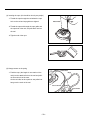
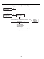
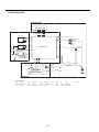
1
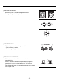
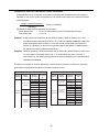
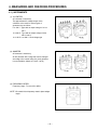
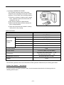
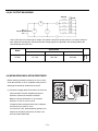
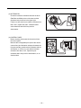
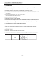
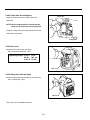
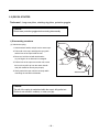
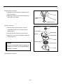
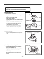
SERVICE
MANUAL
Model
R1700i
GENERATOR
PUB-GS1950
Rev. 09/04
CONTENTS
Section
Title
Page
1. SPECIFICATIONS . . . . . . . . . . . . . . . . . . . . . . . . . . . . . . . . . . . . . . . . . . . . . . . . . . . . . 1
2. GENERAL DESCRIPTION . . . . . . . . . . . . . . . . . . . . . . . . . . . . . . . . . . . . . . . . . . . . . . 2
2-1 EXTERNAL VIEW . . . . . . . . . . . . . . . . . . . . . . . . . . . . . . . . . . . . . . . . . . . . . . . . . . 2
2-2 CONTROL PANEL . . . . . . . . . . . . . . . . . . . . . . . . . . . . . . . . . . . . . . . . . . . . . . . . . 3
2-3 LOCATION OF SERIAL NUMBER AND SPECIFICATION NUMBER . . . . . . . . . . . 6
2-4 GENERATOR ASSEMBLY . . . . . . . . . . . . . . . . . . . . . . . . . . . . . . . . . . . . . . . . . . . 6
3. RANGE OF APPLICATIONS . . . . . . . . . . . . . . . . . . . . . . . . . . . . . . . . . . . . . . . . . . . . . 7
4. MEASURING AND CHECKING PROCEDURES . . . . . . . . . . . . . . . . . . . . . . . . . . . . .10
4-1 INSTRUMENTS . . . . . . . . . . . . . . . . . . . . . . . . . . . . . . . . . . . . . . . . . . . . . . . . . . .10
4-2 AC OUTPUT MEASURING . . . . . . . . . . . . . . . . . . . . . . . . . . . . . . . . . . . . . . . . . . .13
4-3 MEASURING INSULATION RESISTANCE . . . . . . . . . . . . . . . . . . . . . . . . . . . . . . .13
4-4 CHECKING FUNCTIONAL MEMBERS . . . . . . . . . . . . . . . . . . . . . . . . . . . . . . . . .15
5. ASSEMBLY AND DISASSEMBLY . . . . . . . . . . . . . . . . . . . . . . . . . . . . . . . . . . . . . . . . .18
5-1 PRECAUTIONS . . . . . . . . . . . . . . . . . . . . . . . . . . . . . . . . . . . . . . . . . . . . . . . . . . .18
5-2 SPECIAL TOOLS . . . . . . . . . . . . . . . . . . . . . . . . . . . . . . . . . . . . . . . . . . . . . . . . . .18
5-3 DISASSEMBLY PROCEDURES . . . . . . . . . . . . . . . . . . . . . . . . . . . . . . . . . . . . . . .19
5-4 REASSEMBLE PROCEDURES . . . . . . . . . . . . . . . . . . . . . . . . . . . . . . . . . . . . . . .27
5-5 RECOIL STARTER . . . . . . . . . . . . . . . . . . . . . . . . . . . . . . . . . . . . . . . . . . . . . . . . .36
6. TROUBLESHOOTING . . . . . . . . . . . . . . . . . . . . . . . . . . . . . . . . . . . . . . . . . . . . . . . . .42
7. WIRING DIAGRAM . . . . . . . . . . . . . . . . . . . . . . . . . . . . . . . . . . . . . . . . . . . . . . . . . . . .45
The specifications and information included in this manual were in effect at the time of printing.
FUJI HEAVY INDUSTRIES LTD. reserve the right to change the specifications and to make
modifications in the course of technical progress, at anytime without notice.
No parts of this manual may be reproduced without written permission.
1. SPECIFICATIONS
R1700i
MODEL
Inverter
Type
Frequency
Hz
50
50
60
Alternator
Alternating electric current (AC)
Maximum output
kVA
1.65
Rated output
kVA
1.35
Rated voltage
V
Rated amperage
A
230
240
120
13.5
Rated power factor
1.0
Direct Current (DC)
Output
W
100
Voltage
V
12
Power Current
A
8.3
Model
EH09-2D
Type
Forced air-cooled, 4-cycle, OHV Gasoline Engine
Displacement
mL(cc)
85.8
Engine
Fuel
Fuel tank capacity
Automotive Unleaded Gasoline
L
3.5
Rated continuous operation [Approx.]
(at Rated output)
hours
3.5
Oil pan capacity
L
0.36
Ignition System
Digital ignition
NGK BMR4A - NO SUBSTITUTIONS-WILL
NGK BMR4A EFFECT PERFORMANCE
Spark plug
Recoil starter
Starting system
Alternating electric current output
Receptacle (15A x 2)
Direct Current Output
Receptacle (15A x 2) GFCI Receptacle (20A x 2)
Terminal
Over current protector
Equipment
Alternating electric current (AC) output
Electronics Breaker
Circuit Breaker
Direct Current (DC) output
Oil Sensor
Yes
Frequency Switch
Yes
Auto Power Save Switch
Yes
Output Lamp
Yes
Overload Lamp
Yes
Oil Warning Lamp
Yes
Dimension
Length x Width x High
Dry weight kg
mm
490 x 295 x 445
20.5
kg
Specifications are subject to change without notice.
–1–
2. GENERAL DESCRIPTION
2-1) EXTERNAL VIEW
R1700i
RECOIL STARTER (HANDLE)
CONTROL
PANEL
AIR CLEANER
FUEL DRAIN
SCREW
SIDE PANEL (L)
CARRYING HANDLE
TANK CAP COVER
SPARK
PLUG
CAP
OIL GAUGE
(OIL FILLER)
EXHAUST
OUTLET
SIDE PANEL (R)
OIL DRAIN PLUG
–2–
2-2) CONTROL PANEL
R1700i
OIL SENSOR LAMP
OVERLOAD LAMP
AUTO POWER SAVE LAMP
AUTO POWER SAVE SWITCH
PILOT LAMP
AC RECEPTACLES
DC TERMINALS
ENGINE SWITCH
DC CIRCUIT BREAKER
GROUND TERMINAL
(1) ENGINE SWITCH
The engine switch is designed for easy operation with the
interlocking mechanism between the fuel cock and the choke
furnished.
STOP
ENGINE SWITCH
RUN
CHOKE
(CHOKE)
"
"
To start the engine, turn the knob to the position.
(Choke valve is closed.)
Keep the knob in this position after the engine starts.
(The engine can be started with the knob at this position
" (RUN) when the engine is warm.)
" (STOP)
To stop the engine, return the knob to the position.
(The fuel cock is closed as well.)
–3–
(2) PILOT LAMP and OVERLOAD LAMP
① Output lamp
Green light . . . . . Indicates that the generator is generating.
Unlit . . . . . . . . . . . The generator is not generating.
② Overload Lamp
Red light . . . . . . . Indicates when an overload occurs, or
output is abnormal, generating will stop
when the red lamp is displayed.
(The electronics breaker is activated)
NOTE : When the overload lamp is lit, please consult the Troubleshooting section and disconnect any electrical devices.
To reset, turn the engine off and restart it.
(3) OIL SENSOR LAMP
When the level of the engine oil falls below the prescribed value,
the alarm lamp lights up and the engine stops automatically.
When the engine stops due to oil shortage, it can not be started
anymore even by pulling the start knob (just the alarm lamp
flickers). In such a case, replenish engine oil up to the mouth of
the oil filling port.
(4) AUTO POWER SAVE SWITCH
When the switch is in the " " (
) position, the engine speed
will be automatically decreased when an electrical device is
not in use.
Also, when the switch from the electrical device is on, the
electrical load is automatically detected, and the engine speed
will be adjusted according to this load.
● When a large electrical wattage is in use, set the switch to
" "(
) to lower the voltage fluctuation.
● When using a direct current (DC) output to charge a battery,
turn the switch to " " (
).
● When starting the engine with the switch in the "
"(
)
position in the cold weather condition, engine speed will not be
at a low speed for the first several minutes during warm up.
●
–4–
PILOT
LAMP
OVER
LOAD
(5) AC RECEPTACLES
AC electric power is available through this receptacle.
Use a ground type, three-leg plug.
(6) DC TERMINALS
(-)
DC TERMINAL
(+)
DC electric power for battery charge is available.
- Red is positive (+) terminal.
- Black is negative (-) terminal.
DC 12V 8.3A
(7) DC CIRCUIT BREAKER
DC circuit breakers shut off electric current when the current
exceeds its limit.
Check for excessive current consumption. After making sure
everything is in order, push the button to the " ON " position.
Fully dischanged battery of large capacity may cause over-current
in DC output circuit.
–5–
BUTTON
KNOB
IN (ON)
OUT (OFF)
2-3) LOCATION OF SERIAL NUMBER (SER No.),, PRODUCTION NUMBER (PROD No.)
The serial number and production number are located on right side cover of the generator operation panel.
R1700i
Serial number
and Production number
(Label)
NOTE : Please specify these numbers when inquiring about the generator or ordering spare parts.
2-4) GENERATOR ASSEMBLY
ROTOR
REAR COVER
3P
CONNECTOR
STATOR
DIODE RECTIFIER
4P CONNECTOR
–6–
3. RANGE OF APPLICATIONS
Generally, the power rating of an electrical appliance indicates the amount of work that can be done by it.
The electric power required for operating an electrical appliance is not always equal to the output wattage
of the appliance. The electrical appliances generally have a label showing their rated voltage, frequency,
and power consumption (input wattage). The power consumption of an electrical appliance is the power
necessary for using it. When using a generator for operating an electrical appliance, the power factor and
starting wattage must be taken into consideration.
In order to determine the right size generator, it is necessary to add the total wattage of all appliances to
be connected to the unit.
Refer to the followings to calculate the power consumption of each appliance or equipment by its type.
(1) Incandescent lamp, heater, etc. with a power factor of 1.0
Total power consumption must be equal to or less than the rated output of the generator.
Example : A rated 3000W generator can turn thirty 100W incandescent lamps on.
(2) Fluorescent lamps, motor driven tools, light electrical appliances, etc. with a smaller power factor
Select a generator with a rated output equivalent to 1.2 to 2 times of the power consumption of the
load. Generally the starting wattage of motor driven tools and light electrical appliances are 1.2 to 3
times lager than their running wattage.
Example : A rated 250 W electric drill requires a 400 W generator to start it.
NOTE 1: If a power factor correction capacitor is not applied to the fluorescent lamp, the more power
shall be required to drive the lamps.
NOTE 2: Nominal wattage of the fluorscent lamp generally indicates the output wattage of the lamp.
Therefore, if the fluorescent lamp has no special indication as to the power consumption,
efficiency should be taken into account as explained in ltem (5) on the following page.
(3) Mercury lamps with a smaller power factor
Loads for mercury lamps require 2 to 3 times the indicated wattage during start-up.
Example : A 400 W mercury lamp requires 800 W to 1200 W power source to be turned on. A rated
3000 W generator can power two or three 400 W mercury lamps.
(4) Initially loaded motor driven appliances such as water pumps, compressors, etc.
These appliances require large starting wattage which is 3 to 5 times of running wattage.
Example : A rated 900 W compressor requires a 4500 W generator to drive it.
NOTE 1: Motor-driven appliances require the aforementioned generator output only at the starting.
Once their motors are started, the appliances consume about 1.2 to 2 times their rated power
consumption so that the excess power generated by the generator can be used for other
electrical appliances.
NOTE 2: Motor-driven appliances mentioned in items (3) and (4) vary in their required motor starting
power depending on the kind of motor and start-up load. If it is difficult to determine the
optimum generator capacity, select a generator with a larger capacity.
–7–
(4) Appliances without any indication as to power consumption
Some appliances have no indication as to power consumption; but instead the work load (output) is
indicated. In such a case, power consumption is to be worked out according to the numerical formula
mentioned below.
(Output of electrical appliance)
= (Power consumption)
(Efficiency)
Efficiencies of some electrical appliances are as follows :
Single-phase motor . . . . . .0.6 to 0.75 (The smaller the motor, the lower the efficiency)
Fluorescent lamp . . . . . . . .0.7 to 0.8
Example 1: A 40W fluorescent lamp means that its luminous output is 40W. Its efficiency is 0.7 and
accordingly, power consumption will be 40÷0.7= 57W. As explained in Item (2), multiply this
power consumption value of 57W by 1.2 to 2 and you will get the figure of the necessary
capacity of a generator. In other words, a generator with a rated output of 1000W capacity
can light nine to fourteen 40W fluorescent lamps.
Example 2 : Generally speaking, a 400W motor means that its work load is 400W. Efficiency of this motor
is 0.7 and power consumption will be 400÷0.7= 570W. When this motor is used for a
motor-driven tool, the capacity of the generator should be multipled by 1.2 to 3 and 570W as
explained in the ltem (3).
The power consumption of electrical appliances is shown below for reference, use this as a measuring
guide when choosing electrical appliances and which generator to use.
Electrical Appliances
Electrical
appliances
Starting
wattage
One of power
consumption
Electrical
appliances
Power
Consumption
(W)
Rice Cooker
300 to 1000
Coffee Maker
450
Electric grill
800 to 1400
Color TV
100
Hair dryer
Household
Appliances
1.2 to 2 times
of power
consumption
3 to 5 times
of power
consumption
Electrical Appliances
Air conditioner
Electrical
appliances
Starting
wattage
One of power
consumption
1200
1200
Microwave
800 to 1200
Lawn mower
400
Refrigerator
100 to 260
Vacuum cleaner
1100
Washer
500
Air Cooler
600
Deep well pump
600
Mercury lamp
40 to 400
Electrical tools
/Architecture
1.2 to 2 times
of power
consumption
3 to 5 times
of power
consumption
–8–
Electrical
appliances
Power
Consumption
(W)
Soldering iron
300 to 1000
Lighting for
young sardines
600
Drill
350 to 600
Disc Grinder
500 to 1200
Electrical hammer
1000
Chain sow
1200
Impact wrench
1200
Vibrator
800 to 1200
Drill for shiitake
400
Air compressor
1000 to 2600
Winch
1100
water pump
500
NOTES : Wiring between generator and electrical appliances
1. Allowable current of cable
Use a cable with an allowable current that is higher than the rated input current of the load (electrical
appliance). If the input current is higher than the allowable current of the cable used, the cable will
become excessively heated and deteriorate the insulation, possibly burning it out. The table below
shows cables and their allowable currents for your reference.
2. Cable length
If a long cable is used, a voltage drop occurs due to the increased resistance in the conductors
decreasing the input voltage to the load (electrical product). As a result, the load can be damaged.
The table below shows voltage drops per 30 meters of cable.
Cross
sectional
mm2
Allowable
Current
A
Cable
Resistance
Ω/100m
5A
10A
15A
20A
25A
30A
1.25
12
1.486
4.5V
8.9V
*
*
*
*
2.0
17
0.952
2.8V
5.7V
8.6V
*
*
*
3.5
23
0.517
1.6V
3.1V
4.7V
6.2V
*
*
5.5
35
0.332
1.0V
2.0V
3.0V
4.0V
5.0V
6.0V
Voltage drop indicates as V=
Voltage drops per 30 meters of cable
1
xRxIxL
100
R : Resistance (Ω/100m)
I : Electric current (A)
L : Length (m)
The length of wire (L) indicates round length, which is the length from the generator
to the electrical tools and back.
<Example>
R : Resistance 1.25mm2=1.48Ω/100m
I : Electric current 10A
L : Length 30m
The voltage drop of the case described above
V= 1.48Ω x 10A x (30m x 2) ≒ 8.9 (V)
100
–9–
4. MEASURING AND CHECKING PROCEDURES
4-1) INSTRUMENTS
(1) VOLTMETER
AC voltmeter is necessary.
The approximate AC voltage ranges of the
voltmeters to be used for various types of
generators are as follows :
0 to 150 V : Type with an output voltage of 110 or
120 V
0 to 300 V : Type with an output voltage of 220,
230 or 240 V
0 to 150 V, 0 to 330 V : Dual voltage type
For AC
For DC
For AC
For DC
(2) AMMETER
AC ammeter is necessary.
An AC ammeter with a range that can be changed
according to the current rating of a given generator
is most desirable. (About 10 A, 20 A, 100 A)
(3) FREQUENCY METER
Frequency range : To cover 45 to 65Hz
NOTE : Be careful of the frequency meter's input voltage
range.
– 10 –
(4) CIRCUIT TESTER
For measuring resistance, etc.
NOTE : The ordinary circuit tester may cause erroneous
readings due to their measuring method.
Use a high-grade, precise circuit tester to check
the generator components.
(5) MEAGER TESTER
Used for measuring generator insulation resistance.
Select the one with testing voltage range of 500V.
(6) TACHOMETER
Use the contactless type tacho meter for checking
engine speed.
– 11 –
(7) "Dr.Robin" GENERATOR TESTER
The "Dr.Robin" generator tester is exclusively
designed for fast, easy diagnosis and repair of Robin
generators. The "Dr.Robin" has the following features :
1) Functions of voltmeter, frequency meter, megger
tester, capacitance meter and circuit tester are
combined in one unit.
2) Fast and easy readout by digital indicator.
3) Built-in automatic battery checker indicates the
time to change batteries.
4) Tester and accessories are installed in a handy,
sturdy case for easy carrying.
SPECIFICATIONS
MODEL
Dr.Robin
Part Number
388-47565-08
0 to 500 V AC
Voltage
Measuring
Range
Frequency
25 to 70 Hz
Resistance
0.1 to 1,999 Ω
Condenser Capacity
10 to 100 μF
Insulation Resistance
3MΩ
Fuse
Circuit Protector
2 x 6F44P (006P) Dry Cell Battery
Power Source
Test leads with needle probes ... 1 set
Test leads with jack plugs ... 1 set
Accessories
285 mm x 200 mm x 110 mm
Dimensions (L x W x H)
1.6 kg
Weight
The "Dr.Robin" generator tester can be ordered from Robin generator distributors by the following part number.
Dr.Robin_Part_Number_:_388-47565-08
If you do not have a "Dr.Robin" generator tester, use the instruments described in the following section for
checking generator parts.
– 12 –
4-2) AC OUTPUT MEASURING
SWITCH
LOAD
A
~
V
~
F
TO AC RECEPTACLE
Use a circuit above for measuring AC output. A hot plate or lamp with a power factor of 1.0 may be used as a
load. Adjust the load and rpm, and check that the voltage range is as specified in the following table at the
rated amperage and rated rpm.
R1700i
Specification
120V / 60Hz
230V / 50Hz
240V / 50Hz
117-126
225-242
235-252
4-3) MEASURING INSULATION RESISTANCE
Before checking insulation resistance, be sure to shortcircuit the terminals of an AC receptacle using a wire to
discharge the electricity remained in the circuit.
(1) Connect the megger tester across either one of the two
output terminals of the AC receptacle and ground
terminal to measure the insulation resistance.
Measure it with the AC breaker on. An insulation
resistance of 1 MΩor more is normal.
(Original insulation resistance at the time of shipment
from the factory is 10 MΩor more.)
If it is less than 1 MΩ, disassemble the generator and
measure the insulation resistance of the stator, rotor
and control panel individually.
– 13 –
Voltage
range
Model
(2) ALTERNATOR
Check the insulation resistance between the three
(Red,Blue and White) wires of the stator and the
generator body as shown in the figure right.
If there is a wire which has insulation resistance less
than 1 MΩ, replace the stator. Insulation failure
cause electrical leak which may result in
electrocution.
(3) CONTROL PANEL
Before checking, disconnect the inverter unit from
the control panel.
Measure the rechargeable parts (where the electric
current flows) and insulation resistance between the
live parts and the ground terminal. Measure with the
AC breaker on. If there is a spot where insulation
resistance less than 1 MΩ, replace the part.
Insulation failure may result in electrification, or an
electrical leak.
– 14 –
4-4) CHECKING FUNCTIONAL MEMBERS
(1)STATOR
Measure the winding wire resistance. Check the
resistance of the wires that comes out from the
stator using a tester, referring to the following table.
NOTE: When measuring according the numerical value
shown in the chart, tolerance should be
considered because the inaccuracy of the tester.
If an accurate value is needed, measure by
electric resistance using an Ohm-meter.
While doing this, use caution to avoid contact
resistance.
Generator wire resistance
Unit;Ω
AC 120V
AC 230V
AC 240V
Specification Specification Specification
Color of the wires
4P Connector (AC output line)
Diode Rectifier Connector
Red-Blue
1.2
4.2
4.2
Blue-White
1.2
4.2
4.2
White-Red
1.2
4.2
4.2
Yellow-Yellow/Blue
0.2
2.1
2.1
(2)INVERTER UNIT
Check if there is no color change or blister on the
filling resin, and confirm that there is no damage or
color change in the electrical parts, electrical wires,
or the connectors.
And, check the resistance at the 2P connector for
AC output and at the 4P connecter for the stator
wire terminals.
White
a
c
b
d
Red
Stator wire
terminal
Stator wire Terminal
2P connector
for AC output
2P Connector for AC output
Apply black needle
of the circuit tester
Apply red needle of the circuit tester
Red
White
a
b
c
d
Red
ーーー
0.57 kΩ
a
ーーー
5 MΩ∼
4 MΩ∼
4 MΩ∼
White
0.57 kΩ
ーーー
b
2.5 MΩ∼
ーーー
10 MΩ∼
10 MΩ∼
c
2.5 MΩ∼
10 MΩ∼
ーーー
10 MΩ∼
d
2.5 MΩ∼
10 MΩ∼
10 MΩ∼
ーーー
– 15 –
(3) DIODE RECTIFIER
The internal circuit of the diode rectifier is shown in the figure below.
Check the continuity between each terminal using a circuit tester.
If the continuity is as charted below, the diode rectifier is normal.
Yellow
Gray
Orange
Diode rectifier
Yellow / Blue
Circuit Tester
Checking table for analogue circuit tester
Apply black (-) needle of the circuit tester
Analogue Circuit Tester
Yellow
Yellow
Apply red (+) needle
of the circuit tester
−
Yellow / Blue
Orange
Gray
No continuity ∞
No continuity ∞
0Ω
Yellow / Blue
No continuity ∞
−
No continuity ∞
0Ω
Orange
0Ω
0Ω
−
0Ω
Gray
No continuity ∞
No continuity ∞
No continuity ∞
−
Checking table for digital circuit tester
Apply red (+)needle of the circuit tester
Digital Circuit Tester
Yellow
Yellow
Apply black (-) needle
of the circuit tester
−
Yellow / Blue
Orange
Gray
No continuity ∞
No continuity ∞
0Ω
Yellow / Blue
No continuity ∞
−
No continuity ∞
0Ω
Orange
0Ω
0Ω
−
0Ω
Gray
No continuity ∞
No continuity ∞
No continuity ∞
−
– 16 –
(4) RECEPTACLE, AC PLUG
Check burn marks in the areas where electric current flows, such as wire and plastic parts of AC receptacle.
(5) OIL SENSOR
Confirm that there is a sufficient amount of
oil.Measure continuity between the wires of oil
sensor and the crankcase using a circuit tester.
Oil Sensor
Ω
Below the lower level : ON (continuity)
0Ω
Above the lower level : OFF(non-continuity) ∞
Use 4-stroke automotive detergent oil of API service
class SE or higher Grade (SG, SH or SJ is
recommended).
Oil capacity : 0.4 liters
– 17 –
5. ASSEMBLY AND DISASSEMBLY
5-1) PRECAUTIONS
(1) Be sure to memorize the location of each part when disassembling the generator so that the generator can be
correctly reassembled. Tag the disassembled parts with the necessary information to facilitate easier and
smoother reassembling.
(2) For greater convenience, divide the parts into several groups and store them in boxes.
(3) To prevent bolts and nuts from being misplaced or installed incorrectly, place them temporarily back at their
original position.
(4) Handle disassembled parts with care; wash them with clean oil.
(Do not clean electrical parts with oil nor water.)
(5) Remove battery before disassembly.
(6) Use proper tools correctly for each specific job.
(7) Please be sure to glue the sponge inside the cover. Please replace the sponge if it is deformed, peeled, or
damaged, with a new one. The generator performance may be negatively affected by the lack of a sponge or
deformed, peeled or damaged sponge.
(8) Tie the electric wires and fuel pipe with wire bands as necessary.
※Please refer to Robin Engine Service Manual EH09 for the assembly and disassembly of the engine.
5-2) SPECIAL TOOLS
Use the proper, specialized tools for disassembly and assembly.
By using the proper, specialized tools, maintenance trouble and damage of the equipment can be avoided.
Parts No.
Name of the tool
Available
on market
Puller
Form
Use method
Use to disassemble
flywheel
– 18 –
5-3) DISASSEMBLY PROCEDURES
Please disassemble in the order of the procedure below.
5-3-1 Remove the side panels (Left, Right)
Remove the side panels.
M6 x 16.5mm Bolt : 2 pcs.
Tools : Screw driver
Side Panel
5-3-2 Remove the rear cover
Remove the rear cover by unscrewing the four screws.
M6 x 20mm Screw and Washer : 4pcs.
Tools : Screw driver
Rear cover
5-3-3 Remove rolling wire, choke wire
Choke wire
Loosen the screw that holds the choke wire.
And remove it from the swivel.
Unwind the rolling wire by hand or pliers, and pull up.
Tools : Screw driver, pliers
Rolling wire
– 19 –
5-3-4 Remove the recoil starter handle
Remove the recoil starter guide connected to the case
body (left).
Push the guide and the starter hundle through the hole
which the case body (left) guide was attached.
M4 x 10mm Tapping screw : 1pce.
Recoil starter
hundle
Tools : Screw driver
Guide
Overflow pipe
5-3-5 Remove the control panel (1)
Case body
Remove the control panel from the case body.
Control Panel
M4 x 14mm Screw : 4pcs.
M5 x 8mm Screw : 4pcs.
Tools : Screw driver
NOTE: At this point, the couplers of electrical wires are
connected to the control panel. Instead of
removing the control panel forcibly, remove it
after disassembling the case body and fuel tank.
5-3-6 Remove the case body (Left, Right)
Case body
Remove the case body (Left, Right)
Remove the plastic pipe from the case body.
(Overflow pipe)
Upper part of the case body
M6 x 25mm Screw and Washer : 2pcs.
M6 x 20mm Screw and Washer : 1pce.
M4 x 110mm Screw : 1pce.
Tools : Screw driver
Bottom part of the case body
Remove the case with the mount still fastened to it.
M6 x 18mm Flange bolt : 4pcs.
Tools : 10mm Box wrench
Mount
– 20 –
5-3-7 Remove rear frame
Front
frame
Remove the rear frame.
Rear frame
5-3-8 Remove fuel cock bracket
Fuel pump
Remove the fuel cock bracket.
M6 x 12mm Flange bolt : 1pce.
M6 Nut : 1pce.
Tools : 10mm Box wrench
NOTE 1: Be sure to close the fuel cock before removing
the fuel pipe.
(Engine switch in the off position)
NOTE 2: A little fuel comes out from the fuel pump when
unplug the pipe.
Unplug the pipe
Fuel cock bracket
5-3-9 Remove the fuel tank
Remove the fuel tank with the fuel cock still connected.
– 21 –
Fuel tank
5-3-10 Remove the control panel (2)
Remove the control panel by pulling off the three couplers.
Remove the choke wire bracket from the front frame.
Couplers
5-3-11 Remove the inverter unit
Choke wire
bracket
Disconnect the two couplers and remove the inverter
unit.
(one coupler from the alternator body, and one from the
engine throttle / ignition system.)
Inverter Unit
M6 x 20mm Flange bolt : 4pcs.
Tools : 10mm Box wrench
5-3-12 Remove the fuel pipes
Fuel pipe
(Carburetor side)
Remove the fuel pipe from the fuel pump to carburetor
and the fuel pipe on crank case side.
Tools : Pliers
Fuel pipe
(Crank case side)
– 22 –
5-3-13 Remove the air cleaner and carburetor
Air Cleaner
Unhook the catch on the right side of the air cleaner.
Then remove the air cleaner cover and elements.
Loosen the two nuts and bolt to remove the base plate of
the air cleaner.
Carburetor
Then remove the carburetor.
M6 x 18mm Flange bolt : 1pce.
M6 Flange nut : 2pcs.
Base plate
Tools :10mm Box wrench
5-3-14 Remove the front frame
Front frame
Remove the front frame.
5-3-15 Remove the base inverter
Remove the base inverter.
M6 nut : 4 pcs, also
M8 x 16 Bolt and washer : 4pcs.
Tools : 12mm Box wrench
Base inverter
– 23 –
5-3-16 Remove the Stator / Rear cover
Remove the Stator / Rear cover.
Rear cover
M6 x 25mm Flange bolt : 3pcs.
Tools : 10mm Box wrench
NOTE 1: The stator is attached to the rear cover, both
can be removed together.
They are attached with a strong magnetic force,
so pull out straight.
Rear cover
<CAUTION>
The stator and the rotor are pulling each other by a
strong magnetic force. Please use caution when
removing the stator in order to prevent from getting
injury on fingers.
Stator
5-3-17 Remove the rotor
Rotor
Remove the rotor.
M6 x 20mm Flange bolt : 3pcs.
Tools : 10mm Box wrench
NOTE : There is a strong magnetic field around the rotor.
Use atmost care to avoid foreign substances
such as small iron particles stick to the rotor.
– 24 –
5-3-18 Remove Blower housing
Remove the blower housing.
Blower
Housing
M8 x 55mm Flange bolt : 1pce.
M8 x 90mm Flange bolt : 3pcs.
Tools : 12mm Box wrench
NOTE : The pipe knock is attached to two places.
5-3-19 Remove the flywheel
Remove the flywheel.
Flywheel
M8 x 20 Bolt and washer : 1pce.
NOTE: Use a Flywheel puller (Available on market) for
the taper.
Tools : 12mm Box wrench
Flywheel puller (Available on market)
5-3-20 Remove recoil starter
Remove the recoil starter.
M6 x 20mm AY Bolt : 3pcs.
Tools : 10mm Box wrench
NOTE: For the maintenance of recoil starter, please refer
to item "5-5) Disassembly and assembly of the
recoil starter".
– 25 –
Recoil starter
5-3-21 Remove the muffler
Remove the muffler.
M8 x 80mm Flange bolt : 1pce.
M6 Flange nut : 2pcs.
Tools : 10mm Box wrench
12mm Box wrench
Muffler
5-3-22 Remove the ignition coil
Remove the ignition coil.
M6 x 14mm Flange bolt : 1pce.
M8 Flange nut : 1pce.
Ignition coil
Tools : 10mm Box wrench
12mm Box wrench
5-3-23 Remove the cylinder baffle
Remove the cylinder baffle.
Cylinder baffle
M8 x 16mm Flange bolt : 3pcs.
M6 x 12mm Flange bolt : 1pce.
Tools : 10mm Box wrench
12mm Box wrench
By performing the above steps, only a bare engine remains.
Please refer to EH09 Service manual for further disassembly and service procedures of the engine.
– 26 –
5-4) REASSEMBLY PROCEDURES
5-4-1 Cylinder baffle
Install the cylinder baffle. (Tighten together)
M8 x 16mm Flange bolt : 3pcs.
Cylinder baffle
Tightening torque : 11.0-13.0 N・m
110-130 kgf・cm
ft・lbs)
(8.1-9.6
M6 x 12mm Flange bolt : 1pce.
Tightening torque : 7.0-9.0
70-90
(5.2-6.6
N・m
kgf・cm
ft・lbs)
5-4-2 Ignition coil
Install the ignition coil into the ignition coil bracket and
attach it to the engine.
Ignition coil tightening torque
Tightening torque : 3.0-5.0
30-50
(2.2-3.7
Ignition coil
N・m
kgf・cm
ft・lbs)
Ignition coil bracket tightening torque
M6 x 14mm Flange bolt : 1pce.
Tightening torque : 7.0-9.0
70-90
(5.2-6.6
N・m
kgf・cm
ft・lbs)
M8 Flange nut : 1pce.
Tightening torque : 11.0-13.0 N・m
110-130 kgf・cm
ft・lbs)
(8.1-9.6
5-4-3 Muffler
Install the muffler.
M8 x 80mm Flange bolt : 1pce.
Tightening torque : 11.0-13.0 N・m
110-130 kgf・cm
ft・lbs)
(8.1-9.6
Muffler
M6 Flange nut : 2pcs.
Tightening torque : 7.0-9.0
70-90
(5.2-6.6
N・m
kgf・cm
ft・lbs)
– 27 –
5-4-4 Recoil starter
Attach the recoil starter to the crankcase.
M6 x 18mm Flange bolt : 3pcs.
Tightening torque : 7.0-9.0
70-90
(5.2-6.6
N・m
kgf・cm
ft・lbs)
Recoil starter
5-4-5 Flywheel
Install the flywheel.
M8 x 25 Bolt and washer : 1pce.
8.5D x 28D x 3.2T Washer : 1pce.
Tightening torque : 19.0-21.0 N・m
190-210 kgf・cm
(14.0-15.5 ft・lbs)
NOTE : Wipe off any oil from the tapered shaft and hole
before assembling.
Flywheel
5-4-6 Air gap adjustment of flywheel and pulsar
coil
Pulsar
coil
Adjust the air gap between flywheel and pulsar coil to
0.5mm with a feeler gauge. Attach the pulsar coil to the
engine.
Air gap : 0.5 mm
Flywheel
– 28 –
5-4-7 Pulsar coil and grommet
Recoil guide
Tighten the bolt in place, making adjustments according
to 5-4-6.
M6 x 8mm Flange bolt : 2pcs.
Tightening torque : 3.0-5.0
30-50
(2.2-3.7
Flywheel
Pulsar coil
Grommet
N・m
kgf・cm
ft・lbs)
Place the pulsar coil wires along the groove of the
grommet and recoil guide to make it easier to assemble
the blower housing.
Pulsar coil harness
Caution : Do not forget to put the 2 pieces of pipe knock.
5-4-8 Blower housing
Install the blower housing
M8 x 55mm Flange bolt : 1pce.
M8 x 90mm Flange bolt : 3pcs.
Blower
housing
Tightening torque : 18.0-20.0 N・m
180-200 kgf・cm
(13.3-14.8 ft・lbs)
NOTE: Insert the grommet (pulsar coil harness) and
recoil guide into the blower housing securely.
– 29 –
5-4-9 Rotor
Rotor
Install the rotor.
M6 x 20mm Flange bolt : 3pcs.
Tightening torque : 10.0-12.0 N・m
100-120 kgf・cm
(7.4-8.9 ft・lbs)
<CAUTION>
The stator and the rotor are pulling each other by a
strong magnetic force. Please use care when
assembling the stator close to the rotor.
Carelessness may cause injury such as smashing a
finger.
Rotor
NOTE : Avoid damaging the magnet of the rotor.
5-4-10 Rear cover, stator
Rear cover
Install the rear cover of the generator and stator into the
rotor.
NOTE: The rotor and the stator are pulling each
other by a very strong magnetic force.
Make sure the rotor does not have foreign
substances on it, and fingers are not
smashed when installing.
Stator
Install the rear cover to the blower housing.
M6 x 25mm Flange bolt : 3pcs.
Rear cover
Tightening torque : 10.0-11.0 N・m
100-110 kgf・cm
(7.4-8.1 ft・lbs)
NOTE: Make sure of the direction of rear cover
during installation.
– 30 –
5-4-11 Base Inverter
Install the base inverter into the engine main body.
M8 x 20 Bolt and washer : 4pcs.
Tightening torque : 18.0-20.0 N・m
180-200 kgf・cm
(13.3-14.8 ft・lbs)
M6 Flange nut : 4pcs.
Tightening torque : 9.0-11.0
90-110
(6.6-8.1
N・m
kgf・cm
ft・lbs)
Base inverter
NOTE: Avoid cutting your hand by the sharp edge of
the base.
Front frame
5-4-12 Front frame
Install the front frame (L) and (R) onto the base inverter.
5-4-13 Air cleaner bottom plate and carburetor
Install the insulator,gaskets, carburetor, baffle stay, and
air cleaner base plate into the cylinder head.
Carburetor
M6 Flange nut : 2pcs.
Tightening torque : 7.0-9.0
70-90
(5.2-6.6
N・m
kgf・cm
ft・lbs)
Air cleaner
base plate
NOTE: Please do not forget to install the gasket.
Air cleaner
5-4-14 Air cleaner
Install the element and air cleaner cover onto the air
cleaner base plate.
M6 x 18mm Flange bolt : 1pce.
– 31 –
5-4-15 Fuel pipe
Fuel pipe
(Carburetor side)
Connect the fuel pipes from the fuel pump to the
crankcase and carburetor and fasten with a hose clamp.
NOTE: Assemble with care.
Avoid mis-connection of fuel pipes.
Fuel pipe
(Crank case side)
5-4-16 Inverter unit
Attach the inverter unit into the front frame.
A grounding wire shall be tightened together to the upper
right side of the inverter unit.
M6 x 20mm Flange bolt : 4pcs.
Inverter
unit
Tightening torque : 3.0-4.0 N・m
kgf・cm
30-40
(2.2-2.9 ft・lbs)
5-4-17 Installing coupler
Connect the harness of the control panel, and inverter unit.
Be sure to securely fasten the couplers of the harness
before installing the control panel.
Couplers
NOTE: When fastening, make sure there are no
mis-wiring of harness, or forgotten wiring.
– 32 –
5-4-18 Fuel tank
Fuel tank
Attach the fuel tank and the fuel cock.
After the fuel tank is installed, connect the fuel line
between fuel cock and fuel pump.
5-4-19 Fuel cock bracket
Fuel cock
bracket
Install the fuel cock bracket into the base.
(Install the rubber pipe with the hose clamp
while the fuel cock is closed.)
M6 x 12mm Flange bolt : 1pce.
M6 Nut : 1pce.
Mounting
angle
Tightening torque : 3.0-4.0 N・m
kgf・cm
30-40
(2.2-2.9 ft・lbs)
Base
surface
5-4-20 Rear frame
Front
frame
Attach the rear frame (L) and (R) to the base inverter.
Rear frame
– 33 –
5-4-21 Case body, control panel
Case body
Attach the case body (left and right). Install the bottom
part of the case body and the mount together.
M6 x 18mm Flange bolt : 4pcs.
Tightening torque : 3.0-4.0 N・m
kgf・cm
30-40
(2.2-2.9 ft・lbs)
NOTE: Install the bottom part of the case body
correctly.
Mount
Attach the upper part of the case body.
M6 x 25 Screw and Washer : 2pcs.
Case body
Control panel
Tightening torque : 3.0-4.0 N・m
kgf・cm
30-40
(2.2-2.9 ft・lbs)
NOTE: Avoid gaps in the upper part of the case body
when installing.
Install the control panel into the case body.
M4 x 14mm Screw : 4pcs.
M5 x 8mm Screw : 4pcs.
Tightening torque : 2.0-3.0 N・m
20-30
kgf・cm
(1.5-2.2 ft・lbs)
5-4-22 Recoil starter and guide
Install the guide of the starter hundle.
Install the guide and starter hundle after they are
pushed through the mounting hole from inside of the
case body.
M4 x 10mm Tapping screw : 1pcs.
Insert the overflow pipe through the hole in the bottom
of the case body.
Recoil starter
hundle
Guide
Overflow pipe
– 34 –
5-4-23 Choke wire and rolling wire
Choke wire
Install the choke wire into the choke shaft of the
carburetor.
NOTE: Use the engine switch to confirm that the
choke can be fully closed, and fully opened.
Install the rolling wire into the wire plate and fuel cock
behind the control panel.
Rolling wire
5-4-24 Rear cover
Attach the rear cover to the case body.
M6 x 30 Screw and Washer : 4pcs.
Tightening torque : 3.0-4.0 N・m
kgf・cm
30-40
(2.2-2.9 ft・lbs)
Rear cover
5-4-25 Side panels (left and right)
Attach the side panel (left and right) to the case body.
M6 x 16.5mm Bolt : 2pcs.
Side Panel
This is the end of assembly procedures.
– 35 –
5-5) RECOIL STARTER
Tools used : Long-nose pliers, retaining-ring pliers, protective goggles
Caution :
Please wear protective goggles before starting disassembly
1) Disassembly procedures
(1) Unhook the spring.
-1 Hold the starter handle, and pull out the starter rope.
-2 Pull out all of the rope, and align the rope guide
and the knot of the rope inside the reel.
Starter rope
-3 Be sure to hold the reel with both thumbs
so your fingers do not become be entangled.
-4 Pull the knot of the rope out from the reel, loosen
the knot, then pull it up from the starter handle
side (this should be done by two people).
-5 Slowly rewind the rope until the reel stops while
controlling the reel with both thumbs.
Caution :
The pull of the spring is maximized while the rope is fully pulled out.
Please do not release it suddenly, or relax your grip.
– 36 –
Starter handle
(2) Remove the small parts.
-1 Hold the case, and remove the retaining-ring C
with the ring pliers.
-2 Beginning at the top, remove the retaining-ring,
friction plate, and ratchet.
Retaining-ring
pliers
Retaining-ring C
(3) Remove the reel.
Retaining-ring C
-1 Move the reel to left and right at a 1/4 turns
Friction plate
several times until it moves smoothly, gently
Friction spring
holding it down.
Ratchet guide
-2 Slowly lift the reel, removing it from the case.
Ratchet
-3 Repeat (3) 1 and (3) 2 if the spring assembled in
Return spring
the reel sticks out.
Reel
Retaining-ring E
Spiral spring
Caution :
The reel is disassembled with the spring still
assembled, so place it on a flat table without
dropping, or shaking.
Disassembly is completed.
– 37 –
Case
Caution:
Please wear protective goggles before starting assembly.
2) Assembly procedure
(1) Assemble the reel into the case.
Ratchet
-1 Install the ratchet, and fasten it with retaining
ring E.
-2 Install the spiral spring in the reel.
Reel
-3 Apply grease to the case.
-4 Properly orient the inner end of the spring installed
Retaining-ring E
in the reel.
Spiral spring
-5 Hold the reel so that the shaft and hook part can
be caught on the inner end of the spring, and
softly drop into the case from the top.
-6 Move the reel gently in the counter-clockwise
Case
direction, making sure that the spring catches.
Grease
(2) Install the small parts.
-1 Install the ratchet guide and return spring into the
Ratchet guide
Return spring
reel.
(3) Installing friction plate, retaining ring C
Friction plate
-1 Install by putting the friction spring end into the
spring part of the ratchet guide.
Align the cut of the friction plate to the cut of the
recoil starter main body, and fasten with the
retaining ring C.
Be sure that the retaining ring is fitted into the
Retaining ring C
grooves.
Friction spring
– 38 –
(4) Inserting the rope. (this should be done by two people)
-1 Thread the rope through the reel where the rope
hole on the reel and rope guide are aligned.
About 20cm
-2 Thread the rope end through the rope guide and
the rope hole of the reel, and pull 20cm out from
the reel.
-3 Tight the end of the rope.
Ab
ou
t1
0m
m
(5) Keep pressure on the spring
-1 Feed the rope .(the length of one rotation of the
Fixed hole
Rope
reel) from the attached hole of the reel and pull it
out from teh hole of the case.
On the reel side, let the rope that was pulled out
hang over the notch of the reel.
Cut of the reel
Pull off hole
– 39 –
-2 Wind the rope clockwise seven times with the rope
hanging from the reel.
Gently wind the rope onto the reel while
removing any kinks in the rope from the knob side.
Rope
Assembly is completed.
Cut of the reel
Wind up for
seven times
clockwise
※These are the disassembly and assembly procedures, please be sure to review the following item checklist to
insure that the parts securely installed.
3) Checking items after assembly
(1) Try to pull the starter handle for 2 to 3 times.
(a)When the starter handle is difficult to pull, please make sure the parts, etc., are installed in the right direction.
(b)When the ratchet does not operate, please re-check if there are any missing parts such as the spring.
(2) Pull the starter handle and try to pull the starter rope out to the limit.
(a)When the starter rope remains in the rope groove of the reel, pressure is put on the spring. Pull out 30cm of
the starter rope, holding the reel firmly with your thumb, and then pull the starter rope out towards of the
recoil starter. Next, rewind it 1~2 times, controlling reel rotation.
(b)When the starter rope does not return smoothly, or the starter handle is hangs down loosely, please add
grease or mobile oil in the rotating and friction parts.
If it still does not work, rewind 1~2 times.
(In that case, confirm that the spring is not under pressure by following the previous procedure.)
(c)Please re-assemble from the beginning if there was the sound when the spring was removed and the starter
rope does not re-winded into the reel.
– 40 –
4) When . . .
(1)The spring pops out
(a)Hook the end hook of the spring to the notched
part of the reel, and attach the spring, applying
pressure with your fingers so that it isn’t released
from the groove. (Please wear gloves)
(b)Hook the inside hook of the spring to the claw of
the starter case while turning.
※ Please refer to assembly procedures.
(2) Oil refill
At the end of the season or when disassembling, add
grease (preferably one that is heat resistant, if
possible) or mobile oil to rotation parts, friction parts,
and the spring.
– 41 –
Spiral spring
Reel
6.TROUBLESHOOTING
No output power or Lower output
Turned on
When engine is running,
check if Overload Lamp is activated
Remove any electric load
equipment that is connected
※Once stop the engine, and reset the overload warning
Turned off
When engine is running,
check if the Pilot Lamp is turned on
Voltage
exceeds
rated range
Confirm the engine revolutions
(turn the APS sw to OFF)
correct revolution 4100∼4300rpm
Turned off
Within the rating
Low, High
Go to the "Engine does
not start (Start failure)"
(refer to p. 44)
Measured resistance value
Red
White
Blue
Generator
Measured resistance value between
Red-white
White-blue
Red-blue
)
(Refer to the figure below)
Abnormal
Change the generator
Change INV C/U
<Resistance value of the generating main body for reference>
Unit : Ω
Red - Blue
Blue - White White - Red
AC120V
1.2
1.2
1.2
AC230V/240V
4.2
4.2
4.2
Surrounding temperature 20℃
– 42 –
Improper revolutions (Electronic throttle)
Starts but
stops suddenly
Yes
Go to the "Engine does not start (Start failure)"
No
・Engine revolution
does not increase
・Hunting
Yes
Confirm connection of
electronic throttle part
OK
・Pull the recoil lightly with the carburetor throttle fully opened
Does
not run
Full throttle direction :Towards the opposite direction against the
air cleaner in front.
Runs
・Dirty or bad spark plug
・Poor return of the choke
・Air cleaner blockage
・Muffler blockage
・Bad carburetor (water leak-in, blockage, etc.)
・Lack of gasoline
・Gasoline corrosion
・Blockage from the tank to the carburetor
– 43 –
Change the
stepping motor
or carburetor
Engine does not start (Start failure)
None
Check the gasoline
in the tank
Yes
warning
lamp is on
Oil warning lamp turns on
when the recoil is pulled
Fuel cock is in
the ON position
Add gasoline
NO
Open
the cock
Check the
oil volume
Add oil (up to the
rated volume)
Confirm of the oil SW
E/g
Resistance
value≒0Ω
Change Oil SW
Yes
Gasoline leaks when the
carburetor drain is loosened
NO
Yes
Check for
gasoline corrosion
GND
Clean,
change
the filter
Corrosion
Change
gasoline
Tester
Change the Inverter unit
OK
Remove the spark plug*
and check the electrode
Dry
Blockage of the fuel tube
carburetor, such as noise, etc.
No spark
・Check for dirty plugs, or gap
・Check the connection
(coupler, high tension cord)
Wet
Attach the plug to the plug
cap, and check for sparks
by grounding the electrode
Check the
ignition coil
Sparks
Check the valve clearance
of the compressed pressure
(compression)
NG
Adjustment
Check the
pulsar coil
OK
Change
the unit
Spark Plug - BMR4A (NGK)
* NO SUBSTITUTIONS - WILL EFFECT
PERFORMANCE OR OPERATION.
– 44 –
7. WIRING DIAGRAM
R1700i (50Hz-230V)
CONTROL PANEL
Y
R
Pur
Blu
Grn
Brn
ENGINE
Org
LED INDICATOR
Step motor
R
Grn
Blu
Pur
Gry
AC receptacle
(230V)
W
Ignition coil
SPARK PLUG
Blu
W
Blk
INV&E/G C/U
Auto power
save switch
Brn
Blk
REV Sensor
Y
Grn/Y
R
Blk
Y
W
R
Blu
Float switch
Blk
DC curcuit
breaker
Main coil
Gry
Org
Blk
Engine switch
Brn/W
DC coil
GENERATOR
Wiring color cord
Blk
: Black
Blk/W : Black/White
Blu
: Blue
LBlu : Light blue
Brn
: Brown
Brn/W : Brown/White
Grn
: Green
Grn/W : Green/White
Org
: Orange
– 45 –
Gry : Gray
R
: Red
W : White
Y
: Yellow
W/Blk : White/Black
Grn/Y : Green/Yellow
Pur
: Purple
R1700i (50Hz-240V)
CONTROL PANEL
Y
R
Pur
Blu
Grn
Brn
ENGINE
Org
LED INDICATOR
Step motor
R
Grn
Blu
Pur
Gry
AC receptacle
(240V)
W
Ignition coil
SPARK PLUG
Blu
W
Blk
INV&E/G C/U
Auto power
save switch
Brn
Blk
REV Sensor
Y
Grn/Y
R
Blk
Y
W
R
Blu
Float switch
Blk
DC curcuit
breaker
Main coil
Gry
Org
Blk
Engine switch
Brn/W
DC coil
GENERATOR
Wiring color cord
Blk
: Black
Blk/W : Black/White
Blu
: Blue
LBlu : Light blue
Brn
: Brown
Brn/W : Brown/White
Grn
: Green
Grn/W : Green/White
Org
: Orange
– 46 –
Gry : Gray
R
: Red
W : White
Y
: Yellow
W/Blk : White/Black
Grn/Y : Green/Yellow
Pur
: Purple
R1700i (60Hz-120V)
CONTROL PANEL
Y
R
Pur
Blu
Grn
Brn
ENGINE
Org
LED INDICATOR
Step motor
R
Grn
Blu
Pur
Gry
AC receptacle
(120V)
W
Ignition coil
SPARK PLUG
Blu
W
Blk
INV&E/G C/U
Auto power
save switch
Brn
Blk
REV Sensor
Y
Grn/Y
R
Blk
Y
Blk
W
R
Blu
Float switch
Blk
DC curcuit
breaker
Main coil
Gry
Org
Blk
Engine switch
Brn/W
DC coil
GENERATOR
Wiring color cord
Blk
: Black
Blk/W : Black/White
Blu
: Blue
LBlu : Light blue
Brn
: Brown
Brn/W : Brown/White
Grn
: Green
Grn/W : Green/White
Org
: Orange
– 47 –
Gry : Gray
R
: Red
W : White
Y
: Yellow
W/Blk : White/Black
Grn/Y : Green/Yellow
Pur
: Purple
940 Lively Blvd. • Wood Dale, IL 60191 • Phone: 630-350-8200 • Fax: 630-350-8212
e-mail: [email protected] • www.robinamerica.com
© Copyright 2004 Robin America, Inc.
PRINTED IN THE USA