1
SEIMM MOTO GUZZI
S.
p.
A . . Mand8110 d81 larlo
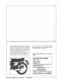
Moto Guzzi V1000 G5 Owner’s Manual
R8gletro Sool"l& Lecco N. 2220
Front and Back Cover
reM,-
The lIIult,etlons end desc,lptions In thIs booklet I,e IndicIUve only In<I th e menulsclu,e,
yes Itlel! the ,Ight to Introduce Iny modUl clUon It mlY deem neceNl". lor beHe, performl nce
0' lor constructive or comme,cli l ,elsonl without prio , nollce_
SEIMM MOTO GUZZI - Technical publications _ Code n. 1890
Printed in Italy _ MarIani - Atmll (Bergamo)
oot - 1000 - 3/78
First of all we wish to thank you for choosing a Mota Guzzi motorcycle.
By following the instructions outlined in this booklet you wi/( ensure
a
long and troublelree life for your machine.
Before riding, please read carefully these instructions in order that you
may know your motorcycle features and how to operate it safely.
All major checking and overhauling jobs are best carried out by our
dealers who have the necessary facilities and know how to competentfy
repair your byke.
Repair and/or adjustments made by others than Moto Guzzi dealers
during the warranty period could invalidate the warranty right.
I
Moto Guzzi V1000 G5 Owner’s Manual
i-1
INDEX
4
Moto Guzzi V1000 G5 Owner’s Manual
Main features
10
Controls and accessories
12
Identification data
13
Instruments and cont rols
21
Riding instructions
23
Running in
25
Maintenance and adjustments
32
Removal 01 wheels
35
Lubrication an d mai ntenanc e
37
Lubrications
41
Carburation
44
Valve gearing
45
Ignition
48
Electrical equipment
52
Wirin g diag ram
2-3
4
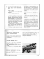
MAIN FEATURES
Engine
Twin cylinder, 4-slroke
Cylinder disposition
Bore
Stroke
Displacement
Compression ra tio
Max torque
"v~
90"
86 mm
76 mm
948,8 cc
9.2 to 1
6.6 kgm at 5200 rpm
Valve gearing
O.H.V., push rod operated .
Carburalion
N. 2 Dell'Orto carburettors VHB 30 CD ( right),
VHB 30 CS (left).
Lubri cation
Pressure, by gear pump.
Wire gauze and cartridge filters in oil sump:
Normal lubrication pressure : 3.8 -:- 4.2 kg / sqcm
(54-60 p.s.i.).
Controlled by pressure rel ief valve.
5
Generator-Alternator
Front, on the crankshaft (14 V • 20 A).
Ignition
By battery, with doubl e contact breaker and automatic advance.
Ign ition data:
Starling
Moto Guzzi V1000 G5 Owner’s Manual
-
Initial advance (fixed)
-
Automatic advance
+ II.)
31 '
31 · -+- 33·
-
Full advance (I.
-
Contact breaker gap: 0.37 -:- 0.43 mm
(.014-.016")
-
Spark plugs:
-
Plug points gap : 0.6 mm (.023" )
-
2 ignition coils filled on the frame on top of
the engine.
Marelli CW 7 LP
Bosch W 225 T2
Champion N 9 Y
AC - 44XL
Lodge HLNY
Electric starter (12 V - 0.7 KW) wilh electromagnetic ratchet control. Ring gear bolted on the
flywheel. Starter bullon (STARn on R/H of handlebar.
4-5
,
6
Transmissio n
Clutc h
Dry type, twin driven plates. Hand con trolled by
lever on the left side of handlebar.
Primary drive
By gears. Ralio: 1.235 to 1 (Z
Gear box
5 speeds, fronta l engagement, constant mesh
gears. Cush drive incorporated. Pedal operated
on L/ H of vehicle.
Gear ra lios:
Low gear = 1 10 ,
(2 :=: 14/ 28)
gear = 1
gear = 1
3"
4th gear = 1
High gear = 1
'"'
Secondary d rive
= 17/ 21).
to 1.388 (Z '= 18/ 25)
to 1.047 (Z = 21 / 22)
to 0.869 (Z
= 23/ 20)
to 0.750 (2 "" 28/ 21)
By cardan shaft. Bevel gear set.
Ra ti o: 1 to 4.714 (Z = 7/ 33).
Overall ralios (engine-wheel):
Low gear = 1 to 11.643
'"'
gear = 1
gear = 1
3"
4th gear = 1
High gear = 1
:'
10
10
to
to
8.080
6.095
5.059
4.366
,
Frame
Duplex c rad le, tubular structure.
Wh eels
front and rear: spoked rims WM 3/2.15 - 18" .
Tires
Front: 100/ 90 H 16 (MT 16).
Rear: 110/ 90 H 18 (MT 18).
Brakes
Front wheel
7
,
Twin disc b rakes, two independant controls with
hydraulic lines and twin cylinder calipers.
~
Controls:
Right front brake: hand controlled by lever connected to master cylinder on R/ H side of handlebar.
Left front brake: pedal controlled at same time
as rear brake.
Moto Guzzi V1000 G5 Owner’s Manual
-
Disc 0 300 mm (11 .8")
-
Cylinder 0 38 mm (1.49")
-
Master cylinde r fo r hand cont ro lled R/ H brake:
12.7 mm (.5").
6-7
8
Rear wheel
Disc brake, controlled by hand lever and pedal
on R/ H side of vehicle, hydraulic hose and 2.
cylinder caliper.
Rear brake and front b rake are interconnected
by an hydraulic circuil.
-
Dimensions and we ights
Disc 0
242 mm (9.5" )
-
Cylinder 0 38 mm (1.49 " )
-
Master cylinder 0
15.875 mm (.624").
Wheelbase
Length
Width
Height
Min. g round clearance
1.470
2.200
0.850
1.100
0.150
mt (56" )
ml (86,5" )
mt (33")
ml (46" )
mt (6")
Weight abt 220 kg (485 Ibs).
Performance s
Top speed, solo riding: abt 190 km (120 mph).
Fuel consumption: abl 5.6 I x 100 km (approx.
35 mpg).
9
Fuel and oil capacities
Group or part
Quantity
Recommendation
Fuel tank
24 I (6.6 US gls)
Gasoline 98/100 NO-RM
Reserve (warned by light)
4 I (ab! 1 US 911
Oil sump
3 I (ab! 3 q ts)
Gear box
0.750 I (ab! 20 oz)
Rear dri ve bo x (bevel gears)
0.250 t (abt 9 oz)
of which 0. 230 (6 oz)
0.020 (II. oz)
Fron! fork (each leg)
Braking circuits (front and rear)
Moto Guzzi V1000 G5 Owner’s Manual
i
0.080 I (abt 2 oz)
Oil «Agip Sint 2000 SAE 1 0/50~
Oil
~Agip
F.l Rolra MP SAE90..
Oil .. Agip F.1 Rotra MP SAE 90~
Oil «Agip Rocol ASO/R~
Fluid uAgip F.1 ATF
Dexron ~
Fluid «Ag ip F.1 Brake flu i d SAE J 1703»
8-9
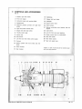
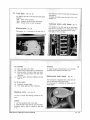
10 CONTROLS AND ACCESSORIES
(fig. 2)
1
Caliper. righ t I ront brake.
16
Saddlebag.
2
Front turn signal.
17
Caliper, left Iront brake.
3
Instrument panel with warning lights.
18
Headlight.
4
Speedometer.
19
Clutch control lever.
5
Reservoir (master cylinder) lor right front
brake.
20
Front bumper.
21
S
Righi fron t,. brake cont rol lever.
But tons controlling: horn, flashers, and turn
signals.
7
Engine start and stop button.
22
light switch.
8
Throttle control grip.
23
Lock for fil ler cap cover opening.
9
Ignition key.
24
Starter control lever on carbu retlors.
10
Rev-counter.
25
Gear shilt pedal.
11
Left front and re ar brake contrOl ped al.
26
Rear brake caliper.
12
Foo trest.
27
Rear turn signal lamp.
13
Master cylinder left front b r ake and rear
brake.
14
Pillion foot rest.
15
Rear bumper.
"Right» or .. left» in the text are lor controls seen
Irom the riding position.
11
1
17 18
2
34567891011
19 20
'21 '2'2 '23
12
'24
'25
13
14
15
16
26
27
,
Moto Guzzi V1000 G5 Owner’s Manual
10 - 11
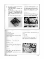
12
IDENTIFICATION DATA
(fi g. 3 )
Spare parts
Every motorcycle is identified by an identification
plate on the frame downtube and one serial number stamped on the engine crankcase.
The identification plate number is also mentioned in the motorcycle log-book and identifies the
vehicle to all legal effects.
In case of part replacements , ensure that «original Molo Guo:zi spare paris .. only are used.
The use 01 non-genuine p arts Invalidates every
wa rra nt y right.
Warranty
Th e wa rranty Is vali d for a period of 6 months
with a limitallon to 10.000 km Irom th e seiling
dale and expires In case of modifications to the
motorcyc l e or parteclpalion to racing competitions.
Tires as well as parts or accessories which are
not manufactured In the ~Selm m - Molo Guzzi
Factories », are nol included In these wa rranty
terms.
Each new motorcycle is supplied wi th a «coupon-book_. It has to be carefully kept with all
other circulation papers as it is !he only documen t entitling the owner of the motorcycle to be
recognized the warranty right by ~Seimm - Moto
GU.1.:Zi~, in accordance with its general conditions
of sale.
13
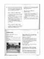
INSTRUMENTS AND CONTROLS
(fig. 4)
Speedometer, km or miles counter.
2
Warning light (green), lefl turn signal.
3
Warning light (green). right turn signal.
4
Warning light (red for USA), high beam (blue
for Europe), high beam.
5
Warning light (orange). 11 is lit when the
transmission (gearbox) is in neutral.
6
Warning light (red) indicating current delivery from generator. It must go out when the
engine reaches a cerlain number of revolutions.
7
Warning light ( r ed) , oil pressure gauge. It
goes out when the oil pressure is sullicient
for normal engine lubrication. If it does not
go out, this means the oil pressure is not
correct. In such event, the engine has to be
stopped immediately and all circui ts have to
be checked.
8
Warning Ught (green) indicating parking brakes engaged. This warning Ught flashes by
turning the ignition key to position «2~ (see
fig. 5). If th e s ide stand is not raised, the
engine cannot be started.
Warning light (red for USA) indicating parking light and low beam on. Warning light
(green for Europe) indicating town driving
. " Iight and low beam on.
9
Moto Guzzi V1000 G5 Owner’s Manual
12 - 13
14
10
11
12
13
14
Warning light (red) indicating incorrect flu id
level in Iront left and rear brake reservoir.
When Ihis warni ng light comes on, top up
the Ilu id leve! and Check the braking Circuit
has no leakages.
Warning light (red), luel reserve. To use the
reserve luel , bring the tap lever on the righ t
fuel tank in position ~A~ (Iig. 10).
Cou rtesy light switch (available).
Switch. r ig ht and left rear emergency I lashers.
Odometer or km counter reset.
Ignition key
(Iig . 5)
1 This key has 3 pos itions :
«OFFD
In line with the mark on panel : machine
at standstill, key removable.
«AH
In line with the mark on panel (turned
clockwise ): machine ready to be started.
All circuits on. Key not removable.
~ B~
In line with mark on panel (turned clockwise): machine at standstill. With switch
" A D in lig. 6 in position «OD'parking lights
are on. Key removable.
2
Rev-counter.
Light switch
(Iig. 6)
Are located o n the left handlebar and have 4
positions,
Switch
s
Butto ns "c..
~ 5H
Horn.
~6H
Flashing light.
Switch «B»
With switch ~ A ~ in position
«3.. Low beam.
«4" High beam.
"A~
«O H Parking lights.
«I » Low beam.
..2H lights 011.
«1~:
Switch
«7»
«8"
15
« D~
Right turn lights.
left turn lights.
Ho rn , fl ashing light and turn
signal button s (Iig. 6)
Engine starting and emergency
stop button (Iig. 7)
Are filled on the L/ H 01 handlebar.
Right on handlebar. With ignition key in position
,
,
Moto Guzzi V1000 G5 Owner’s Manual
14 - 15
16
~A~ (fi g . 4) the engine is ready to be started.
To
-
start the engine proceed as follows :
ensure switch .. B ~ is in position ~1~ (run) ;
pull th e clutch lever completely;
on a cold engine bring starter lever ~B~ in
the start position (fig. 28);
- press start button .. A~ (s tart).
To stop the engine in case of an emergency:
- shi ft switch «B~ to position ,,2~ (OFF).
Aft er stopping the engine, turn ignition key (fig. 4)
an ticlockwise until mark ~OF F ~ is in line with the
mark on the panel and take out the key.
Clutch co ntrol lever
Left, on the handlebar. Use it only for engine
starting and gearshifting.
Right front brake control lever
( .. F... fig. 7)
Right, on handlebar. This lever is suitably connected to the master cylinder and operates on
right front brake disc.
Easy start leve r on carburettor
(fig. 28)
This lever for starting a cold engine is located
near Ithe left cylinder head cover:
.. B» Start position.
.. C,. Riding position.
Throttle grip control
(<<E,., fig . 7)
Right, on the handlebar. Throttle is opened by
turning towards the rider and closed viceversa.
Gear co ntrol
Positions:
-
2nd, 3rd. 4th, and top gears : rear lever towards the ground.
(fig. 9)
17
To obtain access to the filler cap it is necessary
to turn key "A ~ on the protection cover anticlockwise. when the cover an d cap can be lifted.
This pedal is located on the left hand side of
the motorcyc le.
low gear: front lever towards the ground,
The control pedal is located on the right side 01
the motorcycle and is Jinkconnected to the flu id
reservoir (mast er cylinder) group .
It operates both front left and rear brakes at the
same time.
Fuel filler cap
(fig . 8)
-
Tw in brake control , front left
and rear brakes (fig. 16)
Fu el leve l
(<<A», fig. 10)
The fuel level (reserve) is warned by a lighted
indicator on the panel (~ 11 " in fig . 4) which is
connected with cutout ~A" fitled on the right front
of the tank.
Before actuating this rocking pedal pull the cl(Jtch
lever completely.
,
Moto Guzzi V1000 G5 Owner’s Manual
16 - 17
18
Fuel taps
(~ B».
fig . 10)
Are fitted at the rear of the tank and have th re e
positions:
~ON»
Open, lever upwards .
.. RES» Reserve, arrow on lever downwards.
~ OFF» Closed, a rrow on lever horizontal.
Electrovalve
(fig. 28)
Electrovalve «An is mounted on the left side 01
Key co ntrolled
.. h
~2»
«3»
«4 ..
Rear stop light, horn, flash .
Slarier relay , warning light «n», electrovalve.
Warning lights: Oil, gen, brake, fue l, headlight, low and high beams and their warning lights.
Parking lights, instrument lighting, warn ing
light «L».
Additional courtesy light.
Turn signal lights and their indicators.
Steering lock
II comes into ac tion when the key in fig. 5 is in
position ~2».
Terminal block w ith fu ses
II is
and
side
N. 6
(fig. 11 )
located on the right side of the motorcycle
can be accessed to by removing the R/ H
cove r and then the terminal block cover.
fuses of 16 A are fitted.
19
Unlocking
Out of key control
«5»
«6»
the motorcycle under the fuel tank and feeds the
carburellors.
(..A».
• insert the key in the lock set. turn it counterclockwise, then release it and Slip it off.
Motorcycle side stand
(fig. 13)
The motorcycle is equipped with a side jack for
use as side stand during brief sto ps.
For long stops it is advisable to always use the
cenle r stand.
fig. 12)
To lock or un lock the steering proceed as follows :
Locking
• turn the handlebar fully to the right;
• insert the key in the lock set. turn it counterclockwise, push it right in , re lease It, an d slip
it ou t.
Moto Guzzi V1000 G5 Owner’s Manual
18 - 19
20
Wh en it is in the parking position (I ully out), a
special device cuts off the cur ren t.
When key of switch "B~ is in line with the mark
on the revcounter bracket, warning light (.. 8~,
fig. 4) on the panel warns by flashing thai before
starli ng the side stand has to be raised or else
the byke will not start.
RIDING INSTRUCTIONS
Control s before start ing
Ensure that:
• ignition key is in Ihe 'start position (mark ~A~
on key has to be in line with mark ~B" on the
rev-counter panel (fig. 5):
• there is sufficient fuel in the tank (warning
light .. fuel» is oul):
• warning light .. brake~ (fuel level in braking
circuit (reservoirs) is nol Iii):
•
the oil in the sump is at correct level:
Ihe following warning lights are Iii: "oil~ (red).
(red), when night riding: .. 1» red for USA,
green for Europe):
•
" gen ~
• «slarler» control lever for cold engine start is
in position .. 8» (fig. 28).
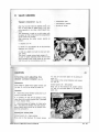
Starting a co ld engine
Afler checking the above, turn twist grip 'I. lurn
towards the rider , pull the clutch lever fully, and
press start bulton .. A » (fig. 7).
Moto Guzzi V1000 G5 Owner’s Manual
21
As soon as the engine has started and before
returning the starler lever in riding position .. B~
(fig. 28) allow t he engine to idle for a few seconds in the hot season and a few minutes in
the cold season.
Should the slarter lever be left in starting position «B~ when riding , there would be irregular
carburation and increased fuel consumption: worse still, the engine might sei ze because of too
much petrol going into the cylinders.
Caution - If the orange light in the panel does not
light up when mark .. A" on the key is lined up
with mark .. B» on the rev-counter bracket (fig . 5),
this means a gear is engaged and the pedal has
to be moved to the neutral position in between
low and second gear.
Starting a hot engine
Same as for a cold engine, except that in this
case "starter» lever has not to be set to the start
posilion .. 6» (fig. 28) as this would richen the
carburation too much.
20 - 21
-
22
On the way
To change up or down pull the clutch lever comp/etely and engage the next gear. Release the
clutch lever gently, accelerating at the same time.
The gearshift pedal should be actuated firmly
and accompanied with the foot.
When shifling down to a lower gear, operate the
brake and throttle controls gradually so as not to
cause the engine to over rev when the Clutch
lever is rel eased.
-
,
Stopping th e motorcyc le
Close the gas, pull the brake lever "d press
down the brake pedal gently, p ulling the clutch
lever only when the byke is almost to a stan dstill.
Iy the Iront one - should be used with cautio n.
To stop t he engine turn the ignilion key to posilion «OFF" (fig. 4).
When the engine is stopped, always close the
fuel laps.
Parking
When parking al night on insufficiently lighted
roads, switch on the parking lights by turning the
ignition key to the position where mark «A" on
the key is in line with mark "B~ on the rev-counter panel (fig. 5) and the light switch in fig. 6
is in line with position «ON_.
Then remove the key and lock the steering. See
"Steering lock~ fig. 12.
This operation should be done with co-ordinalion so as to keep the vehicle under control.
To reduce the speed gradually, use the engine
braking power by correctly changi ng gear, paying allention nol to cau.e th e engine ta aver rev.
On wet or slippery roads, the brakes - especi a/-
23
RUNNING IN
During the running · In period follo w strictly these
recommendations:
to prevent the various engine groups from undergoing abrupt changes of temperature.
1 Before starting allow the engine to warm up,
lelling it idle for a . more or less period of time,
according to the external temperature.
4 Make sure all the operation specified in the
service voucher have been carried out at the staled mileages.
2
5 Dont forget that proper bedding down .01 all
components w ill only occur alter several thousands of miles have been covered. This will allow
you to obtain excellent performance fro m you r
mo torcyCle lor a long period of time.
Never exceed m ax imum permissible speeds
in each gear. Avoid running at the same number
of revolution for long periods but change gear
frequently.
3
Before stopping, reduce the speed gradually
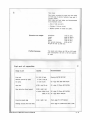
Maximum running in speeds
Di stance covered
Maximum permissibl e spees
Low gear
2nd gear
3rd gear
4th gear
High gear
Up to 800 km (500 miles)
45 km
(29 mph)
65 km
(40 mph)
85 km
(53 mph)
100 km
(63 mph)
115 km
(72 mph)
From 800 km (500 m iles)
to 1600 km (1000 miles)
55 km
(34 mph)
80 km
(48 mph)
105 km
(63 mph)
120 km
(74 mph)
140 km
(87 mph)
From 1600 km (1000 miles)
to 3000 km (1900 miles)
Moto Guzzi V1000 G5 Owner’s Manual
Gradually increase the above limits "p to the maximum admissible speed.
22 - 23
24
After the first 500 km (300 miles)
1000 km (600 miles)
Change th e crankcas e oil. Should the all level
tall under the mInImum level mark before the engine has reached 500-1000 km (300-600 miles), it
will be necessary to change the all instead of
topping up.
Recommende d oil : "Agip Sint 2000 SAE lQW!SO*.
Check tightness of all nuts an d bolts.
Adjust valve roc ker clea rance.
Check contact breakers gap_
Check spokes tension.
25
MAINTENANCE AND ADJUSTMENTS
Adju sting the clutch control
lever
(fig. 14)
Adju sting the right front brake
control lever (I ig. 15)
If the Iree play al the handlebar is more o r less
than 3-4 mm (. 118-.157"), act on adlus ter "A~ to
restore the correct play
This adjustmen t can also be carried out by slackening counlernut "C~ and acting on adjuster
"B ~ on the righ t side of the gear box.
Proceed as follows ;
• insert a feeler gauge «A» be tw een the floater
in master cylinde r an d the control lever end;
• turn thumb scre w ~B» to obtain the correct
play which is 0.05 -;- 0.15 mm (.0019·.0059" ).
,.
Moto Guzzi V1000 G5 Owner’s Manual
24 - 25
26
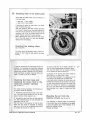
Check ing wear of the brake pads
Every 5000 km (3000 miles) check th ic kness of
the brake pads.
-
New pad
9 mm (.3543 ~).
Wear limit 6 mm (.2362"),
If thickness is below the wear limit. it is necessary to replace the pads.
After this operat ion has been carried out there
is no need to bleed the air from the braking circuits but only to operate the contrOl lever on the
handlebar (,,8» in fig . 15) several times until the
caliper pistons reach their normal position.
When replacing the pads, check also the condi tion 01 the fluid ducts: il in any way damaged ,
replace them immediately.
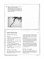
Checking the braking discs
(fig. 16 and 17)
The discs should be perfectly clean. without oil.
grease or other impurity, also without any deep
scoring.
In case o f replacement or overhauling of the bra ke discs, it is necessary to check their flutte ring .
This control is done using a suitable gauge which
should never exceed a reading of 0.2 mm (.0079").
II the «flulte ring ~ is higher, have the discs checked in a shop of one of our dealers.
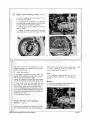
Checking the fluid level and
rep lac ing the brake fluid in th e
reservoirs (master cy linder)
(fig. 16 and 17)
For proper braking operation, the following instructions should be observed:
1 Periodically check the fluid level in the reservoi r. This level should always be over the transparent section of the reservoi r .. C».
Periodically check and top up fluid reservoir
«A~, arler loosening plug .. D» and removing the
diaphragm (see fig. 16).
The flu id level in the reservoir for the left front
brake and rear brake is indicated by warning
light "8~ in fig. 4 on the instrument panel which
is actuated by cut-out «CM (fig. 17).
2
Moto Guzzi V1000 G5 Owner’s Manual
"
To top up. undo cap «D» on master cylinder «A»
(fig. 16), alter disconnecting the electric wires.
Use only fluid ta ken from an original container
to be opened just before pouring in.
27
3 Change all the braking fluid every 15.000 km
(9000 miles) or at least once a year.
For good brake operation, it is necessary for the
fluid ducts to be always full of airless flu id.
A long and elastic movement of control lever «B»
indicates the presence of air bubbles in the ducts.
To wash the braking circuits use only fresh fluid.
Never use alcohol for washing or compressed
air to dry. For metal paris use trichloroethylene.
Recommended fluid: «Agip F.l Brake Fluid SAE
J 1703».
Bleeding th e air from the
braking circuits (fig. 16 and 17)
This operation is required wh en the movement
of the cont rol lever on the handlebar or the pedal
is long and elastic due to the presence of air
inside the b raking circuits.
Proceed as follows :
26 - 27
28
Right front braking ci rcuit
(fig . 16)
• turn the handlebar until the reservoir
in the horilQntal position;
~A*
is
• if necessary, fill up reservoir .. A~ (e~suring
that during the bleeding opera tion, the fluid does
not drop below the transparent section);
• bleed by acting on one caliper half "F_ at the
time as follows:
1 Remove the rubber covers and fit a transpa·
rent f1exible duct ~G~ on drain plugs "E" wi th
"
,t he other end of the duct plunged into a tran sparent container ~H~ partially filled up with Ii·
quid of Ihe same type.
2
Loosen drain plug
brake fluid in the braking circuits ~ , excep t point
. I~ and in .Sraking ci rcui t for the right front
brake» except points ~3" and ~4 M .
29
~E_ .
Level
Completely actuate brake control lever ~ Bseveral times, releasing it slowly and wailing a
few minu tes before pulling il again.
Repeat the operation until the duct end plunged
into the transparent container emits airless fluid .
3
It i's indicated by warning light «B~, fig. 4 on
the panel. When 11 tights up It is necessary to
top up.
Bleeding
4
Keep control lever ~B~ fully pulle d and lock
drain plug «E». Then take out plastic duct .. GM
and re-fit the rubber cover on the drain plug.
If the air bleeding has been carried out co rreclIy, a direct and efficient working 01 the fluid w ill
be perceived immediately after the initial idle movement of (ever ~B~.
If not, repeal the operation .
3
4
Press down completely cont rol pedal ~B». etc.
Keep the pedal pressed down , etc.
Front left and rear braking
circuit (fig. 17)
Follow the same ,procedure as described in chapter «Checking the fluid level and replacing the
Moto Guzzi V1000 G5 Owner’s Manual
18
28-29
30
Ad justing the fron t left and rear
brake pedal (fig. 18)
counternul ~B~, and screw in or oul fork "C ~
until control pedal «F _ comes to the desired
position;
Check clearance between floater and control lever ~G,. (on master cylinder) , proceeding as fol-
• re-fil retaining pin and circlip.
This done, loosen counlernul ~ E ~ and adjust
screw "D ~ for lever return .
lows:
• Iii a feeler gauge between the f,loater in master cylinder and the end of the control lever.
Turn thumb screw " A~ 10 obtain the correct play:
0.05 -i- 0.15 mm (.0019-.0059");
•
take off the eire lip. slip off the pin and loosen
Adjusting th e rear suspensions
(fig. 19)
The ex ternal springs of the reaf suspensions can
be adjusted to three positions using lever "A~ in
the kit.
If an irregular operation of th e hydraulic dampers
is noticed, have them checked In one of our dealers workshops.
Caution - Do not forget that the two springs have
to be adjusted to the same position to ensure
good stability to the motorcycle.
Adjusting the steering
31
"
(fig. 20)
For safe riding the steering has to be adjusted
so as to allow free movement to the handlebar,
but without excessive play.
To correctly adjust, proceed as follows:
.A~;
-
slacken steering head fixing bolt
-
undo steering head nut .. B~;
-
screw in or out adjuster nut .. C~ to take up
the excessive play.
This done, tighten nut «8 .. and steering head
fixing bolt «A~ .
It is well lor this operation to be carried out by
one of our dealers.
Moto Guzzi V1000 G5 Owner’s Manual
30 - 31
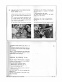
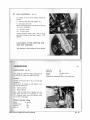
32
REMOVAL OF WHEELS
Fron t wheel
• undo the screws securing the muffler to frame
(left), loosen the strap securing screw. and take
out the mufller Irom the exhaust pipe ;
(fig. 21)
To remove the front wheel, operate as follQws :
• undo scews .. F" and .. G» securing caliper "A"
to the left fork cove r. Now take OU~ caliper from
the brake disc by lilting it slightly;
• undo spindle retaining nut ftS» on the right
side ;
•
undo screws " C" fixing fork covers to spindle:
•
withdraw spindle .. 0" ;
• lilt up the front part of the motorcycle just
sufficiently to allow the brake disc to be taken
out of the caliper still mounted on the right lork
cover.
Re-fitting is a reversal of the removing operation
bu t particular atten ti on should be paid to the position of spacer .. E» on the right.
Rear whee l
(fig. 22)
To remove the rear wheel, proceed as follows:
•
undO nut u8 », drive box side;
• undO screw securing spindle «C» to the rear
fork arm :
• wi thdraw spindle «0» from drive box. brake
hob, swing arm:
•
ZI
• tU"n the wheel and cheek its truing using a
suitable gauge. II necessary adjust the right or
te ft spokes untit the wheet turns property. This
Check has to be done after the first 500 km (300
miles) and then every 1500 km (900 miles).
33
withdraw braking disc from caliper «E,,:
• after disconnecting the parking brake contro l
cable, slip off the p late complete with hydraulic
and mechanical calipers. Do not disconnect the
hydraulic duct:
• lean the vehicle to the right so as to allow
whe el «F» to be slipped off from the rear fork
arm and the drive box.
When fe-fitting, proceed in reverse sequence,
making sure to insert the plate complete w ith calipers in th e fear fo rk lug and to hook the parking brake cable to its operating rod.
Adjusting the spokes
Check tha t all spokes are tight and trueness of
the wheel as follows:
Moto Guzzi V1000 G5 Owner’s Manual
,...;;;.;~-~---
" ...._--- --.;;;= )
32 - 33
34
.
,
pendant on them. Therefore it is not advisable to
use tires having less than 2 mm (1/16" ) thickness thread.
An incorrect tire pressu re may also affect the
vehic le stability and cause ra pid deteri o ration 01
the tire.
Recommended pressures are:
Wheel balance
To improve the vehicle stability and decrease vibrations at high speeds, the wheelS have to be
kept well balanced.
Proceed as follows:
...
• ensure that all spokes are light~ne d an d the
wheel is true;
Ir
•
Front whee l
remove the wheel an d suspend it on a fork;
• lightly spin the wh eel several times and see
il it always stops in various positions, thus indicating a co r rect balance ;
-
solo or wi th pillion: 2.1 kg/ sqcm (30 p.s.i.) .
• if on e point of the wh eel always stops at the
bottom, pu t a balance weight on the spoke opposite this point;
- solo: 2.4 kg/ sqcm (34 p.s.i.);
- with passenger: 2,6 kg/sqcm (36 p.s,L).
T he above fi gures are fo r normal r iding (cruising
• repeat the operation until the wheel is correctly balanced , then fix the balance weigh ts to the
spokes by means of pliers.
Balance weight are readily availa b le from our
dealers.
speed).
Rear wheel
II using the motorcycle at consta nt high speed or
on hig hways, it is recomme nded to increase the
pressu re by 0.2 kg / sqcm (3 p.s.i.).
Mounting ti res on rims
Tires
If the tires have an arrow stamped on on e side,
this has 10 tu rn cloc kw ise for the rear wheel and
anliclockwise for the fron t wheel.
Tires are included in the co mponen ts which must
be very carefully checked as the vehic le stability.
riding comfort an d even the ride r's safety are de-
LUBRICATION AND MAINTENANCE
Monthly or about every 3000 km
(2000 miles)
35
trueing (see Remova l of wheels ~Adjustm e nt 01
spok es»).
•
Ct:eck rocker clearance (see Valve gearing).
•
• Check: the elec trolyte level in the battery (see
Electrical Equipment .. B attery ~ ) .
Eve ry 1500 km (900 miles)
Periodically
• Check ti re pressure (see Removal of wheels
.. Ti res~).
Eve ry 500 km (300 miles)
• Check the cran k: case oil level (see Engine
lubrication).
After th e first 500-1000 km
(300-600 miles)
• Renew the oil in the crankcase (see lubrications «Engine lub r ication~).
• Check: tightness of all nuts an d bolts.
• Check tightness of all wheel spok:es and wheel
• Check lightness 01 all wheel spokes. Ensure
the wheel is tr ue (see Removal 01 wheels ~Adjust
ment of spok:es») .
Every 3000 km (2000 miles)
• Replace the crank:case oil (see lubrications
.. Engine lub r ication~).
• Chec k: rocker clearance (see Valve gearing
~Adjusting rocker clearance»).
• Check oil leve) in gearbox (see Lubrica ti ons
.. Lubrication Of gearbox»).
Eve ry 5000-6000 km
(3000-4000 miles)
•
Check the fluid level in the rese rvoi r (m aster
I.
Moto Guzzi V1000 G5 Owner’s Manual
34 - 35
36
• Replace the oil filler cartridge (see Lubri cati ons «Repl1\c ing the oil Ii Iter cartridge and cleaning the wire gauze lil1er ~).
cylinder) lor the right fron t brake. An incorrect
fluid level for the left fronl brake and rear brake
is warned by an optical indicator (red) on the
panel (see Mainte nance and adjustm ents ~ Che
eking and replacing the brake fluid»).
After the first 20.000 km
(12.000 miles)
Every 10.000 km (6000 mi les)
•
-
Have your dealer make the following controls:
checking conditiv., of wheel bearings;
checking thai steering bearings are sufficiently greased (Agip F.1 Grease 30).
• Replace the oil in the fork legs (see Fork
lubrication).
• Clean starter motor and generator commutators using a clean rag lightly moistened in petrol.
• Clean the fuel tank, fuel fillers, and pipes
(se e Carburatlon ~Cleaning fue l tank, fuel taps,
fuel filters, and pipes~)_
• Replace the oil in the gearbox (see Lubric ations "Lubrication of the gearbox~).
• Replace the oil in rear drive box (see Lubricatio ns "Lubrication of rear drive boxD).
• Clean and smear with jelly all battery connections (see Elec trica l equipment u8aUeryD).
• Rep lace the air filler (see Carburation "Air
fil ler cartridge»).
Every 15.000 km (9000 miles)
• Replace the fluid in the braking circuits (see
Maintenance and adjustm ents "Checking and replacing the fluid in braking circuilsD).
LUBRICATIONS
37
Engine lubrication
(fig. 23)
Chec king the 0 11 level
Every 500 km (300 miles) check level of crankcase oil.
Correct level is in proximity 01 the top mark on
the dipstick .. A».
II lower, top up with oil of same quality and
density.
All ow the engine to Idle a lew minutes belore
checking the oil level, ensuring the liller capdipstick uA~ is lully screwed in.
,
Repl acing the c rankcase oil
After the lirst,5OO-1000 km (300-600 miles) and
later on every 3000 km (2000 miles) or so, replace the oil in the crankcase. Do this operation
on a warm engine, allowing the old oil to drain
completely before adding fresh oil.
"AD
«8»
Filler cap dipstick.
Oil drain plug.
Quantity required: 3 I 01 .. Agip Sint 2000 SAE
10W/50~ (approx. 3 q ls) .
Repl acin g the oil filter cartridge
and cleaning the w ire gauze filter
(fig. 24)
Every 15.000 km (9000 miles) (5 oil changes), replace the lilter cartridge proceeding as follows:
L_ _
~_~__~_
______Jl...J 23
Moto Guzzi V1000 G5 Owner’s Manual
•
•
undo plug ~B" and let the oil drain fully ;
undo fixing screws and remove the 011 sump.
36 - 37
38
t
Filter cartridge ~A~ and wire gauze lilter «0» are
mounted inside the sump:
Lubrication of the gearbox
• undo lilter cartridge ~A» and replace it with
an original one.
When replacing filter cartridge ~A», it is recom·
mended to also remove wire gauze lilter .. 0».
washing this in a petrol ba th and drying it with
a compressed air jet. Belore mounting it, blow
through the oilways in the sump 'With compressed air.
Finally, do not forget to replace the sump gasket.
This servicing is best done by our dealers.
Every 3000 km (2000 miles) ensure the oil level is
nearly at the top of inspection hole ~ B ~. 1/ lower.
top up wilh oil of same quality and density_
(fig. 25)
Repla cing the 011
Every 10.000 km (6000 miles) replace the oil in
the gearbox.
This operation has to be done on a warm engine
when the oil is more fluid and easily drained.
"
"A»
Filler cap.
«8»
Level checking cap .
Let the old oil drain fully before introducing
fresh oil.
.. C»
Oil drain plug.
"A,.
Quantity required: 0.750 I (abt 25 oz) of «Agip
Rotra MP SAE 90».
~B»
~ C»
Filler cap.
Level cap.
Oil drain plug.
" required: 0.250 I 01 which 0.230 I (3/.
Quan tity
pint) of oil ~Ag ip F.l Rotra MP SAE 90» and
0.020 I (approx. '/. oz) of «Agip Rocol A SO/ A».
39
•
•
Lubrication of rear drive box
(Iig. 26)
Checking the oil level
Every 3000 km (2000 miles) check that the oil level is nearly skimming the hole of level cap "A*.
If lower, top up with oil of same quality and
density.
011 change
Every 10.000 km (6000 miles) change the oil in
the rear drive box.
00 this on a warm engine as the oil is more
easily drained.
Moto Guzzi V1000 G5 Owner’s Manual
38 - 39
40
Fork lu bri catio n
(fig. 27)
To replace the oil in the fork legs, proceed as
follows:
•
•
undo the drain
pl~g
with gasket
• undo allen screw ~B~.
Before introducing fresh oil allow
oi) to drain completely.
~A~
Oil drain screw.
«B»
Oil filler screw.
~II
~A~;~
the fork leg
Quantity required: 0.070 I (abt 1 and J/. oz) or
about half a glass for each leg of "Agip F.t ATF
Oexron».
Lu bricati o n of th e steering an d
rear fo rk bearings
This operation is besl carried out by our dealers.
"
..._-
CARBURATION
Ca rburettors
41
(lig. 28)
This model fits 2 Dell'Orlo make carbureUors type WHB 30 CD (right) and WHB 30 CS (left).
Idling jet
50
Starter jet
80
Needle
V 9 (2nd notCh)
Floate'
to gr
Idling screw adjustment: open 1 and a half turns.
Control s
Throttle contrOl grip (~B .. in fig. 7) on the right
hand lebar.
Starler lever, for starting a cold engine, in the
lett cylinder head cover.
«B~
Starting position.
~CD
Riding position.
Note - With the Slarter lever in position ffC", (riding), check that there is a clearance of 3 mm
(.11") between cable ends and adiusler screw
~H ... of both carburettors.
Standard carb urellor setting
Choke
Throllie valve
Atomiser
Main jet
o
30 mm
40
265
130
Moto Guzzi V1000 G5 Owner’s Manual
40 - 41
42
Adjusting the carburation and
idling speed (hand adjustment)
(fig. 28)
•
Proceed as follows.
"
1 Warm the engine up to its normal runni n g
temperature.
2
Screw in fully idling adlusters
~E » .
3 Check with your han ds if th e exhaust pipe
pressures are equal. If necessary, act on screw
~O» of one carburettor until the exhaust pressu·
res of both carburetto rs are the same (idling
speed should be kept at no more than 900·1000
rpm and consequently it may be necessa r y to
screw in the screw of the carburettor for the cy·
linder giving a lower exhaust pressure, or screw
out the screw of the carburettor for the cylind er
giving a higher exhaust pressure).
4 Acting on screws «ED get the bes t carburation for each cylinde r (this is perceived by an
increase of rpm) and then adjus t idling speed
according to point 3.
5
Disconnec t one spark plug lead at the time
Adju sting the carburalion by
means of a vac uometer
In order to obtain a correct adius tment of the
carburation it is necessary to apply to our dea·
lers who can carry out this operation by means
of a vacuometer.
Air filter ca rtridg e
and check that in bo th cases the engine slops
aller firing 5-6 strokes. If it does not, screw out
screw ~D~ 0 1 the carburettor making the engine
fire more than 5-6 stroke or screw it in for the
carbu rettor making the engine fire less than 56 strokes.
6 Adjust idling speed at 900-1000 rpm by screw·
ing o r unscrewing both screws "D" by the same
amount.
7 Wi th the throttle grip closed, ensure there is
a clearance of 1-1.5 mm (.039-.059") between cable ends and cable adjuster screws .. F» ' of both
carbureltors.
8 Ensu re thai the throttle yalves open simultaneously by proceeding as follows: gradually turn
the throttle control grip and check that the exhaust pipe pressure increases in synchronization
with your hands (an assistant is necessary for
this operation).
If pressure increase of one cylinder is advanced,
act on its carburettor by gradually screwing in
cable adjuster uF», atter loosening con ternut .. G»,
until the synchronization of both exhaust pipes
pressure is reached .
gular fuel flow to the carburettors, it is neces·
sary to c lean the luel tank, the fuel taps, the
filters on the carburettors, and the fuel pipes.
All these parts are best cleaned using petrol and
dried 011 with comp ressed air.
43
•
(fig. 29)
Every 10.000 km (6000 miles) air filter cartridge
.. AD should be changed.
This filter is located in a sui table container to.
gether with the oil breather assembly, under the
fuel tank.
For this replacemen t it is recommended to apply
to our dealers.
Cleaning the, fuel lank, fuel taps,
fuel filter, and pipes
Every 10.000 km (6000 miles) o r In case of irre -
Moto Guzzi V1000 G5 Owner’s Manual
42 - 43
44
VALVE GEARING
Tappet clearance
(fig. 30)
After the first 500-1000 km (300-600 miles) and
later on every 3000 km (2000 mile~1 or any time
valve operation is too noisy, check l appe t clea-
-
compression loss;
-
overheating of engine ;
-
burning of valves.
rance.
This adjustment is made on a cold engine with
Ihe piston at TDC al the end of the compression
stroke (valves fully closed).
Afler removing the rocke r covers, operate as
follows:
1
Slacken nul
« A~.
2 Screw in or ou t adjuster .. 8 » til! the following
clearance are obtained:
• 0.22 mm (.0086") for both the inlel and exhaust valves.
This check is made using a feeler gauge .. C*.
In case of higher clea rance, there will be noisy
valve o peration while if the valves do not close
fully there will be inconveniences such as:
IGNITION
45
«c- and «D ~ ·a nd move plate «E- by acting on
notCh ~ F ».
After seltlng to the correct distance, lock screws
~ c» and «D».
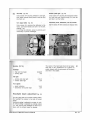
Che ck ing and adjusting the
double contact breaker (fig. 31)
Maintenance
Contact pOints «8 » - left cylinder
Every 3000 km (2000 miles) lightly moisten cam
fell pad «R. with a lew drops of engine oi l.
Bring cam to' the maximum lift, loosen screws
«G» and .. H * and move plate ~L » by acting on
notch «M».
Inspection
• remove the con tact breaker cover prior to undoing its securing screws;
• if contacts ~A " and ~ B » are greasy or dirty,
clean them with a petrol soaked rag. If damaged
or worn, rep lace them ;
• check points gap of breaker «A" (right cylinder - red cable) and breaker "8,, (left cyl inder _
green cable) wh ich should be in between 0.370.43 mm (.014-.016").
Adjusting the contact poInts
Contact points " A" - right cylinder
Bring cam to the maximum lift, loosen screws
Moto Guzzi V1000 G5 Owner’s Manual
31
44 - 45
46
•
After selting to the correct distance, lock screws
~G» and «H».
When adjusting the contact points, the ignition
timing should be checked as well (see following chapter).
,
pression stroke (both valves closed). At this stage, mark «D» stamped on the lIywheel (TOe 01
right cylinder) should coincide with mark .. 1" on
the inspection hole rim;
• rotate the flywheel clockwise until mark «2»
on the flywheel (fixed advan ce) coincides exac-
Control and adjustment of
ignition timing «fixed advance»
(fig. 32)
Inspection
• remove the rubber cap which seals the inspection hole located on the R/ H side of the reducer
box opposite the flywheel ;
• to find the exact moment when points .. A~
and ~B» (fig. 32) starl separating, it is advisabl e
to use an appropriate timing light to be se t up
between the breaker feeding clamp being checked and the ground.
Timing the right cylinder
• turn the flywhee l anticlockwise (engine (otatlon) until the piston is at the end of its com-
tly with mark «1,. on the inspection hole rim. At
this point, breaker contacts uA» should start to
open .
For this service it is recommended to apply to
our dealers.
47
Spark plugs
Timing the lell cylinder
• rotate the flywhee l counterclockwise
rotatio n) until the piston is at the end
compress ion stroke (both yalyes closed).
point mark uS" on the flywheel (ToC of
linder) should coincide with mark .. 1,.
inspection hole rim ;
(engine
of the
At this
left cyon the
• rotate the lIywheel clockwise until mark u3~
on the flywheel {fixed adyance~ coincides exaclIy with mark «I ,. on the inspection hole rim. At
this point. breaker uB" contacts (fig. 32) should
start to open.
II the contact points of breakers «A,. and «B ..
(fig . 32) do not start opening in the above positions. then ignition tim ing needs adjustment.
The type of spark plugs to be used is indicated
at pag e 5.
Spark plug points gap 0.6 mm (.023").
The spark p ~ugs are best cleaned with petrol
and a wire brush, using a needle for the inner
part.
In re-fitting the spark plugs, ensure they are started by hand for a few turns, completing then the
operation with the wrench in the tool kit. If not
properly started, the cylinder head thread may
get stripped.
For all even ts, the plugs have to be replaced
every 10.000 km (6000 miles) even if they appear
to be still in good condition.
IgnlIIon advance dala
Initial advance (fixed)
D" +- 2"
Automatic advance
31 ·
3,. +- 33"
Full advance (f. + a.)
Breaker contac t pOints gap : 0.37-0.43 mm
( .014- .016").
Moto Guzzi V1000 G5 Owner’s Manual
46 - 47
48
ELECTRICAL EQUIPMENT
Battery
The electrical equipment consists of:
•
•
Battery.
Starter molor with electromagnetic ratchet
control.
,
•
Generator/ alterna tor, located on the front side of the crankshaft.
•
Double contact breaker with autom. advance.
•
•
•
Rectifier.
•
Terminal block with fuses (6 fuses of ,,16 A,,).
•
Flasher relay.
•
Starter relay.
•
Headlight.
•
Tail tight, parking, stop, number plate.
Turns light indicator.
•
•
•
•
•
•
(fig. 33)
Battery is a 12 V type with 32 A capacity. It is
charged directly by the generator.
Access to the battery is obtained by:
unhooking lift ing lever "A» ;
rais ing the seat and keeping it up with rod
.. 8 »;
Ignition coils.
unhooking the rubber bands .. CD and disconnecting the electric wires ;
Regulator.
removing 1001 box.
Pulling a new battery Into service
1 Remove seals and plugs and introduce pure
Sulphoric acid with specific gravity 01 1,25 kg/I
and al temperature not lower than 15· C (59" F)
till the level is 5-6 mm (.10-.23~) over the top
of the plale separators or the splashguard.
Ignition switch.
light switch.
Turn indicators, horn and flashing light switch.
Engine starting and stopping button.
Electric horns.
such rate has remained constant for at least 3
consecutive hours of charging.
Normally, 6-8 hours charge are suffiCient.
2
Let the battery rest for two hours.
3 Charge the battery at an intensity equal to
about 1/1Oth of its capacity until the current intensity rate of the acid is about 1,27 kg / I and
Note - II the batteries are used in tropical climates (average temperature over 33" C == 92' F),
it is recommended to reduce the acid gravity to
1.230 kg/ I.
4 At the end of the charge, top up the acid,
plug up, and clean accurately.
Sel"\licing the battery under service c onditions
,
Rep lacemen t of light bu lbs
1 The electrolyte level should always cover the
separators. To top up, use distilled water. Never
add sulphuric acid.
Hea d light
49
•
(fig. 34)
UndO bottom screw ,,8,., withdraw the beam unit,
take out the bulbholders and replace the bulbs.
2 If too frequent water additions are required,
have the electrical system checked over as the
battery works in an overcharged condition and
will deteriorate quickly.
3 If the battery discharges quickly, the electrical system should also be CheCked over.
4 In case new or second hand batteries are left
unused for fairly long periods of time, it is a
good rule to charge them every month.
S Always keep the battery terminals spotlessly
clean and smeared with neutral vaseline.
6 Always keep the top battery cover dry, avoiding overflows of electrolyte which will reduce insulation and corrode the battery bracket.
Moto Guzzi V1000 G5 Owner’s Manual
33
48 - 49
50
Tall lamp
(fig. 35)
Number plale light
Undo screws «D~ securing reflector to tail light,
push bulbs inwards turning them to the teft. and
slip them out.
Undo screws "F~ securing the transparent reflec·
tor, push the bulb inward turning it to the left.
and slip it out the holder.
Turn signal bulbs
Instrument panel, tachometer, and rev-count er
(fig. 35)
Undo screws «e» securing the reflectors to the
lamps, push bulb inwards and turn it to the left.
slipping it off.
In re·f itting the reflectors, screw in uniformly and
moderately to prevent breakages.
Headlight
high and low beam
parking light
Slip the bulbs off their sockets and replace them.
The center of the high beam must not be higher
than 0.67 m (33") measured at 3 m (about 3.3
yards) distance with the motorcycle off the stand
and rider in the saddle.
Bulb s (12 V)
-
(fig. 35)
51
45 / 40 W
3W
Tail light
-
parking and slop light
number plate light
5/21 W
SW
•
Turn si gnals
-
panel indicators
tachometer rev-counter light
Headlight beam adjustment
1,2W
3W
(fig. 34)
For safe riding and not 10 trouble crossing riders.
the headlight has always to be kept at correct
height.
Horizontal setting is adjusted by screws "A~ while vertical setting is adjusted by undoing screws
"C~ and shifting the headlight by hand up or
down until the correct height is reac hed.
Moto Guzzi V1000 G5 Owner’s Manual
50 - 51
Fold-out page for Wiring Diagram
Moto Guzzi V1000 G5 Owner’s Manual
52 - Wiring Diagram
AZ
~
Q-@ AZ -
" G,lJ
-N
~
_
~
•
~
~
Wiring Diagram V1000 G5
See Page 52 for Legend
"
~~@
II . )---+
N
$
~~
~ ~
~~
IJ
•
0
@J
,
'
I ~~" r
~~
rF
II Iz
~.
"
"G
,,
y
,"
.. Whit..
.. elac~
~
~"
.. Vellow
= GrOffln
.. Red
~ 611la
,. Violet
RO
'" Pink
M
,. Orange
'" Brown
BH.j
GR
.. Wh ile -Black
_ Gray
"
= Bleu
8·'"
'" Bleu·BIBC~
V-N
_
G'''''n·Blac~
R·N
'" Red·Black
AZ-N '" B leu-BIBck
-@
,\,
0
--"-"--,I~
'>'II
I
f(
~
, IL-mJ
(
~
I)
~
I . -,
J.
.N
-'i- I;...
~
I:
•
®--
IIW
~=
~
,
D
II
,-
:~
.:. :':
~-'-y
'-V I
~
~
G
@~
VN
1
,!
""
"--"
~~
@J~
~
=-
'----'
y
~
@
@r
®-l~
~
.0
~
~
i~
,
[.
~ ~
, ,
IZ
@
.~
'1/
~ G.
~~:J
@/
,
N
@l,
I@I ~
~
.-
>
~
v-,
Ic,,,." •• I>1
"'@I
'I ~-O--+
~
N
~
dY
',~.
'
ADDITION TO THE OWNER'S MANUAL
FOR USA - MODEL 1980
I
I
Moto Guzzi V1000 G5 Owner’s Manual
1980 Addition
Front and Back Cover
These motorcycles conform with U. S. Environment Protection Agency Emissions Regulations
applicable' to motorcycles for 1980 model year.
However, to maintain the vehicle within' this com·
pli ance it is necessary to follow all the servicing
and lubrication instructions indicated.
It is also very important for all the specified running in instructions to be strictly observed.
All maintenance and lubrication tObS should al-
ways be carried out by our dealers who have
qualified personnel and the necessary facilities,
also original MOTa GUZZI spares.
LABEL AFFIXED INSIDE THE l /H BATTERY
COVER
VEHICLE EMISSION CONTROL INFORMATION
SEIMM • Co. ITALY
Tr~de
Mark: MOTO GUZll
Engine Size: U8,B c.c.
Engine Family: «VG )
Engine Tune·up specification: Adjustments performed In neutrll
Breaker point gap: 0.31 . 0.43 mm.
Ignition liming: Z degree B. T. D. C.
Idle speed: 900 :!:50 rpm [Warm engine, CO 4~' ,S %1
. Adjustment by stop screw
. Adjustment CO% by pillll screw
lIecommended fuel: Leaded 198/100 ND·RMI
Engine oil: Sf in API classification Ind 1iSCGsity 10.50 SA[
THIS VEHICLE CONFDRMS TO U. S. EPA REGUlATIONS
APPLICABLE TO 1980 MODEL YUR NEW MOTORCYCLES
Moto Guzzi V1000 G5 Owner’s Manual
1980 Addition
i-1
SERVICE SCHEDULE
ITEMS
•
•
•
•
•
•
•
•
•
•
•
MILEAGE
COVERED
~
Engine oil
Oil filter cartridge
Wire gauze oil filler
Air filter
Contact breaker oints
Ignition timing
Spark plu s
•
1800 ml.
(3000 km)
3700 ml.
(6000 km)
(9000 km)
R
R
R
R
-
R
e
,
Rocker clearance
Carburetion
Nuts and bolls
Fuel lank, fil ters and pipes
Gear box oil
Rear drive box oil
e
A
A
A
A
A
A
A
A
A
A
A
A
A
A
A
A
R
A
A
R
A
A
A
A
A
A
A
A
R
R
A
A
A
A
A
A
A
A
-
,
-
,-
e
Wheel and steering bearings
Fork Ie 5 Oil
Starter molor and generator
Brake sislems fluid
Brake pads
A
5600 ml.
900 ml.
(1500 km)
Inspections - Ad justments - Poss ib le repl acements - Servic in g . C = Cleanings • R = Replacements
Operations r equired lor malnlalnlng the vehicl e acco rding to emission regulation • .
Occa sionally, check Ihe e lec trolyte level In battery: eyery 500 km (300 mU n ) Check the engi ne 011 level. In any "a. e ,
-
e
renew Ih r, oU a' I••• t one • • yu , .
Il-
7500 ml.
(12000 km)
9400 ml.
(15000 km)
11300 mi.
(18000 km )
13200' mi.
(21000 km )
15100 mL
(24ooo km)
17000 mL
(27000 km)
R
R
R
R
R
R
R
e
e
A
A
A
A
A
A
A
A
A
A
A
A
A
A
A
A
•
R
•
Moto Guzzi V1000 G5 Owner’s Manual
R
R
R
A
A
R
A
A
e
I-
18900 mi.
(30000 km)
R
R
A
A
e
e
R
A
A
A
A
A
A
A
A
A
A
A
A
R
A
A
•
A
A
R
R
A
A
A
A
A
A
R
A
A
A
R
A
A
A
1980 Addition
A
A
A
A
A
A
e
2-3
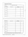
MAINTENANCE RECORD
MODEL
Recommended
mileage
FRAME SERIAL NUMBER
Workshop name
Carried out
(clock reading )
Date
900 m t.
I
1800 mt
f
3700 mt
5600 mi.
7500 mt
Recommended
mileage
Workshop name
Carried out
(clock reading)
Date
9400 mi.
11300 mi.
I
I
13200 mi.
15100 ml.
17000 mi.
18900 mi.
Detailed receipts verifying the performance 01 required maintenance should be retained .
These receipts should be transfe rred with the motorcycle to the new own er if the motorcyc le is sold.
Moto Guzzi V1000 G5 Owner’s Manual
1980 Addition
4-5
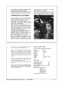
All servicing and maintenance procedures sp ecilied in the owner's manual still apply.
However, the instructions on carburation an~ idring speed adjustment are changed as lollows :
slides opening with a vacu ometer. If necessary.
adjust again the CO emiSSion.
Aller thi s, slowly and gradually turn the tw ist grip
co ntro l to sync hronize val ves o pening, chec king
on th e vacuo meter dial il in each grip posi tion
CARBURATION ADJUSTMENT
Warm the engine up to its normal riding temperature by runn ing the machine o n the road lor a
few minutes at moderate cru ising speed.
Temperatures to be reached : angine oil about
900(; (19S "F) - cylinder head (under spark plug
gasket) : about 140 0(; (285 "F).
With the machine in the neutral position, act on
screws . D~ to adjust throttle slide opening 01
each carburellor using a two-mercury column
vacuometer connected to the hole on Ihe Intake pipes, alter removing plug " P ~ .
Idling speed should be adiusted to 850-950 rpm ,
checking it with an accurate rev-counter.
Operate on screws "E .. until both exhaust pipes
emit the same amount 01 CO: 4 + 4.S G/G.
Nole • II by screwing in or out adjusters "E.. , the
idling speed adjustment should change, it w ill be
necessary to restore it to 850 - 950 rpm acting
again on screws .D~, checking always throttle
the slides have the same opening. II not, undo
locknuts . G ~ and ac t on ad justers «Fw.
Note - Belore proceeding with th e ca rburati on
adjustment, it is necessary to make sure that the
starting and riding position (.B .. and «Cw respecti ve ly) or the easy start devic e are accurately set,
adjusting any slight ollset th rough the cable
adjusters.
With the easy start lever in position « C~ , there
should be about 3 mm (.11 ") play be tween th e
cable termin al and adjusters . H.. .
II not. ad just through these, after loosening the
locknu ts.
Caution - Do not carry out any carburation adJustments belore all others have been made (ignition,
rocker clearance, etc.).
Moto Guzzi V1000 G5 Owner’s Manual
1980 Addition
Standard carburettor setting
N. 2 carburetlors «Dell'Ortow type PHF 30.
Choke
0 30 mm
Throtlle valve
50/ 3
262 ABI
Ato miser
Main jet
112
Idling jet
50
Starter jet
75
K 27 (2n d notch)
Need le
Floater
10 gr
Ignltron data
2"
Initial advance (fixed )
automatic advance
31"
lu ll advance (I. + a.)
33"
co ntact breaker gap mm 0,37 + 0,43
(.014" + .016")
spark plugs: Marelli CW 7 LP
AC44 XL
Bosch W 225 T2
Champion N 9 Y
Lodge HLNY
plug poi nts gap mm 0,6 (.023")
6-7
Moto Guzzi V1000 G5 Owner’s Manual
1980 Addition
8-9