1
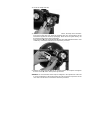
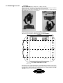
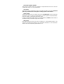
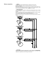
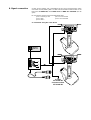
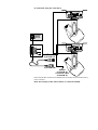
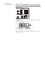
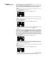
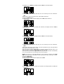
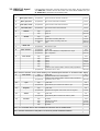
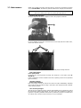
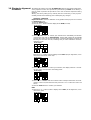
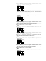
L
A
M
O
O
Z
F
C
manuale
di istruzioni
instruction
manual
1^ edizione, gennaio 1999
1st edition, january 1999
CF ZOOM AL
592 mm
750 mm
692 mm
204 mm
546 mm
514 mm
306 mm
numero di serie/serial number
data di acquisto/date of purchase
fornitore/retailer
indirizzo/address
cap/città/suburb
provincia/capital city
stato/state
tel./fax/
Prendete nota, nello spazio apposito, dei dati relativi al modello e al rivenditore del vostro CF ZOOM AL: in
caso di richiesta di informazioni, pezzi di ricambio, servizi di riparazione o altro ci permetteranno di assistervi con
la massima rapidità e precisione.
Please note in the space provided above the relative service information of the model and the retailer from
whom you purchased your CF ZOOM AL: This information will assist us in providing spare parts, repairs or in
answering any technical enquiries with the utmost speed and accuracy.
ATTENZIONE: la sicurezza dell’apparecchio è garantita solo con l’uso appropriato delle presenti istruzioni, pertanto è necessario conservarle.
WARNING: the security of the fixture is granted only if these instructions are strictly followed; therefore it is
absolutely necessary to keep this manual.
Index
1. Packaging
2. Transportation
3. Important safety information
4. Lamp: installation and replacement
5. Operating voltage and frequency
6. Mounting the unit
7. Mains connection
8. Signal connection
9. Powering up
10. DMX addressing
11. Display panel functions
12. DMX 512 channel functions
13. Aligning the lamp in the optical path
14 Moving the reset/home position by 90°
15. Replacing dichroic filters on the colour wheel
16. Automatic functions
17. Maintenance
18. Electronic alignment of motors
19. Spare parts
Authorised coemar service centres worldwide
Congratulations on having purchased a coemar product. You have assured yourself of a fixture of the highest quality, both in
componentry and in the technology used. We renew our invitation to you to complete the service information on the previous page, to expedite any request for service information or spares (in case of problems encountered either during, or subsequent to, installation). This information will assist in providing prompt and accurate advice from your coemar service centre.
1. Packaging
Following the instructions and procedures outlined in this manual will ensure the
maximum efficiency of this product for years to come.
Open the packaging and ensure that no part of the equipment has suffered damage
in transit. In case of damage to the equipment, contact your carrier immediately by
telephone or fax, following this with formal notification in writing.
packing list
Ensure the packaging contains:
1 CF ZOOM AL
1 instruction manual
1 end stop –90°
2. Transportation
The CF ZOOM AL should be transported in its original packaging or in a coemar
approved flight case.
In order to manufacture a suitable flight case, we recommend the follwing simple procedure be followed, which will stop the articulated movement of the CF ZOOM AL.
Below are illustrated the 2 diverse methods of padding which we recommend:
A) Padding around teh entire projector, including the base, with suitable padding
materials.
Polietilene
espanso/
Foam
B) Fixing the base to a rigid support, with padding surrounding the articulated head.
Polietilene
espanso/
Foam
Pomoli di
bloccaggio/
Knobs
3. Important
safety information
Fire prevention:
1. CF ZOOM AL utilises a Philips Fabolux 500W 55v; the use of any alternative
lamp is not recommended and will null and void the fixture’s warranty.
2. Never locate the fixture on any flammable surface.
3. Minimum distance from flammable materials: 0,5 m.
4. Minimum distance from the closest illuminable surface: 2 m.
5. Replace any blown or damaged fuses only with those of identical values. Refer to
the schematic diagram if there is any doubt.
6. Connect the projector to mains power via a thermal magnetic circuit breaker.
Prevention of electric shock:
1. High voltage is present in the internals of the unit. Isolate the projector from
mains supply prior to performing any function which involves touching the internals of the unit, including lamp replacement.
2. For mains connection, adhere strictly to the guidelines outlined in section 7 of this
manual.
3. The level of technology inherent in the CF ZOOM AL requires the use of specialised personnel for all service applications; refer all work to your authorised coemar service centre.
4. A good earth connection is essential for proper functioning of the projector.
Never operate the unit without proper earth connection.
5. The fixture should never be located in an exposed position, or in areas of extreme
humidity. A steady supply of circulating air is essential.
Safety:
1. The projector should alwasy be installed with bolts, clamps, and other fixings
which are suitably rated to support te weight of the unit.
2. Always use a secondary safety chaing of a suitable rating to sustain the weight of
the unit in case of the failure of the primary fixing point.
3. The external surface of the unit, at various points, may exceed 150°C. Never handle the unit until at least 10 minutes have elapsed since the lamp was turned off.
4. Always replace the lamp if any phusical damage is evident.
5. Never install the fixture in an enclosed area lacking sufficient air flow; the ambient
temperature should not exceed 35°C.
6. A hot lamp may explode. always wait for at least 10 minutes to elapse after the
unit has been turned off prior to attempting to replace the lamp.
Always wear suitable hand protection when handling the lamp.
4. Lamp: Installation
and replacement
CF ZOOM AL utilises a Philips Fabolux 500W 55V lamp with a
GX 9,5 lampbase
The lamp is available from your authorised coemar sales agent:
coemar cod.
105071
wattage
500 W
luminous flux
11.880lm
colour temperature
3200° K
base
GX 9,5
approximate life
200 hours
Attention
Turn off the power prior to opening up the unit.
The fixture’s internal temperature can reach 250° C after 5 minutes, with a maximum
peak of 350° C; ensure that the lamp is cold prior to attempting removal. The fixture
should be allowed to stand and cool for 10 minutes prior to its removal.
The lamp is part of the tungsten halogen family of incandescent lamps and must be
handled with great care. The lamp operates at high temperature, and the slight risk
of explosion of the lamp exists if operated over its recommended life of 200 hours.
We recommend, therefore, that the lamp be replaced within the manufacturer’s specified lamp life.
mounting the lamp
1) Using a 3mm hex (Allen) key, remove the two hex bolts (A) which affix the lamp
assembly to the rear of the projector.
2) Remove the lamp assembly (B).
3) Locate the lampholder (C)
4) The GX 9,5 lampholder is symmetrical in construction; the lamp used is manufactured from quartz glass and should be handled with care; always adhere to the
instructions supplied in the lamp’s packaging. Never touch the glass directly, use
the tissue provided in the lamp’s packaging.
Insert the lamp (D) into the lampholder (C). DO NOT USE UNDUE FORCE. In case
of difficulty, re-read the instructions and repeat the procedure.
5) Replace the lamp assembly (B) into its original position and replace and tighten
the two screws (A) which were previously removed.
Attention: we recommend that the lamp be realigned in the optical train of the unit
to avoid overheating of the dichroic filters and other internal components of the
unit. refer to section 13 for instructions about this procedure.
5. Operating voltage and coemar factory presets (barring specific requests), a voltage
frequency
selectable via the switch on the base of the CF ZOOM AL.
of 230v and 240v
240V
230V
main setting
coemar:
main setting
user:
coemar:
user:
115V
115V
200V
200V
208V
208V
230V
230V
240V
240V
Remember to switch the selector (230 or 240V) to the position which best matches
the average voltage available at your particular venue. The following diagrams show
the transformer settings as set by coemar.
17
18
Rosso/red 240V
Blu/blue 208V
Marrone/brown 115V
Nero/black 55V
Bianco/White
Bianco/White
Rosso/red 115 V
Giallo/yellow 208 V
Nero/black 230V
Blu/blue 240V
240V
16
Giallo/yellow 230V
13
230V
22
208V
115V
55V
115V
230V
19
208V
240V
20
If your required operating voltage is 208V, you may select this internally within the
unit by moving the cables numbered 20 and 18 (currently connected in the 240V
position) or the cables numbered 19 and 17 (currently connected in the 230V position), thereby no longer availing yourself of either the 230V or 240V option.
Giallo/yellow 230V
Rosso/red 240V
17
240V
230V
Nero/black 55V
18
Blu/blue 208V
Bianco/White
208V
16
Marrone/brown 115V
13
115V
55V
22
Bianco/White
Rosso/red 115 V
Giallo/yellow 208 V
115V
208V
20
Nero/black 230V
Blu/blue 240V
230V
240V
19
Having altered the settings as required, mark the corresponding position on the
sticker located near the on/off switch as shown in the figure below:
240V
main setting
coemar:
user:
115V
200V
208V
230V
240V
Incorrect voltage selection will detrimentally affect the operation of
the projector.Under no circumstance should you move the cables
numbered 22,16 and 13.
The operating voltage, as distinct from the input voltage, does not
need to be altered.
mounting
The CF ZOOM AL may be either floor or ceiling mounted.
The structure from which the unit is hung should be of sufficient rating to hold the
weight of the unit, as should any clamps used to hang the unit.
The structure should also be sufficiently rigid so as not to move or shake whilst the
CF ZOOM AL moves during its operation.
The mounting holes in the base of the unit allow it to be mounted at various angles
to the mounting truss and to trusses of various dimensions.
The following is a diagram outlining the base of the CF ZOOM AL.
165mm
455mm
165mm
6. Mounting the unit
n° 6 asole 72x12 mm r= 6 mm
Note that in order to take advantage of the full articulated movement of the projector, it should be installed with the label marked ” Lato frontale/ Front” facing towards
the main item to be illuminated; in this manner the “0” or “home” position of the CF
ZOOM AL will be in the most efficient position.
protection against liquids
The projector contains electric and electronic components that must not come into
contact with water, oil, or any other liquid.
movement
The projector has a movement of 370° in the base and 280° in the yoke; DO NOT
place any obstructions in the path of the projector’s movement.
safety chain
The use of a safety chain (cod. 069) - fixed to the CF ZOOM AL and to the primary
suspension point, is highly recommended to protect against accidental failure,
however unlikely, of the primary suspension point.
If using an after-market safety chain not manufactured by coemar, ensure that it is
of sufficient rating to hold the weight of the fixture.
risk of fire
Each fixture produces heat and must be installed in a well-ventilated position. The
minimum recommended distance from flammable material is: 0.5m. Minimum
distance from the object being illuminated is: 2 m.
Mains connection
cabling
The mains cable provided is thermally resistant, complying to the most recent
international standards. It meets or exceeds the VDE and IEC norms, IEC 331,
IEC 332 3C,CEI 20 35.
NB: In case of cable replacement, similar cable with comparable thermal resistant qualities must be used exclusivelly (cable 3x1.5 ø external 10 mm, rated 300/500V, tested
to 2KV, operating temperature -40° +180°, coemar cod. CV5309).
mains connection
The CF ZOOM AL can operate at voltages from 208V-230V-240V at 50 or 60Hz
(operating voltage and frequency can be selected as described in section 5 of this
manual).
Prior to connecting the unit to your mains supply, ensure that the model in your possession correctly matches the mains supply available to you.
For connection purposes, ensure your plug is of a suitable rating: 3,5 amps.
Locate the mains cable which exits the base of the unit and connect as shown
below:
marrone - brown
blu - blue
giallo/verde - yellow/green
marrone - brown
blu - blue
giallo/verde - yellow/green
marrone - brown
blu - blue
giallo/verde - yellow/green
fase
phase
neutro
neutral
massa
ground
alimentazione
main
protection
The use of a thermal magnetic circuit breaker is recommended for each CF ZOOM AL.
A good earth connection is essential for the correct operation of the fixture. Strict
adherance to regulatory norms is strongly recommended.
8. Signal connection
Control signal is digital, and is transmitted via two pair screened ø0.5mm cable.
Connection is serial, utilising XLR 3 or XLR5 male and female sockets located on the
base of the CF ZOOM AL, labeled DMX 512 and DMX 512 standard (see diagram).
Pin connections conform to the international standard:
pin 1= screening 0 volt
pin 4= not connected
pin 2= data pin 5= not connected
pin 3= data +
A connection using the 5 Pin XLR 5
out
in
Controller
Standard
DMX 512
OUT
out
3
in
2
1
Ad altri
CF ZOOM AL
Connect to other
CF ZOOM AL
B connection using the 3 Pin XLR 3
out
in
Controller
Standard
DMX 512
OUT
out
3
in
2
1
5 pin XLR 5/F
3 pin XLR 3/M
Ad altri
CF ZOOM AL
Connect to other
CF ZOOM AL
Ensure that all data conductors are isolated from one another and the metal housing
of the connector.
Note: the housing of the cannon XLR 3 or 5 must be isolated.
9. Powering up
After having followed the preceding steps, turn on the DMX 512 controller which
will be used to control the CF ZOOM AL. Following this, turn on the power to the
projector, and turn on the projector’s power switch.The projector will perform
a reset function on all the internal and external motors. This will last
some few seconds, after which it will be subject to the external signal
from the controller.
power
T 2A @ 230V
T 4A @ 115V
240V
main setting
T 5A @ 230V
T 10A @ 115V
coemar:
user:
115V
200V
208V
230V
240V
DMX led
The DMX led will be static on to indicate that DMX 512 signal is being correctly
received by the projector.
function display
DMX
+
menu enter
If the led is off, the projector is not receiving signal. check the cabling and the functioning of the controller.
10. DMX addressing
Each CF ZOOM AL utilises 13 channels of DMX 512 signal for complete control.
To ensure that each projector accesses the correct signal, it is necessary to correctly
address each fixture. Any number between 1 and 495 can be generated via the multifunction panel of the CF ZOOM AL.
This procedure myst be carried out on every CF ZOOM AL. being used
When powered up initially, each projector will show A001 which indicates DMX
address 1; a projector thus addressed will respond to commands on channels 1 to
13 from the DMX 512 controller. A second projector should be addressed as
14, a third as 27 and so on until the final CF ZOOM AL has been addressed.
Altering DMX addresses
1) Press the + or – button until the display shows the DMX required, the characters
in the display panel will flash to indicate that the selection is not stored in memory.
function display
2) Press the enter button to confirm your selection; the display will stop flashing
and the projector will now respond to the new DMX address.
3) To better understand the function of each channel, we refer you to section 12
“Control channel functions from a DMX 512 controller”.
Important Note: Keeping the + or – button pressed will cause the display to alter
at increased speed, allowing a faster selection to be effected.
By pressing the – button, you may inadvertently select a DMX address which is not
being communicated to the fixture by the controller, for example 500. If this is the
case, the display will slow the data reception, (since it does not exist), and you will note
that it is slow to respond to your commands (for example altering an address or requesting or confirming a reset). You may solve this problem by either sengin data to this
address, or by altering the incorrect DMX setting of the CF ZOOM AL in question.
11. Display
panel functions
The display panel at the rear of the CF ZOOM AL is used to display and set
function information and various parameters.
Altering the coemar factory settings may vary the functioning of the projector, causing it to not respond to external DMX 512 signal. Please read and familiarise yourself with the following information very carefully before altering any selections.
reset
This function causes a reset to occur in the case (however unlikely) that one or more
of the motors should lose its reference point.
1) Press the menu button.
2) Press the + or - button until the display shows rESE (for reset).
function display
3) Press the enter button to confirm your selection; all the motors will perform a reset.
rate
This function provides information on the speed or rate of DMX 512 signal being
received by the CF ZOOM AL.
1) Press the menu button.
2) Press the + or - button until the display shows rAtE (for rate/speed).
function display
3) Press the enter button to confirm your selection; il display visualizza un valore
numerico che è la velocità di trasmissione del segnale DMX 512.
Hour
Allows the number of hours that the fixture has been operating, or more particularly,
the number of hours that the CF ZOOM AL has been powered up to more than 10%
of its operating voltage. This number therefore is able to indicate the approximate total
number of hours that the CF ZOOM AL has been in usage. The Hour parameter is
useful, above all, in providing the user with an accurate idea of the fixture’s usage thereby allowing them knowledge of preventative servicing requirements and lamp usage
which may be useful in avoiding down time during busy periods of usage of the fixture.
1) Press the menu button.
2) Press the + or - button until the display shows HoUr (for hour).
function display
3) Press the enter button to confirm your selection; the display will show a numerical value which is the number of hours that the CF ZOOM AL has been powered
up by at least 10% of its operating voltage.
life
This function provides information on the number of hours of operation of the lamp
in the unit.
1) Press the menu button.
2) Press the + or - button until the display shows LIFE (for lamp life).
function display
3) Press the enter button to confirm your selection; the display will show a numerical value which is the length of time in hours that the lamp has been operated at
more than 10% of its operating voltage since the counter was last reset.
resetting the lamp life counter
The lamp life counter needs to be reset to zero at every lamp change to provide
accurate information on lamp life
1) Turn off the projector
2) Power up the CF ZOOM AL whilst simultaneously holding down the + and –
buttons.
3) Press the menu button.
4) Press the + or - button until the display shows LIFE (for lamp life).
function display
5) Press the enter button to confirm your selection; the display will show 0000 confirming that the counter has been reset.
disp
This function inverts the led display panels output. This allows for the display panel to
be easily read whether the unit is operated as a floor mounted fixture, or being
hung (see section 6. “Mounting the unit”).
1) Press the menu button.
2) Press the + or - button until the display shows diSP (for display).
function display
3) Press the enter button to confirm your selection; the display will show AA (for
hanging fixture installation).
function display
4) Press the + or - button the display will show
AA
(for floor mounted installation).
function display
5) Press the enter button after either step 3 or 4 to confirm your choice of display mode.
dirp
This function inverts the movement for horizontal (pan) movements.
1) Press the menu button.
2) Press the + or - button until the display shows dirP (for pan direction).
function display
3) Press the enter button to confirm your selection; the display will show cW (for
clockwise).
function display
4) Press the + or – button; the display will show ccW (for counterclockwise).
function display
5) Press the enter button after either step 3 or 4 to confirm your choice of direction.
dirt
This function inverts the movement for vertical (tilt) movements.
1) Press the menu button.
2) Press the + or - button until the display shows dirt (for tilt direction).
function display
3) Press the enter button to confirm your selection; the display will show cW (for
clockwise).
function display
4) Press the + or – button; the display will show ccW (for counterclockwise).
function display
5) Press the enter button after either step 3 or 4 to confirm your choice of direction.
oPto
This function allows the sensors which read the instantaneous pan and tilt positions
of the fixture to be switched on or off.
With the sensors activated (opto ON) the projector will automatically return to its
correct position in case it is accidentaly moved out of position.
With the sensors deactivated (opto OFF) the projector will not return automatically
to its correct position if it is accidentaly moved out of position.
NOTE: there will be a noticeable difference in the projector at startup; with opto
ON the reset procedure will take but a few seconds; the reset can last up to a minute with the opto oFF.
1) Press the menu button.
2) Press the + or - button until the display shows oPto
function display
3) Press the enter button to confirm your selection; the display will show on (opto
activated).
function display
4) Press the + or – button; the display will show oFF (opto deactivated).
function display
5) Press the enter button after either step 3 or 4 to confirm your choice.
N.B. We recommend that the opto be deactivated only if it is obviously defective
and requires replacement.
coLo
This function allows the colour wheel to be used in a proportional manner via DMX
512 signal.
1) Press the menu button.
2) Press the + or - button until the display shows coLo (for colour wheel).
function display
3) Press the enter button to confirm your selection; the display will show Strd (for standard) which corresponds to the automatic centring of the colours on the colour wheel
in the optical path of the unit. A change in the DMX 512 signal corresponds to a colour
change by the CF ZOOM AL.
function display
4) Press the + or – button; the display shows SPEc (for special) which corresponds
to the proportional selection of the colour on the colour wheel (split colours are
thereby possible)
function display
5) Press the enter button after either step 3 or step 4 to confirm your choice of colour
selection.
tESt
This function allows for a test sequence to be carried out on the respective motors of
the unit in the absence of any DMX signal.
1) Press the menu button.
2) Press the + or - button until the display shows tESt (for test).
function display
3) Press the enter button to confirm your selection; the display will show t 01 (for
test number 1). Press the + or – buttons for subsequent tests from t 01 to t 12.
function display
In these tests the projector simulates the reception of a DMX 512 signal which is
increasing from 1 to 255 on the selected channel.
t 01= movement in the X-axis
t 02= fine movement in the X-axis
t 03= movement in the Y-axis
t 04= fine movement in the Y-axis
t 05= no function
t 06= opening/closing of the blackout/strobe shutter
t 07= zoom
t 08= rotating the effects wheel including diffusor
t 09= rotating the colour wheel
t 10= cyan
t 11= magenta
t 12= yellow
t 13= no function
4) Press the enter button to confirm your selection of test to be carried out.
12. DMX 512 signal
functions
If all procedures have been correctly carried out to this point, the 13 channels of
your DMX 512 controller will have full control over all the effects available from your
CF ZOOM AL as described in the following table:
channel
function
type of control
effect
decimal
1
Base (pan) coarse
proportional
coarse control of the base movement
0-255
2
Base (pan) fine
proportional
fine control of the base movement
0-255
3
Yoke (tilt) coarse
proportional
coarse control of the Yoke movement
0-255
4
Yoke (tilt) fine
proportional
fine control of the Yoke movement
0-255
5
dimmer
step
step
6
shutter
7
lamp off
Lamp on
0-128
129-255
step
proportional
proportional
step
closed
strobe effect increasing flash rate
random strobe, increasing flash rate
open
0-9
10-127
128-247
248-255
Beam size
proportional
from flood to spot
8
filter selection
proportional
proportional
proportional
white clear
filter 1 vertical alteration of adjustable beam angle
filter 3 adjustable
0-15
16-217
218-255
9
color wheel
step
step
step
step
step
step
WHITE
color 1
color 2
color 3
color 4
0-24
25-49
50-73
74-99
100-123
124-151
proportional
color 5
continuos color wheel rotation clockwise with proportional
speed from min. to max.
0-255
152-255
NOTE: channel 9 function can be varied selecting color standard/special function on the back function display
9
color wheel
step
white clear
0- 9
proportional 360° color wheel rotation .
proportional
10- 151
continuos color wheel rotation clockwise with proportional
speed from min. to max.
proportional
152-255
10
cyan
step
proportional
white clear
proportional cyan control from white to cyan
0-9
10-255
11
magenta
step
proportional
white clear
proportional magenta control from white to magenta
0-9
10-255
12
Yellow
step
proportional
white clear
proportional yellow control from white to yellow
0-9
10-255
13
function
step
step
step
step
No effect
pan/tilt go to sensor
all motor reset
No effect
note 1: 2 or 4 numbers close to the end limit levels cannot be used as unstable levels
note 2: function channel has a delay time of 6 second to prevent accidental activation.
0-19
20-100
101-240
241-255
13. Aligning the lamp in
lamp in the optical
system
Aligning the lamp in the optical system is achieved via the 2 adjusters at the rear
of the projector.
This procedure should be undertaken to properly align the lamp in the optical
system and to avoid the possible overheating of the internal components due to the
incorrect focusing of the beam onto components not intended to be exposed to
this.
alignment procedure
Alignment is effected via the 2 adjusters A and B operating in conjunction with each
other. The lamp should be on and not dimmed, black-out fully open, and no colour
filters inserted.
If the lamp is not correctly aligned, a hot-spot will be noticeable. This is a function of
the lamp’s positioning. Use the two adjusters (A and B) to bring the hot-spot to the
centre of the beam and to flatten the beam to maximum uniformity.
vertical adjustment
Adjuster (B) acts on a lever and spring assembly to position the lamp via a vertical
movement within the reflector; rotate it until correct positioning is achieved.
horizontal adjustment
Adjuster (A) acts on a lever and spring assembly to position the lamp via a horizontal
movement within the reflector; rotate it until correct positioning is achieved.
LOOSEN
TO
RE-LAMP
Ad
Ca jus
ut
io t
n
re
-l
o
:h
a
A
B.
d
g
an mpin
ion by turning sc
re
osit
p p p. Isolate electrically be ws A
m
for
m
la t la
e
A
lamp
lamp
LOOSEN
TO
RE-LAMP
B
14 Moving the reset
home position by 90°
In the packaging for this unit coemar has supplied an optional end stop (8752.71)
which allows the reset/home position to be moved by 90°.
To replace the end stop, complete the following procedure:
1) Using a Ø 17 spanner, loosen the two bolts (A) and (B) which affix the end stop (D).
2) Without moving the yoke of the CF ZOOM AL remove the existing end stop (D).
3) Replace with the optional end stop as shown below and refasten the bolts (A).
B
B
D
D
-90°
C
A
-90°
A
C
15. Replacing dichroic
filters
Dichroic filters on the colour wheel may be replaced at will; note that any
replacements must be Ø 45mm, thickness 1.1 mm and made from tempax high
temperature-resistant glass.
Attention
Disconnect mains power prior to attempting any replacement procedure.
replacing a dichroic filter
1) Remove the inspection lid A of the projector via the two clips A as shown below.
2) Locate the dichroic colour wheel
3) Manually rotate the colour wheel until you locate the colour you wish to replace.
4) Rotate the colour wheel until you reach the empty slot.
5) Remove the dichroic filter by sliding the filter gently up and towards the central
retaining clips, thus releasing it from the two clips on the outer edge of the wheel.
6) Slide out the filter.
7) Insert the new colour filter by first sliding it under the central retaining clip, then
sliding it back under the outer clips, ensuring that it is seated correctly in the
colour wheel.
8) Replace the CF ZOOM AL inspection lid.
16. Automatic internal
functions
The CF ZOOM AL has several automatic functions and features which at first glance
may not be noticed. However, they serve to add functionality to the projector, and
to assist in extending the serviceabilty of the unit.
thermal protection
A thermal sensor in the body of the fixture protects it against overheating.
The thermal sensor operates by removing voltage to the lamp if the ambient temperature rises above a preset maximum due to either less than ideal air circulation
around the fixture or in the event of cooling fan failure.
automatic realignment
An internal 4 point encoder system allows the CF ZOOM AL to return to its correct
position in case the unit is accidentally knocked out of alignment whilst operating.
This is particularly useful if the projector is to be mounted on the floor in a position
where the performer or artist may accidentally bump the unit.
NOTE: this facility may be deactivated if desired (see section 11 ‘Display panel functions’).
17. Maintenance
Whilst every possible precaution has been taken to ensure the trouble-free operation
of your CF ZOOM AL, the following periodic maintenance is highly recommended.
Attention
Disconnect mains power prior to opening the inspection lid
Opening the projector:
The front inspection lid allows complete access to the projector’s internals.
For more detailed access to the unit remove the 4 screws (C), disconnect all 8 motor,
sensor and thermal contacts.
After this simple procedure, the whole motor assembly may be totally removed.
fuse replacement
Fuse replacement
Locate the fuse, which protects the lamp and electronics, in the base of the CF
ZOOM AL.
Using a multimeter, test the condition of the fuse, replacing it with one of equivalent
type if necessary.
periodic cleaning
lenses and reflectors
Even a fine layer of dust can reduce the luminous output substantially. Regularly
clean all lenses and the reflector using a soft cotton cloth, dampened with a specialist lens cleaning solution.
fans and air passages
The fans and air passages must be cleaned approximately every 6 weeks; the period
for this periodic cleaning will depend, of course, upon the conditions in which the
projector is operating. Suitable instruments for performing this type of maintenance
are a brush and a common vacuum cleaner or an air compressor.
periodic maintenance
lamp
The lamp should be replaced if there is any observable damage or deformation due
to heat. This will avoid the danger of the lamp exploding.
mechanicals
Periodically check all mechanical devices for wear and tear; gears, guides, belts, etc.,
replacing them if necessary. Periodically check the lubrication of all components, particularly the parts subject to high temperatures. If necessary, lubricate with suitable
lubricant, available from your coemar distributor.
electrical components
Check all electrical components for correct earthing and proper attachment of all
connectors, refastening if necessary.
18. Electronic alignment
of motors
The display panel at the rear of the CF ZOOM AL allows for the electronic alignment
of the projector’s motors. This procedure is performed by coemar at the factory. It
may be useful to perform this procedure in the case of internal components being
replaced.
Altering the factory settings may redically alter the functioning of the projector.
Carefully read all of the following prior to attempting any changes.
electronic calibration
Important Note: electronic calibration is only possible if the projector is connected
to a DMX 512 source.
1) Press the menu button.
2) Press the + or – button until the display shows rESE (for reset).
function display
3) Press the enter button to confirm your selection then immediately and simultaneously press and hold the menu button, holding both pressed for at least 30
seconds. The motors of the unit will perform a reset and the display will show the
following for some few seconds, indicating that you have entered the electronic
calibration mode:
function display
Press the + or – button until the display shows PnAL (for pan alignment, movement of the base motor of the unit).
function display
2) Press the enter button to confirm your selection; the display will show a numerical value which corresponds to the factory preset.
function display
3) Press the + or – button until the numerical value corresponds with the correct alignment of the unit (note that with each press of the + or – button the motor will
move).
4) Press the enter button to confirm your selection.
tLAL
1) Press the + or – button until the display shows tLAL (for tilt alignment, movement of the yoke).
function display
2) Press the enter button to confirm your selection; the display will show a numerical value which corresponds to the factory preset.
function display
3) Press the + or – button until the numerical value corresponds with the correct alignment of the unit (note that with each press of the + or – button the motor will
move).
4) Press the enter button to confirm your selection.
SHAL
1) Press the + or – button until the display shows SHAL (for alignment of the blackout shutter ).
function display
2) Press the enter button to confirm your selection; the display will show a numerical value which corresponds to the factory preset.
3) Press the + or – button until the numerical value corresponds with the correct alignment of the black-out shutter in the optical path of the projector.
4) Press the enter button to confirm your selection.
cYAn
1) Press the + or – button until the display shows cYAn (for alignment of the cyan
colour).
function display
2) Press the enter button to confirm your selection; the display will show a numerical value which corresponds to the factory preset.
3) Press the + or – button until the numerical value corresponds to the perfect alignment of the cyan colour in the optical path of the projector.
4) Press the enter button to confirm your selection.
MAG
1) Press the + or – button until the display shows MAG (for alignment of the
magenta colour).
function display
2) Press the enter button to confirm your selection; the display will show a numerical value which corresponds to the factory preset.
3) Press the + or – button until the numerical value corresponds to the perfect alignment of the magenta colour in the optical path of the projector.
4) Press the enter button to confirm your selection.
YELL
1) Press the + or – button until the display shows YELL (for alignment of the yellow
colour).
function display
2) Press the enter button to confirm your selection; the display will show a numerical value which corresponds to the factory preset.
3) Press the + or – button until the numerical value corresponds to the perfect alignment of the yellow colour in the optical path of the projector.
4) Press the enter button to confirm your selection.
FiAL
1) Press the + or – button until the display shows FiAL (for alignment of the beam
shaping filter effects wheel).
function display
2) Press the enter button to confirm your selection; the display will show a numerical value which corresponds to the factory preset.
3) Press the + or – button until the numerical value corresponds with the correct alignment of the beam shaping effects wheel in the optical path of the projector.
4) Press the enter button to confirm your selection.
rcoL
1) Press the + or – button until the display shows rcol (for alignment of the colour
wheel).
function display
2) Press the enter button to confirm your selection; the display will show a numerical value which corresponds to the factory preset.
3) Press the + or – button until the numerical value corresponds with the correct alignment of the colour wheel in the optical path of the projector.
4) Press the enter button to confirm your selection.
diMM
1) Press the + or – button until the display shows diMM (for dimmer preheating).
function display
2) Press the enter button to confirm your selection; the display will show a numerical value which corresponds to the factory preset.
3) Press the + or – button until you have reached a minimum level of output from
the fixture when channel 5 is at 0. This procedure allows for lamp life to be prolonged by maintaining the filament of the lamp in a state of preheating thus avoiding thermal shock to the filament.
4) Press the enter button to confirm your selection.
END
1) Press the + or – button until the display shows END (for completion of the electronic alignment procedure)
function display
2) Press the enter button to confirm your selection. The display will revert to its normal operating mode and the internal memory will record all changes made.
Important Note: At the termination of the above electronic calibration procedure,
if the END function is not performed, no memory changes will be effected. This
allows the operator to abort any changes made, in case of operator error.
19. Spare parts
All the components of the CF 1200 Hard Edge are available as replacement spares from your authorised coemar sales agent.
Accurate description of the fixture, model number, and type will assist us in providing for your requirements in an efficient and effective manner.
coemar spa
via Inghilterra
46042 Castelgoffredo (Mantova) Italy
Tel. 0376/77521
Fax 0376/780657
coemar si riserva il diritto di apportare modifiche senza preavviso.
coemar reserves the right to effect modifications without notification
manuale istruzioni
instruction manual
CF ZOOM AL
1^ edizione gennaio1999
1st edition january 1999