1
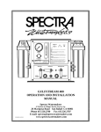
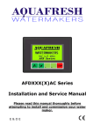
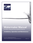
INSTALLATION MANUAL
System Diagram ................................................... Page 23
What’s Included In Your Kit .................................... Page 24
Control Panel Installation ...................................... Page 25
Pre-filter Installation ............................................. Page 26
High Pressure Pump Installation ............................ Page 27
Membrane Installation .......................................... Page 29
Seawater Lift Pump Installation ............................. Page 29
Running Tubing and Hoses ..................................... Page 30
Initial System Start-up .......................................... Page 33
Sea Clear Watermakers™ Manual - Version 1.1-G
Page 22
SYSTEM DIAGRAM
Sea Clear Watermakers™ Manual - Version 1.1-G
Page 23
WHAT’S INCLUDED IN YOUR KIT
Standard Kit (Model G-20):
Both Standard & Premium Kits:
•
(1) 40” reverse osmosis membrane with
•
(1) Control panel
housing
•
(1) Seawater lift pump
(1) 1HP 115V/230V AC pump
•
(1) Starter switch
•
(1) Pre-filter housing with wrench
Premium Kit (Model G-40):
•
(1) Pre-filter
•
(2) 40” reverse osmosis membranes with
•
25’ of high pressure tubing
housings
•
10’ of 1/4” low pressure hose
(1) 2HP 115V/230V AC pump
•
50’ of 1/2” low pressure hose
•
10’ of 3/4” low pressure hose
•
Sodium metabisulfite (pickling chemical)
•
•
Optional Features
•
Other membrane options
•
Water tester
•
Pump repair kit
•
O-ring kit for membrane housing
Items You Will Need
•
Minimum 4000 watt generator (5000 watt preferred) or larger
•
Intake through-hull
•
Brine discharge through-hull
•
Stainless steel hose clamps
•
PVC cleaner and glue
•
Membrane housing mounting brackets
Sea Clear Watermakers™ Manual - Version 1.1-G
Page 24
CONTROL PANEL INSTALLATION
►►►Prior to mounting the Control Panel, connect 1/4” hose to the Pre-filter Gauge on the back of the
Control Panel. Leave the hose loose for connection to the Pre-filter Housing later.
❶ Mount the Control Panel in a convenient location;
the panel should be easily accessible and you
should have a clear view of the gauges when
you’re running the watermaker. It should be as
close as possible to the Membrane and to the High
Pressure Pump.
►►►Make sure the panel is mounted securely to
a solid surface.
On many boats, a convenient location for the Control Panel is a cockpit locker bulkhead. This
provides easy access to controls and hose runs to the bucket are kept short.
❷ Mount the Wiring Harness near the Control Panel (but not below the panel, as it will be obscured by
hoses).
❸ Run 12-gauge wire from a dedicated 10 amp breaker to the red wire on the barrier strip.
Sea Clear Watermakers™ Manual - Version 1.1-G
Page 25
PRE-FILTER INSTALLATION
The Pre-filter Housing should be located for easy access, away
from any electronics or other surfaces that cannot get wet.
❶ Mount the Pre-filter Housing to a bulkhead using the
supplied bracket.
►►►Be sure to leave enough room below the housing to
allow for Pre-filter changes.
❷ Glue PVC fittings with PVC glue as required per your
installation.
❸ Run a 1/2” hose from the intake side of the Pre-filter Housing to the hose barb on the Control Panel
labeled “To H.P. pump.”
❹ During the Control Panel installation, you attached a 1/4” hose to the back of the Control Panel and
left it loose. Connect this hose to the 1/4” hose barb on the output side of the Pre-filter Housing.
❺ Run a 1/2” hose from the output side of the Pre-filter Housing to the input hose barb on the High
Pressure Pump.
❻ Place the 5-micron Pre-filter that was included with your kit into the Pre-filter Housing. Screw the
Pre-filter Housing back into place.
❼ The first time the Seawater Lift Pump is started or when the Pre-filter is changed, you must release
the air from the Pre-filter. Push and hold the red button on top of the Pre-filter Housing and turn on
the Seawater Lift Pump. Continue to hold the button until air stops being released. As soon as water
is seen, release the button.
Sea Clear Watermakers™ Manual - Version 1.1-G
Page 26
HIGH PRESSURE PUMP INSTALLATION
Bracket Requirements
Before installing the high pressure pump, you’ll need a bracket to mount it to the generator.
•
The pump must be mounted as level as possible with the oil dipstick on top of the unit.
•
The pump can be turned in either direction.
•
The bracket should be made of mild steel and painted prior to installation.
•
The bracket should include a method for tensioning the belt.
►►►It is recommended that a qualified metal fabricator or mechanic build and install the
bracket.
High Pressure Pump RPM
Minimum
1250
Maximum
1800
Recommended
1725
*Decreasing the RPM of the pump will simply decrease the production of fresh water.
To determine your generator’s operating RPM, refer to the AR North America chart below.
►►►Go back to page 6 and write your generator’s RPM in the gold-colored box for future reference..
Sea Clear Watermakers™ Manual - Version 1.1-G
Page 27
Once the pump has been mounted and the belt has
been installed, you’re ready to make the electrical
and plumbing connections for the High Pressure
Pump.
❶ Fill the pump with 9.81 oz. ISO 100 - NA 30 weight
hydraulic oil.
❷ Connect the [+] wire from the magnetic clutch to
the wiring harness on the Control Panel using 12-gauge tinned wire.
❸ If the generator is not grounded to the [-] terminal of the battery, you will need to run an additional
wire from the pump to your [-] battery buss. (In most cases, this will not be required.)
High Pressure Pump Fittings
See “Swagelok High Pressure Fitting Installation” on page 29.
Sea Clear Watermakers™ Manual - Version 1.1-G
Page 28
MEMBRANE INSTALLATION
The Membrane should be installed horizontally within a reasonable
distance of the Control Panel and the High Pressure Pump. When
selecting a location for the Membrane, be sure to account for the
additional space required for hose fittings.
Brine
►►►The Membrane should not be near sources of heat,
Product
Input
such as the generator or refrigeration.
The Membrane requires 2 mounting brackets. These brackets should be padded with rubber and should
be firmly, but not too tightly, clamped around the high pressure vessel.
The membrane is shipped with plugs in the end caps where the hose fittings will be installed.
Do not remove these plugs until you are prepared to install the hose. If the plugs are removed
and the membrane is allowed to dry out, you will need to purchase a replacement membrane.
SEAWATER LIFT PUMP INSTALLATION
The Seawater Lift Pump may be installed on a bulkhead with the
bracket that was included with your watermaker or it may be threaded
directly onto the through-hull fitting. If you are mounting it on a
bulkhead, the pump must be installed a minimum of 2” below the
waterline, as close to the through-hull as possible.
❶ Once the pump has been mounted, run the brown wire to the wiring
harness on the panel and run the black wire to the [-] buss.
❷ Run a 3/4” hose from the output of the Seawater Lift Pump to the
hose barb on the panel labeled “Seawater Intake.” Secure using
stainless steel hose clamps.
Sea Clear Watermakers™ Manual - Version 1.1-G
Page 29
RUNNING TUBING AND HOSES
High Pressure Tubing
Your watermaker comes with 25’ of high pressure tubing and 4 Swagelok field-attachable
fittings. If your installation will require more than 25’ of tubing, please contact us.
When planning your installation and high pressure tubing runs, be aware
that the maximum bend radius for the tubing is 12”.
►►►When running high pressure tubing in bilges or near heat sources,
it is recommended that you install 3/4” reinforced hose over the
high pressure tubing.
►►►While running tubing, you may use a heat gun to assist in bending
it. However, be very careful not to overheat an area and crimp the
tubing.
❶ Once you’ve identified where the tubing will be run, start by
running the high pressure tubing from the output port on the
High Pressure Pump to the inlet port on the membrane (see
Figure 2). Be sure when cutting the tubing to length to leave
some extra. Install end fittings per the “Swagelok High Pressure
Fitting Installation” instructions.
►►►When cutting the tubing make sure the ends are
square and clean. A plastic tubing cutter with scoring
action, which can be found in most hardware stores, is
FIGURE 2
recommended. This tool can be used to cut PVC tubing as
well. Do not use a hacksaw.
Sea Clear Watermakers™ Manual - Version 1.1-G
Page 30
❷ Blow the tubing clear to eliminate any chips or dust created by cutting.
❸ Once you’ve installed ends fittings on the high pressure tubing, connect tubing to the High Pressure
Pump and Membrane using Teflon tape to seal the threads.
❹ Install the high pressure tubing from the Membrane to the port on the Control Panel labeled “H.P.
In.” Install end fittings per the “Swagelok High Pressure Fitting Installation” instructions. Connect
and tighten fittings.
Swagelok High Pressure Fitting Installation
❶ Fully insert the tube into the fitting and against the
shoulder; rotate the nut finger-tight. Fig. 1.
High-Pressure Applications and High Safety-Factor
Systems:
Further tighten the nut until the tube will not turn by hand
or move axially in the fitting.
❷ Mark the nut at the 6 o’clock position. Fig. 2.
❸ While holding the fitting body steady, tighten the nut one
and one quarter turns to the 9 o’clock position. Fig. 3. Note:
For 1/16, 1/8, and 3/16 in.; 2, 3, and 4 mm tube fittings,
tighten the nut three-quarters turn to the 3 o’clock position.
Sea Clear Watermakers™ Manual - Version 1.1-G
Page 31
Low Pressure Hose
❶ Install a 1/2” hose run from the output of the Pre-filter Housing to the inlet
of the High Pressure Pump, securing with hose clamps.
❷ Install a 1/2” hose run from the Brine Dump port on the Control Panel to
the through-hull.
❸ Install a second hose run from the second Brine Dump port on the Control
Panel to the pressure relief valve located on the High Pressure Pump.
Though it may be necessary to “T” into another drain for the Brine discharge, it is preferable
that a new through-hull be installed specifically for the watermaker. This through-hull should
be located above the waterline and in a spot where flow can be verified from on deck.
Product Water Hose
Install a 1/2” hose run from the product port on the Membrane (see Figure 2 on page 28) to the port on
the Control Panel labeled “From R.O.M.” and secure with hose clamps.
•
Because it is important that the product water line never become blocked, we discourage
the use of shut-off valves in the product water tubing.
•
We recommend that the product water from your watermaker be connected to its own fill
on your water tank. However, as we understand this is not always possible and because all
installations are different, any solution that will not block the flow of water is acceptable.
Through-Hull (not supplied)
The boat’s designated intake through-hull should be located in an area that will always be in the water
when the boat is used under normal running conditions. This through-hull must not be located near
discharge lines that could introduce foreign materials, such as head or generator exhaust.
Sea Clear Watermakers™ Manual - Version 1.1-G
Page 32
INITIAL SYSTEM START-UP
Now that you have completed installation, you are almost ready to start the watermaker for the first
time.
Pre Start-up Checklist
□ All hose fittings are secured with hose clamps.
□ Through-hulls are open.
□ All wiring connections are secure.
□ Breaker is on.
□ Belt tension on High Pressure Pump is adjusted.
□ Verify Pressure Adjustment Needle Valve is turned counterclockwise to reduce pressure.
□ Purge Pre-filter of air by pushing and holding the red button on top of the Pre-filter Housing
and turning on the Seawater Lift Pump. Continue to hold the button until air stops being
released; as soon as water is seen, release the button.
❶ Starting with the Seawater valve in the “Seawater Intake” position and the Fresh Water valve in the
“To Flush Tank” position, place the hose labeled “To flush tank” into a clean 5 gallon bucket.
❷ Start the generator and bring it to operating temperature and RPM.
❸ Turn on the Seawater Lift Pump using the switch on the Control Panel labeled “Seawater Lift Pump.”
❹ Verify water is flowing out the Brine Dump through-hull.
►►►Take a moment to check for leaks.
❺ Turn on the High Pressure Pump using the switch on the Control Panel labeled “H.P. Clutch.”
❻ Take a moment to check for leaks again and verify additional flow through the system.
❼ Let the system run for 5 minutes and then increase the pressure by turning the Pressure Adjustment
Needle Valve clockwise until it reaches 700 psi.
❽ Do another quick check for leaks.
Sea Clear Watermakers™ Manual - Version 1.1-G
Page 33
Setting The Pressure Relief Valve
WARNING: Be sure that the High Pressure Pump needle valve is turned fully counterclockwise
to the minimum PSI.
❶ Slowly increase pressure to 950 psi by turning the Pressure Adjustment Needle Valve on the Control
Panel clockwise.
❷ Using an Allen wrench, adjust the pressure relief valve until it opens. You should see water flow into
the clear bypass hose and a slight drop in pressure on the Membrane Pressure Gauge.
❸ Reduce pressure by turning the Pressure Adjustment Needle Valve counterclockwise to operating
pressure of 850 psi.
❹ Verify output flow to 5 gallon bucket.
❺ Let system operate, discarding water for 15 minutes before testing, checking one last time for leaks.
❻ At the end of 15 minutes, fill 5 gallon bucket with product water.
Sea Clear Watermakers™ Manual - Version 1.1-G
Page 34