1
Owner's
Manual °
CRAFTSMAN
/
m
I
6 HORSEPOWER
21" POWER PROPELLED
6-SPEED
MULCHING ROTARY MOWER
Model No.
247,37638 t
/
CAUTION: Before using this
product, read this manual
and follow all Safety Rules
and Operating Instructions.
Sears,
Roebuck
Printed in U.S.A.
And Co., Hoffman
Estates,
IL 60179
USA
770-0222M
[i_
IAIA
Dlklllklt'__.
wvPInaleel_,;_,
TheCalifornia
Engine Exhaust
this birth
product
contains
chemicals
knownharm.
to the State
of
to cause from
cancer,
defects
or other
reproductive
IMPORTANT
OPERATION
PRACTICES
SAFETYAND/ORPROPERTYOF YOURSELFAND OTHERS.READAND FOLLOWALL INSTRUCTIONSIN THIS MANUALBEFORE
HIS SYMBOLPOINTSOUT
IMPORTANTSAFETYINSTRUCTIONS
WHICH,
IF NOTFOLLOWED,
COULDENDANGER
THE
ATTEMPTING
TO OPERATE"(OURLAWNMOWER.FAILURE
TO COMPLY
WITH
THESEINSTRUCTIONS
MAY RESULT
iN PERSONALA
PERSONAL
INJURY.WHENYOUSEETHIS SYMBOL-- _'E HEEDITSWARNING.
_)
_lb
DANGER:
_il.
s,e
•
•
•
•
•
•
•
•
•
•
anytype of powerequipment,carelessnessor error on the part of the operatorcan result in seriousin ury.
Yourlawn mowerwas built to be operatedaccordingto the rules forsafe operationin this manual. Aswith I
Th
s awn mower s capabe
ef amputaf ng
handsandfeet
andthrowng objects.Fa ure to observethe fo lowingsafetyinstructions
couldresultin
serious
injuryor death.
GENERAL
OPEP,__TION
Readthisownersguide carefullyin itsentirstybeforeattempting
to assemblethis machine.Read, understand,and follow all
instructionson the machineandin the manual(s) beforeoperation. Be completelyfamiliar with the controls and the proper use
of this machine before operating it. Keepthis manualin a safe
place for future and regular referenceandfor ordering replacement parts.
Your rctary mower is a precision pieceof powerequipment,nct a
plaything.Therefore,exemiseextreme caution at all times. Your
unit hasbeendesignedto perform onejob: to mow grass.Do not
use it for any other purpose.
Never allow children under 14 years old to operate a power
mower. Children 14 years old and over should only operate
mower under close parental supervision. Only responsible individuals who are familiar with theserules of safe operationshould
beallowed to use your mower.
Keepthe area of operation clearof all persons,particulady small
childrenand pets. Stop engine whenthey are in the vicinity of
your mower to helppreventbladecontactor thrown objectinjury.
Althoughthe area of operation should be completelyclearedof
foreign objects, an object may havebeen overlookedand could
be accidentallythrown by the mower in any directionand cause
serious personal injuryto the operator or anyothers allowedin
the area.
Thoroughly inspectthe area wherethe equipmentis to be used.
Remove all stones, sticks, wire, bones, toys and other foreign
objects whichcould be picked up and thrown by the mower in
any directionandcauseseriouspersonalinjury to the operatoror
anyothersallowedin the area.Planyour mowingpatternto avoid
discharge of material toward roads, sidewalks, bystandersand
the like.Tohelpavoid athrown ob ectsinjury,keepchildren,animals, bystandersand helpersat east75 feet from the mower
whileit is in operation.
_
Always wear safetyglasses with side shieldsor safety goggles RI
duringoperation or whileperforminganadjustmentor repair,to
protect eyes from foreign objectsthat may be thrown from the
machinein any direction.
Wear sturdy, rough-soledwork shoes and close-fittingslacks
and shirts.Shirts and pantsthat cover the arms and legs and
steel-toed shoes are recommended.Do not wear loose fitting
clothesor jewelry. They can be caught in moving parts. Never
operatea unit in barefeet, sandals,or sneakers.
Do not put handsor feet near or underrotating parts. Keepclear
of dischargeopening at all times as the rotating bladecancause
injury.
Many Lnjuries
occur as a result of the mower beingpulled over
the foot duringa fall. Do not hangon to the mower if you arefalling; releasethe handleimmediately.
Neverpull the mower toward you whileyou are walking.If you
must back the mower away from a wall or obstruction first look
downand behind,andthen follow thesesteps:
• Step backfrom the mowerto fufly extendyour arms.
• Besure you are well balancedwithsure footing.
• Pullthe mower backslowly, no morethan half waytoward you.
• Repeatthesesteps as needed.
2
• Do not operatethe mowerwhileunderthe influenceof alcoholor
drugs.
• Disengagethe self-propelledmechanismor driveclutchon units
soequipped beforestartingthe engine.
• The blade controlhandle is a safetydevice. Neverattemptto
bypassits operation. Doing so makesthe safetydeviceinoperative and may result in personal injury through contactwith the
rotating blade.The blade control handle must operateeasily in
bothdirections andautomaticaliy returnto the disengagedposition whenreleased.
• Neveroperatethe mower in wet grass. Alwaysbe sure of your
fooling. A slip and fall cancauseserious personalinjury.Keepa
firm hold on the handleand walk,never run. Mow onlyin daylight
or in good artificial light.
: Stopthe bladewhencrossinggravel drives, walks or roads.
If the equipment should start to vibrate abnormally, stop the
engine and check immediatelyfor the cause.Vibration is generally a warning of trouble.
• Shutthe engineoff andwaituntil the bladecomesto a complete
stopbeforeremovingthe grass catcheror uncloggingthe chute.
Thecutting blade continuesto rotatefor a few secondsafter the
engineis shut off. Neverplace any part of the body inthe blade
areauntil you are surethe bladehas stoppedrotating.
• Never operate mower without proper guards, grass catcher,
platesor othersafetyprotective devicesin place.
• Muffler and engine becomehot and can causea bum. 0o not
touch.
• Only useaccessoriesapprovedfor this rnacbinebythe manufacturer. Read,understand,andfollow all instructions providedwith
the approvedaccessory.
• If situationsoccurwhichare not coveredin this manual,usecare
andgoodjudgment. Contactyour dealerfor assistance,
II. SLOPEOPERATION
Foryoursafety,usethe slope gaugeincludedas part of this manual
to measure slopes beforeoperatingthis unit on a sloped or hilly
area.If the slopeis greaterthan 15°, as shownonthe slopegauge,
do notoperatethisuniton thatareaor seriousinjurycouldresult.
O0:
• Mow across the face of slopes; neverup and down. Exercise
extremecautionwhen changingdirectionon slopes.
• Watch for holes, ruts, hidden objects, or bumps. Tall grass can
hide obstacles.
• Always besure ot your focting. A slip andfall can causeserious
personalinjury.
DONOT:
• Doflot mow neardrop-ofts,ditchesor embankments.The operator couldloose footing or balance.
• Do not mow slopes greater than 15° as shown on the slope
gauge.
• Do not mow on wet grass. Reducedfooting couldcauseslipping.
,
• Neverrunanengineinside a closedarea.
• To reducefire hazard,keepmowerfreeof grass,leaves,or other
debris build-up.Cleanup oi]or fuel spillage.Nlow mower to cool
at least5 minutes beforestoring.
• Beforecleaning,repairing,or inspectin
O,makecertainthe blade
and all movingparts have stopped.Disconnectthe spark plug
wire,andkeepthewire awayfromthesparkplugto preventaccidentalstarting.
• Checkthe bladeandenginemounting bolts at frequent intervals
for propertightness. Also visuallyinspect blade for damage
(e.g., bent, cracked. Replacewith blade which meetsoriginal
equipmentspecifications.
• Keepall nuts, bolts, andscrewstight to be surethe equipmentis
in safe workingcondition.
• Nevertamperwith satety devices.Checktheir proper operation
regularly.
• Afterstrikinga foreign object,stopthe engine,removethe wire
from the sparkplug, andthoroughly inspectthe mower for any
damage.Repairthe damage beforestartingand operating the
mower.
• Neverattempt to make a wheelor cuttingheight adjustment
whilethe engine =srunning.
• Grasscatchercomponents
are subjecttowear,damageanddeterioration,whichcouldexposemovingpartsor allow objectsto be
thrown.Forsafetyprotection,frequentlycheckcomponentsand
replacewith manufacturer's recommendedparts, when necessary.
• Mowerblades are sharpandcancut.Wrapthe blade(s)or wear
gloves,and useextracautionwhen servicing them.
• Do not changethe enginegovernorsettingor overspendthe
engine.Excessive
engine speedsare dangerous.
Ill. CHILDREN
Tragic
accidentscanoccur if theoperatoris not alertto thepresence
of children.Children areoftenattractedto the mowerandthe mowing activity.Neverassumethat childrenwill remain whereyou last
sawthem.
• Keep childrenout of the mowing area and under the watchful
careof a responsibleadultother than the operator.
• Bealert andturn mower off if a childentersthe area.
• Beforeand whilemoving backwards,look behind and down for
small children.
•
Neverallow childrenunderage14 to operatethe mower.
Useextremecarewhenapproaching
blind comers,shrubs,trees,
or other objectsthat may obscureyour vision nf a childor hazard.
_1, _V.SERVICE
Useextreme carein handlinggasolineand other fuels. Theyare
extremelyflammableandthe vaporsare explosive.
• Useonlyanapprovedcontainer.
• Neverremovegas cap or addfuel whilethe engineis running.
Allowengineto coolat leasttwo minutesbefore refueling.
• Replacegasolinecap securelyand wipeoff any spilledgasoline
beforestartingthe engineas it may causea fire or explosion.
• xtinguish all cigarettes,cigars,pipes and other sources of ignition.
• Never refuel machine indoors becauseflammable vapors will
accumulatein the area.
• Neverstore the machineor fu_l container inside where thereis
an openflame or spark such as a gas water heater,spaceheater,
or furnace.
,_
WARNING-- YOUR
RESPONSIBILITY
Restrictthe use of this power machine to personswho read,
understandand follow the warnings and instructionsin this
manualand on the machine.
3
!!
PRODUCT
CONGRATULATIONS
on your purchase of a Sears
Craftsman Lawn Mower. It has been designed, engineered
and manufactured to give you the best possibledependability and performance+
SPECIFICATIONS
Horsepower:
Should you experience any problem you cannot easily remedy, please return the lawn mower to the nearest Sears Service Center/Department in the United States. We have
competent, well-trained technicians and the proper tools to
service or repairthis unit.
6.0
Fuel Capacity:
1-1/2 Quarts
(Unleaded)
Oil:
API Classification SF, SG or SH
Please read and retain this manual. The instructions will
enable you to assemble and maintain your lawn mower properly. Always observe the "SAFETY RULES."
Spark Plug (Gap .030 in.):
Champion J19LM
(or Equivalent)
Blade Bolt Torque:
MODEL
NUMBER 247.376380
SERIAL
NUMBER
DATE OF
PURCHASE
MAINTENANCE
SHOULD
RECORD
BOTH
SERIAL
AGREEMENT
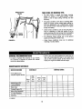
WARNING: This unit is equipped with an internal combustion engine and should not be used on or near any unimproved forest-cevered, brush-covered or grass-covered land
unless the engine's exhaust system is equipped with a spark
arrester meeting applicable local or state laws (if any). If a
spark arrester is used, it should be maintained in effective
working order by the operator.
NUMBER
AND DATE OF PURCHASE
AND KEEP IN A SAFE
PLACE FOR FUTURE REFERENCE.
CUSTOMER
450-600 in. Ibs.
A Sears Maintenance Agreement is available on this product.Contact your nearest Sears store for details.
THE MODEL
AND SERIAL NUMBERS
WILL BE
FOUND ON A LABEL ATIACH ED TO THE TOP REAR
OF THE DECK.
YOU
27 Ounces
SAE 30
RESPONSIBILITIES
In the State of California the above is required by law (Section 4442 of the California Public Resources Code). Other
states may have similar laws. Federal laws apply on federal
lands. A spark arrester for the muffler is available through
your nearest Sears Authorized Service Center. (See the
REPAIR PARTS sectionof this manual.)
• Read and observe the safety rules.
• Follow a regular schedule in maintaining, caring for and
usingyour lawn mower.
• Follow the instructions under =Customer Responsibilities"
and =Storage" sections of this Owner's Manual.
FULLTWO YEARWARRANTYON CRAFTSMANLAWN MOWER
For two years from the date of purchase, when this Craftsman lawn mower is maintained, lubricated, and
tuned up according to the operating and maintenance instructions in the operator's manual, Sears will repair,
free of charge, any defect in material or workmanship.
This warranty excludes the blades, blade adapters, belts, air cleaners and spark plugs, which are expendable
parts and become worn during normal use.
If this lawn mower is used for commercial
date of purchase.
or rental purposes,
this warranty
WARRANTY SERVICE IS AVAILABLE BY CONTACTING
THE NEAREST
THE UNITED STATES. THIS WARRANTY APPLIES ONLY WHILE THIS
UNITED STATES.
This warranty
state.
gives you specific
applies for only 30 days from the
SEARS SERVICE CENTER IN
PRODUCT IS IN USE IN THE
legal rights, and you may also have other rights which vary from state to
SEARS ROEBUCK
AND CO., DEPT. 817WA, Hoffman
4
Estates, IL 60179
SAFETY RULES ..........................
PRODUCT SPECIFICATIONS .................
WARRANTY ...............................
INDEX ....................................
MOWER ACCESSORIES .....................
ASSEMBLY ..............................
OPERATION ............................
MAINTENANCE .........................
A
Accessories .....................
5
Adjustments:
Carburetor ....................
15
Cutting Height ..................
8
Engine Speed .................
15
Handle Height ..............
13, 14
Air Filter .......................
12
Assembly .....................
6, 7
B
Belt Removal and Replacement.....
15
Blade:
Replacement ..................
1!
Sharpening ...................
11
C
Controls:
Blade Control Handle .............
7
Engine Speed Control ..........
.. 7
Cleaning ......................
• 12
Customer Responsibilities .........
10
Cutting Height ...................
8
D
Deflector, Side Discharge ..........
7
Drive Clutch Adjustment ..........
14
E
Engine:
Lubrication ...................
• 12
Speed Control ................
..8
Starting .....................
.. 9
Storage .....................
• 13
F
Filter, Air ......................
• 12
2, 3
4
4
5
5
6, 7
7-10
10-12
SERVICE AND ADJUSTMENT ..............
STORAGE ................................
TROUBLE SHOOTING ......................
PARTS ORDERING/SERVICE ................
REPAIR PARTS--MOWER .................
REPAIR PARTS--ENGINE .................
SLOPE GAUGE ...........................
G
Gasoline:
Storage .......................
Tank Capacity ...................
Type ..........................
H
Handle:
Height Adjustment............
Storage .......................
13
9
9
13, 14
13
L
Lubrication:
Brake Spring Bracket ............
Engine........................
Wheel Adjusters ................
Wheels .......................
M
Maintenance:
Agreement .....................
Air Filter .......................
Blade Care/Replacement .........
Engine ........................
Lubrication ...................
Spark Plug ...................
Schedule ......................
Mulching and Mowing Tips .........
Mulching Plug ....................
O
Oil:
Change .......................
Storage .......................
Type .......................
Operating Mower ...............
11
12
11
11
4
12
11
12
t2
12
10
10
7
12
13
8,!1
7-10
13-15
15
16
17
18-20
21-24
25
P
Primer ..........................
9
R
RepairlReplacement Parts ......
18-24
Responsibilities, Customer ......
10-12
Rope Guide .....................
6
S
Safety Rules ...................
2, 3
Service and Adjustments:
Blade ........................
11
Carburetor ....................
14
Cutting Height ...................
8
Engine .......................
12
Handle Height ...............
13, 14
Rear Trail Shield ................
t4
Service Recommendations ........
t0
Side Chute Deflector ..............
7
Spark Plug .....................
12
Specifications ....................
4
Starting the Engine ................
9
Stopping the Mower ...............
8
Storage ........................
15
T
Table of Contents .................
5
Trouble Shooting Guide ...........
16
W
Warranty ........................
4
Wheels:
Adjusting Height .................
8
Lubrication ....................
11
These accessories were available when the mower was purchased. They are also available at most Sears retail
outlets, catalog and service centers. Most Sears stores can order repair parts for you, when you provide the model
number of your mower•
ENGINE
Spark
Plug
Air
Filter
MOWER
I GasCsn
iStab,,,ze
Muffler
Grass Catch*
i I--_I
I
I_
i
L--,
MOWER MAINTENANCE
Blade
Wheels
Retaining
Post
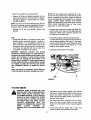
IMPORTANT: This unit is shipped WITHOUT GASOLINE or OIL in the engine. Be certain to service
engine with gasoline and oil before operating your
mower.
Plug
NOTE: Reference to right or left hand side of the
mower is observed from the operating position.
TO REMOVEMOWERFROMCARTON
Remove staples,break glue on top flaps, or cut tape
at carton end and peel alongtop flap to open carton.
• Remove loose parts included with unit (owner's
manual, side discharge chute, grass catcher
bracket and bottle of oil).
• Cut along dotted lines and lay carton down flat.
• Remove packing material.
• Roll or slide unit out of carton. Check carton thoroughly for loose parts.
NOTE: Keep the grass catcher bracket in a safe place.
ff you purchase the optional grass catcher, mount the
bracket on the right side of the upper handle as shown
on page 18 of this manual, key 10.
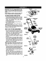
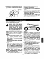
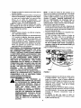
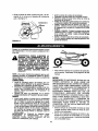
HOWTO SET UP YOURLAWNMOWER
• Disconnectthe spark plug wire from the spark plug.
Ground the spark plug wire by attaching it to the
retaining post until ready to operate your mower.
See figures 1 and 2. (Spark plug wire is shown in
figure 1 without the rubber boot for clarity.)
• Remove any packing material which may be
between the upper and lower handles for shipping
purposes.
• Pull up and back on the upper handle to raise the
handle into the operating position. Make certain the
lower handle is seated securely into the handle
mounting brackets. Tighten the hand knobs on
each side of the handle (carriage bolts must be
seated properly into the handle).
NOTE: Your mower is shipped with the handle in the
higher height position, ff you wish to lower the height
of the handle, refer to the Adjustment Section at this
time.
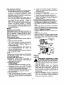
• Using a pair of pliers, remove hairpin clips from the
outer hole in weld pins on handle mounting brackets.
Place hairpin clipsin the inner hole. See figure 3.
• The rope guide is attached to the right side of upper
handle. Loosen the wing nut which secures the
rope guide. See figure 4.
• With the spark plug wire disconnected and
grounded, hold the blade control handle against the
upper handle, and pull the starter rope out of the
engine. Release the blade control handle. Slip the
starter rope into the rope guide. Tighten the wing
nut.
Spark Plug
Wire
FIGURE 1.
Handle
Handle
Rope
Guide
Starter
Rope
Handle
Spark Plug
Mounting
Bracket
Boot
Mulchinc
Plug
FIGURE 2.
\\
ewer\\
M"o"u".; eg
Srackst
I,_
Hairpin \ _
_Waid
Rll
| _
Pin
FIGURE 3.
Wing Nut
Guide
Starter
Rope
FIGURE 4.
_ Inner
\k/Hole
• Makecertainall
nuts and bolts are tightened
securely. Also, be certain to reconnect the spark
plug wire before starting the mower.
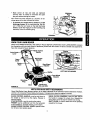
Mulching
Plug
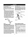
Your mower has been shipped as a mulcher. To discharge grass to the side, proceed as follows.
Hooks
• To convert your mower from a mulcher to a side
discharge mower, lift the mulching plug. See figure 5. Slide the two hooks on the side discharge
deflector under the hinge pin on the mulching plug
assembly. Lowerthe mulching plug.
FIGURE 5.
KNOWYOUR LAWNMOWER
READ THIS OWNER'S MANUAL AND SAFETY RULES BEFORE OPERATING YOUR LAWN MOWER. Compare
the illustrations with your lawn mower to familiarize yourself with the location of various controls and adjustments.
Save this manual for future reference.
Drivq
Lever
line
Handle
Oil Fill and
Guide
Rope
Rear Wheel
uster
Primer
LEFT SIDE OF MOWER
Muffler
Adjuster
Mulchin_
Plug
FIGURE 6.
Spark Plug
Wire and Boot
MEETSCPSCBLADESAFETYREQUIREMENTS
Sears Walk-Behind Lawn Mowers conform to the safety standards of the American National Standards Institute,
and the U.S. Consumer Product Safety Commission,The blade turns when the engine is running.
BLADE CONTROL HANDLE--must be held down to
the handle to start and run the engine. Release to
stop the engine.
STARTER ROPE--used for starting the engine.
PRIMER-pumps additional fuel from the carburetor
to the cylinder for use when starting a cold engine.
ENGINE SPEED CONTROL LEVER--permits selection of fast or slow engine speed,
DRIVE CLUTCH CONTROL--must be held against
the handle to engage the wheel drive. Release the
drive clutchcontrolto stop the wheels from driving.
SHIFT LEVER--is used to select one of six operating
speeds for the mower.
7
BEFORE USING YOUR LAWN MOWER, AGAIN REFER TO THE "SAFETY RULES" AS SHOWN ON PAGE 2 OF
THIS MANUAL. ALWAYS BE CAREFUL.
The operation of any lawn mower can result in foreign objects being thrown into the eyes,
which can result in severe eye damage. Always wear safety glasses or eye shields before
starting power tool operation or while performingany adjustments or repairs.We recommend Wide Vision Safety Mask for over spectacles or standard glasses available at Sears
Retail or Catalog Stores.
HOWTO USEYOURMOWER
ADJUST cu'n'ING HEIGHT
The height adjuster levers for the wheels are located
on the left side of the deck. See figure 6. The levers
may be placed in one of nine cutting height positions.
Both levers should always be set to the same position.
TO STOP ENGINE
Release blade control handle to stop engine. Disconnect the spark plug wire and move it away from the
spark plug to prevent accidental starting while equipment is unattended.
•
ENGINE SPEED CONTROL
The engine speed is controlled by a lever (red knob)
located on the left side of the engine.The "HI" position
is for starting engine, normal cutting and best performance. The "LOW" position is for light cutting, trimming and fuel economy.
Raise wheels for low Cut and lower wheels for high
cut.
• To change cutting height, move adjuster levers
toward wheels. Move wheels up or downto suit your
requirements. Be sure both levers are in the same
setting.
• Adjust cutting height to suit your requirements.
Refer to the =Mulching or Mowing Tips"on page 10.
(The height adjusters may seem hardto move when
new.They will operate easier after some use.)
BLADE CONTROL HANDLE
Your mower has a control handle which requires the
operator to be behind the handle to start and run the
mower. When the operator releases the control handle, the engine will stop and an internal brake helps
the blade to stop quickly.
When the operator leaves the operating position to
change the cutting height, pick up sticks or other
objects in the way, the engine will stop automatically
when the controlhandle is released.
BEFORESTARTINGENGINE
OIL
A 27 ounce bottle of SAE 30 oil is included with your
new lawn mower.
DRIVE CLUTCH CONTROL LEVER
To engage the wheel drive, squeeze the drive clutch
control lever against the handle. Releasing the drive
clutch control lever stops the wheels from driving.
Release the drive clutch control lever to slow down
when negotiating an obstacle, making a turn or stopping.
Only use high quality detergent oil rated with API service classification SF, SG or SH. Select the oil's viscosity grade according to your expected operating
temperature.
Colder
SHIFT LEVER
The six speed shift lever is located below the drive
clutch control lever. Position 1 is the slowest speed;
position 6 is the fastest. Release the drive clutchcontrol lever when changing speeds.
32 °
Warmer
NOTE: Although multi-viscosity oil (5W30, 10W30,
etc.) improve starting in cold weather, these multiviscosity oils will result in increased oil consumption
when used above 32°F. Check your oil level more frequently to avoid possible engine damage from running
low on oil.
IMPORTANT: Move the shift lever ONLY when the
engine is running. Shifting the speeds with the
engine off can cause damage to the unit.
8
• Place unit so engine is in a level position.
• Remove oil fill cap and dipstick assembly. Pour oii
slowlyuntil oil level is to the FULL mark on dipstick.
Crankcase capacity is approximately 27 ounces.
DO NOT OVERFILL.
NOTE: Crankcase oil should be changed after first two
(2) hours of operation and every twenty-five (25) hours
thereafter. Refer to ENGINE LUBRICATION section.
NOTE: The drive cable has been adjusted at the factory with the unit in sixth speed. If the drive slipswhen
mower is operated in first speed, tighten the cable by
moving the adjustment wheel away from the operator
slightly. ALWAYS MAKE CERTAIN THE MOWER
DOES NOT DRIVE WITH THE DRIVE CLUTCH CONTROL LEVER RELEASED. Refer to "Drive Clutch
Adjustment" for further information.
• Replace oil fill cap and dipstick. Tighten cap
securely.
Connect spark plug wire to spark plug. Make certain the metal cap on the end of the spark plug wire
(inside the rubber boot) is fastened securely over
the metal tip on the spark plug.
GAS
• Fill gas tank with about 1-1/2 quarts of clean, fresh,
lead-free grade automotive gasoline. Low-lead or
regular gasoline is an acceptable substitute. DO
NOT use Ethyl or high octane gasoline. Be certain
container is clean and free from rust or foreign particles. Never use gasoline that may be stale from
long periods of storage in the container.
Press primer button as follows (cold starts only).
For each initial start, push primer button three t_mes
prior to starter operation. See figure 7. Use sharp
pushes, wait between each push. Repeat the above
for each starter operation as necessary. Do not use
primer for warm engine restarts.
• Set engine speed controlto "HI"speed.
WARNING: Experience indicates that alcohol
blended fuels (called gasohol or using ethanol or
methanol) can attract moisture which leads to separation and formation of acids during storage.
Acidic gas can damage the fuel system of an
engine while In storage. To avoid engine problems,
the fuel system should be emptied before storage
for 30 days or longer. Use fresh fuel next season.
See "STORAGE" Section for additional information.
Engine Speed
Lever
Never use engine or carburetor cleaner products
in the fuel tank or permanent damage may occur.
/
/
/
LOW
\
HI
FIGURE 7.
TO STARTENGINE
FOR THE FIRST TIME, PLACE MOWER IN
WARNING:
WHEN STARTING THE UNIT
FIRST SPEED (SLOW) POSITION.
FACE
THE MOWER AGAINST A SOLID OBJECT
SUCH AS A WALL, FENCE, ETC. START
THE UNIT, AND IF IT SHOWS ANY SIGNS
OF MOTION WITH THE DRIVE CLUTCH
CONTROL
DISENGAGED,
SHUT
THE
ENGINE OFF IMMEDIATELY. ADJUST THE
DRIVE
CLUTCH
CONTROL
AS
INSTRUCTED
IN THE ADJUSTMENT
SECTION.
Hold blade control handle against upper handle.
See figure 8. Grasp starter handle and pull rope out
slowly until engine reaches start of compression
cycle (rope will pull slightly harder at this point). Let
the rope rewind slowly.
Pull rope with a rapid, continuous,full arm stroke.
Keep a firm grip on start handle. Let rope rewind
slowly.Do not let starter handle snap back against
starter.
If after three pulis the engine fails to start, push
primer five times, then pull starter rope again.
Blade Control
Handle
MULCHINGORMOWINGTIPS
• For best results in normal and heavy mowing,
always run engine in "HI" speed position. "LOW"
speed is only for light cutting, trimming and fuel
economy.
• The grass condition at the time of mowing determines the proper mower cutting height setting for
best lawn appearance. For a healthy lawn, always
cut one-third or less of the total length of the grass
at any one cutting.
• Under certain conditions, such as very tall grass, it
may be necessary to raise the height of cut to
reduce pushing effort and to keep from overloading
the engine and leaving clumps of grass clippings.
Starter
- Handle
• For extremely heavy cutting, use a slow ground
speed, and reduce the width of cut.
FIGURE 8.
• Under heavy conditions cross cut for additional
mulching of surface debris.
GENERALRECOMMENDATIONS
• Once a year you should replace the spark plug, air
filter, and check blade for wear. A new spark plug
and air filter assures proper air-fuel mixture and
helps your engine run better and last longer.
• In order to maintain the warranty on your mower,
the customer is expected to perform the maintenance as outlined below.
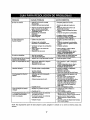
MAINTENANCESCHEDULE
SERVICERECORD
SERVICEDATES
SCHEDULE
Fill in dates as you
complete regular service
Every
Use
Check Engine Oil
After
First
Two
Hours
Every
25
Hours
q
q
q
q
Every
100
Hours
q
Lubricate Mower
Blade Care
Change Engine Oil
Spark Plug Replaced
q
Air Filter Replaced
Cleaning
q
CHECK
10
LUBRICATION
• Remove the bolt and blade bell supportwhich hold
the blade and adapter to the engine crankshaft.
Remove the blade and adapter from the crankshaft.
ENGINE OIL RECOMMENDATIONS
A 27 ounce bottle of SAE 30 oil is included with your
new lawn mower.
Only use high quality detergent oil rated with API service classificationSF, SG or SH. Select the oil's viscosity grade according to your expected operating
temperature.
Colder
_
32°
5W30
_
Blade Adapter-----.-_
_pport
Warmer
SAE 30
To reinstall blade:
• Be sure to installthe blade with the side of the blade
marked "Bottom"(or with part number) facing the
ground when the mower is in the operatingposition.
• Be certain the blade is aligned with and seated onto
the blade adapter flanges.
• Place blade bell support on blade. Make sure the
notches on the blade bell support are aligned with
the small hole in the blade.
• Replace hex bolt.
NOTE: Although multi-viscosity oil (5E30, 10W30,
etc.) improves starting in coldweather, these multi-viscosity oils will result in increased oil consumption
when used above 32° F. Check your oil level more frequently to avoid possibleengine damage from running
low on oil.
WHEELS
DO NOT oil or grease the wheel bearings. Viscous
lubricantswill attractdust and dirt that will shorten the
life of the self-lubricatingwheel bearings. If you feel
the wheels must be lubricated, use only a dry, silicone
type lubricantsparingly,
Spacer-_
PULLEY
WHEEL ADJUSTERS
For easy operation, lubricate the wheel adjusters at
least once a season with light oil.
BRAKE SPRING BRACKET
Spray a light oil lubricant on the brake spring bracket,
located on the right rear corner of the engine, at least
once a season.
Spacer----_-l_
Wave
Washer
_)
I
• Make sure to follow the correct order of hardware
and pultey set-up. When reassembling, place the
spacer on the crankshaft first, then the wave
washer.
• Tighten bolt to torque: 450 in. Ibs. min., 600 in. Ibs.
max.
IMPORTANT: THE BOLT USED TO SECURE THE
BLADE TO ENGINE IS SPECIALLY HEAT-TREATED.
DO NOT SUBSTITUTE (SEE REPAIR PARTS).
TRANSMISSION
The transmission is pre-lubricated and sealed at the
factory.It does not require checking. If disassembled
for any reason, fill with 2 ounces of Alvania grease,
part number 737-0168.
MOWER
BLADE CARE
Yourmower will work better with a sharp blade.
&
-*----..-- Hex Bolt
FIGURE 9.
CAUTION: DISCONNECT SPARK PLUG
WIRE FROM SPARK PLUG AND PLACE
WIRE WHERE IT CANNOT COME IN CONTACT WITH THE SPARK PLUG.
_11
DANGEROUS AND MAY MAKE THE
CAUTION:
A LOOSE
BLADE CAN BE
ENGINE HARDTO
START.
Use only a Sears authorized replacament blade to get
the best cutting results.
TO REMOVE BLADE (See Figure 9):
• Turn mower on its side. Make sure air filter and carburetorare up.
• Use a block of wood between blade and mower
deck to prevent blade from turning when bolt is
removed. Protect your hands with gloves and/or
wrap blade with heavy cloth.
NOTE: We do not recommend sharpeningthe blade-but ifyou do, be sure blade is balanced.
TO SHARPEN BLADE
• The blade can be sharpened with a file or on a
grinding wheel. Do not attempt to sharpen while on
the mower,
11
• Care should be taken to keep the blade balanced.
An unbalanced blade will cause excessive vibration
when running and eventual damage to mower and
engine.
• To check blade balance, drive a nail into a beam or
wall. Leave about one inch of the straight nail
exposed. Place center hole of blade over the head
of the nail. If blade is balanced, it should remain in a
horizontal position. If either end of the blade moves
downward, blade is not balanced. Sharpen the
heavy end until the blade is balanced.
ENGINE
ENGINE LUBRICATION
You must change the oil in the crankcase after the first
two (2) hours of operation and after each 25 hours of
use thereafter. CHANGE THE OIL MORE FREQUENTLY IF USED IN SANDY OR DUSTY CONDITIONS.
• Wrap in a clean cloth and squeeze (don'ttwist) until
completely dry.
• Saturate with engine oil and squeeze (don'ttwist) to
distributeoil and remove excess oil.
B. TO REMOVE AND INSTALL FILTER:
• Remove cover from body by looseningcover screw.
Do not remove screw from cover.
• Swing cover downto remove from hinge.
• Inspect filter for discolorationor dirt accumulation.If
either is present, service per preceding "TO SERVICE FILTER" instructions.
• Clean inside of body and coverthoroughly.
• Install filter in body.
• Install cover on body by aligning hinge between
body and cover. Swing cover upward against body.
Tighten cover screw securely.
Screw
TO DRAIN OIL
• Disconnect spark plug wire from spark plug and
place wire where it cannot come in contact with
plug.
• Drain the gas tank.
• Remove the oil fill cap and dipstick.Turn and tip the
unit on its side with the carburetor up, and drain oil
into a suitable container.
Refill crankcase with oil. Refer to "ENGINE OIL
RECOMMENDATIONS" on previouspage.
• Replace oil fill cap and dipstick. Tighten cap
securely.
Filter
Cover
Hinge
FIGURE 10.
CLEANING
SPARK PLUG
Change your spark plug each year to make your
engine start easier and run better. Set spark plug gap
at .030 inch.
WIRE FROM SPARK PLUG AND PLACE
WARNING:
DISCONNECT
SPARKIN PLUG
WIRE WHERE
IT CANNOT COME
CONTACT WITH THE SPARK PLUG.
• Turn mower on its side with carburetor and air filter
up.
• Clean the underside of your mower after each use
by scraping to remove build-up of grass clippings,
leaves, dirt or other matter, if this debris is allowed
to accumulate, it will invite rust and corrosion, and
may prevent proper mulching.
• Clean your mower and engine often to keep buildup of grass or debris from accumulating around
engine. A clogged engine runs hotter and shortens
engine life.
NOTE: We DO NOT recommend usinga garden hose
to clean mower unless the electrical system, muffler,
air filter and carburetor are covered to keep water out.
Water in engine can result in shorteningengine life.
,_
AIR FILTER (See Figure 10)
IMPORTANT: NEVER RUN ENGINE WITHOUT
COMPLETE
AIR CLEANER
INSTALLED ON
ENGINE.
A. TO SERVICE FILTER:
PAPER FILTER:
Do not attemptto clean or oil tilter.
• Replace once a year or every 100 operating hours,
more often if used in extremely dusty conditions.
• Replacement filters are available at any Authorized
Sears Service Outlet.
FOAM FILTER (if so equipped):
Clean and re-oil every throe (3) months or every 25
operating hours, Clean and re-oil daily if used in
extremely dusty conditions,
• Wash in water and detergent solution and squeeze
(don't twist) until all dirt is removed.
• Rinse thoroughlyin clear water.
12
CuI-rlNG HEIGHTADJUSTMENT
If the mower does not drive in low speed, tighten the
cable by turning the adjustment wheel away from the
operator. Recheck the adjustment.
Refer to "ADJUST CUFFING HEIGHT" in operation
section of manual.
Periodic adjustment may also be necessary due to
normal stretch and wear on the belt. Adjustment may
be needed if the wheels seem to hesitate, but the
engine maintains the same speed. To tighten the
cable, move the adjustment wheel toward the right.
Always be certain to recheck the adjustment.
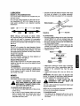
HANDLEHEIGHTADJUSTMENT
Your mower is shipped w_ththe handle in the higher
height position. To lower the handle height, proceed as
foltows.
• Remove the starter rope from the rope guide.
• Remove the upper handle by removing the hand
knobs and carriage bolts. Lay the upper handle out
of the way, being careful not to bend or kink the
cable.
• Remove the hairpin clips from the weld pins on the
handle brackets. Press outward on the sides of the
lower handle, and remove it from the mower.
• Turn the lower handle around so the notch on the
bottom of the lower handle is facing forward as
shown in figure 11. Reassemble, placing the bottom
holes in the handle over the weld pins in the handle
mounting bracket.
• Reassemble the upper handle.
• Place the hairpin clips in the inner holes in the weld
pins and attach the starter rope as instructed in the
Assembly Section.
®
BOTTOM
VIEW
Loosen
Tighten
Lower
_
FIGURE 12.
Handle --_.
teh
FIGURE 1I.
DRIVECLUTCHADJUSTMENT
SIX SPEEDSHIFTADJUSTMENT
The correct drive clutch adjustment varies with the
speed of the mower. The drive clutch adjustment may
be checked as follows. Without starting the engine,
engage the ddve clutch control (squeeze control lever
against the handle) and pull the mower backward. The
wheels should lock. Then release the drive clutch control and pull the mower backward. It should move
freely (or with only a small amount of resistance).
Periodic adjustment may be required due to normal
wear. Adjustment is needed if the shift lever cannot be
moved to all six positions.
• Loosen the nut which secures the adjustable cable
bracket, located on the left side of the engine. See
figure 13.
Place the shift lever in high speed (6) position.
Move the bracket to make certain it is loose. Then
slide it towards the rear of the unit as far as it willgo,
so that the pulley halves (beneath the deck) are
against each other. Make certain the belt does not
interfere.
If the wheels lock up when pulled backward with the
drive clutch control released (engine off), or if mower
moves forward with the drive clutch control released
(engine running), turn the adjustment wheel, located
beneath the drive clutch control housing, toward the
operator to loosen the cable. See figure 12. Recheck
the adjustment as instructed above.
•
13
Tighten the nut to secure the bracket
tion.
in this posi-
Self-Tapping
Screws
Adjustable
Cable Bracket
; Speed
Cable
FIGURE 13.
Tmnsmisslon
Belt Cover
Self-Tapping
Screws
FIGURE 14.
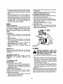
• Tip the mower on itsside. Block securely.
• Remove the center bolt which secures the blade to
the crankshaft. See figure 15. Remove the blade
and blade adapter.
Lower Pulley
CARBURETOR
The carburetor on your lawn mower has been completely adjusted at the factory. If your engine does net
operate properly due to suspected carburetor problems, take your mower to an authorized Sears Service
Center for repair and adjustment,
Self-Tapping
Screws
ENGINESPEED
The engine slow and fast speeds have been set at the
factory. Do not attempt to increase engine speed or it
may result in personal injury. If you believe that the
engine is running too fast or too slow,take your mower
to an authorized Sears Service Center for repair and
adjustment.
Center
Bolt
FIGURE 15.
• Remove the two-self-tappingscrews which secure
the lower pulley half. See figure 15. Rotate the
lower pulley half 90° clockwise(see figure 16) and
remove from the mower. Remove the belt from
around the crankshaft.
REARTRAILSHIELD
The rear trail shield,attached between the rear wheels
of your mower, is provided to minimize the possibility
that objects will be thrown out the rear of the mower
toward the operator.
If the shield is damaged, it shouldbe replaced.
j
Lower Pulley _,(3
Half
/
,/
BELT REMOVALAND REPLACEMENT
(
• Place shift lever in third speed.
• Disconnect the spark plug wire and ground it
against the engine.
• Drain the fuel tank or place a piece of plastic
beneath the cap to prevent gasoline leakage.
• Remove the transmission belt cover by removing
five self-tapping screws. See figure 14.
FIGURE 16.
14
Pin
• Remove
thebelt from
between the idler pulley and
the belt guard on the idler pulley bracket. See figure
17.
• Remove the belt from the transmissionpulley.
• Assemble the new belt as follows.
• Push the idler pulley up out of the way as shown in
figure 17.
• Slide the belt in from the rear of the deck, and place
it around the transmissionpulley.
• Release the idler pulley so it falls down into position.
Slide the belt in between the idler pulley and belt
guard on the idler pulley bracket.
• Grease the crankshaft. Place belt between the two
pulley halves, and reassemble the blade adapter
and blade. Reassemble the inside belt cover.
• Reassemble the transmissionbelt cover.
Idler Pulley
Guard
FIGURE 17.
Prepare your mower for storage at the end of the season or it the unit will not be used for 30 days.
WARNING: NEVER STORE MACHINE
WITH FUEL INTHE FUELTANK INSIDE OF
BUILDING WHERE FUMES MAY REACH
AN OPEN FLAME OR SPARK, OR WHERE
IGNITION
SOURCES ARE PRESENT
SUCH AS HOT WATER AND SPACE HEATERS, FURNACES, CLOTHES DRYERS,
STOVES, ELECTRIC MOTORS, ETC.
FIGURE 18.
NOTE: A yearly check-up by your local Sears Service
Center is a good way to make certain your mower will
provide maximum performancefor the next season.
MOWER
• Clean underside of mower housing (See "CLEANING" in "Customer Responsibilities" section of
manual).
• Inspect and replace/sharpen blade, if required (See
"BLADE CARE" in "Customer Responsibilities"
sectionof manual).
• Lubricate as shown in "Customer Responsibilities"
section of manual.
HANDLE
• You can fold your mower's handle for storage as
shown in figure 11. Remove the starter rope from
the rope guide. Loosen the two hand knobs on the
sides of the handle, and let the upper handle fold
down to the rear. Move the haJrpinclipsto the outer
hole in the weld pins on the handle mountingbrackets. Refer to figure 3. Spread the sides of the lower
handle, and push it forward and down.
IMPORTANT: WHEN FOLDING HANDLE FOR
STORAGE OR TRANSPORTATION, BE CAREFUL
NOT TO BEND OR KINK THE CABLES.
• To place the handle in the operating position, refer
to "Assembly" on page 6 of this manual.
15
IMPORTANT: IT IS IMPORTANT TO PREVENT GUM
DEPOSITS FROM FORMING IN ESSENTIAL FUEL
SYSTEM PARTS SUCH AS CARBURETOR, FUEL
FILTER, FUEL HOSE, OR TANK DURING STORAGE.
ALSO, FUEL (CALLED GASOHOL OR USING ETHANOL OR METHANOL) CAN ATTRACT MOISTURE
WHICH LEADS TO SEPARATION AND FORMATION
OF ACID DURING STORAGE. ACIDIC GAS CAN
DAMAGE THE FUEL SYSTEM OF AN ENGINE
WHILE IN STORAGE.
• Drain the fuel tank. Start the engine, and let it run
untilfuel lines and carburetor are empty.
• Never use engine or carburetor cleaner productsin
the fuel tank or permanent damage may occur.
• Use fresh fuel next season.
NOTE: Fuel stabilizer is an acceptable alternative in
minimizingformation of fuel gum deposits dudng storage. Add stabilizer to gasoline in fuel tank in fuel tank
or storage container. Always follow mix retie found on
stabilizer container. Run engine at least 10 minutes
after adding stabilizer to allow stabilizer to reach the
carburetor. Do not drain gas tank and carburetor if
using stabilizer.
• Drain all the oil from the crankcase (this should be
done after the engine has been operated and is still
warm) and refill the crankcase with fresh oil.
•
• Store unit in a clean, dry area. Do not store next to
corrosive materials, such as fertilizer.
NOTE: If storing in an unventilated or metal storage
shed, be certain to rustproof the equipment by coating
with a light oil or silicone.
Note: When reassembling, make sure the pin on the
lower pulley haft is outside the belt. Also, be certain
the belt guard on the transmission cover is approximately 1/8"away from the belt.
• Tighten all nuts and bolts securely.
• If plastic was placed under the gas cap, remove it now.
If you have drained the fuel tank. protect the inside
of the engine as follows. Remove spark plug, pour
approximately
1/2 ounce (approximately
one tablespoon) of engine oil into cylinder and crank slowly
to distribute oil. Replace spark plug.
OTHER
•
Do not store gasoline from one season to another.
Replace your gasoline can if your can starts to rust.
Rust and/or dirt in your gasoline will cause problems,
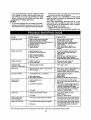
Trouble
Possible Cause(s)
Corrective Action
Engine fails to start
1.
2.
3.
4.
5.
6.
7.
1.
2.
3.
4.
5.
6.
7.
Engine runs erratic
1. Spark plug wire loose.
2. Blocked fuel line or stale fuel.
Blade control handle disengaged.
Spark plug wire disconnected.
Thmffie control lever not in starting position.
Fuel tank empty, or stale fuel,
Blocked fuel line.
Faulty spark plug.
Engine flooded.
3. Vent in gas cap plugged.
4. Water or dirt in fuel system.
5. Dirty air cleaner.
Engine overheats
Occasional skip
(hesitates) at high speed
1. Engine oil level low.
2. Airflow restricted.
Engage blade control handle.
Connect wire to spark plug.
Move throttle lever to startingposition.
Fill tank with clean, fresh gasoline.
Clean fuel line.
Clean, adjust gap or replace.
Crank engine with throttle in FAST
position.
1. Connect and tighten spark plug wire.
2. Clean fuel line;fill tank with clean,
fresh gasoline.
3. Clear vent.
4, Drain fuel tank. Refill with fresh fuel,
5. Clean air cleaner. See "Customer
Responsibilities" section of this manual.
1. Fill crankcase with proper oil.
2. Clean lawn mower engine.
Spark plug gap too close.
Adjust gap to .030".
Idles poorly
1. Spark plug fouled, faulty or gap too wide.
2. Dirty air cleaner.
1. Reset gap to .030" or replace spark plug.
2. Clean air cleaner.See "Customer
Responsibilities" section of this manual.
Excessive vibration
1. Cuffing blade loose or unbalanced.
1. Tighten blade and adapter.
Balance blade.
2. Replace blade.
3. Contact your SEARS Service Center.
2. Bent cuffing blade.
3. Bent engine crankshaft.
Mower will not
mulch grass
1. Engine speed too low.
2. Wet grass.
1. Move throttle lever to FAST position.
2. Do not mow when grass is wet; wait until
later to cut.
3. Mow once at a high cutting height, then
mow again at desired height or make a
narrower cuffing swath (1/2 width).
Do not cut off more than 1/3 of the total
length of the grass at any one cutting.
4. Sharpen or replace blade.
3, Excessively high grass.
4. Dull blade,
Uneven cut
1. Wheels not positioned correctly.
2. Dull blade.
Mower propels with
clutch disengaged
Mower will not propel
1. P]ace all four wheels in same
height position.
2. Sharpen or replace blade.
Drive clutch control adjustment needed.
Ad ust drive clutch control.See =Service
and Ad ustment"sect on of ths manual,
1. Drive clutch control adjustment needed.
1. Adjust drive clutch control.See =Service
and Adjustment"section of this manual.
2. Do not mow when grass is wet; wait
until later to cut.
2, Wet grass.
Note: For repairs beyond the minor adjustments listed above, contact your nearest SEARS Service Center.
16
Each lawn mower has its own model number. Each
engine has its own model number.
Your Sears merchandise has added value when you
consider that Sears has service units nationwide
staffed with Sears trained technicians...professional
technicians specifically trained on Sears products,
having the parts, tools and the equipment to ensure
that we meet our pledge to you..."we service what we
sell."
The model number for your lawn mower will be found
on a label attached to the lawn mower on the top rear
of the deck.
The model number for the engine will be found on the
blower housing of the engine.
All parts listed herein may be ordered through Sears,
Roebuck and Co. Service Centers and most Retail
Stores.
IFYOU NEED REPAIR SERVICE OR PARTS:
WHEN ORDERING REPAIR PARTS, ALWAYS GIVE
THE FOLLOWING INFORMATION:
REPAIR SERVICE
1-800-4-REPAIR
(1-800-473-7247)
*PRODUCT - "21" Mulching Rotary Mower"
*MODEL NUMBER - 247.376380
ORDERING PARTS
1-800-FON-PART
(1-800-366-727e)
*ENGINE MODEL NO. - 143.966000
*PART NUMBER
*PART DESCRIPTION
17
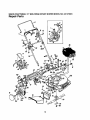
SEARS
CRAFTSMAN
21" MULCHING
ROTARY
MOWER
MODEL
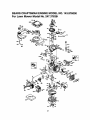
NO. 247.37638t.
Repair Parts
4
36
119
8
51
18
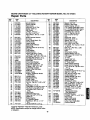
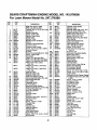
SEARS CRAFTSMAN
21" MULCHING
ROTARY MOWER MODEL NO. 247.37638|!
Repair Parts
KEY.
NO.
1
2
3
4
5
6
7
PART
NO.
720-0225
747-0824
710-1205
712-0279
750-0968
747-0855
736-0329
712-0287
736-0526
10
11
12
13
14
16
17
18
20
21
22
23
782-7007
731-0981A
710-1270
746-0883
749-0539B
731-1409
731-1501
714-0104
747-0710
782-7006
732-0731
682-7002
24
25
26
27
28
29
3O
31
32
33
34
35
36
736-0270
710-0167
17070
16855
782-7009
712-0324
714-0507
736-0278
736-0639
656-0612
747-0882A
749-0928
143.976000
37
38
40
42
43
682-7514
731-1137
746-0706
682-7513
71 0-1005
44
45
47
48
736-0270
71 0-0351
712-0296
713-0361
49
50
51
52
55
56
58
720-0241
731-0906
731-1483
726-0240
748-0377B
742-0741
736-0452
6O
710-1257
DESCRIPTION
Grip (2 Req'd.)
Control Handle
Rope Guide
Wing Nut 1/4-20 Thd.
Spacer .885" I.D.
Belt Guard
L-Wash. 1/4" I.D.*
; Hex Nut 1/4-20 Thd.*
Wave Wash..88" I.D. x 1.38"
O.D.
I Grass Catcher Bracket
Hub Cap
Oval C-Sunk Mach. Scr.
Throttle Body
Upper Handle
Side Chute Deflector
Mulch Plug
Internal Cotter Pin 5/16 Dia.
Hinge Pin
Plug Adapter
Torsion Spring
Mulch Plug Ass'y. Comp.
(Incl. Ref. 17, 20, 21, 22)
Ben-Wash..265" I.D. x .75" O.D.
Carriage Bolt 1/4-20 x .5" Lg.
Adjustable Cable Bracket
Paw! Plate
Chute Stop Bracket
Hex L-Nut 114-20 Thd.
Cotter Pin 3/32" Dia. x .75"
FI-Wash..328" I.D. x .68"
Spark Plug Insulator
Lower Pulley Half Ass'y.
Shift Rod
Lower Handle
Engine-Craftsman Model
143.976000
Housing Ass'y.
Flanged Bushing
6-Spd. Cable
Chain--Axle Ass'y.
Hex Hd. Tap Scr. 114-20x .38"
KEY,
NO.
61
62
63
64
65
66
67
66
59
70
71
73
74
75
77
79
748-0190
782-7563
736-0451
682-3006A
682-3007A
710-0260
710-0603
710-0654A
712-0267
720-0230
732-0725
736-0242
750-0736
750-0624
712-0291
710-0653
80
81
738-0137
748-0381
748-0188B
734-1826
741-0486B
712-0414
746-0710A
754-0343
711-0313
736-0524A
782-0027
731-0904
731-0905
710-0841
82
84
86
95
96
98
99
102
114
115
118
119
121
122
128
129
130
134
136
138
140
147
Lg.
Bell-Wash. 1/4" I.D.
148
Truss Mash. B-Tap Scr. #10 x .5' 149
152
Hex Patch L-Nut 3/8-24 Thd.
#48 Chain .500" Pitch x 38
Links
153
Hand Knob
154
Cable Mounting Cap
155
Rear Flap 4.8" x 17.5" Lg.
Cable Tie
163
165
Blade Adapter
177
21" Mulching Blade
Ben-Wash. ,39" I.D. x 1.14"
178
O.D.
t
Hex Bolt3/8-24 x 2.5" Lg.
I1
*Common Hardware--May Be Purchased Locally.
NOTE: Specificationssubject to change without notice
or obligation.
19
PART
NO.
731-0620
71 0-1174
711-0805
712-0711
746-0737
748-0318
741-0522
10622B
682-7506
710-0599
736-0864
741-0324
736-0160
710-0751
717-0417B
16500A
736-0300
713-0397
731-0924
732-0627
16864
770-0222M
DESCRIPll3ON
Spacer .513" I.D.
Bracket--Shift Plate
Saddle Washer .32" I.D.
R.H. Handle Wheel Brkt. Ass'y.
L.H. Handle Wheel Brkt. Ass'y.
Carriage Bolt5!16-18 x .62"
Hex B-Tap Scr. 5/16-18
Hex Tl'-Tap Scr. 3/8-16
Hex Nut 5/16-18 Thd.*
Grip
Height Ad. Lever
Be -Wash. 5/16" I.D.
Spacer .383" I.D.
Shld. Spacer .5" Dia.
Hex L-Nut 1/4-20 Thd.
Hex Wash. Hd. Tap Scr. 1/4-20
x .38" Lg.
Shk;l. Scr..342" Dia. x .268
PawI-,-R.H.
Pawl
Wheel Ass'y. Comp.
Sleeve Beadng 1/2" I.D.
Weld Top L-Nut 1/4-20 Thd.
S.P. Cable
"V"-Belf
Sleeve .526" I.D.
Blade Bell Support
21" Deck Ass'y.
Upper Control Housing
Lower Control Housing
Fl-"C"-Sunk Hd. Tap Scr. #10 x
.75" Lg.
Control Lever
Curved Hd. Bolt 5/16-18 x 2" Lg.
Shld. Pin 1.43" Lg.
Hex Jam Nut 3/3-24 Thd.*
Control Cable---51"
Ratchet Wheel 1.62" O.D.
Hex Flange Beadng
Spring--Nylon
Chain Cover Ass'y.
Hex "l-I'-Tap Scr. 1/4-20 x ,80"
Rear Shaft Ass'y. 21.44" Lg.
Hex Flange Brg..506" I.D,
FI-Wash, .531" I.D. x .930"
Hex Bolt 1/4-20 x .62" Lg.
(Grade 5)
Transmission Comp.
(See Breakdown)
I Hex Beadng Cup
i FI-Wash. ,386" I.D. x .87" O.D.
Gear Insert
6-Spd. Shift Lever
Shift Lever Spring
5-Spd. Rack Cable Brkt.
Owner's Manual
SEARS
CRAFTSMAN
21" MULCHING
ROTARY
MOWER
MODEL
NO. 247.376381
Repair Parts
34---_
33j
"----2
3O
°
_9
NO.
PART
NO.
5
6
7
8
710-1062
736-0329
717-0418A
713-0400
7360336
741-0413
16500A
736-0314
9
741-0479
1
2
3
4
11
12
13
15
16
17
18
19
20
21
717-1216
748-0208A
721-0212
756-0330A
736-0270
712-0351
738-0440
736-0344
738-0826
656-0008
22
23
24
25
26
27
28
29
30
31
741-0556
736-0270
782-7570
712-0138
732-0357
717-0419A
741-0415
717-0616
741-0414
721-0213
tPart
of Transmission
DESCRIPTION
46
45
KEY.
NO.
Hex Patch Bolt 1/4-20 x 1.25"t
L-Wash. 1/4" I,D.*
Upper Hsg. Halft
#48 Sprocket 7 T x 1/2 Pitcht
FI-Wash, 5/8" I.D. x .030_
Hex Flange Brg. ,631" I.D.t
Hex Bearing Cupt
Thrust Wash, .382" I,D. x
.70" O.D.t
Thrust Bearing .375" I,D. x
.812" O.D.t
11 Tooth Pinion Shaft_
Flange Bearingt
Oil Sealt
Fl-Pulley 5.06" O.D.
Bell-Wash..265" I.D. x .75"
Hex L-Nut 1/4-28 L.H. Thd,
Shld. Spacer .375" Dia. x .170
FI-Wash..390" I.D. x 1.0"
Shtd. Bolt .375" Dia. x .40"
Fl-ldler Plastic 1.50" Dia.
(Incl. Ref. #22)
Needle Brg..375" x .31
Bell-Wash..265 =I.D.
Idler Brk't. Ass'y.
Hex Patch L-Nut 1/4-28 Thd.
Extension Spring 1.12" Lg.
Lower Hsg. Half-iFlange Bearing .566 Dia.t
Shaft Ass'y.t
Flange Beadng .629 Dia.t
Oil Seal .625 Dia,t
Complete,
32
33
34
35
36
37
38
39
40
42
43
44
45
46
47
48
49
50
51
54
56
57
58
59
60
63
64
65
66
67
70
Ref. No. 36.
2O
PART
NO.
782-7569
736-0722
710-0436
736-0410
717-O417B
738-0102
734-1826
736-0105
710-1241
741-0492A
17733
782-0516
710-0653
720-0190
732-0639
731-1281A
710-0352
782-7558
710-0599
782-7554
710-1242
736-0242
731-0981A
746-0710A
736-0222
712-0147
710-1003
710-0167
710-0603
712-3027
736-0329
DESCRIPTION
Belt Keeper
L-Wash. #10 I.D.t
Hex B-Tap Scr. #10 x ,62"t
Hex Washer .26" x .88"
Transmission Comp,
Front Axle Bolt
Wheel Ass'y. Comp. 8 x 2"
Bell-Wash..380" I.D. x .88
Hex Wash. Hd. Scr, 1/4 x 1" Lg.
BlockBushing
Axle Ass'y.
Height Adj. Bracket
Hex I-F-Tap Scr. 1/4-20 x .38"
Knob
Spring Lever
Plastic Front End
Hex B-Tap Scr. 1/4" x .38"
Belt Cover
Hex Wash. Hal.TT-Scr. 1/4-20
TransmissionBelt Cover
Torx Truss Hd. Scr. 5/16 x .75"
Bell-Wash..345" I.D. x .88"
Hub Cap
S.P. Cable
External L-Wash. 1/4" I.D.
i Speed Nut #10-24 Thd..
! HexTapScr #10-16x 5 Lg.
i Carr. Bolt 1/4-20 x .5" Lg.
Hex B-Tap Scr. 5/16-18 x .5"
Hex Flange L-Nut 1/4-20 Thd.
L-Wash. 1/4" I.D.*
SEARS CRAFTSMAN ENGINE MODEL NO. 143.976000
For Lawn Mower Model No. 247.37638t
75
21
SEARS CRAFTSMAN ENGINE MODEL NO. 143.976000
For Lawn Mower Model No. 247.376380
KEY.
NO.
1
2
6
9
10
11
12
12C
14
15
16
17
18
19
20
25
26
30
40
41
PART
NO.
36177
27652
36059
590568
36002
36003
32447
36005A
28277
36006
36008
31335
651018
36082
36010
36011
650802
36178
36073
36074
36075
36070
36071
36072
42
43
45
46
48
50
52
69
70
72
73
75
80
81
82
83
85
86
89
90
91
92
93
100
101
103
110
36076
36077
36078
20381
36023A
32610A
36030
36031A
29914
36032A
36151
30572
28833
36010
30574A
30590A
30591
36057
36034
650924
611154
611155
611156
650815
650816
34443A
610118
651007
36054
KEY.
NO.
DESCRIPTION
RPM High 3100 to 3400
RPM Low 2000 to 2300
Cylinder (Incl. 2, 10, 12, 20 & 125
Dowel Pin
Breather Element
Screw, 10-24 x 3/4"
Breather Valve Body
Check Valve
Breather Tube
Breather Cover & Gasket
Washer
Governor Rod (Machined)
Governor Lever
Governor Lever Clamp
Screw, Torx "I-15, 8-32 x 19/64"
Governor Spring
Oil Seal
Blower Housing Baffle (Incl. 1951
Screw, 1/4-20 x 5/8"
Crankshaft
Piston, Pin, Ring Set (Std.)'
Piston, Pin, Ring Set (.010 O.S.)
Piston, Pin, Ring Set (.020 O.S.)
Piston & Pin Ass'y. (Std.)
(Incl. 43)
Piston & Pin Ass'y. (.010 O.S.)
(Incl. 43)
Piston & Pin Ass'y. (.020 O.S.)
(Incl. 43)
Ring Set (Btd.)
Ring Set (.010 O.S.)
Ring Set (.020 O.S.)
Piston Pin Retaining Ring
Connecting Rod Ass'y. (Incl. 46)
Connecting Rod Bolt
Valve Lifter
Camshaft (MCR)
Oil Pump Ass'y.
Mounting Flange Gasket
Mounting Flange (Incl. 72 thru 85
Oil Drain Plug (Incl. 73)
Drain Plug Gasket
Oil Seal
Governor Shaft
Washer
Governor Gear Ass'y. (Incl. 81)
Governor Spool
Idler Gear
Screw, 1/4-20 x 1-9/16"
Flywheel Key
Flywheel
Flywheel Fan
Belleville Washer
Flywheel Nut
Solid State Ignition
Spark Plug Cover
Screw, Torx T-15, 10-24 x 15/16"
Ground Wire
22
119
120
125
PART
NO.
130
135
150
151
151A
169
172
174
177
36061
36120A
36471
36472
29314B
29315C
6021A
35395
31672
31673
40016
27234A
32755
30200
650925A
186
187B
190
191A
192
193
194
195
198
199
202
203
204
205
215
239
240
36009
36035
36013
36012
36016
36015
36014
610973
36017
36018
36482
31342
651O29
651030
36051
36048
36044A
243
245
250
251
255
256
260
261
262
263A
275
276
277
285
287
290
292
299
300
301
305
307
308
310
650899
36046
36154
650928
36110
650983
36153
650737
650929
36156
36107
36043
650927
34449A
650926
34357
26460
650900
36066
35355
36063
35499
36040
36147
126
DESCRIPTION
Cylinder Head Gasket
Cylinder Head
Exhaust Valve (Std.) (Incl. 151)
Exhaust Valve (1/32" O.S.)
Intake Valve (Std.) (Incl. 151)
Intake Valve (1/32" O.S.)
Screw, 5/16-18 x 1-1/2"
Resistor Spark Plug (RJ19LM)
Valve Spring
Lower Valve Spring Cap
Intake Valve Seal
Valve Spring Box Gasket
Valve Spring Box Cover
Screw, 10-24 x 9/16"
Carburetor MountingStud,
Torx E-5
Governor Link
Carburetor Gasket/Air Baffle
Brake Lever Ass'y.
Brake Control Lever
Brake Control Lever Link
Brake Spring
Retaining Ring
Terminal Ass'y.
Brake Control Lever Spring
Brake Lever Bushing
Compression Spring
Compression Spring
Screw, Torx T-10, 5-40 x 7/16"
Screw, Torx T-10, 6-32 x 17/32"
Control Knob
Carburetor to Air Cleaner Gasket
Air Cleaner Body (Incl. 239, 299
& 35O)
Screw, 10-32 x 2-3/32"
Air Cleaner Filter
Air Cleaner Cover
Lock Nut 1/4-20
Control Plate
Screw, 8-32 x 21/64"
Blower Housing
Screw, 1/4-20 x 1/2"
Screw, 1/4-20 x 11/16"
Starter Grill
Muffler
Locking Plate
Screw, 5/6-18 x 2-11/32"
Starter Cup
Screw, 8-32 x 21/64"
Fuel Line
Fuel Line Clamp
"U" Type Nut Clip
; Fuel Tank (Incl. 301)
; Fuel Cap
Oil FillTube
"O" Ring
Fill Tube Clip
Dipstick
SEARS CRAFTSMAN ENGINE MODEL NO. 143.976000
For Lawn Mower Model No. 247.376380
KEY.
NO.
346A
347
350
370A
370B
380
390
PART
NO.
DESCRIPTION
KEY,
NO.
PART
NO.
400
416
36062B
36085
417
900
900
650760
---
28763
650898A
36045
36261
36155
632671
590702
Screw, 10-32 x 35/64"
Screw, 10-32 x 27/64"
Primer
LubricationDecal
Control Decal
Carburetor(Incl. 187B & 239)
Rew nd Starter
(Note: This engine could have been built with
590739 starter. Refer to the design ofthe rope pulley
strength ribs for part identification.Individualstarter
parts do not interchange.)
DESCRIPTION
i Gasket Set
Spark ArrestorKit (Incl. 417)
(Optional)
Screw, 8-32 x 3/8" (Optional)
Replacement Engine--NONE
Replacement S/B 750791A,
Order 71-999
CARBURETOR NO, 632671
1A70-1538
I
KEY.
NO.
1
5
6
7
25
25A
27
28
29
30
632671
632539
632593
632541
650506
632675
632701
632544
632543
632648
632551
3t
32
33
36
37
37A
38
38A
39
40
47
632637
632672
632673
632674
632547
632547
632545
632545
632549
632676
632554
m
I
21
|
4'
I
I
PART
NO.
23
DESCRIPTION
Carburetor
Throttle Shaft & Lever Ass'y.
Dust Seal
Throttle Shutter
Throttle Shutter Screw
Float Bowl
Idle Restrictor
Float Shaft
Float
Float Bowl to BodyGasket
Inlet Needle, Seat & Seat
Retainer (Incl. 31)
Seat Retainer
Bowl Drain Screw
Bowl Drain Washer
Main Nozzle Tube
"O" Ring, Main Nozzle Tube
"O" Ring
Spring, Main Nozzle Tube
Spring
Float Bowl Retainer
Main Fuel Jet
Welch Plug, Idle MixingWell
SEARS CRAFTSMAN ENGINE MODEL NO. 143.976000
For Lawn Mower Model No. 247.376380
STARTER 590702
--11
13
KEY.
NO.
PART
NO.
-1
2
3
4
5
6
7
8
11
590702
590599A
590600
590696
590601
590697
590698
590699
590700
590703
12
13
590535
590701
DESCRIPTION
i Recoil Starter
Spring Pin (Incl. 4)
Washer
Retainer
Washer
Brake Spring
Starter Dog
Dog Spring
Pulley& Rewind SpringAss'y.
Starter Housing Ass'y.
(40 Degree Grommet)
Starter Rope (98" x 9/64" Dia.)
Starter Handle
m5
STARTER 590739
KEY.
NO.
PART
NO.
-3
6
7
8
11
590739
590740
590616
590617
590618A
590638
12
590535
13
14
590701
590741
24
DESCRIPTION
Rewind Starter
Retainer
Starter Dog
Dog Spring
Pulley& Rewind SpringAss'y.
Starter Housing Ass'y.
(40 Degree Grommet)
Starter Rope (Length 98" x
9/64" Dia.)
Starter Handle
LockingTab
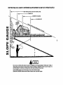
USE THIS PAGE AS A GUIDE TO DETERMINE SLOPES WHERE YOU MAY NOT OPERATE SAFELY.
I
| _
|
I
..................
SIGHTAND HOLDTHIS LEVELWITH A VERTICALTREE
| -_
I
.............
A POWERPOLE
............
A CORNEROFA BUILDING
u_
¢,1
C:)
15°
WARNIN 4"_
Do not mow on inclines with a slope In excess of 15 degrees (a rise of approximately 2-1/2 feet every 10 feet). A
riding mower could overturn and cause serious injury, If operating a walk-behind mower on such a slope, it Is
extremely difficult to maintain your footing and you could slip, resulting In serious injury.
Operate RIDING mowers up and down slopes, never across the face of slopes.
Operate WALK-BEHIND mowers across the face of slopes, never up and down slopes.
Forthe repairor replacementpartsyouneed
delivereddirectlyto yourhome
Call7 am - 7 pro,7 daysa week
1-800-366-PART
(1-800-366-7278)
Forin-homemajorbrandrepairservice
Call24 hours a day,7 daysa week
1-800-4-REPAIR
_I_R SER_C_
(1-800-473-7247)
Forthe locationof a
SearsPartsandRepairCenterinyourarea
Call24 hours a day,7 daysa week
1-800-488-1222
Forinformationonpurchasinga Sears
MaintenanceAgreementor to inquire
aboutan existingAgreement
call 9 am - 5 pm, Monday-Saturday
1-800-827-6655
SEARS
America's Repair Speciatists
SEARS
mmmmmm
mmmmm
Owner's Manual
CRAFTSMAN°
6.0 CABALLOS
DE FUERZA
21" IMPULSADO A POTENCIA
6 VELOClDADES
CORTACI=SPED CON MOTOR ROTATIVO
Modelo No.
247.376381
Precauci6n:
Lea y observe
todas las reglas
y instrucciones
de seguridad antes
de operar este
equipo
Sears, Roebuck
Printed in U.S.A.
And Co., Hoffman
Estates,
IL 60179
USA
770-0222M
I&
ADVERTENCIA."
•• El
Californiacausan
c_ncer,
defectos
de contiene
nacimiento
u otros problemasde
Escape del Motor
de este
products
qufrnicosque
de acuerdoreproduccibn.
al Estado de
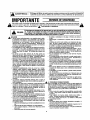
IMPORTANTE
_ib
grosparaeloperadory paraotros. Esnecesarioleeryseguir todastaa instrucciones
quese encuentranen estemanuatantesdeintentar
ste sfmboloindicainstrucciones
importantesparasu seguridad.Estasinstrucciones
se debenseguir rigurosarnanteparaevitarpeli-_b
operar sucortac_sped.Cuandoyeaestesimbolo--- _
Presteatenei6na sa adverlancla.
&
,_
.o. As
DE
S GU.IOAO
Su¢ortaa_ped lue disefladoparaser operadosegdnlas reglasdesegoridadquese encuentranen este manual, AI igual quecon¢ualquierotto equipo,erroro falta decuidadoperpartsdel opersdorpuedereaultaren
PELIGRO: ser
as lesiones.
Estecortacispedas
capazde amputarmanesy
y puedearroar objetosfuertemente.
Lafalta
deatenciGn
a estasreglas puedeaausar
series lesloneso pies
la muerte.
OPERACION
Lea este manualcuidadosamente
y per completeantesde tratar
de ensamblaresta m_quina. Lea, comprenday siga todaslas
instrucciones
dela mz_quinay del manualantesde la operaci6n.
Familiar_cese
con los controlesy el use adecuadode esta
m_quina antesde ponedaan funcionamiento. Maatengaeste
manualenun lugarseguroparapoderconsultarloconfrecuencia
y parahacerlospedidosderepuestos.
• Su cortac_sped
con motorrotativoesuna m_qulnadeprecisi6n,
no unjuguete. Per In rants,es necesafiomanejarloconmucha
precauci6n.Lasunidadfue disefiadaparacumplirconunasofa
funci6n: para cortarel c6sped. No la utilicepara ningunaotra
funcibn.
• No permitaque los nifiosmenoresde 14 aries operen una
m_quinadeestetips. Nifios mayoresde14 anosdebenoperarla
unidad bajola supervfsi(Sn
de un adults. Solamente personas
quaconocenbianel manejode la m_quinadebenutilizarla.
• Mantengael_ireadetrabajolibradeobjetos,personasy animales
dorn_sticos.Si se acercaunapersonao animal,pareel motor
paraevitaraccidentescauseriesper la cuchillau objetosarrojados. A pesarde que el _rea de operaei6ndebe estar limpiade
objotos, existsla poaibilidadde que cualquiarcosapasadaper
altosea arrojaday causelesionesal operador u otraspersonas
en la corcania,
• Inspeccionecuidadosamente
el ;treaen el cual va a trabajar,
quitando rsrnitas, alambres,huesos,jugueteso otros objetos
qua puedanserarrojadosper la m_quinay causelesionesserias
al operadoro a otras personas. Planseel mode en que desea
cortarel c6spedparaevitar que la m_iquinaarrojeel zacatea la
carretera,acerao trsnsebntes.Parsevitar]esiones,mantengaa
losnifios,animalesdom_sticos
y otraspersonasa unadistancia
do 75 piesdelcortaa6sped
mientrasquese encuentreen funcienarniento.
• Use siemprsanteojos pmtectoresmientrasopera o reparela
m_quinaparaprotegerlossinscontrala matedaquapuedaarroarel cortac6sped.
_lJ
• Usezapatosdesuelagruesey pantalones
y camisaajustadosqua
cubranper completeel cuerpo. Es recomendableuserbetas o
zapatosconpunteradeacorn. No useropa sueltani alhajasde
ningen tips, ya quase puedenatoraren la m_quina. Noopera la
unidaddescalzo,consandaliasni contenis.
• Mantengalas manes y los piesalejadosdo las piezasen movimiento. Mant6ngase
siemprealejadodel orificiodedescargaya
quala cuchillagiratodapuedacausardafio.
• Muchaslesiones sueedendebidoa que el eortac_spedse pasa
sebre el pie duranteuna ca[da. No se sostengade] cortac_sped
sise va a caer;sueltela palancainmediatamente.
• Nunca jaleel cortac_sped
haciaustedmientras estecaminando.
Si tienequa ialarla m_quina hacia atr_s debidoa unapared u
obstrucci6n,primersmire haciaabajoy haciaatr_sy luego siga
lossiguientes pasos:
Al_jesedel eortac6sped
para extendereompletamentelos brazes.
• ASeOL_rese
deestarbienequilibrado
yen buenaposici6n.
• Ja]e la m_quina despacio,a rnanos de la rnitad hacia donde
est_ usted.
• Repitaestos pasostal come sea necesario.
2
No utiliceel cortac_sped
siesta bajoLainfluenciade alcohoio
drogas.
• Desembrsgueel mecanismo de impulse antes de arrancarel
motor.
•
•
•
•
•
•
•
•
•
La pa[ancade control de la cuchillaes on mecanismode seguridad. No deje de usarlacuandoutilice la m_quina,de Io contrario puedensuceder]esionessedasper medio delcontactscon
la cuchiila. La palanca se mueve libremente en arnbas direcclonesy se desacoplaautom_ticamenteel eoltada.
Nunoaopera la m_quinacuandoel c6spedeste mojado. Unresbal6no una caidapuedetener seriasconsecuencias.Agarreel
mungo con firmeza y carnine, no corra. Use la m_iquinas61o
cuandohayabuenaluznatural o artificial,
Pareel movimiento de la cuchinaal cruzarcarninos de grava,
aceraso carreteras.
S[ ]a unidadempiezaa vibrarfuerade Io normal,pareel motory
reviseinmediatamenta
a ver cual es la caasa. Generalmente,
la
vibraci6nindicaquehayalgOnproblema.
Pareel motory espershastaqua la cuchillacesesumovimiento
antesde quitar el recogedordec_spedo delimpiarel recogedor.
La cuchillasigua girandoper unosse0undosdespu6sde apagar
el motor. No seacerquoa la cuchillaantesdequa pareper complete.
Nunca use la m_.quinasin tenor los resguardosapropiados,el
recogedor dec_sped,placesu otrosmecanismosde protecci(tn
en su lugar.
El silenciadory el motor sacalientany puedencausarquemaduras. No los toque.
Usesolamente aceesofiosaprobadosper el fabdcante paraesta
m_quina, Lea, comprenday siga todas las instruccionessuministradascon el accesorioaprobado.
Si ocurrensituaciones quano se mencionan en este manual,
tonga cuidadoy use buen juicio. Llamo a su distdbuidor para
recibir asistencia.
II. QPERACI(_N
EN TERRENOPENDIENTE
Parasu seguddad,use el clis[metroincluidoconeste manualpara
rsedir[aspendientes
antesde pnnerenoperaci6nesta unidadenun
terrenopendienteo montanoso, Si elterreno pendientees mayora
los 15 grades, tal comese demuestraen el cliaimetro,no use esta
unidaden esa_reaya qua puederesultarenserieslesiones.
HAGA:
• Cortea trav_s de lasuperficiede las pendientes;nuncade arriba
a abao. Tengatouche cuidadoal cambiarde dirscciSnen las
pendantes.
• Tonga cuidadocon huecos, grietas, objetos poco visibles o
baches El zacatedemasiadoaltopuedeesconderob etos.
•Este seguro deride pone los pies. Un resbalbn o ca[dapuede
causerseriaslesiones.
NO HAGA:
• No corteel c_spedcercaa declives,alcantarillaso terrapl_n.El
operador puedeperder el equilibrio,
• No torte el c_spedenterrenosconpendisntesmayoresa los 15
gradestal come se demuestraenel clisimetro.
• Nocorteel s_spedcuandoeste mojado. Si lospies no est_nbien
seguros eloperadorse puederesbalan
_1
lit. NII_OS
Acddentastr_gicospuedensucedarsi el opersdornoestaalertoa la
presenciade nirospaquaSos.Losnifiosa menudosoncunososde
la rnaquina y su funci6n. Nunca supongaqua los nifios permanacar_nanel misrnositiodondaUd. losrio hacepoco.
• Mantengaa los nifioslejosdel area de trabajoy bao la supervisi6nde un adultoadem_sdeloperadordela maquina.
• Estealartay atoaguela unidadsi algOnnifiose acercaat area.
• Antesy al movereshaciaatria, asagQresaque no hzyannifios
pequefios.
• Nunca permitaqua nifiosmenores de 14 ariasutilicanel curtacasped.
• Tangamucho cuidadoal doblaresquinas, arbustos,_rboles u
otrosobjetosqueobturanlaviaibilidadde anniro o unpaligro.
IV. MANTENIMIENTO
_i
•
•
•
•
•
•
Sonextremadamanta
irrflarnables
y losgases
sonexplosivos.
Tangarnucho
cuidado
al manejargasolina
y otroscombustibles.
Utilicesolamenteuncontenedoraprobado.
Nuncaquite eltap6ndeltanquadegasolicani a_adacombustible
mientras que el motoreste enfuncionamiento.Permita qua et
motor enfdepor Io menospor dos minutosantesde Ilanarel
tanqua.
Vuelvaa colocarel tepdn deltanquey lirnpiecualquierchorrso
antesde encenderel motorya quapuedacausarun incandioo
unaexplosion.
Apaguetodos Ins cigarflles, puma, pipasu otros medios de
ignicidn.
Nuncanenael tanquebajotechoya qua]as gasesinflarnables
se
acumularanenat _res.
Nunca almacena la m_quina o et contenedorde combustible
donde hayanllamas o chispastalescomoel tanquede agua,
calantadores
u homo.
Nuncaeneiendael motorbajotecho.
• Parsdisminuirel peligrode incandio,mantengael cortacdsped
limpio sin zacate,hojas u otros residuos. Lirnpiacualquier
chorreodeacaiteo oasolina. Permita quael cor_acasped
enfrfe
por Io menos 5 rninutosantesdealrnacanarlo.
• Antesde limpiar,repararo inspeccionar
la m_quina,asegOrees
de que la cucrilla y todes ]as plazasen movirniento paren.
Dasconacteel cablede bujfade encendidoy mantangael cable
lejosfiela bujfaparaavitarun arranquarepentino.
• Revisela cuchillay los parnosfie montajeconfrecuanciapara
asegurarque estanapretados.Tambian revisevisualmenteque
la cuchillano este darada(ex:doblada,agriatada). Reemplaca
con unacuchillaquecumpiacon las espacificaciones
originales
de la m_quina.
• Mantengatodaslas tuercas, parnosy tornillosapretadospara
asegursrqua el aquipoeste en buenacondicidnde funcionamiento.
• Nunca trste de carnbiar los mecanisrnesde segufdad. Revise
queestanfuncionandoadecuadamente,
• Si golpeaalgan obeto, pare el motor quiteel cablede bujiay
revisebienparaver si haydafioa. Rapareel dafioantes deusar
el cortacasped.
• Nunca tratede ajustar las ilsntasni la altura de corterniantrss
queel motoresteencendido.
• Los componentes
del colectorde zacatase puedendesgastar,
dafiar o deteriorsr,Io qua puedecauesr qua plazasen movirnientoest_nexpuestasy arrojen objatos. Parasu seguridad,
revise con frecuencialos componentesy reernplacecon los
repuestosrecomandados
por el fabricante,eonformesea nececarlo.
• Las cuehiltasdel cortacaspedson filosas y pueden co,lar.
Envuelvalascuchi]laso utiliceguantesy tengarnuchocuidadoal
daflesmantenimianto.
• No cambiela progrsrnacidn
del reguladordal motor o Ilevaa
axtremaveloeidadel motor. Las velocidadas
excesivassonpeliorosas.
MANUALDEL
PROPIETARIO
,_ADVERTENCIA
-- suRESPONSABlUDAD
Restrina el usode esta m_quina rnotorizadaalas personasque
esn, entendany observanlas advartenclaae instrucciones
contenidasenestemanualyen Is m_quina.
FELICITACIONES
por su compra de una Cortacesped
Craftsman Sears. Ha sido disefiada, concebida y fabrioada
pare pmpomionade la confiabilidad y el funcionamiento
mejor posibla.
ESPECIFICACIONES
DEL PRODUCTO
Caballos de fuerza:
6.0
Capacidad de aceite del motor:
ClasificacibnAPI: SF, SG o SH
Por favor consulte con su Centro/Departamento de Servicio
Sears rods cercano si experimenta algLinproblema que no
puede solueionar fdcilmente. Tenemos t_cnicos competentes y bien entrenados, y las herramientas apropiadas
para servir o reparar esta unldad.
Capacidad de
combustible
Pot favor lea y guarde esta manual. Las instruccionesle permitirdn armar y mantanar apropiadamante su cortac6sped.
Observe siempre las "REGLAS DE SEGURIDAD",
1-1/2 cuartosde gal6n
aproximadamente
(Sin plorno)
Buj_a (Separacidn .030 pulg.) ChampionJ-19LM
(o equivalente)
Momento de torsibndel
perno de la cuchilla
NUMEROS DE
MODELO
247.376380
NUMERO DE
SERIE
ACUERDO
FECHA DE
COMPRA
SE ENCONTRARAN EL MODELO Y EL NUMERO DE
SERIE EN EL ROTULO PEGADO AL CUERPO DE
LA CORTAC_SPED
450/600
pulgadas/libras
DE MANTENIMIENTO
Estd disponible pare este producto un Acuerdo de Mantenirnientode Sears. Pot defalles consulte a su tienda Sears
mds cercana.
ADVERTENCIA: Esta unidad astd equipada con un motor
de combusti6n lnterna y no deberfa usarsa en o cerca de
tierras no mejoradas cubierfas de bosques, matorrales o
hierbas a menos que el sistema de escape del motor estd
equipado con un supresor de chispas que cumpla con las
leyes locales o estafales aplicables (de existir).Si se usa un
supresorde chispas, el operador deberfa mantenerlo en una
condici6n de trabajo efectiva
USTED
DEBERIA
REGISTRAR
AMBOS: EL
NUMERO DE SERIE Y LA FECHA DE COMPRA Y
GUARDARLO EN UN LUGAR SEGURO PARA REFERENCIA FUTURA.
RESPONSABILIDADES
PROPIETARIO
SAE 30
(27 onzas)
DEL
Ea el eetado de California Io anterior es requeddo por ley
(Secci6n 4442 del C{_digode Recursos Peblicos de California). Otros estados pueden tener leyes similares. Las leyes
federales se aplican en tierras federales. Esfa disponible el
supresorde chispas para el silenciadora tray,s de su Cantro/Departamento de Servicio autodzado de Sears mds cercano (Vea la secci6n de PIEZAS DE REPUESTO de aste
manual).
•
•
Leer y observar las reglas de seguridad.
Observar un programa regular para mantener, cuidar, y
usar su cortacdsped.
•Observar
las instrucciones bajo "Responsabilidades del
Propiatario" y "AImacenamiento" de este Manual dal
Operador.
GARANTIACOMPLETADE DOSAJ_OSPARALA CORTACI_SPED
A GASOLINACRAFTSMAN
Por dos afios desde la fecha de compra cuando esta Cortacdsped Craftsman sea mantenida, lubricada y
puesta a punto de acuerdo con las instruccionesde operaciSny mantenimiento en el manual del operario,
Sears reparard libra do costo cualquier defecto de material o de mano de obra.
Esta garantfa excluye las cuchillas,adaptadores de las cuchillas,las correas, filtros de eke y bujfas, que son
partes descartables y se gastan durante el use normal.
Esta garanfia se aplica por 30 dias solarnente desde la fecha de compra, siesta cortac_sped se usa para
fines comerciales o de alquiler.
ESTA DISPONIBLE
EL SERVICIO DE GARANTIA
CONSULTANDO
CON EL CENTRO DE SERVICIO
SEARS MAS CERCANO
EN LOS ESTADOS UNIDOS. ESTA GARANTIA
SE APLICA SOLAMENTE
MIENTRAS ESTE PRODUCTO ESTE EN USO EN LOS ESTADOS UNIDOS.
Esta garant{a le otorga derechos legales especificos y usted puede tarnbientoner otros derechos que varian
de Estado a Estado.
SEARS,
ROEBUCK AND CO. DEPT. 817WA, HOFFMAN
4
STATES, IL 60179
REGLAS DE SEGURIDAD . .. ...............
2, 3
ESPECIFICACIONES DEL PRODUCTO .........
4
ACUERDO DE MANTENIMIENTO ..............
4
RESPONSABILIDADES
DEL PROPIETARIO ...................
4, 10-12
GARANTIA ................................
4
ACCESORIOS ..............................
5
ENSAMBLAJE ............................
6, 7
OPERACION .............................
MANTENIMIENTO .......................
AJUSTES ..............................
ALMACENAMIENTO ......................
PIEZAS DE REPUESTO .....................
RESOLUClON DE PROBLEMAS ..............
MEDIDOR DE PENDIENTES .................
7-10
10-12
13-15
15-16
16
17
18
Estos accesorios estaban disponibles cuando la cortac6sped se compr#. Est_lntambi_n disponibles en la mayorfa
de las tiendas minoristas, per cat,logo y en los centros de servicio de Sears. La mayorfa de las tiendas Sears
pueden ordenar esos artfculos para usted si informa el n_mero de modelo de su cortacesped.
MOTOR
Plug
de alre
clador
CORTAC_SPED
"
or
5
Poste de
IMPORTANTE: Esta unidad es enviada SIN GASOLINA o ACEITE en el motor. Asegdrese de administrar el acelte y gasoline el motor antes de
ponerla en funcionamlento.
NOTA: Se puede ver el lado derecho o izqulerdo
del cortacdsped desde la posici6n de operaci6n.
PARASACARLA M._0UINA DE LA CAJA
• Quite las grapes, rompa el hule de las tapas de
arriba o corte la cinta adhesiva en la parte inferior
de la caja y quftela para abrir el cart6n.
• Saque las piezas sueltas incluidescon esta unided
(manual del propietario,canaleta lateralde descarga,
botellade aceite y soportedel colectorde crisped).
• Corte a Io largo de los puntos y deje que el cart6n
caiga.
• Quite el material de empaque.
• Saque o deslice del cart6n la unidad. Revise el
cart6n para que no queden piezas sueltas.
NOTA: Mantenga el soporte del colector de crisped
en un lugar seguro. Si usted compra el colector de
c@spedopcional, monte el soporte en el lado derecho
de la palanca superior tel como se demuestra en la
pagina 18 de este manual, Ilave 10.
Cable de la
BuJfa
FIGURA 1.
la Cuchllla
Superior
Gufa do la
Cuerda
Arranque
Cable
de la
Bujfa y
Soporte
del
Mango
C0M0 MONTARSU C0RTACI!SPED
• Desconecte el cable de bujfa de la bujfa. Conecte
a tierra el cable unidndolo al poste de retencibn
listoa funcionaren su cortac_sped. Vea las figures
1 y 2. (El cable de bujfa se demuestra en la figure
1 sin la bota de hule para mas claddad.)
• Quite las piezas de cart6n que se encuentran entre
el mango superior e inferior.
• Jale hacia adelante y hacia atrds el mango superior
para levantarloen la posici6nadecuada.
• Aseg_rese de que el mango inferioreste colocedo
bien'en los soportes. Apriete los botones que se
encuentran en cada lado del mango (los pernos
deben de calzar bienen el mango).
NOTA: La mdquina se entrega con el mango ajustado en la posici6n mas aria. Si desea ajustarlo de
otra manera, yea la SECCI6N DE AJUSTES.
• Con un par de alicates, quite las prensas del
agujero exterior en los pernos soldados que se
encuentran en los soportes del mango. Coloque
las prensas en el agujero interior.
• La gufa para la cuerda esta pegada al lado derecho
del mango superior. Afloje la tuerca mariposa que
asegura la gufa para la cuerda.
• Con el cable de bujfa desconectado y puesto a
tierra, sostenga la palanca de control de la cuchille
contra la palanca superior y jale la cuerda de
arranque lejosdel motor. Suelte la palenca de control de la cuchilla. Deslice la cuerda de arranque
en la gufa. Apriete la tuerca mariposa.
Enchu_ de
Code
FIGURA 2.
\
Soporte del
Mango
Mango
Agujero
Interno
Prensa
Pasador
Soldado
FIGURA 3.
\\
Cuerda
Cuerda de _,,A
Arranque _,\
FIGURA 4.
6
Tuercaa
• Aseg_rase
dequetodoslospernosy tuercas
est_n
apretados.
Tambi6n,
asegL_rese
de volver a conec-
Tapadero del Triturador
Continuo
tar el cable de bujia antes de encender el cortac_sped.
• Su cortac0sped ha sido enviado como un cortador. Para descargar el c_sped al lado, precede de
la siguiente manera:
• Para convertirsu cortac_sped de un trituradorcontinuo a un cortac_sped con descarga lateral,
levante el tapadero del tdturador. Vea la figura 5.
Des]ice los dos ganchos en el deflector de descarga lateral debajo del pasador de bisagra an el
conjunto del triturador de desperdiclos de c6sped.
Baje el tapadero del triturador de desperdicios de
FIGURA 5.
CONOZCA SU CORTACI=SPED
LEA ESTE MANUAL Y LAS NORMAS DE SEGURIDAD ANTES DE PONER SU M,_QUINA EN FUNCIONAMIENTO. Compare las ilustracionescon su cortacdsped para familiarizarse con ]a Iocalizacibnde varioscontroles
y ajustes. Guarde este manual para futuro uso.
Palanca de Control de Velocldad
del
Je Control de
la Cuchllla
Embrague
de Mando
Sumldero y Varilla
de Comprabaci6n
de Aceite
Cuerda
Cuerda,
Arranque
Ajustador
de la Rueda
LADO IZQUIERDO DEL CORTACESPED
Rueda Frontal
Tapadero del
Triturador Contlnuo
FIGURA 6.
le la
Bujfa y Bota
CUMPLECON LOSREQUISITOSDE SEGURIDADDE CUCHILLASCPSC
Los Cortac_sped Sears "Camina-Detras" cumplen con los requisitos de seguridad del American National Standards Institute y la U.S. Consumer Product Safety Commision. La cuchilla gira cuando el motor estd encendido.
PALANCA DE CONTROL DE LA CUCHILLA--debe de
mantenerseabajo hacia el mango para poderencendery
funcionar el motor. Su_ltelapara pararel motor.
CUERDA DE ARRANQUE--usada para encender el
motor.
CEBADOR--bombea combustible adicional del carburador al cilindro para usarse cuando se trata de
arrancar un motorfrfo.
PALANCA DE CONTROL DE VELOCIDAD DEL
MOTOR---permite la selecci6n de velocidad (rdpidodespacio)
CONTROL DEL EMBRAGUE DE MANDO---debe de
sostenerse contra el mango para conectar la transmisi6n. Suelte el controlpara parar [as ruedas.
PALANCA DE CAMBIOS (VELOClDAD)_se usa
para selecolonar una de las seis velocidades.
7
ANTES DE USAR SU CORTAClSSPED, DE NUEVO HAGA REFERENCIA
DE LA PAGINA 2 DE ESTE MANUAL. SIEMPRE TENGA CUlDADO.
A LAS =NORMAS
DE; SEGURIDAD"
La operaci6n de cualquier cortac_sped puede hacer que objetos salgan volando y que
sean tirados a los ojos, Io que puecle resultar en da5o severo. Siempre use gafas de seguridad o resguardo antes de encender cualquier herramienta o mientras que este haciendo ajustes o reparaciones, Recomendamos la Mdscara Ancha Protectora sobre gafas o
anteojos de seguridad disponibles a trav6s de Sears.
COMOUTILIZARSU CORTACI_SPED
PARA PARAR EL MOTOR
AJUSTE DE LA ALTURA DE CORTE
Las palancas de ajuste para las ruedas se encuentran
en lado izquierdo de la plataforma. Vea la figura 6.
Las palancas se pueden colocar en una de las nueve
posiciones disponibles. Ambas palancas se deben
siempre de colocar en la misma posici6n.
Suelte [a palanca de control de la cuchillapara parar
el motor. Desconecte el cable de bujfa y al_jelo de la
misma para evitar el arranque accidental mientras el
equipo este solo.
CONTROL DE VELOClDAD DEL MOTOR
La velocidad del motor esta controlada per una
palanca (bot6n rojo) que se encuentra en el lado
izquierdo del motor. La posici6n "HI" es para
encender el motor, corte normal y mejor rendimiento.
La posici6n "LOW" es para el corte liviano, recortes y
economia.
• Levante las ruedas para corte bajo y ruedas bajas
para corte alto.
Para cambiar la alturade corte, mueva las palancas
de ajuste hacia las ruedas. Mueva las ruedas
haoia arriba o hacia abajo como sea necesario.
AsegiJresede que ambas palancas se encuentren
en el mismo nivel.
Ajuste la altura de corte de acuerdo a sus
necesidades. Vea la secci6n "Consejos Sobre el
Corte del C_sped" en la p&gina10. (Los ajustes de
altura cuando son nuevos pueden ser diflciles de
mover. Funcionaran mejor despuds de ser usados.)
PALANCA DE CONTROL DE LA CUCHILLA
Su cortac_sped tiene una palanca de control que
requiere que el operador se encuentre detr&s de la
palanca para prender y operar el cortac_sped.
Cuando el operador suelta la palanca, el motor se
para y un freno intemo ayuda a que la cuchilla pare
r&pidamente.
ANTESDE ENCENDEREL MOTOR
Cuando el operador deja la posicibn de operaci6n
pare cambiar la altura de corte, recoger astillasu otros
objetos, el motor se parara autom&ticamente al soltar
la palanca.
ACEITE
Se incluye una botella de 27 onzas de aceite SAE 30
con su cortac_sped.
Use solamente aceite con detergente de alta calidad
con la clasificaci6nAPI "SF, SG o SH". Seleccione el
grado de viscosidadde acuerdo a su temperatura de
operaci6n anticipada.
PALANCA DE CONTROL DEL EMBRAGUE
DE MANDO
Para coneclar el mando de las ruedas , apriete la
palanca de controldel embrague contra el mango. AI
soltar la palanca de control del embrague las ruedas
dejen de funcionar. Suelte la palanca de control del
embrague para ir mas despacio al topar con un
obstdculo,al doblar o al parar.
Mds Frio
32 ° _Mds
5W30
PALANCA DE CAMBIOS
La palanca de cambios de seis velocidades se
encuentra debajo de la palanca de control del embrague de transmisi6n. La posici6n1 es la velocidadmas
baja; posici6n 6 es lamas rapida. Suelte la palanca
de controldel embrague al cambiar de velocidades.
Cal|ente
SAE 30
NOTA:
A pesar de que el aceite de mE/Itiple viscosided (5w30, 10w30, etc.) mejora el arranque en
bajas temperaturas, estos aceites rinden menos al
usarlos a temperaturas mayores a los 32 grados F.
Revise el nivel de/aceite mas a menudo para evitar
dahar el motor debido al bajo contenido.
8
• Coloque la unidad de manera que el motor este en
posici6n nivelada.
• Quite el tap6n del tanque de aceite y el conjunto de
varilla de comprobaci6n. Agregue el aceite despacio hasta que el aceite Ilegue a ia marca de Ileno
(FULL) en el varilla de comprobaci6n.
La
capacidad de la caja del cig0efial es aproximadamente 27 onzas. NO LLENE DEMASIADO.
NOTA: El aceite de la caja del cigL_efialdebe cambiarse despu_s de dos horas de operaciSn y cada 25
horas (veinticinco) de ahf en adelante. Yea la secoibn
LUBRICAClON DEL MOTOR.
GABOLINA
• Vuelva a colocar el tap6n y la varilla de comprobaci6n. Cierre bien el tapSn.
• Llene el tanque de gasolina con aproximadamente
1-1/2 quartos de gasolina fresca para autom6vil,
limpia y sin plomo. Gasolina con bajo plomo o la
regular se puede user. NO USE Etanol o gasolina
de alto contenido de octano. Aseg_rese de que el
contenedor este limpioy sin residuoso herrumbm.
Nunca use gasolina que puede estar rancia por
estar tanto tiempo en el contenedor.
ADVERTENCIA: POR EXPERIENClA SE SABE QUE
LOS COMBUSTIBLES MEZCLADOS CON ALCOHOL (CONOClOO COMO GASOL O EL USO DE
ETANOL O METANOL) PUEDE ATRAER HUMEDAD
LO QUE PUEDE CAUSAR LA SEPARAClON Y FORMAClON DE AClDOS DURANTE EL ALMACENAJE.
EL GAS AClDIFICADOR PUEDE DAI_IAR EL
SlSTEMA DE COMBUSTIBLE DE UN MOTOR MIENTRAS ESTA EN ALMACENAJE.
PARA EVrFAR
PROBLEMAS CON EL MOTOR, EL SISTEMA DE
COMBUSTIBLE DEBE VACIARSE CADA VEZ QUE
SE VAYA A GUARDAR LA MAQUINA POR MAS DE
30 DIAS. USE GASOUNA FRESCA LA PROXlMA
ESTAClON.
VEA LA SECCI(_N "ALMACENAMIENTO" PARA INFORMAClON ADIClONAL
NUNCA USE PRODUCTOS DE LIMPIEZA PARA EL
MOTOR O EL CARBURADOR EN EL TANQUE DE
COMBUSTIBLE O DE LO CONTRARIO PUEDE
CAUSAR DAI;IOS PERMANENTES.
PARAENCENDERELMOTOR
MAQUINA POR PRIMERA VEZ, COLOQUE
ADVERTENClA:
AL ENCENDER LA
EL CORTECESPED EN PRIMERA MARCHA (POSlCION DESPAClO), DIRIJA LA
M/_QUINA HACIA UN OBJETO DURO TAL
COMO
UNA PARED, CERCA,
ETC.
ARRANQUE LA UNIDAD Y SI DEMUESTRA SEI_IAS DE MOVIMIENTO CON EL
CONTROL DEL EMBRAGUE DE MANDO
DESENGANCHADO, APAGUE EL MOTOR
INMEDIATAMENTE.
AJUSTE EL CONTROL DEL EMBRAGUE DE MANDO TAL
COMO SE INDICA EN LA SECCION DE
AJUSTES.
NOTA: El cable de mando ha side ajustado en la
fabrica con la unidad en la velocidadseis. Si el mando
patina al operar la mdquina en la primera velocided,
apriete el cable moviendo la rusda de ajuste lejos del
operador un poquito. SIEMPRE ASEGURESE DE
QUE EL CORTACC:SPED NO FUNCIONE CON LA
PALANCA DE CONTROL DEL EMBRAGUE DE
MANDO SUELTA. V_ase la secoi6n"Ajustedel Embrague de Mando"para mds informaci6n.
• Conecte el cable de bujfa a la bujfa. Aseg_rese de
que la gasa de metal al extremo del cable de bujfa
(adentro de la bota de hule) este bier] sujetada a la
puntade metal de la buj_a.
• Presiooe el bot6n de cebado de la siguiente manera (encendido en frfo solamente).
Por cada arranque inicial, presione el bot6n de
cebado cinco veces antes de la operaci6n de
arranque. Vea figura 7. Use empujes definidos,
espere entre cada impulso. Repita Io anterior para
cada operaci6n de arranque como sea necesario.
No use el cebador para volver a encender la
m&quina si data ha sido previamente useda y el
motor esta callente.
• Fije el controlde velocidad del motora "ALTA" (HI).
' Palanca de Control de
Velocidad del Motor
/
/
/
BAJA
\
ALTA
FIGURA 7.
• Sostenga la palanca de control de la cuchilla contra
el mango superior. Vea la figura 8. Agarre la
palanca de arranque y ja]e la cuerda lentamente
hasta que el motor Ilegue al principio de su ciclo
rotativo (al Ilegar a este punto, notard un pose de
resistencia en la cuerda). Deje que la cuerda
vuelva a la posici6n normal.
• Jale la cuerda con un movimientordpidoy continuo.
Sostenga la manija firmemente. Deje que la cuerda
se enrolle despacio. No permita que la manija de
arrenque se devuelva bruscamente hacia el
arrencador.
• Si despuds de jalar tres veces el motor no
enciende, empuje el cebador cincoveces y vuelva
a jalar la cuerda otra vez.
PalancadeControl
delaCuchilla
CONSEJOSSOBREEL CORTEDE CItSPED
• Para mejores resultados al cortar el cesped normal
o denso, siempre use el motor en la veloeidad ALTA
(HI). La velocidad BAJA (LOW) es solamente pare
el corte liviano, recorte y para la economia de combustible.
La condici6n del c_sped a la hora de cortarlodetermina la altura de corte adecuada pare que el
c_sped se vea bonito. Pare mantener un jardfn
saludable, corte siempre una tercera parte o menos
de la Iongitud del zacate.
Bajo ciertas circunstancias,como por ejemplo si el
zacate es demasiado largo, puede ser necesario
levantar la altura de corte para tener que empujar
menos y para evitar recargar el motor y dejar grupos de zacate.
• Pare cortes demasiado densos, use una velocidad
baja y reduzca Io ancho del eorte.
FIGURA
8.
• Bajo condiciones demasiado densas corte al
traverse pare triturar a_n mas los recortes de le
superficie.
RECOMENDACIONES
GENERALES
• Una vez por aSo debe de reemplazar la bujfa, el
depurador de aire y reviser aver si la cuchilla tiene
desgastes. El reemplazamiento de la bujfa y el
depurador de aire asegura una mezcla de airecombustible adecuada y ayuda a que el motor funcione mejor y dure m_.stiempo.
• Pare poder mantener la garantfa de su cortae_sped, el cliente debe de realizar el mantenimiento abajo indicado.
RESPONSABILIDADES
DELCLIENTE
HORARIO
CONTROLDEMANTENIMIENTO
Uene las fechas en las que
realiz6 el mantenimiento
regular
Cada
Use
Despu_s
de las
Pdmeras
Dos Horas
FECHASDE MANTENIMIENTO
Cada
25
Hems
Cada
100
Horas
Revise el Aceite de Motor
Lubrique el Cortac6sped
q
Mantenimiento de la Cuchilla
V
Cambie el Aceite de Motor
q
./
Cambio de le Bujfa
Carnbio del Depurador de AinE
V
./
Limpieza
"] Marque
10
LUBRICACION
RECOMENDACIONES DEL ACEITE DE MOTOR
Se incluye con este cortac_sped una botella de 27
onzas de acoite de motor SAE 30.
Use solamente aeeite con detergente de alta calidad
con la clasificaci6n API "SF,SG o SH". Seleccione el
grado de viscosidad de acuerdo a su temperatura de
operaei6n anticipada.
Mds Frio _
32 ° _Mds
5W30
•
Caliente
SAE 30
NOTA: A pesar de que el aceite de mOltiple viscosidad (5E30, 10W30, etc.) mejora el arranque en
bajas temperaturas, estos aceites rinden menos al
usarlos a temperatures mayores a los 32 grados F.
Revise el nivel del aceite rods a menudo pare evitar
daSar el motordebido al bajo contenido.
RUEDAS
Extraccl6n de la cuchilla
• Extraigael perno y el soporte companade la cuchilla,
que fijan la cuchillay el adaptador al ciguenal del
motor.Extraigala cuchillay el adaptadorde!cig0enal.
ADVERTENClA: Inspeccioneped6dicamenteel adaptadordala cuchillaporgrietas,especialmentesi golpeaun
objetoextrano.Reemplacecuandosea necesario.
Instalaci6n de la euehilla
• Aseg_rese de inelalar la cuchilla con el lado de la
cuchilla marcado "Bottom" ("Fondo") (o con el
n_mero de pieza) orientado hacia el suelo cuendo
la cortadora estd en la posici6n de funcionamiento.
• Asegtlrese que la cuchiflaestd alineada con y asentada sobrelos rebordesdel adaptadorde la cuchilla.
• Coloque el soporte campana de la cuchilla en la
cuehilla.AsegOreseque las muescas del adaptador
campana est6n alineadas con el orificio pequeno
de la cuchilla.
• Reemplace el perno hexagonal.
Separador_
NO aceite ni engrase los cojinetes de las ruedas. Los
lubdcantes viscosos atraerdn pelvo y suciedad que
acortaran la duraci6n de los cojinetes autolubricantes.
Si considem prescindiblelubricar las ruedas, use solamente un lubricante seco de silic6n de vez en cuando.
AJUSTES DE LAS RUEDAS
Pare la fdcil operaci6n, lubriquelos ajustes de las ruedas pot Io menos une vez cada estaci6n con aceite
ligero.
SOPORTE PARA EL RESORTE DEL FRENO
Rocfe un lubricante de aceite ligero en el soporte,
Iocalizadoen la esquina derecha trasera del motorpot
Io menos una vez cada estaci6n.
TRANSMISION
La transmisi6n es lubricodapreviamente y sellada en
la fdbrica. No es necesario revisarla. Si se desmonta
por cualquier raz6n, Ilene con dos onzas de grasa
AIvania, n0mero de la pieza 737-0168.
CORTACI_SPED
CUIDADO DE LA CUCHILLA
Su cortac_sped funcionard mejorcon la cuchillafilosa.
,_
POLEA
Separa;o-P_._
Arandela
ondular
I
• Aseg,',rese de seguir el orden correcto de
preparaci6n de la ferreteria y de la polea.
• Ajuste al par torsor: 450 pulg. Ibs. rain., 600 pulg.
Ibs. mdx.
IMPORt'ANTE: EL PERNO UTILIZADO PARA FIJAR
LA CUCHILLA AL MOTOR ES ESPECIALMENTE
TRATADO CON CALOR. NO LO SUSTITUYA (VEA
SECCI6N DE REPUESTOS).
PUEDE SEn PELIGROSA Y PUEDE DIFIPRECAUCION: UNA CUCHILLA SUELTA
CULTAR EL ARRANQUE DEL MOTOR.
Reempldcela solamente con una cuchilla autorizada
Sears pare obtener los mejores resultados.
DE BUJIA DE LA BUJIA Y ALEJELO DE
ADVERTENClA:
EL CABLE
MANERA QUE DESCONECTE
NO PUEDA ENTRAR
EN
CONTACTO CON LA MISMA.
PARA QUITAR LA CUCHILLA (Vea figura 9):
• Vuelque el cortac_sped de lado. Aseg,',rese de que
el depuradorde aire y el carburadorestdn arriba.
• Use un bloqueo de madera entre la cuchilla y la
plataforma del cortac6sped pare evitar que la
cuchilla gire al quitar el perno. Proteja sus manos
con guantes y/o envuelva la cuchillaen una manta
gruesa.
.....
campana
.euchilla
FIGURA 9.
hexagonal
NOTA: No recomendamosafilar la cuchilla- pero si Io
hace, aseg_rese de que la cuchUlaeste equilibrada.
11 "
PARA AFILAR LA CUCHILLA
• Se puedeafilarcon una lima o en una ruedede amolar.
No tratede afi2arlamientraseste en el cortac_..sped,
• Se debe tener cuidado para mantener la cuchilia
equilibrada. Una cuchilla desequilibrada causard
demasiada vibracidn el funcionar y eventualmente
da_ar¢_e[ cortacdspedy el motor.
• Para revisar el equilibrio de la cuchilla, clave un
clavo en una viga o pared, Deje aproximadamente
una pulgada del clavo expuesta. Coloque el
agujero central de la cuchilla sobre la cabeza del
clavo. Si la cuchilla esta equilibrada, debe permanecer en la posicibe horizontal. Si cualquier
lade de la cuchillade dirige hacia abajo, la cuchilla
no esta equilibrada. Afile e! lade grueso hasta que
la cuchillase equUibre.
MOTOR
LUBRICACION DEL MOTOR
Debe cambiar el aceite en et cig0e_al despu_s de las
primeras dos horas de uso y despuds de cada 25
horas de operacibn. CAMBIE EL ACEITE MAS A
MENUDO SI SE USA EN CONDICIONES POLVORIENTAS O ARENOSAS.
PARA VAClAR EL ACEITE
• Desconecteel cable de bujfa de la buj{ay al_jelo de
esta.
• Vacie el tanque de combustible.
• Quite la tapa del tanque y la varilla de comprobacidn. Gire y vuelque la unidad al lado con el carburador hacia arriba y vac{e el aceite en un
contenedor adecuado.
• Vuelva a Ilenar el cigt3e_alcon aceite. Vea la seccibn "RECOMENDACIONES
DE ACEITE DE
MOTOR" en la pdgina anterior,
• Vuelva a colocar el tapdn y la varilla de comprobacibn. Apdete bien el tapbn.
BUJ|A
Cambie su bujfacada a£Lopara que su motorarranque
mds f&cilmente y funcione mejor. Fije la separacibn
de la buj{a a .030 pulgada.
FILTRO DE AIRE (yea la Flgura 7)
IMPORTANTE: NUNCA HAGA FUNCIONAR EL
MOTOR SIN UN FILTRO DE AIRE COMPLETO
INSTALADO EN EL MOTOR.
A. SERVIClO AL FILTRO:
FILTRO DE PAPEL:
NO INTENTE LIMPIAR NI ACEITAR EL FILTRO.
• Reemplace una vez par ano o cada 100 horas de
functionamiento, rods frecuentemente si se usa en
condiciones extremadamente polvorientas.
• Los filtros de repuesto estdn disponibles en todas
las. "l'iendas Autorizadas de Servicio de Sears.
FILTRO DE ESPUMA:
• Limpie y aceite cada tres (3) meses o cada 25
horas de funcionamiento. Limpie y aceite diariamente si se usa bajo condiciones extrernadamente
polvorientas.
a. Limpoie en una solucidn de agua y detergente y
expirma (no Io tuerza hasta que se haya eliminado toda la tierra).
b. Enjuague bienen agua limp{a.
c. Envuelva en un trapo limpio y exprima (no Io
tuer-za) hasta que est_ completamente seco.
d. Sature con aceite de motor y exprima (no to
tuerza) para distribuir el aceite y eliminar el
exceso de aceite.
B. EXTRACCION E INSTALACION DEL FILTRO:
• Extraigala cubiertaaflojando el tomillode la cubierta.
NO EXTRAIGA EL TORNILLO DE LA CUBIERTA.
Para extraer la cubierta de la bisagra g'irela bacia
abajo.
• Inspeccione el filtro por decoloracidno acumulacidn
de tierra. Si cualquiera de elias estuviera presente
efect_e el servicio de acuerdo con las instrucciones
previas de "SERVICIO AL FILTRO".
• Umpie completamente el interior del cuerpo y de la
cubierta.
• Instale el filtro en la cubierta.
• Insttale la cubierta en el cuerpo alineando la bisagra entre el cuerpo y la cubierta. Gire la cubierta
hacia arriba contra el cuerpo, Ajuste bien el tornillo
de [a cubierta.
Tornilla de la
Tapa
Tapa'
Blsagra
FIGURA 10.
LIMPIEZA
ADVERTENCIA: DESCONECTE EL CABLE
,_DE
DE LAEN
BUJIAY
ALEJELO
PARA
QUEBUJIA
NO ENTRE
CONTACTO
CON ESTA.
• Vuelque el cortacdsped al lade con el carburadory
el depurador arriba.
• Limpie la superficie inferior del cortac_sped
despu_s de cada uso para remover residuos de
cesped, hojas, tierra u otras cosas. Si se permite
que estos residuos se acumulen, permitird que se
forme herrumbre y corrosidn y puede prevenir el
corte adecuado.
• Limpie su cortacdsped y el motor a menudo para
evitar que se acumule el cesped alrededor del
motor. Un motor atorado se puede recalentar y
puede acortar su tiempo de rendimiento.
12
AJUSTE DE LA ALTURA DE CORTE
Vea en la secci6n de operaci6n del manual "AJUSTE
LA ALTURA DE CORTE".
Si el cortao6aped no trabaja a baja velocidad, apriete
el cable girando la rueda de ajuste lejos del operador.
Vuelva a revisar el ajuste.
AJUSTEDE LAALTURADELMANGO
El ajuate peri6dicamente puede ser necaeario debido
al estire normal y al desgaste de la correa. Sa puede
necesitar el ajuste si las ruedas resisten, pero el motor
mantiene la misma velocidad. Para apretar el cable,
mueva la ruada de ajuste hacla la derecha. Siempre
aseg0rese de revicar el ajuste.
La unidad se envfa con el mango en la posici6n m_.s
alta. Para ajustar la altura, proceda de la siguiante
manera:
• Quite la cuerda de arranque de la guia de la
ouerda.
• Quite el mango superior removiando los botones de
mano y los pernos. Ponga el mango superior an un
sitio alejado, cuid_ndose de no doblar los cables.
• Quite las prensas de los pernos soldadoa en los
soportes del mango. Apriete los lados del mango
hacia adantro y quite el mango de la unidad.
• Gira el mango inferior para qua la muasca sa dirija
haoia el trante como se demuestra an la figura 11.
Vuelva a montarlo, colocando los agujeros inferiores del mango sobre los pernos de los sopartes.
• Vuelva a colocar el mango superior.
• Coloque las prensas en los agujaros interiores de
los pernos soldados y vuelva a colocar la cuerda de
arranque seg=,',nlas instrucciones de ensamblaje.
®
VISTA DE
Mango
Para Apretar
FIGURA 12.
FIGURA 11.
AJUSTEDELCAMBIODE VELOCIDADES
AJUSTEEMBRAGUEDE MANDO
El ajuste periSdicamente puede ser nacesario debido
al desgaste normal. Se necesita hacer el ajuste si la
palanca de cambio no se puede mover alas seis posiciones.
El ajuste correcto del embragua de mando varfa con la
velocidaddel cortac_sped. El ajuste puede revisarse
de la siguiente manera. Sin encender el motor, enganehe el control del embrague de mando (apdete la
palanca de control contra el mango) y jale el cortac_eped hacia atras. Las ruadas se deben enctavar.
Luego suelte el control del embrague de mando y jale
el cortac_sped hacia atr&s. Se debe mover f&cilmente
(o con solo un poco de resistencia).
• Suelte la tuerca que fija el soporte del cable ajustable qua se encuentra en el lado izquierdo del
motor. Vea la figura 13.
• Coloque la palanca de cambio en la posici6n de
alta velocidad(6).
Mueva el soporte para asegurarse de que este
suelto. Luego deslfcelo completamente hacia la
parte trasara de la unidad, de manera que las mitades de polaa (debajo de la plataforma) est_n una
contra la otra. Aseg0rese de que la correa no intertiara.
Si las ruedas se traban al jalarlo para atr_s con el control dal embrague de mando sualto (motor apagado), o
si el cortac6sped se mueve hacia adelante con el control del embrague de mando suelto (motor enoendido),
gire la rueda de ajusta qua se encuentra debajo de la
caja del control del embrague de mando hacie el operador para soltar el cable. Vea la figura 12. Vuelva a
revisar el ajuste tal como se ha indicado.
• Aprieta la tuerca para fijar el soporte en esta
posici6n.
13
Tuerca
Hexagonal
Soporte de
Cable Ajustable
----.---Cable do
Sels
Velocidades
FIGURA 13.
Tapa de I
Correa de
Transmisl6n
Tornlllos
Autorroscantes
FIGURA 14.
• Vuelque el cortac_sped al lado. Bloquee bien.
• Quite el perno central que fija la cuchilla al
cigL3e_al,Vea la figura 15, Remueva la cuchillay el
adaptadorde cuchilla.
CARBURADOR
Su carburador ha sido completamente ajustado en la
f,_brica. Si su motor no funeiona adecuadamente
debido a problemas con el mismo, Ileve su cortacdsped a un Centre Autorizado Sears para ser reparado y ajustado.
Mitad de Polea Inferior
VELOCIDAD DEL MOTOR
Las velocidades rdpida y despacio del motor han sido
establecidas en la fdbrioa. No trate de aumentar la
velocidad del motor o de Io contrario puede causar
lesiones. Si usted considera que el motor estd funcionando demasiado r_.pido o despacio, Ileve su mdquina
a un Centre Autorizado Sears para ser reparado y
ajustado.
Perno Central
FIGURA 15.
RESGUARDOTRASERO
• Remove the two-self-tapping screws which secure
the lower pulley half. See figure 16. Rotate the
lower pulley half 90° clockwise (see figure 16) and
remove from the mower. Remove the belt from
around the crankshaft,
El resguardo trasero que se encuentra entre las ruedas traseras de su cortacdsped se proporciona para
minimizar la posibilidadde que objetossalgan volando
por detrds de la mdquinahacia el operador.
Si el resguardo se daha, se debe reemplazar.
Mltad de Polea-_. O
Inferior
REMOCIONY REEMPLAZODE LA CORREA
•
Coloque
la palanca de cambio en tercera marcha.
• Desconecte el cable de bujfa y con6ctelo a tierra
contra el motor.
-
• Vacfe el tanque de combustible o coloque un
pedazo de plastico debajo del tap6n para prevenir
que se riegue.
• Quite la tapa de la correa de transmisibn quitando
los cincotornillos. Vea figura 14.
FIGURA
14
16.
Pasador
• Quite la correa de entre la polea de gufa y el resguardo de la correa en el soporte de la polea de
gufa. Vea figure 17.
• Quite la correade la polea de transmisi6n.
• Ensemble la correa nueva de la siguientemanera.
Co-..dola
de ta Correa
."_/,_.N .,_orrea
,@"
demuestraen
la figure
17. hacia arriba tel como se
Empuje la polea
de guia
Deslice la correa de la parte trasera de la plataforma
y col_luela alrededor de la poleade transmisi6n.
• Sueite la polea de gu{a de manera que caiga a su
posici6n. Deslice la correa entre la correa de gufa y
el resguardo de la correa en el soporte de la polea
de gufa.
• Engraseel cigQeSal.Coloque _. correa entre lasdos
mitadesde polea y vuelva a ensamblarel adaptador
de la cuchillay la cuchilla. Vuelva a montar la tapa
de la correa interna.
:
FIGURA 17.
Vueivaa montar la tape de la correade transmisi6n.
Si colocoplasticodebajo de la tapa de gasolina,aseguresede extraerio.
Prepare su cortac_sped pare almacenamiento al final
de la temporada o si no se usar_,la unidad por 30 o
mds dfas.
&
ADVERTENCIA: NUNCA ALMACENE LA
MAQUINA CON COMBUSTIBLE EN EL
TANQUE DE COMBUSTIBLE DENTRO DE
UN EDIFIClO DONDE LOS VAPORES
PUEDEN ALCANZAR A UNA LLAMA O
CHISPA, O DONDE ESTEN PRESENTES
FUENTES DE ENCENDIDO TALES COMO
CALENTADORES DE AGUA CAUENTE Y
ESPAClO, HORNOS, SECADORES DE
ROPA, COCINAS, MOTORES ELECTRICOS, ETC.
FIGURA 18.
• Pare colocar el mango en la posici6n de operacl6n,
yea la seccibn "Ensamblaje" en la pdgina 6 de este
manual.
NOTA: Una buena rnanera de asegurar que su cortac6sped proveerd un rendimiento mdximo la temporada pr6xima es una revisaci6n anual en su Centro de
Servicio _ears.
CORTACESPED
MOTOR
IMPORTANTE: ES tMPORTANTE EVITAR QUE SE
FORMEN DEPOSITOS DE QOMA SOBRE LAS
PARTES ESENCIALES DEL SISTEMA DE COMBUSTIBLES TALES COMO CARBURADOR, FILTRO DE
COMBUSTIBLE, MANGUERA DE COMBUSTIBLE, O
TANQUE DURANTE EL ALMACENAMIENTO. LA
EXPERIENCIA TAMBIEN INDICA QUE QUE LOS
COMBUSTIBLES MEZCLADOS CON ALCOHOL
(LLAMADO GASOHOL O USANDO ETANOL O METANOL) PUEDE ATRAER HUMEDAD LO QUE CONDUCE A LA SEPARACION Y FORMACION DE
ACIDOS DURANTE EL ALMACENAMIENTO. EL GAS
ACIDOGENO PUEDE DAI_IAR EL SISTEMA DE
COMBUSTIBLE DE UN MOTOR MIENTRAS ESTA
EN ALMACENAMIENTO.
• Drene et tanque de combustible.Enoienda el motor
y ddjelo funcionar hasta vaciar las lineas de combustible y del carburador.
• Nunca use productos limpiaderes de motor o carburador en el tanque de combustibleya que puede
ocurrir un daSo permanente. La pr6xima temporada
use combustible fresco.
• LJmpie la superficie inferior del bastidor del cortacdsped (Vea "LIMPIEZA" en la seccibn "Responsabilidades del Propietario" de este manual).
• Inspeccione _ reemplace/afile la cuchilla, si ,e,snecesario (Yea CUIDADO DE LA CUCHILLA en la
secci6n "Responsabilidades del Prepietario" de
este manual).
• Lubrique tel como se demuestra en la secci6n
"Responsabilidades de Propietario"de este manual.
MANGO
• Usted puede doblar el mango de su cortacdsped
para almacenarto tal come se demuestra en la figura 15. Quite la cuerda de arranque de la gufa.
Suelte las dos perillas de mano de los lades del
mango y deje que el mango superior se doble abajo
y hacia la parte trasera. Mueva las prensas (horquillas) al agujero exterior en las clavijas soldadas en
los soportes del mango. Vea ta figura 3. Extienda
los lados del mango inferior y emp_jelo hacia el
frente y abajo.
IMPORTANTE: AL DOBLAR EL MANGO PARA
ALMACENAR O TRANSPORTAR
EL CORTAC6SPED, TENGA MUCHO CUIDADO DE NO
DOBLAR O ENREDAR LOS CABLES.
15
NOTA:Un estabilizador
de combustible es una alternativa aceptable para minimizar la formacibn de
dep6sitos de goma durante el almacenamiento.
Agregue estabilizador a la gasolina en el tanque de
combustible o en el contenedor de almacenamiento.
Siga siempre la propomi6n de mezcla indicada en el
contenedor del estabilizador. Haga funcionar el motor
por 10 minutos por Io menos despuds de agregar el
estabilizador pars permitir que el estabilizador Ilegu al
carburador. Si usa el estabilizador de combustibleno
drene el tanque de gas y el carburador.
• Drene todo el aceite del c_rter (esto deberfa hacerse despu_s que el motor ha funcionado y est&
todavfa caliente) y Ilene nuevamente el c&rter con
aceite fresco.
• Proteja el interior del motor como sigue si ha
drenado el tanque de combustible. Quite la bujfa,
vierta 1/2 onza aproximaclamente (una cucharada
de t_ aproximadamente) de aceite de motor lentamente dentro del cilindro y cig0ehal para distribuir
el aceite. Vuetvaa colocar la bujfa.
0TROS
Cada cortac_sped tiene su n_mero propio de modelo.
Cada motortiene su nOmeropropio de modelo.
El n_mero de modelo para su cortacdspedse encuentra en un r6tulo pegado al marco.
El nOmero de modelo del motor se encuentra en la
cubierta del sopladordel motor.
Todas las piezas listadas aquf pueden ordenarse de
los Centros de Servicio de Sears Roebuck and Co. y
en la mayorfa de las tiendas al por menor.
Su mercaderfa de Sears tiene un valor agregado
cuando usted considera que Sears tiene unidades de
serviclo en todo el pals con personal tecnico
entrenado de Sears...t_cnicos profesionalesentrenados especfficarnente en los productos de Sears,
teniendo las piezas, herramientas y el equipo para
asegurar que cumplamos con nuestra promesa a
usted.."servimos Io que vendemos."
Para las piezas de repuesto,vea el reverso del manual. Las listas de las piezas comienzan en la p_.gina
18.
• No almacene gasolinade una temporada para otra.
Reemplace su lata de gasolina si su lata comienza
a oxidarse. Oxido y/o suciedad en su gasolina
causard problemas.
• AImacene la unidad en un &rea limpia, seca. No
almacene cerca de materiales corrosivos tales
como fertilizantes.
NOTA" Si almacena en un galpbn de almacenamiento
no ventilado o de metal, aseg_rese de proteger el
equipo contra la oxidaci6nrecubri_ndolocon un aoeite
liviano o siliconas.
CUANDO ORDENE PIEZAS DE REPUESTO SIEMPRE PROPORCIONE LA INFORMACION SIGUIENTE:
SI NECESITA SERVIClO DE REPARACI(_N 0
PARTES:
• PRODUCTO -"CORTACI_SPED DE 6 H.P"
• NUMERO DE MODELO - 247.376380
SERVIClO DE REPARACI(_N
1-800-4 REPAIR
1-800-473-7247
• NUMERO DE MODELO DEL MOTOR - 143.966000
• NUMERO DE PIEZA
• DESCRIPClON DE LA PIEZA
PARA ORDENAR PARTES
1-800-FON PART
1-800-366-7278
16
PROBLEMA
CAUSA(S) POSIBLE(S)
ACCI6N CORRECTIVA
E] motor no arranca
• Palanca de control de cuchilla
desacoplada
• Cable de la bujfa desconectado
• Acople la palanca de control
• Palanca de control del regulador no
est& en posici6n de arranqua
• Tanqua de combustiblevacfo o
combustible rancio
• Manguara de combustil_e
bloqueada
: Bujia
Motordefectuosa
ahogado
El motor funcionade
manera irregular
• Gable de la buj{a suelto
• Manguera de combustible
bloqueada o combustible rancio
• Ventilador del tap6n de combustible
obstruido
• Agua o polvo en el sistema de
combustible
• Dapurador de airo sucio
El motor se recaiienta
• Nivel de aceite bajo
• Flujo de airs restringido
El motor falla de vez en cuandc • Espacio de la buj{a demasiado cerrado
(vacila) aalta velocidad
Motor no maroha bien en vac_o • Bujfa sucia, defectuosa o espacio
demasiado ancho
• Depurador de airs sucio
Vibraci6n excesiva
El cortac_sped no tritura el
cdsped
• Conecte el cable de la bujfa ala
bujfa.
• Mueva la palanca de control ala
posici6nde arranque.
•Llene el tnaque con gasolinafresca
y limpia.
• Limpie la manguera de combustible.
: Limpiela, aj'3stelao cdmbiela.
Arranque el motorcon el regulador
en la posickSnFAST (Rdpido).
• Conecte y apdete el cable de la
bujfa.
• Limpie la manguera de combustible
y Ilene el tanque con gasolina fresca
y limpla.
• Limpie el vontilador.
• Vacfe el tanque y vuelva a Ilenar
con combustible limpio,
• Limpie el depurador de airs. Veala
secci6n =Responsabilidades del
Propjets.rio"de este manual.
• Llene el c_rter con aceite adecuado.
• Limpie el motorclef cortac_sped.
• Ajuste el espacio a .030".
• Fije el espacio a .030" o reempiace
ta bujfa.
• Limpie el depurador de airs. Vea la
secoi6n "Responsabilidadesdel
Propietario"de este manual.
• Cuchilla suelta o desequilibrada
• Cuchilla doblada
• Cig,",e_al doblado
• Velonidaddel motor demasiado
despacio
• C_sped mojado
• C_sped excesivamente alto
• Cuchil}a sin filo
Corta el cesped de manera
deaigual
• Ruedas en posioi6n incorrecta
El _'ortac_sped pmpulsa con el
embrague deaembragado
Motorno propulsa
* Se neeesita ajustar el controldel
embrague de mando
* Se necesita ajustar el control del
embrague de mando
• Cuchilla sin fi[o
• C_sped mojado
Equilibre la cuchllla.
i Apriete
la cucll'ille
y el adaptador.
Reemplsce
la cuchilla.
Llamea su Centro de Servicio Sears.
• Mueva lapalanca del regulador ala
posici6nFAST,
• No corte cuando el cdsped esta
hOmedo;corte cuando seque.
• Corte una vez con cuchiile ala altura
mds alta y luego cortea la altura
deaeada o replta cada paaada dos
veces. No corte mds de 1/3 parte
de la Iongitud total del c_sped en
cada code.
• Afile o reemplace la cuchilia.
• Coloque las euatro ruedas a la
misma altura.
• ABe o cambie la cuchilla.
• Ajusta el control.Veala secci6n
"Mantenimiento y Ajuste"de este manual.
• Ajuste el control.Veala secci6n
=Mantenimiento y Ajuste"de este
manual.
• No corte cuando el c_sped este h0medo;
corte cuando seque.
NOTA: Pare reparaciones sparta de estos pequenos ajustes, p6ngaae an eontacto con su Contro de Servicio Sears rods
cereano.
17
USE ESTA PAGINA COMO GU|A PARA DETERMINAR LOS PENDIENTES EN DONDE
NO SE PUEDE OPERAR EL CORTACESPED CON SEGURIDAD.
I
I --4{ ................
|
I
I
- - MANTENGAA LAVISTAESTENIVELCON UN _,RBOLVERTICAL
I_
I
.... m.,, e°OeooQeoo,ooe
|
.............
UNPOSTEDE SERVICIODE LUZOTEU_PHONO
II
LA ESQUINADE UN EDIFICIO
I -< .......
e _
•
|_
I...
I
I_
II
.....
O LA ESTACADE UN CERCADO
I
DOBLSLA •
I
°'". .... _°JA Po_,.
.... . ..... ._ LiN_44 pUA,,
"
I *"°.... •• • ".rosP'_R
I
'
"°'o.°..
m
AREPRES
..........
I
r1-1
C3
m
m
No opere la mdquina en terrenos con pendiente en exceso de 15 grados (una elevaci6n de 2-112 pies a cada 10 pies de distancia). Un
cortacdsped de montar se puede volcar, resultando en leslones serlas para el operador. Si empuja un cortac6spsd de operaci6n manual sn tal terreno es muy diflcll evitar resbalones que tambi6n pueden resultar en lesiones serlas.
Los cortac_sped de montar se deben manejar para arriba y para abajo de os terrenos con pendienta. Nunca se deben manajar lateralmente.
Los cortacdsped de operacl6n manual se deben manejar lateralmente en terrenos con pendlente. Nunca se deben manejar para arriba
o par_ "elo.
Sears se complace en ofrecer a sus clientes
servicio de reparaci6n de aparatos electrodom6sticos y electr6nicos de todas las maroas.
En Sears, usted puede contar con operadores en
espafiol, a los que puede Ilamar sin cargo alguno.
Para pedir servicio de reparaci6n
a domicilio,
Llame 24 horas al d{a, 7 dfas a la semana
1 800-676-5811
Para ordenar piezas con entrega
a domicilio,
Llame de 7 am a 7 pm, 7 dfas a la semana
1 800-659-7084
,.RE4R$