1
®
Save This
Manual
For Future
Reference
OW
°
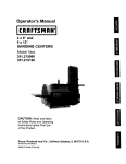
MANUAL
Model No.
319.226560
Serial No.
Model and serial
numbers may be
found on the nam
plate located on the
front of the tool. You
should record both
the model and serial
number and retain it
in a safe place for
future use.
LT/
SANDER
Caution:
• Warranty
Read, understand
and
follow ALL Instructions and rules for
safe
operation
operating
before
this
tool.
. Safety Instructions
" KnowYour Belt/Disc Sander
• Operation
and Maintenance
• Repair Parts
226560102
226560102
Sears,
C
Roebuck
and Co.,
Hoffman
NRTL/C
LR 78936
Estates,
lL 60179
U.S.A.
FULL
ONE-YEAR
WARRANTY
ON
SEARS
BELT
and DISC
SANDER
If this Sears Craftsman Belt and Disc Sander fails due to a defect in material or workmanship
within one year' from the date of purchase, RETURN IT TO THE NEAREST SEARS SERVICE
CENTER INTHE UNITED STATES, and Sears will repair it, free of charge.
If this Belt / Disc Sander is used for cormnercial
for ninety days from the date of purchase.
This warranty
applies
This warranty
gives
from state to state,
Sears,
only while
this product
you specific
Roebuck
and
is in the United
legal rights
Co,, Dept.
817
1.
BEFORE
USING
AVOID
limitations,
DANGEROUS
DO NOT use power
areas or expose them
WA, Hoffman
and
6.
DO
Other
people
Estates,
which
vary
IL 601 79
SANDER
FORCE
THE
TOOL.
a tool to do a job for which
Never
it was not
CONDITIONS.
tools in wet or damp
to rain.
AND
distance
from the work
when tool is operating
rights
designed
It will do a better and safer job by
only using on jobs for which it was
designed.
,
draw
wear
WEAR
keep
FOR
SAFETY.
DO NOT wear
you into moving parts. ALWAYS
non-slip footwear;
tie back long hair.
A FACE
HASK
HASK
IF SANDING
PRODUCES
DUST.
CHILDREN
should
DRESS
loose clothing,
gloves, neckties,
or jewelry
(rings, watches);
they can get caught and
,
AWAY,
NOT
force
possible
4. ALWAYS
keep your woik area clean,
uncluttered
and weU lit. DO NOT work on
floor surfaces that are slippery from
,
sawdust or wax.
VISITORS
will apply
SANDER:
DO NOT use power tools in the presence
of flammable liquids or gases.
KEEP
other
FOR BELT/DISC
BELT/DISC
READ and become
familiar with this
entire instruction
manual. LEARN the
tools applications,
hazards,
2_
THE
this warranty
States.
and you may also have
SAFETY INSTRUCTIONS
m
or rental purposes,
a safe
ALWAYS
remove
the
from the electric
outlet
adjustments,
changing
working
on tool.
area, especially
OR DUST
OPERATION
power
when
pat,s,
10. KEEP GUARDS
IN PLACE
WORKING
ORDER.
SAVE
THESE
INSTRUCTIONS
Page 2
cord plug
making
cleaning
or
AND
IN
SAFETY
11 ALWAYS
INSTRUCTmONS
WEAR
EYE PROTECTION.
Any Sander can throw foreign objects
into the
eyes which could cause permanent
eye damage
ALWAYS Wear Safety
Goggles (not glasses) that comply with ANSI safety standard
Z87o t,
Everyday
eyeglasses
have only impact-resistant
lenses._ they ARE NOT
safety glasses
Safety Goggles
are available
at Sears,
NOTE: Glasses or goggles
not in compliance
with ANSI Z87,1 coiald
WEARYOUR
seriously
12_ AVOID
ACCIDENTAL
Ensure
that
power
before
hurt
you when
switch
is in the
plugging
in the
they
each
adjusting
wrenches
are removed
sander
before turning it on_
the
RECOMMENDED
20_ MAKE
LEAVE
A TOOL
RUNNING
21, DRUGS,
to complete
should
WORKSHOP
STAND
injury could
accidentally
A TOOL.
above
might
or near the toot
stand on the tool to
OVERREACH.
Keep
or odd-shaped
Always
working
TOOLS
keep
tools
clean
WITH
and
24
CARE.
OR
DO NOT operate
tool if
to use
the tool properly,
in good
THESE
pieces
from
OF FEED.
turning.
Feed work
into a
WARNING:
Dust generated from certain
materials can be injuriou s to your health.
Always operate sander in well ventilated
areas and provide for proper dust removal
order
SAVE
or by
blade or cutter against the direction
of
rotation
of the blade or cutter ordyo
proper
footing and balance
at all times. Wear
oil-resistant
r_ubber_soted
footwear.
Keep
floor clear of oil, scrap and other debris
18. MAINTAIN
switches,
22 SECURE ALL WORK.
When practical,
use clamps or a vise to hold work, It is sager
than using your hands and prevents
round
23 , DIRECTION
17. DON'T
or
Serious
result ff the tool tips or you
hit the sander,
DO NOT
store anything
where anyone
reach it
repaired
you are under the i_n£1uence of drugs,
alcohol or medication
that could affect
stop
ON
to
and
CHILDPROOF.
ALGOHOL
3,our ability
16. NEVER
be properly
MEDICATIONS.
UNATTENDED.
Turn the power switch
to "OFF", DO NOT leave too! until it has
come
that
function.
Check for
parts, binding of
By use of padlocks,
master
removing
starter keys_
that accessory,
15, NEVER
part
replaced°
ACCESSORIES.
Using improper
accessories
can be hazardous.
If in doubt,
check the instruction
manual
that comes
with
Before
or other
moving parts, breakage
of parts, mounting
or any other conditions
that may affect its
operation,
A guard or other part that is
damaged
14_ USE ONLY
PARTS.
should be carefully checked
that it will operate
properly
perform
its intended
alignment
of moving
Form
and
from
DAMAGED
use of tool, a guard
is damaged
determine
cord
13, REMOVE
ADJUSTING
TOOLS.
habit of checking
to see that tools
break,
t9, CHECK
STARTING.
the power
"OFF" position
CONTINUED
INSTRUCTIONS
Page 3
SAFETY
INSTRUCTIONS
[] ADDITIONAL
SA!FETY
DO NOT OPERATE
YOUR
INSTALLED
ACCORDING
I .THIS SANDER
WOOD
ONLY.
could
IS DESIGNED
Sanding
result
workpiece_
2 MOUNT
INSTRUCTIONS
SANDER
TO THE
OR WOOD-LIKE
TO SAND
other
injury
1 1, DO
use, the sander
to the bench
USE
this
sander
or move
must
on
the sanding
have
so the belt
DO
USE
size sanding
7 ALWAYS
when
sanding
torn,
to move
Sand
remove
the
before
turning
HOLD
when
the workpiece
awkward
a slip could
only one workpiece
the table
HOLD
when
Solvents
SIDE
firmly
cause
pieces
the sander
could
outer
and other
or belt
"ON?'
assembly
or set-up
the sander is
a hand
the material,
be used
any part
damaged,
properly,
f_'om power
missing,
resuming
18 NEVER
belt sanding,
THE
a soft damp
plastic
sander
parts,
be
or fail in any way, or
fail to perform
shut off switch
supply
and iemove
outlet.
Or failed
operation
YANK THE
out of the receptacle.
disc
of your
parts,
or other
Only
to clean
components
damaged
plastic
dissolve
should
at a time.
on
possibly
damage
any electrical
and when
to clean
cloth
belt or disc.
of the sanding
on the
scrap
wise
missing,
firmly
with
only exception
table, backstop
use solvents
17. SHOULD
hand
the workpiece
disc sanding
using either table when
9, ALWAYS
SAND
ON
DOWNWARD
that
Use only correct
into the sanding
8, ALVVAYS
or discs
the workpiece
operating,
belt mid disc
sandingAvoid
positions
belts
loose,
provide
height.
the workpiece
performed
from
16 NEVER
NOT
that are
drum.
objects
off the
or disc
workpiece,
15 N EVE R perform
layout,
work on the table while
adjusted
pulleys
are damaged,
work
or
supported
or tableiFhe
14. ALWAYS
See directional
not run
Support
sanding
belt is instaUed
does
sand with
is curved
surface,
the tracking
NOT
tile table
belt
at table
unsupported.
clearance
of material
a large
support
the backstop
any
fastened
top or supporting
SURE
5. ALWAYS
during
pieces
sanding
additional
13. DO
the sanding
sand
to be safely
12. WHEN
sander
surfaces
for the
be securely
in the correct
direction
arrow on back of belt,
6
and
AND
a minimum
or less between
NOT
too small
AND
to tip over
properly
backstop
to
SANDER
ASSEMBLED
maintain
of 1/16 inch
or- damage
might result in motor damage_
3 IF THERE
IS ANY TENDENCY
4. MAKE
10 ALWAYS
materials
hoxizontal
surfaces
only. Operating
when mounted
on non-horizontal
machine
FOR BELT/DISC
UNTIL
IT IS COMPLETELY
INSTRUCTIONS.
PRODUCTS
or grinding
in fire,
CONT/NUED
parts
POWER
Keep
plug
Replace
cords
before
CORD
away
from heat, oil and sharp edges.
19 HAVE AN ELECTRICIAN
REPLACE
when using the disc sander Sanding on the
upward side of the disc could cause the
workpiece
to fly up which could be
OR REPAIR
damaged or worn
cords
immediately,
hazardous,
i
SAVE
THESE
INSTRUCTIONS
Page
4
]
SAFETY
INSTRUCTHO.NS
l_ ADDITIONAL
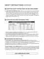
20USE
SAFETY RNSTRUCTIONS
PROPER
When
product
using
EXTENSION
an extension
CORD.
power
and overheating°
length
and nameplate
gauge
number,
The
the heavier
tTJll_lltTJlil|Tt|i___ii
not more
shows
than
_
resulting
heavier
,,
'150'
16
16
14
18
16
14
12
t0
12
16
16
14
12
12
16
14
12
EVENT
cord outdoors,
be sure
that it is acceptable
cords
from
Not Recommended
it is marked
for outdoor
with
the suffix
"W-A"
use
wired,
and in good electrical
condition
Mways
it repaired
by a qualified
person
before using it,
sharp
objects,
excessive
heat
and damp
or wet
areas,
INSTRUCTIONS
OF A blALFUNCTION
OR BREAKDOWN,
grounding
provides
a
Columns
path of least resistance
for electric
current
to reduce the risk of electric
shockThis
is equipped
with an electric
cord having an equipment-grounding
conductor
and a
grounding
plugThe
plug MUST be plugged
into a matching
outlet that is properly
installed
grounded
in accordance
with' A_LL local codes and ordinances
DO
NOT
MODIFY
THE
3-PRONG
PLUG...if
installed by a qualified
electrician,
Improper
can result in a risk of shock,The
conductor
(sometimes,but
the
.....
18
GROUNDING
smaller
i vT
10
extension
on cord
The
CORDS
6
your
your
in loss of
depending
gauger
6
to indicate
condition
the current
size to use
use the next
using 120 volts only)
Total length of cord in feet
25'
50'
100'
Be sure your extension
cord is properly
replace a damaged
extension
cord or have
IN 'THE
is in good
0
("W" in Canada)
i
cord
to carry
in line voltage
;l_:_llt¢l_l--"][t]i'l|l'IO]_}i},:
1
if you are using an extension
Protect
enough
the correct
If in doubt,
t_'];;ll_;[o
, (when
=
extension
a drop
EXTENSION
Rating
than
your
SANDER
the cord
FOR USING
Ampere
FOR BELT/DISC
heavy
will c;mse
below
rating
sure
to use one
cord
table
ampere
m GUIDELINES
Make
cord, be sure
will draw_ An undersized
more
CONTINUED
not always
with
yellow
SAVE
have
the proper
connection
of the equipment-grounding
with insulation
having an outer surface
stripes)
THESE
it will not fit the outlet,
is the equipment
INSTRUCTIONS
Page
5
grounding
tool
and
outlet
conductor
that is green
conductor
I
SAFETY
INSTRUCTIONS
m GROUNDING
USE
ONLY
THAT
INSTRUCTIONS
3-WIRE
THAT
HAVE
PLUGS AND
CONTINUED
EXTENSION
CONTINUED
CORDS
3-PRONG
GROUNDING
3-POLE RECEPTACLES
ACCEPT
THE
TOOL'S
REPAIR
OR REPLACE
VVORN
CORD
DAMAGED
IMMEDIATELY...if
OR
repair or
replacement
of the electric
cord or plug is
ever necessary,
DO NOT
connect
the
equipment-grounding
conductor
to a live
terminal.
PLUG.
ii it i ,,,
_
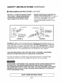
s3_ProngPtug
Grounding
Lug
Make Sure This
Is Connected to a
Known Ground
Grounding Prong
"Properly Grounded
3-Prong Outlet
FIGURE
"_ 2-Prong
Receptacle
FIGURE
A
B
tllllll
FIGURE
(A)...shows
a 3-wire electrical
plug and outlet that has a grounding
conductor
If a
properly
grounded
outlet is not available, an adapter
(FIGURE
B) can be used to temporarily
connect
this plug to a 2-contact
ungrounded
outlet, The adapter
(FIGURE
B) has a rigid lug
extending
from it that MUST be com, lected to a permanent
earth
ground, such as a properly
grounded
outlet box., The Canadian
Electrical
Code prohibits
the use of adapters,
THE
ADAPTER
OUTLET
CAN
If you have
instructions
_/HEN
SHOULD
BE INSTALLED
any doubts as to whether
are unclear; check with
USING
A GROUNDED
BE SURE THAT
THE
AN UNGROUNDED
PROBLEMS
THAT
WITH
A GROUNDED
[
ONLY
BE USED
UNTIL
A PROPERLY
BY A QUALIFIED
TECHNICIAN.
the tool is properly
a qualified
electrician
TOOL
UNGROUNDED
DEVICE
CAN
COULD
CAUSE
AROUND
DEVICES
FUNCTION,
A HAZARD
GROUNDED
grounded
or' if the grounding
or service personnel
OTHER
ARE
UNGROUNDED
IN GOOD
DEVICES,
CONDITION.
YET HAVE INTERNAL
WHEN
BROUGHT
IN
ELECTRICAL
CONTACT
TOOL.
SAVE
THESE
INSTRUCTIONS
Page 6
J
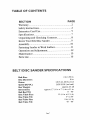
TABLE
OF CONTENTS
SECTION
PAGE
Warranty.
..............................................................
2
Safety Instructions ...............................................
2
Extension Cord Use .............................................
5
Specifications .......................................................
7
UnpacMng and Checking Contents ..................... 8
Know Your Belt/Disc Sander ................................ 9
Assembly. ............................................................
10
Fastening Sander to Work Surface ....................... 11
Operation and Adjustment ..................................
12
Maintenance .......................................................
15
Parts List .............................................................
16
BELT/DiSC
Belt
SANDER
Size:
Disc Diameter:
Motor:
Speed (R.P.M.):
Net Weight:
Dimensions:
Belt
Bed
Tilt:
Disc Table
Size:
Disc Table
Tilt:
Bed
Table
Size:
Belt
Table
Tilt:
SPECIFICATIONS
4 in, x 36 in.
8 in.
120VAC, 60 Hz, 6oOA
3450 R EM (no load)
approx. 43 LB
approxo 17 t/2 in. x 7 t/2 in. x 11 in.
0 o . 90 °
10 i/2 in_x 6 1/4 in,
0 ° to450
6 Lq.x 4 in.
45" -90'
Page
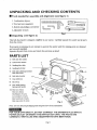
UNPACKING
_[ Tools
needed
for
1, Combination
2_Two
hex
3. Slotted
AND
CHECKING
assembly
and
alignment:
CONTENTS
(see
figure
t)
Square
keys (supplied)
and phillips
4_Adjustable
screwdriver
wrench
Fig. I
Bi Unpacking
(see figure
This belt disc/sander
from the carton.
If any parts
and correctly
Separate
is shipped
are missing,
2)
complete
do not attempt
in one carton
to operate
Carefiflly unpack
the sander
until
the sander and all parts
the missing
parts
are obtained
installed.
all parts
from
carton
and
check
for each
item as listed:
PARTS LIST
1)
Belt and disc sander
6
4
Hex head bolt (3 each)
Hex cap screw
Note:
Do not discard
FOR YOUR
OVeN
POWER
OUTLET
CORRECTLY
10
(3 each)
packaging
Fig. 2
until
aU parts
have
been
assembled.
SAFETY,
DO NOT CONNECT
THE SANDER'S
PLUG INTO
OR INSERT
THE SWITCH
KEY UNTIL
THE PARTS ARE
INSTALLED
AND
ADJUSTMENTS
Page 8
HAVE
BEEN
MADE.
A
KNOW
YOUR
BELT/DmSC
SANDER
Dust deflector
BACKSTOP
belt
disc
"
DISC
Sanding
---- Belt bed
plate
Sanding
TABLE
---
Sanding
BELT
TABLE
Idler
drum
--- Disc guard
ON/OFF switch
with key
Base mounting
hole
Fig. 3
KEY GUIDES
FOR PROFESSIONAL
DISC TABLE:
is used to support
sander in vertical position.
RESULTS
workpiece
when
using
sanding
disc or when
using
belt
BELT TABLE:
is used to support
workpiece
when edge sanding
on the belt only,
BACKSTOP:
holds the workpiece
when using sander in horizontal
position,
Can be removed
when sanding
operation
requires
use of the entire belt.
Tension
lever
Tracking
knob
Holding
Adjusting
Tilt lock
Backstop
screw
bracket
locking
Bed locking
Belt table
adjust knob
Drive
bracket
Drive
Spring
belt
Dust
Drive belt
adjusting
hole
Power
2 Hex keys
(5 & 6 mm)
screw
belt housing
load handle
chute
cord
Drive belt
housing
cover
Fig. 4
TO AVOID INJURY FROM ACCIDENTAL
PLUG FROM
POVVER
SOURCE
OUTLET
::
.::
.....
STARTING,
TURN SWITCH
"OFF" AND
BEFORE
MAKING
ANY ADJUSTMENTS.
Page 9
REMOVE
_:
.,
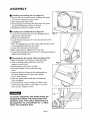
ASSEMBLY
Ill Installing
the sanding
1, Remove
the two screws
and
remove
sanding
2_Wipe sanding
3, Peel backing
disc (see figure
from the sanding
disc guard
5)
disc guard
plate.
disc plate clean.
from sanding
disc, align disc with
plate
and press saxlding disc firmly on to plate,
4, Reinstall disc guard and tighten screws_
[] Installing
the sanding
1 Loosen the bed locking
tighten
2, Release
3. Locate
bed locking
the tension
belt (see figure
6)
screw, raise sanding
bed
arrow
belt
on the smooth
over the
drums
bed
tighten
locking
screw,
bed locking
screw
mi Mounting
the
lower
disc sander
bed
table
1.Align the bracket
tO the bottom
2_ Insert a locking
washer, followed
side of the
with
arrow pointing
toward the dust chute,
5, Center belt correctly
on both drams,,
6, Slide tension
level to tighten
belt to the
7 Loosen
Fig. 5
screw
lever.
the directional
sanding belt,
4, Place the sanding
45",
the directional
bed_
to horizontal
(see
figures
position,
7,8)
of the disc table.
by the flat
Fig. 6
washer, on each screw,
3 Fasten bracket
with screws to table.
4. Insert flat washer
on disc table adjusting
knob.
5. install
the
the table
table
by lining
bracket
with
up the indexing
the pivot
hole
pin on
on the
frame.. Hold in place.
6 Insert the spring load handle into tile threaded
hole and tighten
7 Loosen the three screws
holding the table to the
bracket
from
and adjust
the disc.
TO AVOID
FINGERS
SANDING
table
Tighten
TRAPPING
BETWEEN
DISC,
THE
so that edge
is I/I6
inch
Fig. 7,8
screws,
THE
THE
WORK
TABLE
TABLE
BE ADJUSTED
TO A MAXIMUM
FROM THE SANDING
DISC.
PIECE
AND
EDGE
OR
THE
SHOULD
OF 1/L6 INCH
Page t0
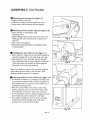
ASSENBL¥
CONTINUED
B Hounting
the backstop
(see figure 9)
l Align backstop with hole
2, Install lock washer
and flat washer
on screw
3 insert
screw
into backstop
hole and
tighten,
Mounting
the belt sander table (see figure 10)
1, Insert washer on belt sander table
fastening screv¢.
ZAlign holding bracket index and screw hole with
indexing and screw hole located on side of the
belt bed,
3_Insert screw and tighten.
4_Slide table adjusting bracket
Lock and adjust.
@
Fig. 9
on holding brackeL
8la Installing the dust deflector
(see figure I I)
1, Insert deflector index pins in the tracks located on
the side housing of the dust collecting assembly.
2. Slide upward to lock vertically, Li_ up and pull
downward allowing the dust collector to slide out
of the way when not needed or when using the
disc table at the end of the belt bed.
Note: Dust deflector
can not be in vertical
when using the disc table on the belt bed
deflector
must be lowered
or removed,
IFastening
sander to work surface
1 ,To mount your sander in a permanent
as a sturdy workbench,
bolt the base
Fig. i 0
position
Dust
(see figure 12)
location
such
of sander
to a
solid workbench
top The base of the sander has 2
predrilled
mounting
holes,
2 Place the sander where
you desire on the work
Fig. It
surface, marl( the holes on the work surface, drill
3/8 inch holes. Use bolts, washer; nuts to secure.
3. ff the workbench
the workbench
4.Your
sander
surfaces
mounted
moves or shakes during operation,
must be fastened
to the floor.
is designed
to be used
only. Motor damage
on a non-horizontal
on horizontal
may result
surface
when
¢
Fig. 12
Page l t
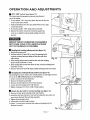
OPERATION
AND
ADJUSTMENTS
[] ON t OFF switch (see figure l3)
The keyed switch is hutended to prevent unauthorized
use of the sander:
1•To mm sander "ON" insert the yellow key into the key slot
in the center of the switch
Z Push key firmly into the slot, then push switch to the r_,ht
to start the sander.
3_ To turn the sander
4. Remove
"OFF" push switch to the left.,
the yellow switch
come to a complete
key when
the sander has
stop by gently pulling it forward
and out,
Fig. 13
REMOVE THE I(_'Y WHENEVER
THE SANDER IS
NOT IN USE. PLACE IT IN A SAFE PLACE AND
OUT OF THE R_.ACH OF CHILDREN,
[]
Sanding belt tracking adjustment
(see figure 14)
1. Plug in the power cord,
2. _
the switch ON and OFF m see if the sanding beat is
correctly centered
roller' drums_
3, ff the sanding
knob counter
and not sliding off the idler and drive
Fig. i 4
belt moves toward the disc, mm the traddng
d_..k'wise a/4 ram.
4_ If the sanding belt moves away from the disc, turn the tracking knob
cl_
V4 turn
5 'Dam the switch OFT and OFF again, readju_
tracldng knob ff neces._r-fi
Im Changing
(see figure
the sanding
belt bed position
I5)
The sanding bed can be used in the vertical position or any angle between,
To use in the full vertical position, do the following:
1, Lower or remove the dust deflector
2. Remove
3,, Remove
the backstop assembly
the belt table from the belt bed location..
Fig. 15
4_ Loosen the bed locking screw with h_,_ key
5_ Tighten
lm Attach
l__ldng scTew when
at Fall vertical position,,
the disc table for vertical
sanding.
(see figure
i 6)
1. Remove the disc table assembly (table and bracke0,
2. Attach the disc table bracket to the belt bed u_.ng the same pilot and
screw holes that held the belt table assembly.
3. Tighten all mounting screws.
4. Adjust table to desired angle position
5..Enst_e iA6 indn space between
Readjust
table edge and sanding belt bed
if needed,
Fig. 16
Page 12
OPEF T ON
J
AND
CONTINUED
ADJUSTNENT$
Squaring the tables (see figure 17)
lb ensure accurate end sanding the wade tables mt_ be sqtmre to the
s_mding snarlhcesprior to using the tables for disc sanding, belt sanding,
or vertiml belt sanding
I Adjust tame you will be using to be 90" with the sanding sun'ace
2 Using a combination
square, place one end on the table with the
rifler end against the sanding surface, Check that the table is
90" m the s,mding surface
3 If the table is not 90" to the sanding satrface, loosen the table lock
knob, adjust table, tighten knob and recheck with square,
[] Squaring the backstop
The backstop must be square to the minding belt when us_mgthe belt sander
in a horizontal position,To Imep the wotkpiece from being carried along the belt:
I, Ensure that the sanding belt is tight, chedc the tension lever.
2oPlace the combination square on the belt with the ruler against the backstop
3. Adjust by loosening backstop locking screw, square backstop,
4,11ghten backstop locking scaev_,
!
Fig. 17
Dust chute
The dust chute can be easily connected
to a large diameter
shop vacuum
hose
BASIC: SANDING
OPERATIONS
USING
THE
SANDING
BELT
AVOID
INJURY
FROM SLIPS, JAMS, OR THROWN
PIECES, SQUARE
TO 90 ° AND ADJUST
THE
BACKSTOP
TO CLEAR THE SANDING
BELT A
MAXIMUM
OF Ill6 INCH.
REVIEW
INSTRUCTION
MANUAL
FOR
CORRECT
Fig. 18
ADJUSTMENTS.
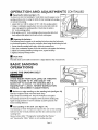
Im Surface or edge sanding on the sanding belt (see figure 18)
Hold the wad€piece finr_ withbothhandsKeep
fingers away from sanding belt Keep the waft€piece end against
the baclcstop and move the wad€piece slowly across the sanding belt
Apply enough pressure to remove material; excessive pressure will
reduce sanding efficiency.
End sanding
on the belt
End sanding
of wide workpieces
belt bed in the vertical
position
sanding
(see figure
! 9)
requires
the use of the sanding
and the disc table moved to the
belt
Review Sections titled: "Changing the Sanding Belt Bed Position"
and "Squaring the Tables" before an end sanding operation
Page 13
Fig. 19
BASIC
[]
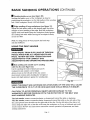
Sanding
Sanding
SANDING
inside
the inside
positioning
belt, Hold
OPERATIONS
curves (see figure 20)
curve
of' the workpiece
is done
the workpiece
on the idler pulley
workpiece
firmly with both hands,
Edge sanding
CONTINUED
of long workpieces
by
of' the
sanding
(see figure
21 )
Adjust the belt sander table to the desired angle for either
straight or bevel sanding
of the edge. Hold the workpiece
tightly with both hands.. Keep the w0rkpiece
firmly
the sanding bett table while moving the workpiece
across the table,
Note: For long pieces
and dust deflector,
USING
THE
of wood,
DISC
INJURY
PIECES,
MADE.
HAKE
SURE ALL
REVIEW
SECTION
ADJUSTMENTS
FROM
FOR
AND
End sanding
the back
Fig. 20
stop
SANDER
AVOID
ADJUSTMENTS"
remove
against
slowly
SLIPS,
JAMS
OR THROWN
ADJUSTMENTS
"OPERATION
CORRECT
DISC
OPERATING
and outside
ARE
AND
Fig. 21
PROCEDURES.
curve sanding
with the disc (see figure 22)
Use for sanding
the ends of small
and narrow
workpieces
and outside
cur_¢ed edges
Always work on the teft side of the disc center
(downward
rotation
side), holding the workpiece
firmly with light pressure
against the sanding
disc°
Fig. 22
USING THE RIGHT
SIDE (UPWARD
ROTATION
THE WORKPtECE
TO FLY UP OR KICK BACK
CAUTION:
TO
AVOID
PERSONAL
WORKPIECE,
BECOME
FAMILIAR
DISC SANDING
SURFACES.
The
The
belt
disc
disc and
sander
sander
upward
rotates
rotates
from
the
INJURY
WITH
counteivtockwise,
counterclockwise,
table
on the
SIDE) OF THE DISC
AND COULD
RESULT
AND/OR
THE
DAMAGE
ROTATION
TO
OF THE
WILL
CAUSE
IN INJURY.
THE
BELT
AND
or downward
toward
the table or backstop.
downward
toward
the table on the left side of the
right
side of the disc. Use the
left side of the disc at all
times; using the right side of the disc will cause the workpiece
to fly up or kickback
and could
r'esult in injury_ Review
this instr__lction manual for correct
operation,
adjustments,
and basic
sanding
operations.
Page 14
MAINTENANCE
FOR YOUR SAFETY, TURN SWITCH
"OFF"
AND REMOVE THE POWER CORD FROM
THE
ELECTRICAL
OUTLET
3 Adjust the tension ot tlle belt by putting a
slotted screwdriver
in the bracing sloE.
Pushing up on the screwdriver will tighten
the tension of the belt between the
pulleys.
4 Tighten all 3 screws.
5. Test belt tension by Squeezing both sides
of the belt. It"properly adjusted, the belt
should "give" about 1/-i inch
6. Carefully reinstall the drive belt housing
cover; inset, and tighten screw
BEFORE
ADJUSTING
OR PERFORMING
MAINTENANCE
ON "fOUR SANDER.
TO AVOID
ELECTROCUTION
OR FIRE,
ALL REPAIRS
TO THE ELECTRICAL
COMPONENTS
SHOULD
ONLY
BY QUALIFIED
TECHNICIANS.
BE DONE
SERVICE
Before each use check for parts that are damaged, missing, or worn; check for alignment of
moving parts, binding of moving parts,
improper mounting, or any other' conditions
that may affect the sander operation
Should
any of these conditions exist, do not use the
sander until properly repaired or parts
replaced£requentIy
blow or vacuum
dust
from all sanding parts and motor housing
Note: Excessive tightness on the pulley belt
will cause increased noise and motor overload
Premature failure will occur' ff belt is too loose
B LUBRICATION
Ball bearings are grease packed at the
factory and require no further lubrication.
Sleeve bearings on both ends of the idler
pulley should be oiled with 3 drops of 30
weight oil after each 10 hours of operation.
Use a spray lubricant to ensure smooth
operation on all moving table parts.
Fig. 23
@
A
DRIVE BELT (see figure 23 A,B)
To adjust the drive belt t_bllow these steps:
1.. Remove the drive belt housing cover.
2 Loosen 3 screws aUowing pulleys to slip
Drive belt should be seated correctly in
the motor pulley and the drive pulley.
Page 15
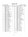
PARTS
BELT/DISC
LIST
MODEL
SANDER
Key
Part Number
|
2
3
4
5
6
7
8
9
IO
11
12
13
14
15
16
I7
18
19
20
2l
22
23
24
25
26
27
28
29
30
31
32
33
34
35
36
3_
38
39
40
4t
42
43
44
45
46
4"
226560001
226560002
226560003
226560004
226560005
226560006
226560007
226560008
226560009
226560010
226560011
226560012
226560013
226560014
226560015
226560016
226560017
226560018
226560019
226560020
226560021
226560022
226560023
226560024
226560025
226560026
226560027
226560028
226560029
226560030
22656003. l
226560032
226560033
226560034
226560035
226560036
226560037
226560038
226560039
226560040
22656004 i
226560042
226560043
226560044
226560045
226560046
226560047
Description
Knob
Spring base
Spring index
Bed
Screw hex 6xl4mm
Lockwvaslaer 6
"Washer
Backstop
Bumper
Screw pan hd 5xlOmm
Lockwasher 5
Drum idler
Screw socket set M8xl0
Cap bearing
Bearing w/felt washer
Spacer bearing
Switch housing
Screw pan hd MSxl4mm
Sanding belt 4"x36"
Switch key (yellow)
Locking switch
Lead
Screw pan cross
Switch box cover
Capacitor' 30UF
Sanding disc 8"
Screw box soc cap M6x12
Lockwasher ext 6
Disc-plate
Screw pan lad st 2x13
Disc guard
Disc shroud
Dust housing
Dust deflector
Disc table
Disc table bntcket
Spring load la:mdle
LocRwasher ext 5
index scale
Cord w/plug
Screw pan hd M5x8
Dust plate
Motor
Connector wire
Hex nut M6
Base
Screw pan hd MSx6
Quantity
t
2
t
1
2
3
3
1
i
3
2
I
2
1
4
L
I
2
t
i
I
1
t
1
1
t
t
1
I
4
[
I
I
t
[
I
l
6
t
l
t
l
i
l
1
l
3
Key
48
49
5O
51
52
53
54
55
56
57
58
59
60
61
62
63
64
65
66
67
68
69
70
71
72
73
74
75
76
77
78
V9
80
8l
82
83
84
85
86
88
89 "
90 *
99 "
10t)"
101"
102"
Part
226560048
226560049
226560050
22656005 l
226560052
226560053
226560054
226560055
226560¢)56
226560057
226560058
226560059
226560060
22656O061
226560062
226560063
226560064
226560065
22656O066
226560067
226560068
226560069
226560O70
22656007 l
226560072
226560073
22656¢)074
226560075
226560076
22656O077
22656O078
226560079
226560080
226560081
226560082
226560083
226560084
226560085
22656{)086
226560088
22656O089
226560090
226560099
226560100
22656{) 101
22656O i O2
' Not Shown
Page 16
Number
NO. 39 i.226560
Description
Quan tit),
Base cover plate
Drive belt
Screw fiat cross ?¢t5x14
Washer countersink
1
I
2
t
Pulley
Screw hex soc cap M6x20
Loclcwasber
helical 6
Lockwasher t'telical 6
Washer countersink
1
1
1
I
l
Pulley
Screw hex soc cap M5x25
Suppor't bearing
Nut square
M8
Screw hex soc cap M8x30
Screw flat cross M5xl0
Belt cover
i
1
1
I
1
I
1
Support bed
Retaining ring 12
Knob
Ddvc shaft
'Tilt lock
1
4
1
1
1
Index pointer'
Screw pan hd M3x4
Adjusting pointer
Screw hcx soc cap M6xl0
Screw pan hd M5x16
Wedge
Guide dr _.m_
Bed bed table
Side bt_tcket
Washer 5
Rubber w:tsher
1
1
I
1
1
!
1
I
1
2
1
Spacer' lever knob
Spacer
Idler shaft
Washer
1
1
1
2
Axle ring 28
idler drum
2
1
Tension spring
Plastic washer
1
1
Hex key 5mm
Hcx kt:y 6ram
Name plate
Warning label
Rotation label
Owner s manual
t
t
l
I
2
l
g
/
75
73 74
26
67
53
So
34
4g
33
36
_42
43
48
Page I7
39
/I:RRFTSMRN +
OWNER'S
BE[ r/DISC
MANUAL
SERVICE
MODEL NO.
319.226560
HOW TO ORDER
REPAIR PARTS
To Call
Toll Free
For Service:
i -800-4-REPAIR
( i -800-473- 7247)
For Parts:
Now that you have purchased your Belt/Disc Sander,
should a need ever exist for repair parts or service,
simply contact any Sears Service Center and most
Sears stores.. Be sttre to provide all pertinent facts
when you ca_ or visit
The model munber of yotu' Belt and Disc Sander
will be found on the plate attached to your sander
WHEN ORDERING REPAIR PARI'K ALWAYS
GIVE II_IE FOLLOWING INFOP_vlATION,
• PART
NUMBER
- MODEL NUMBER
31922656O
• PART
• NAME
DESCRIPTION
OF ITEM
BELT/DISC
SAI',_DER
AI1repair parts listed are available for inunediate
purchase or special order when you visit your nearest
Sears Service Center', or the Service Dep_,ment
at
most Sears stores. To order pa_xs by phone, call the
tol! free parts number' listed to the left
1-800-366-PART
(1-800-366-7278)
Sears,
3 t9226560t02
Roebuck
and Co., Hoffman
Estates,
IL 60179
U.S.A.
496
Piinted in China