1
uni
~n@
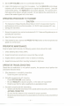
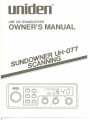
UHF CB TRANSCEIVER
OWNER'S
MANUAL
I
uDden
UH-O77
11
USCAN U
T.SO
GS. £
MEM
U OS ~
TX
I rnEI
@ID
l 1 "
IMEMI-,
IDUPIICAI1051
1- I
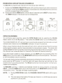
DESCRIPTION
Your UNIDENModel SUNDOWNER UH-O77 represents the most advanced Mobile Station type radio ever designed for use in the Citizens Band Radio Service. Itwilloperate on
any of the 40 frequencies designated as citizens band channels by the Department of
Communications. Your Model SUNDOWNER UH-O77features a frequency synthesizing
circuit with PHASE LOCK LOOP techniques to assure ultraprecise Frequency control.
This radio has been Type Accepted and Type Certified by the D.O.C.
WARNING
Before transmitting with your transceiver, you must obtain a Department of Communications (D.O.C.) Citizens Radio Licence. Obtain an application form from the
D.O.C.Beforecompletingthe formyou shouldreadthe conditionsgoverningthe licensingand operationoftheC.R.S. (D.O.C. brochure RB250). This brochure also
can be obtained fromthe D.O.C.Aftercompletingthe applicationform,mailitwith
the appropriate fee to the Superintendant Regulatory of Licensing in the State or
territory"in which the station will be operated.
CHANNEL INFORMATION
This radio has been designed to provide high level performance in the Citizens Band Radio
Service, which is comprised of the following frequency assignments:
Channel
1
2
3
4
5
6
7
8
9
10
11
12
13
14
Channel Frequency
in MHz
476.425
476.450
476.475
476.500
476.525
476.550
476.575
476.600
476.625
476.650
476.675
476.700
476.725
476.750
Channel
15
16
17
18
19
20
21
22
23
24
25
26
27
28
Channel Frequency
in MHz
476.775
476.800
476.825
476.850
476.875
476.900
476.925
476.950
476.975
477.000
477.025
477.050
477.075
477.100
Channel
29
30
31
32
33
34
35
36
37
38
39
40
Channel Frequency
inMHz
477.125
477.150
477.175
477.200
477.225
477.250
477.275
477.300
477.325
477.350
477.375
477.400
DUPLEX OPERATING FREQUENCIES
CHANNEL
CH1
CH2
CH3
CH4
RX
476.425 MHz 477.175
476.450"
477.200
476.475"
477.225
476.500"
477.250
CHANNEL
TX
MHz
..
..
..
CH5
CH6
CH7
CH8
(CH31)
(CH32)
(CH33)
(CH34)
-2-
TX
RX
476.525
476.550
476.575
476.600
MHz 477.275
"
477.300
" 477.325
"
477.350
MHz
..
..
..
(CH35)
(CH36)
(CH37)
(CH38)
INSTALLATION
MOBILE STATION INSTALLATION
Plan the location of the transceiver and microphone bracket before starting the installation. Select a location that is convenient for operation and does not interfere with the driver
or passenger in the vehicle. The radio should be securely fastened to some solid face, using the mounting bracket and self-tapping screws which are provided.
MOBILE STATION ANTENNA
Since the maximum allowable power output of the transmitter is limited by the D.O.C., the
antenna is a very important factor affecting transmission distance. It is for this reason that
we strongly recommend that you install only a quality antenna in your new citizens band
system. You have just purchased a superior transceiver. Don't diminish its performance
by installing an inferior antenna.
Only a properly matched antenna system will allow maximum power transferfrom the 50ohm transmission line to the radiating element. Your Uniden dealer is qualified to assist
you in the selection of the proper antenna to meet your application requirements.
For automobile installation, the whip antenna may be used with good effect. The most efficient and practical installation is a full quarter wave whip antenna mounted on the rear
deck or fender top midway between the rear window and bumper.
A short "loaded" whip antenna is more convenient to install on your automobile, although
the efficiency is less than a full quarter wave whip antenna.
For marine installation, consult your dealerfor information regarding an adequate grounding system and prevention of electrolysis between fittings in the hull and water.
GROUND SYSTEM
Connect the red DC power cord from the transceiver to the positive, or (+), battery terminal
or other convenient point and connect the black power lead to the chassis or vehicle frame,
or (-) battery terminal.
SELCALL
SELCALL (Selective Calling) is a special Squelch System which quiets your receiver until
it receives an Encoded signal from another set which matches the one installed in your set.
This means your set will remain quiet and not receive idle chit chat or other signals until the
station you want to hear calls.
SELCALL is not initially installed in your set (each one has to be individually programmed)
but may be purchased as an option.
OPERATING PROCEDURE TO RECEIVE
1. Be sure that the power source, antenna and microphone are connected to the proper
connectors before going to the next steps.
2. Turn the unit ON by rotating the OFF/VOLUME
Control clockwise.
3. Set the CHANNEL SELECTOR switch to the desired channel.
-3-
4. Set the OFF/VOLUME
Control to a comfortable listening level.
5. Listen to the background noise from the speaker. Turn the SQUELCH control slowly
clockwise until the noise JUST disappears (no signal should be present). Leave the
control at this setting. The SQUELCH is now properly adjusted. The receiver will remain quiet until a signal is actually received. Do not advance the control too far, or
some of the weaker signals will not be heard.
OPERATING PROCEDURE TO TRANSMIT
CAUTION
-
The transceiver Voltage Standing Wave Ratio (V.S.W.R.) measurement must be
performed prior to the use of the transmitter. A V.S.W.R. ratio in excess of 2:1 may
damage the transmitter.
1. Be sure the operator has read and understands D.G.C. Rules and Regulations prior to
operating the transmitter.
2. Select the desired channel.
3. If the channel is clear, depress the PRESS-TO' TALK switch on the microphone and
speak in a normal voice.
PREVENTIVE MAINTENANCE
At six to twelve month intervals, the following system checks should be made:
1. Check Standing Wave Ratio (SWR).
2. Inspect all electrical connections to ensure that they are tight.
3. Inspect antenna coaxial cable for wear or breaks on shielding.
4. Inspect all screws and other mounting hardware for tightness.
OPERATOR TROUBLESHOOTING
Should the unit malfunction or not perform properly, the operator should perform the
procedures indicated below:
1. If the transceiver is completely inoperative.
* Check the power cord and fuse.
2. If trouble is experienced with receiving.
* Check OFF/VOLUME control setting.
* Be sure SQUELCH is adjusted properly. Is the radio over-squelched?
* Check to see that the radio is switched to an operational mode.
3. If trouble is experienced with transmitting.
*
*
*
Checkto seethat the transmission line (coaxialcable) issecurely connectedto the
ANTENNA CONNECTOR.
Be sure that the antenna is fully extended for proper operation.
Besure that alltransmission line(coaxial cable)connections are secure andfree of
corrosion.
-4-
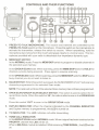
1
2
1. PRESS- TO-TALK MICROPHONE: The receive and transmit are controlled by the
PRESS- TO-TALK switch on the microphone. Press the switch on the microphone to
activate the transmitter; release the switch to receive. When transmitting, hold the
microphone two inches from the mouth and speak clearly in a normal voice. The microphone provided with your radio is detachable Iow impedance dynamic type.
2. MEM/SKIP SWITCH:
In the NORMAL mode: Press the MEM/SKIP switch to program or disable channels in
the selected scan memory.
In the GROUP SCAN mode: When scanning, press the MEM/SKIP switch to HOLD the
channel currently being scanned. Press again to resume scanning.
in the OPEN SCAN mode: When scanning, press the MEM/SKIP switch to SKIP over a
busy channel you do not wish to listen to.
3. SCAN SWITCH: When this switch is pressed, the SUNDOWNER UH-O77 will scan any
channels programmed in the selected Scan mode.
NOTE: The radio will not Scan if the selected Scan memory has not been programmed.
4. OPEN SCAN/GROUP SCAN SELECT SWITCH: This switch is used to select the required Scan mode. When this switch is 'IN', the radio is able to scan in the OPEN SCAN
mode.
Press this switch 'our
to scan in the GROUP SCAN mode.
5. DUPLEX INDICATOR: When the channel indicated by the CHANNEL INDICATOR
and Duplex memory is programmed, this LED is turned on.
6. TX INDICATOR: This LED indicates red while transmitting.
7. TONE CALL INDICATOR:
In the GROUP SCAN mode & NORMAL mode: When a signal has been received on the
PRIORITY channel this LED will be on.
When a SELCALL module is installed: While receiving TONE SIGNAL, this LED will be
on.
-5-
8.
9.
10.
RX INDICATOR: Lights during the receive mode whenever a station is being received, or whenever the SQUELCH control is adjusted fully counter clockwise.
GROUP SCAN INDICATOR: Lights when the GROUP SCAN mode is selected.
MEMORY INDICATOR:
In the normal mode (SCAN switch OUT): lights if the channel indicated by the CHANNEL INDICATOR and selected by the CHANNEL SELECTOR switch is programmed
into the selected scan memory.
11.
OPEN SCAN INDICATOR: Lights when the OPEN SCAN mode is selected.
12.
CHANNEL INDICATOR: LED indicates the channel number in use.
During NORMAL Mode: Displays the channel selected by the CHANNEL SELECTOR Switch.
During SCAN Mode: Displays the channel currently being scanned. Channel number changes every 0.07 second.
13.
FRONT MICROPHONE SOCKET
14.
OFF/VOLUME CONTROL: Turn clockwise to apply power to the radio and to set the
audio volume to the desired listening level. Turn fully counterclockwise to turn the
radio OFF.
15.
SQUELCH CONTROL: This SQUELCH Control is rotated to cut off or eliminates
received background noise in the absence of an incoming signal. For maximum receiva sensitivity, it is desired that the control be rotated only to this point where the receive background noise or ambient background noise is eliminated. Turn the control
fully counterclockwise, then slowly rotate clockwise until the receive noise disappears. Any signal to be heard must now be slightly stronger than the average received noise. Further clockwise rotation will increase the threshold level which a
signal must overcome in order to be heard. Only strong signals will be heard at the
maximum clockwise setting.
16.
MEMORY SWITCH:
In the NORMAL mode: Press the MEM switch to program or disable channels in the
selected scan memory.
In the GROUP SCAN mode: When scanning, press the MEM switch to HOLD the
channel currently being scanned. Press again to resume scanning.
In the OPEN SCAN mode: When scanning, press the MEM switch to SKIP over a
busy channel you do not wish to listen to.
17.
DUPLEX SWITCH: To program semi-duplex operation for channel 1 through channel8. Select the channel you would like to use as repeater channel (check your local
repeater station frequency first) and push the DUP switch and then DUP indicator will
turn on. Select next repeater channel and push the DUP switch again and so on. To
put the channel back to normal simplex operation, just select the DUPLEX programmed channel by channel selector and push the switch so that the DUP indicator
turns off to indicate that channel is no longer repeater frequency off-set channel. CH
1 through CH 8 are programmable for the repeater operation.
-6-
18.
TONE CALL SWITCH: This switch is reserved for optionalSELCALL
operation.
Push the T. CALL switch, (when this action is taken, TX indicator will flash), then,
TONE SIGNAL will be generated and it opens the Squelch of the other units which
have the same tone squelch function.
19. TONE SQUELCH SWITCH: This switch is reserved for optional SELCALL operation.
Push the T.SQ switch while receiving the TONE SIGNAL. Then, the Circuit of the
SQUELCH is automatically opened.
20.
CHANNEL SELECTOR SWITCH: This switch selects the desired channel for transmission and reception.
Ex1.SP
- POW!lR +
~
ANT.
@
21.
EXTERNAL SPEAKER: The External Speaker Jack is used for remote receiver
monitoring. The external speaker should have a-ohm impedance and be rated to
handle at least 4.0 watts. When the external speaker is plugged in, the internal
speaker is automatically disconnected.
22.
POWER: This jack permits connection of the D.C. power to the transceiver.
cord is supplied with the radio.
23.
ANTENNA CONNECTOR: This female connector permits connection of the transmission line cable male connector (M-Type) to the transceiver.
A power
Memory Backup
Channels maintained in the SUNDOWNER UH-077 memory are protected from loss by a
built-in capacitor which protects the memory for up to 12 hours when you disconnect the
DC Power Cable.
SERVICING YOUR TRANSCEIVER
The technical information, diagrams and charts will be supplied upon request.
It is the user's responsibility to see that this radio is operating at all times in accordance with
the D.O.C. Citizens Radio Service regulations.
We highly recommend that you consult a qualified radiotelephone technician for the servicing and alignment of this UHF CB radio product.
Please refer to the WARNING information contained in the 2nd page of this Owner's Manual.
(NOTE: When ordering parts, it is essential to specify the correct model number and serial
number of the unit.)
-7-
OPERATING INSTRUCTIONS
NORMAL OPERATION
RECEIVE OPERATING PROCEDURE
1. Connect the 13.8 Volt power lead, microphone and antenna.
2. Select the NORMAL mode by selecting the SCAN switch (3) to the 'OUT' position.
3. Rotate the SQUELCH control (15) fully counterclockwise.
4. Switch the radio on by turning the OFF/VOLUME control (14) clockwise and adjust for
a comfortable volume level, and adjust for a comfortable squelch level.
5. Rotate the CHANNEL SELECTOR switch (20) to select the required channel.
TRANSMITTING
To transmit, depress the PRESS- TO- TALK switch (1) on the microphone. Hold the microphone 5-10 cm from your mouth and slightly to one side so that your voice does not project
directly into the microphone (this provides best results). Speak at a normal level. Never
raise your voice or shout into the microphone. Whenever the PTT switch is pressed, the TX
indicator (6) will light.
PROGRAMMING SCAN CHANNELS
When the radio is initially powered up, there will not be any channels programmed into the
Group Scan Memory.
To program scan channels into the Group Scan memory, use the following procedure:
1. Select the NORMAL mode by selecting the SCAN switch (3) to the 'OUT' position.
2. Select the GROUP SCAN Mode by selecting the OS/GS Select switch (4) to the 'OUT'
position. The GS indicator (9) should be lit.
3. Rotate the CHANNEL SELECTOR switch (20) until the channel you wish to scan is displayed. Note that the MEM indicator (10) should NOT be lit, indicating that this channel
is not currently programmed into the GROUP SCAN memory.
4. Press and hold the MEM switch (16) for about 1 second until a BE.EP is heard. The
MEM indicator (10) should now be lit indicating that the channel is now programmed into the memory.
5. Continue steps 3 and 4 to program all the channels you wish to scan.
Select
NORMAL
GROUP SCAN
SCAN
OS
[DJ
Select
Select
CHANNEL
unlden
UH-077
+ r;u:
-x.J ~ '°;1+
-x.J
-8-
Install
CHANNEL
MEM
DJ
l } t
- .
BEEP!
'MEM'Light
ON
I
,
1~,1
-~-~' -I LII
REMOVING GROUP SCAN CHANNELS
To DELETE a programmed channel from the Group Scan Memory.
1. Rotate the CHANNEL SELECTOR switch (20) until the channel you wish to remove is
displayed. Note that the MEM indicator (10) should be lit, indicating that this channel is
currently programmed in the memory.
2. Press and hold the MEM switch (16) for about 2 seconds until a BEEP is heard twice.
The MEM indicator (10) should now be extinguished.
Select
Select
NORMAL
Remove
CHANNEl
'MEM'Light
OFF
unlaen
SCAN
(DJ
Select
CHANNEl
UH-O77
I
DJ
,GOl,
-X .ll I
-X
.i I 1'°;+ t
))
--"I
11/l'-l
-(QiJ
-
t
BEEP!"
OPEN SCANNING
To commence open scanning, select the OPEN SCAN mode by selecting the OS/GS
Select switch (4) to the IN position. Then select the SCAN switch (3) to the IN position.
The SUNDOWNER UH-077 will commence scanning the programmed channels, and will
indicate each channel on the CHANNEL indicator (12) as it is scanned.
When a busy channel is found, the radio will 'lock' onto it, and will remain there for as long
as the signal is present, and for 3 seconds after the transmission ceases. This allows the
SUNDOWNER UH-077 to hold the channel during short breaks in the conversation. Once
the channel has remained clear for 3 seconds, the radio will resume scanning.
If you don't wish to listen to a busy channel, you can SKIP over it by pressing either the
MEM switch (16) on the radio, or the MEMlSKIP switch (2) on the microphone. The receiver will immediately resume scanning.
To manually hold a channel indefinitely (temporarily inhibiting the scan function), momentarily press the PTT switch (1), and the radio will cease scanning and will hold on the
channel which was being scanned. The HELD channel can now be used for normal transmission and reception.
To RESUME scanning - whether automatically 'locked' on a busy channel, or manually
HELD - press the MEM switch (16) on the front panel, or the MEM/SKIP switch (2) on the
microphone, once. The radio will begin scanning again.
NOTE:
1. During OPEN SCAN mode, the CHANNEL SELECTOR switch (20) is ignored.
2. The scan rate in this mode is 70 msec per channel, Le. all 40 channels can be
scanned in 2.8 seconds.
-9-
GROUP SCANNING
NOTE:
1. If the GROUP SCAN memory has not been programmed wh~nthe GROUP SCAN
Mode is selected by selecting the OS/GS Select switch (4) to the OUT position and the
SCAN switch (3) is selected, the SUNDOWNER UH-077 will ignore the SCAN switch
(3) and will behave as if it had not been pressed.
2. The PRIORITY channel number can easily be read when required by:
(a) Temporarily releasing the SCAN switch.
(b) Pressing the PTT switch. The radio will jump to the PRIORITY channel for 3 seconds before resuming the SCAN function.
To commence GROUP SCANNING, select the GROUP SCAN Mode by selecting the
OS/GS Select switch (4) to the OUT position and select the SCAN mode by selecting
the SCAN switch (3) to the IN position.
The SUNDOWNER UH-077 will now scan the programmed channels, displaying each
channel number and the PRIORITY channel number. Because, before it scans each
channel, it quickly "checks" the PRIORITY channel (set by the CHANNEL SELECTOR
switch).
RECEIVING A SIGNAL ON A GROUP SCAN CHANNEL
If a signal is received on a programmed scan channel, the radio will 'lock' onto that channel
provided there is no signal on the PRIORITYchannel.
When the receiver is 'locked' onto the scan channel, and at the same time, the LED channel display will flash from the scan channel to the PRIORITY channel. This is because the
receiver is still 'listening' for signals on the PRIORITY channel.
When the scan channel becomes quiet again, the radio will continue to hold the channel for
a further 3 seconds in order to allow for a natural pause in the conversation before resuming the Group Scanning mode.
If there is a transmission on the PRIORITY channel while you are listening to a scan channel, the receiver will immediately transfer to the PRIORITY channel and the PRIORITY
channel number will be displaye~.
To manually HOLD a scan channel indefinitely, momentarily press the MEM switch. The
radio will cease scanning and will hold the channel, but will continueto DUALWATCHthe
PRIORITY channel.
To RESUME scanning, momentarily press the MEM switch on the front panel or the MEMI
SKIP switch on the microphone, again. The receiver will resume scanning.
To transmit on a Group Scan channel, rotate the channel switch to the required channel,
making it the PRIORITY channel. Return the channel selector to the correct PRIORITY
channel when you have completed your conversation.
-10-
REMOVING OPEN SCAN CHANNELS
When the radio is initially powered up from the box, all 40 channels will be programmed into
the OPEN SCAN MEMORY.
If you do not wish to scan any particular channels (e.g. if one or more channels are continually busy and always causing the scanning function to pause), you may remove these
channels from the scan group using the following sequence.
1. Select the NORMAL mode by selecting the SCAN switch (3) to the OUT position.
2. Select the OPEN SCAN mode by selecting the OS/GS Select switch (4) to the IN position. The OS indicator (11) should be lit. The GS indicator should NOT be lit.
3. Rotate the CHANNEL SELECTOR switch (20) until the channel you wish to REMOVE
is displayed on the LED CHANNEL indicator (12).
Note that MEM indicator is lit, showing you that this channel is currently included in the
scan group.
4. PRESS and HOLD the MEM switch (16) for about 2 seconds until a BEEP is heard
twice.
,
NOTE: that the MEM indicator is now extinguished.
Select
NORMAL
Select
OPEN
SCAN
Select
CHANNEL
Remove
CHANNEL
'MEM'Light
OFF
I
unlOen
SCAN
~
~
0 :
+ 0
+
+
)
I I - X .I. -II IrOD
-t}
I
UH-O77
~
U
~
G
-- x .I. j
MEM
I
1
BEEP!..
-
=
(UJ
~
'-' I ,
I
~,
'_I
The selected channel has now been removed from the scan group and will not be included
when scanning has commenced and the MEM indicator will not light on that channel.
Continue steps 3 and 4 to remove any other channels you do not wish to scan.
-11-
REINSTALLINGCHANNELSINTOTHE SCAN GROUP
To reinstall previously deleted channels intothe scan group, simply repeatsteps 3 and 4.
However,this time note that there will be a BEEP heard whenthe MEMswitch is pressed,
and the MEM indicator will LIGHT, showing the selected channel is now included in the
scan group.
Select
NORMAL
SCAN
D
...x.J
Select
Select
OPEN
SCAN
unloen
OS
1+
UH-O77
rr;;JJ:
-x.
Install
CHANNEL
11
(0)1+
'MEM'Light
CHANNEL
I
DJ
I
!} t
- BEEP!
ON
I
MEM
.
-
1-
I
I , 11
,%"
-, ,_,
When you havefinished, rotatethe channel switch and noticethat the MEMlight is indicating which channels are programmed and which have been removed.
-12-
SPECIFICATIONS
GENERAL
Channels
Frequency Range
TRANSMITTER
: 40
: 476.425 MHz to
477.400 MHz
REPEATER USE (CH-1
to CH~8,TX only):
477.175 MHz to
477.350 MHz
:2
: 600 ohm, Dynamic Type
: 8 ohm, 3W
: M-Type
: Mic
4P Metal
EXT SP 3.5~
DC Power 3P Type
: PRESS-TO-TALK Switch
MEM/SKIP Switch
SCAN Switch
OPEN SCAN/GROUP
SCAN SELECT Switch
OFF/VOLlJME Control
SQUELCH Control
MEMORY Switch
DUPLEX Switch
TONE CALL Switch
TONE SQUELCH Switch
CHANNEL SELECTOR
Switch
: DUPLEX Indicator
TX Indicator
RX Indicator
TONE CALL Indicator
GROUP SCAN Indicator
MEMORY Indicator
OPEN SCAN Indicator
CHANNEL Indicator
: W: 154.5 mm
H: 52.5mm
D: 188mm
: 1.2 kg
: DC Power Cable with
Built-in fuse, Microphone,
Microphone Hanger
Mounting Bracket
Screw (2), Washer (2) For
Microphone Hanger
Screw (2), Washer (2) For
Mounting Bracket
.
Crystal Oscillator
Microphone
Speaker
Antenna Connector
Jacks & Connectors
Controls
Indicators
Cabinet Size
Weight
Accessories
MEASUREMENT
SECTION
Frequency Tolerance at
25°C
(5 minutes after switch
on)
Carrier Power
Spurious Emission
In Band
Out Band
Current Drain
Modulation Frequency
Response: (1 kHz, OdB
reference, at 600 Hz
deviation)
Lower at 500 Hz
Upper at 2.5 kHz
Microphone Sensitivity
for 3 kHz Deviation
Maximum Deviation
at 1 kHz
at 6 kHz
: :to.5 kHz
: 5W
: 5/1W
: 1pW
: 1300mA
: -6dB
: +5dB
: 1mV
: :t 4.75 kHz
: :t 1.5 kHz MAX
RECEIVER SECTION
Sensitivity for 12 dB SINAD
: 0.25/1V
Overall Audio Fidelity.
(1 kHz, 0 dB reference)
Lower at 500 Hz
: +3dB
: -8 dB
Upper at 2.5 kHz
Adjacent Channel
Selectivity (:t 25 kHz)
: 65 dB
Maximum Audio Output
Power
: 3W
Audio Output Power at
10% THD
:2W
Hum & Noise Ratio at
: 40 dB
Input 1mV
Squelch Sensitivity at
Threshold
: 0.1/1V
Squelch Sensitivity at
: 1/1V
Tight
Image Rejection Ratio : 60 dB
: lOdB
IF Rejection Ratio
Oscillator Dropout
Voltage
: 9V
Current Drain at No Signal
: 300l11A
Current Drain at
: 600mA
Maximum Output
CONDITIONS
Power Source.
:
Antenna Impedance:
Test Temperature:
Modulation Frequency:
Mean Signal Input Level:
Reference Audio Output
Power
:
Reference Modulation
Deviation
.
.
Audio Output Load
13.8V (DC)
50 ohm
25°C
1 kHz (RX/TX)
1000 /1V
500mW
:t 3 kHz Deviation
8 ohms resistive
-13-
\
-..;;;-~.__.._-----_..
----
"
J..
-,
MEMO
\
--.;;;;c-
- ---------
'-.
,
,,--,-,-..;:,,::,---,
'
WARRANTV
WARRANTOR: UNIDEN Australia Pty. Ltd. ("UNIDEN").
ELEMENTS OF WARRANTY: UNIDEN warrants to the original retail owner for the duration of
this warranty, UNIDEN CB Product (hereinafter referred to as the Product) to be free from defects in materials and craftsmanship with only the limitations or exclusions set out below.
WARRANTY DURATION: This warranty to the original user shall terminate and be of no further effect One (1) Year after the date of original retail sale. The warranty is invalid if the Product is (A) damaged or not maintained as reasonable or necessary, (B) modified, altered, or
used as part of any conversion kits, subassemblies, or any configurations not sold by UNIDEN,
(C) improperly installed, (D) repaired by someone other than an authorized service centerfor a
defect or malfunction covered by this warranty, (E) used in any conjunction with equipment or
parts or as part of any system not manufactured by UNIDEN (F) installed, programmed or serviced by anyone other than an authorized UNIDEN service center.
STATEMENT OF REMEDY: In the event that the product does not conform to this warranty at
any time while this warranty is in effect, warrantor will repair the defect and return it to you without charge for parts, service, or any other cost incurred by warrantor or its representatives in
connection with the performance of this warranty. THIS WARRANTY DOES NOT COVER OR
PROVIDE FOR THE REIMBURSEMENT OR PAYMENT OF INCIDENTAL OR CONSEQUENTIAL DAMAGES. Some states do not allow this exclusion or limitation of incidental or consequential damages so the above limitation or exclusion may not apply to you.
PROCEDURE FOR OBTAINING PERFORMANCE OF WARRANTY: In the event that the
Product does not conform to this warranty, the Product should be shipped or delivered, freight
prepaid, to warrantor at 345 Princes Highway, Rockdale, N.S.W. 2216 with evidence of original purchase.
LEGAL REMEDIES: This warranty gives you specific legal rights, and you may also have
other rights which vary from state to state.
unid~n@
Australia Pty. Ltd.
HEAD OFFICE:
345 Princes Highway, Rockdale, N.S.W. 2216
Phone: 599 3355
Fax: (02) 5997657
BRISBANE
PERTH
23 Geddes Street, Balcatta,
3/12 Randall Street, Slacks Creek,
Old. 4127
W.A.6021
Phone (07) 290-1188
Phone (09) 344-3937
Fax (07) 808 4251
Fax (09) 349 8165
ADELAIDE
72-74 Halifax Street, Adelaide
S.A. 5000
Phone (08)223-4235
Fax (08) 223 1471
MELBOURNE & TASMANIA
446-448 Bell Street, East Preston,
VIC. 3072
Phone (03) 484-0373
Fax (03) 484 6057
UTUA01846ZZ
@ Copyright
--
-..;;- -
1990 Uniden Australia
------
Pty. Ltd.
---
Printed in the Philippines
-,
I
..!