1
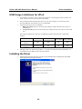
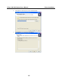
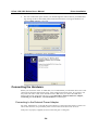
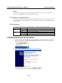
UPort 1400/1600 Series User’s Manual First Edition, June 2006 www.moxa.com/product MOXA Technologies Co., Ltd. Tel: +886-2-8919-1230 Fax: +886-2-8919-1231 Web: www.moxa.com MOXA Technical Support Worldwide: [email protected] UPort 1400/1600 Series User’s Manual The software described in this manual is furnished under a license agreement and may be used only in accordance with the terms of that agreement. Copyright Notice Copyright © 2006 MOXA Technologies Co., Ltd. All rights reserved. Reproduction without permission is prohibited. Trademarks MOXA is a registered trademark of the Moxa Group. All other trademarks or registered marks in this manual belong to their respective manufacturers. Disclaimer Information in this document is subject to change without notice and does not represent a commitment on the part of Moxa. Moxa provides this document “as is,” without warranty of any kind, either expressed or implied, including, but not limited to, its particular purpose. Moxa reserves the right to make improvements and/or changes to this manual, or to the products and/or the programs described in this manual, at any time. Information provided in this manual is intended to be accurate and reliable. However, Moxa assumes no responsibility for its use, or for any infringements on the rights of third parties that may result from its use. This manual might include unintentional technical or typographical errors. Changes are made periodically to the information herein to correct such errors, and these changes are incorporated into new editions of the manual. Table of Contents Chapter 1 Introduction ..................................................................................... 1-1 Overview ...................................................................................................................1-2 Package Checklist......................................................................................................1-2 Product Features ........................................................................................................1-2 Product Specifications ...............................................................................................1-3 Panel Layout..............................................................................................................1-4 Dimensions................................................................................................................1-5 Chapter 2 Driver Installation ............................................................................ 2-1 USB Usage Limitations for UPort.............................................................................2-2 Installing the Driver...................................................................................................2-2 Connecting the Hardware ..........................................................................................2-4 Connecting to the External Power Adaptor .......................................................2-4 Connecting to a Serial Device ...........................................................................2-5 LED Indicators ..................................................................................................2-5 Installing the Driver for the Server............................................................................2-5 Installing the Driver for the Ports ..............................................................................2-8 Configuring the Ports .............................................................................................. 2-11 Uninstalling UPort...................................................................................................2-16 Uninstalling the Driver ............................................................................................2-17 Chapter 3 Pin Assignment ............................................................................... 3-1 Appendix A Service Information.........................................................................A-1 MOXA Internet Services .......................................................................................... A-2 Problem Report Form ............................................................................................... A-3 Product Return Procedure......................................................................................... A-4 1 Chapter 1 Introduction The MOXA UPort 1400/1600 are advanced USB-to-serial hubs that connect to 4, 8, or 16 RS-232 or RS-232/422/485 serial devices. The UPort 1400/1600 Series adds 4, 8, or 16 Windows serial COM ports via its USB connection, and is compatible with new and legacy RS-232 or RS-422/485 devices. This plug and play USB solution is perfect for mobile, instrumentation, and point-of sale applications. In this manual, we refer to the products in the series collectively as UPort 1400/1600 Series. The models in the UPort 1400/1600 Series are: y y y y y y UPort 1410 (4-port RS-232 USB-to-Serial Hub) UPort 1450 (4-port RS-232/422/485 USB-to-Serial Hub) UPort 1610-8 (8-port RS-232 USB-to-Serial Hub) UPort 1650-8 (8-port RS-232/422/485 USB-to-Serial Hub) UPort 1610-16 (16-port RS-232 USB-to-Serial Hub) UPort 1650-16 (16-port RS-232/422/485 USB-to-Serial Hub) The following topics are covered in this chapter: Overview Package Checklist Product Features Product Specifications Panel Layout Dimensions UPort 1400/1600 Series User’s Manual Introduction Overview UPort 1400/1600 Series products are easy to use. Simply install the drivers, connect the UPort to your computer, plug in your serial devices, and you’re ready to go. Programming is NOT required, and you do not need to worry about IRQs, configuring a board, power requirements, or connection schemes. UPort 1400/1600 Series products are compliant with USB 1.0, 1.1, and 2.0 specifications, and meet the 480 Mbps high-speed requirement. Using your computer’s USB ports to connect serial devices reduces the total cost of ownership, investment in hardware, and long term management and integration costs. The UPort 1400/1600 Series supports both bus power and external power via an adapter. Bus power is adapted for laptop or workstation connections that support 500 mA output for USB devices. External power is adapted for those USB hubs that can only produce 100 mA of current. Package Checklist MOXA UPort 1400/1600 products are shipped with the following items: Standard Accessories y y y y y UPort 1400 or 1600 USB-to-Serial Hub 1 USB Cable Document and Software CD-ROM UPort 1400/1600 Quick Installation Guide Power Adaptor (UPort 1400/1600-8) or Power Cord (UPort 1600-16) Optional Accessories y Magnets × 4 (magnets are used to attach the UPort hub to the PC case) NOTE: Notify your sales representative if any of the above items is missing or damaged. Product Features UPort 1400/1600 Series products have the following features: y y y y y y y y y y y y y Hi-speed USB 2.0 supported (up to 480 Mbps) Additional I/O or IRQ not required Serial transmission speed up to 921.6 Kbps 128-byte FIFO and on-chip H/W, S/W flow control Built-in 15 KV ESD protection Windows 2000/XP/2003 drivers supported Both bus power and external power supported Suitable for 4-wire RS-422/485 and 2-wire RS-485 applications Easy maintenance with LED display and management software IP30, rugged metal case COM port assignments maintained across different PCs Optional magnet accessories for attaching on PC case Mini Female DB9 to Terminal Block attachment for easy wiring 1-2 UPort 1400/1600 Series User’s Manual Introduction Product Specifications Models Names UPort 1410/1450, UPort 1610-8/1650-8, UPort 1610-16/1650-16 USB Compliant with USB 2.0, 1.1, 1.0 Connector USB type B Speed High speed 480 Mbps Serial No. of Ports Interface RS-422/485 is for UPort 1450, 1650-8, 1650-16 Connector FIFO Serial line protection 4 (UPort 1410/1450) 8 (UPort 1610-8/1650-8) 16 (UPort 1610-16/1650-16) RS-232: TxD, RxD, RTS, CTS, DTR, DSR, DCD, GND RS-422: TxD+(B), TxD-(A), RxD+(B), RxD-(A), GND 4-wire RS-485: TxD+(B), TxD-(A), RxD+(B), RxD-(A), GND 2-wire RS-485: Data+(B), Data-(A), GND Male DB9 128 bytes 15 KV ESD for all signals Serial Communication Parameters Parity None, Even, Odd, Space, Mark Data bits 5, 6, 7, 8 Stop bit 1, 1.5, 2 Flow Control RTS/CTS, XON/XOFF Speed 50 bps to 921.6 Kbps Power Requirements Power Input Power Consumption Ext. PWR 12 to 48 VDC (External) or 5 VDC (Bus power) UPort 1410: 180 mA (max) UPort 1450: 260 mA (max) UPort 1610-8: 230 mA (max) UPort 1650-8: 580 mA (max) UPort 1610-16: 130 mA (max) UPort 1650-16: 170 mA (max) Mechanical Specifications Material Metal Environmental Operating Temperature Storage Temperature Operating Humidity 0 to 55°C (32 to 131°F) -20 to 75°C (-4 to 167°F) 5 to 95% RH Regulatory Approvals EN55022 Class A, EN55024, EN61000-3-2, EN61000-3-3, EN61000-4-2, EN61000-4-3, EN61000-4-4, EN61000-4-5, EN61000-4-6, FCC Part 15 Class A UL, CUL, TÜV Warranty 5 years 1-3 UPort 1400/1600 Series User’s Manual Introduction Panel Layout UPort 1410/1450 UPort 1610-8/1650-8 UPort 1610-16/1650-16 1-4 UPort 1400/1600 Series User’s Manual Introduction Dimensions UPort 1410/1450 UPort 1610-8/1650-8 1-5 UPort 1400/1600 Series User’s Manual Introduction UPort 1610-16/1650-16 1-6 2 Chapter 2 Driver Installation This chapter includes information about installing the UPort 1400/1600 USB-to-Serial Hub. We present the installation procedure for Windows 2000. The procedures for Windows XP/2003 (32 bit) and Windows XP/2003 (64 bit) are essentially the same as that for Windows 2000. We recommend installing the UPort 1400/1600 driver first, before connecting the UPort 1400/1600 USB-to-Serial Hub to your computer’s USB port. The following topics are covered in this chapter: USB Usage Limitations for UPort Installing the Driver Connecting the Hardware ¾ Connecting to the External Power Adaptor ¾ Connecting to a Serial Device ¾ LED Indicators Installing the Driver for the Server Installing the Driver for the Ports Configuring the Ports Uninstalling UPort Uninstalling the Driver WARNING If your host PC uses an nVIDIA nForce 4 processor and you find that your host PC is not receiving the correct data, you should enter the PC’s BIOS configuration utility and disable USB 2.0. This will cause your host PC to use the USB 1.1 specification, which should prevent the data transmission problem from recurring. UPort 1400/1600 Series User’s Manual Driver Installation USB Usage Limitations for UPort 1. A maximum of 4 UPorts can be connected to each host. Connecting more than 4 UPorts will cause system resources to become low and unstable. 2. We recommend connecting the UPort directly to the host USB port. If you need to use an external USB hub, only the first level is recommended. 3. In general, there are 2 types of USB hub: i. High power hubs require an external power adaptor, and provide 500 mA of power to the USB port. ii. Low power hubs get power from the host PC, and provide 100 mA of power to the USB port. The following table shows what type of USB hub should be used with UPort 1400/1600 products. UPort 1400 UPort 1400 UPort 1600-8 UPort 1600-16 with bus power with external power High power HUB (500 mA) Low power HUB (100 mA) 4. OK OK OK OK Not Supported OK OK OK Although UPort can operate using USB 1.1, to get the best and most stable performance, we recommend using a USB 2.0 host controller or HUB. Installing the Driver 1. Run the Setup program located on the UPort 1400/1600 Document and Software CD-ROM. Click Next to Start installing the driver. 2-2 UPort 1400/1600 Series User’s Manual Driver Installation 2. Click Next to install the driver in the indicated folder. 3. Click Install to proceed with the installation. 2-3 UPort 1400/1600 Series User’s Manual Driver Installation 4. The next window that opens cautions you that although this software has not passed Windows logo testing, the driver has already been tested and shown that it can support Windows OS. Click Continue Anyway to proceed. 5. Click Finish to complete the driver installation. Connecting the Hardware Before you connect the UPort via USB cable, we recommend that you install the driver first. UPort 1400 supports both bus and external power, UPort 1600 needs external power. If you want to use bus power with UPort 1400, switch the DIP switch to bus when you connect the USB cable between the host PC and UPort 1400. We cover Connecting to the External Power Adaptor, Connecting to a Serial Device, and LED Indicators in this chapter. Connecting to the External Power Adaptor For UPort 1600-8 Series, we provide the power adaptor to connect from the host PC to UPort. For UPort 1600-16 Series, we provide the power cord to connect from the host PC to UPort. If the power is properly supplied, the Active LED will glow a solid green. 2-4 UPort 1400/1600 Series User’s Manual Driver Installation Buzzer UPort will sound the buzzer twice when the power is turned on. You will also hear the buzzer when using the Locate function on the driver property page. Connecting to a Serial Device Connect the serial cable between UPort 1400/1600 and the serial device. UPort 1400/1600’s serial ports use the RS-232 or RS-422/485 interface to transmit data. The port uses a standard male DB9 pin assignment. LED Indicators UPort 1400/1600 Series has several LED indicators, as described in the following table. LED Name Active Tx/Rx LED Color Green Off Orange Green Off LED Function Power is on Power is off, or power error condition exists Serial port is receiving data Serial port is transmitting data No data is being transmitted or received through the serial port Installing the Driver for the Server 1. After connecting the USB cable from UPort to host the PC, Windows 2000 will automatically detect the new UPort, and the Found New Hardware balloon will open in the bottom right corner of the Windows desktop. 2. Select No, not at this time. Click Next to start the installation. 2-5 UPort 1400/1600 Series User’s Manual Driver Installation 3. Select Install the software automatically (Recommended), and then click Next to continue. 4. Wait while the installation wizard searches for the correct drivers. The next window that opens cautions you that although this software has not passed Windows logo testing, this driver has already been tested and shown that it can support Windows OS. Click Continue Anyway to proceed. 2-6 UPort 1400/1600 Series User’s Manual Driver Installation 5. Wait while the driver software is installed. 6. The next window shows the model name of the board, and indicates that Windows has completed the driver installation. Click Finish to proceed with the rest of the installation procedure. 2-7 UPort 1400/1600 Series User’s Manual Driver Installation Installing the Driver for the Ports 1. The Found Next Hardware Wizard window will open to help you install the driver for Moxa Port 0. This window will offer to connect to the Windows update site to search for a driver. Select No, not at this time and then click Next to continue. 2. Select Install the software automatically (Recommended), and then click Next to continue. 2-8 UPort 1400/1600 Series User’s Manual Driver Installation 3. Wait while the installation wizard searches for the correct drivers. The next window that opens cautions you that although this software has not passed Windows logo testing, this driver has already been tested and shown that it can support Windows OS. Click Continue Anyway to proceed. 4. Wait while the driver software is installed. 2-9 UPort 1400/1600 Series User’s Manual Driver Installation 5. After all files have been copied to the system, the Completing the Found New Hardware Wizard window will open to indicate that it has finished installing Port 0. Click Finish to proceed with the rest of the installation. 6. Repeat Step 1 through Step 5 for each of the remaining 3 ports (UPort 1400), 7 ports (UPort 1600-8), or 15 ports (UPort 1600-16). The last port to be installed will be MOXA Port 3, 7, or 15, respectively. 7. The Found New Hardware balloon will reappear to inform you that the hardware was installed successfully. 2-10 UPort 1400/1600 Series User’s Manual Driver Installation Configuring the Ports After the driver has been installed, use Device Manager to configure the UPort serial ports. 1. With the System Properties window open, click on the Hardware tab, and then click on Device Manager. 2. Expand the Multi-port serial adapters tab, right click MOXA UPort 1450 Series, and then click Properties to open the UPort’s configuration panel. 2-11 UPort 1400/1600 Series User’s Manual Driver Installation The Ports Configuration page settings are described below. Auto Enumerating COM Number If the “Auto Enumerating COM Number” checkbox is checked, COM numbers will be assigned automatically and in sequence to the ports. E.g., COM3 to Port 1, COM4 to Port 2, etc. If you do not enable this check box, only the first COM Number will be changed to new COM number list in the drop-down list box. Enable this function if you want to configure several ports with sequential numbers. Friendly Name Setting Factory Default Necessity 1 to 20 characters MOXA UPort COM Optional (E.g., UPort 1610-8) Friendly name is specially designed to allow easy identification of the serial devices that are connected to UPort’s serial port. UART FIFO Setting Factory Default Necessity Enable/Disable Enable Required UPort’s serial ports provide a 128-byte FIFO both in the Tx and Rx directions. Disable UART FIFO setting when your serial device does not have a FIFO to prevent data loss during communication. For a slow serial device, we recommend you disable FIFO to improve the latency. If you want to use XON/XOFF flow control, we recommend disabling UART FIFO. 2-12 UPort 1400/1600 Series User’s Manual Driver Installation Tx Mode Setting Factory Default Necessity Hi-Performance, Hi-Performance Required Classical To improve write performance, you can select the Hi-Performance mode. Under classical mode, the driver will not notify the user’s program that Tx is completed until all Tx data has been sent out from the UPort; this mode will cause lower throughput. If you want to ensure that all data is sent out before further processing, classical mode is recommended. Classical mode is the same as the COM Port behavior: The WriteFile() call will only finish when all queued data are sent out. Fast Flush Setting Enable/Disable Factory Default Enable Necessity Required 1. For some applications, the user’s program will use the Win32 PurgeComm() function before it reads or writes data. With our design, after the program uses this PurgeComm() function, the UPort driver will keep querying UPort’s firmware several times to make sure that there is really no data queued in the UPort firmware buffer, rather than just flushing the local buffer. This kind of design is used because of some special considerations. However, it might take more time (about several hundred milliseconds) than a native COM1, because it needs to work via Ethernet. This is why the native COM ports on the motherboard can work fast with this function call, but UPort requires much more time. 2. To begin with, make sure there are some PurgeComm() functions being used in your application program. In this kind of situation, you might find that your UPort exhibits a much poorer operation performance than when using the native COM1 port. Once you have enabled the Fast Flush function, you can check to see if there has been an improvement in performance. 3. By default, the optional Fast Flush function is enabled, the UPort driver will work faster with PurgeComm(). 4. Win32 Function PurgeComm() with PURGE_TXCLEAR will clear all queued Tx data. But for some applications, it will call this function for each transaction and result in low throughput. To avoid this, you can enable this function. The driver will only clear the data queued in the local buffer; it will not send firmware through the USB to clear the data queued in the firmware buffer. Interface UPort 1410, 1610-8, 1610-16 Setting Factory Default RS-232 RS-232 UPort 1450, 1650-8, 1650-16 Setting Factory Default RS-232, RS-422, 4-wire RS-485, 2-wire RS-232 RS-485 2-13 Necessity Required Necessity Required UPort 1400/1600 Series User’s Manual Driver Installation Other Settings Reset default If you click the Rest default button, all the settings will return to Factory default settings: COM Number: Tx Mode: UART FIFO: Fast Flush: Interface: <Assign available COM number automatically> Hi-Performance Enable Enable RS-232 View All Settings: You can preview all ports settings with this function. Advance Settings COM Preserver – Driver Setting Management UPort provides one special function to help you manage the UPort settings. In the general case, you need write down all the settings including COM number to prevent them from being lost. In some applications, to clone multiple systems you also need to worry about how to clone the COM Port settings. Using the UPort COM Preserver function, you just need to save all the settings into UPort device directly– just like a USB Mass Storage device. You do not need to record it using additional paper or disk. If your host crashes, you can just install the driver into new host, plug the original UPort and click the Restore button to restore all settings back very quickly. NOTE If you want to use these settings in another PC, be sure the PC has a free COM port available. Otherwise, the new settings will copy over the settings of a COM port that is already in use. y Save Save all settings to UPort. 2-14 UPort 1400/1600 Series User’s Manual Driver Installation y Restore Read all settings from UPort as new settings. You still need to press the OK button to activate it. y Clear Clear the UPort setting which is stored in UPort Device. This operation is simliar to resettng all the settings to ther factory defaults. The following settings will be saved to UPort if you select Save: COM number, Friendly Name, Transmission Mode, FIFO settings, Fast Flush settings, and Interface. Help Clicking this will open the online help for the product. 2-15 UPort 1400/1600 Series User’s Manual Driver Installation Locate This function can help to identify the UPort location, especially when two or more UPorts are installed. This function will ask the UPort to flash the ready LED and turn on the Buzzer until you stop it. Uninstalling UPort If you want to remove the UPort device, you just need to remove the device from the Device Manager. The UPort driver will still stay alive enabling other UPort devices to keep working. 1. To uninstall the UPort device, click Start Æ Settings Æ Control Panel Æ System, select the Hardware tab, and then click Device Manager. 2-16 UPort 1400/1600 Series User’s Manual Driver Installation 2. Expand the Multi-port serial adapters tab, right click MOXA UPort 1450 Series, and then click Remove to uninstall this UPort device. A window will pop up to confirm if you want to remove this UPort. 3. Click OK to continue uninstalling the UPort device. The UPort device will be removed from the list of Multi-port serial adapters. Uninstalling the Driver 1. To uninstall the driver, open the Control window, and click Add/Remove Programs. 2-17 UPort 1400/1600 Series User’s Manual 2. Driver Installation Select Moxa UPort Windows Driver Ver1.0. Click the Remove button. 2-18 UPort 1400/1600 Series User’s Manual Driver Installation 3. Wait while the driver software is uninstalled. 4. Click OK to proceed with the un-installation procedure. 2-19 3 Chapter 3 Pin Assignment UPort 1410 has 4 RS-232 ports, UPort 1450 has 4 RS-232/422/485 ports, UPort 1610-8/1610-16 has 8/16 RS-232 ports, and UPort 1650-8/1650-16 has 8/16 RS-232/422/485 ports. Serial Port Pinouts DB9 Male RS-232 Port for UPort 1410/1610-8/1610-16 1 6 5 9 Pin 1 2 3 4 5 6 7 8 RS-232 DCD RxD TxD DTR GND DSR RTS CTS DB9 Male RS-232/422/485 Port for UPort 1450/1650-8/1650-16 1 6 5 9 Pin RS-232 1 2 3 4 5 6 7 8 DCD RxD TxD DTR GND DSR RTS CTS RS-422/ 4-wire RS-485 TxD-(A) TxD+(B) RxD+(B) RxD-(A) GND ------- 2-wire RS-485 ----Data+(B) Data-(A) GND ------- A Appendix A Service Information This appendix shows you how to contact Moxa for information about this and other products, and how to report problems. In this appendix, we cover the following topics. MOXA Internet Services Problem Report Form Product Return Procedure UPort 1400/1600 User’s Manual Service Information MOXA Internet Services Customer satisfaction is our primary concern. To ensure that customers receive the full benefit of our products, Moxa Internet Services has been set up to provide technical support, driver updates, product information, and user’s manual updates. The following services are provided E-mail for technical [email protected] World Wide Web (WWW) Site for product information: .............................http://www.moxa.com A-2 UPort 1400/1600 User’s Manual Service Information Problem Report Form MOXA UPort 1400/1600 Customer name: Company: Tel: Fax: Email: Date: 1. 2. Moxa Product: Serial Number: UPort 1410 UPort 1450 UPort 1610-16 UPort 1650-16 UPort 1610-8 UPort 1650-8 _________________ Problem Description: Please describe the symptoms of the problem as clearly as possible, including any error messages you see. A clearly written description of the problem will allow us to reproduce the symptoms, and expedite the repair of your product. A-3 UPort 1400/1600 User’s Manual Service Information Product Return Procedure For product repair, exchange, or refund, the customer must: Provide evidence of original purchase. Obtain a Product Return Agreement (PRA) from the sales representative or dealer. Fill out the Problem Report Form (PRF). Include as much detail as possible for a shorter product repair time. Carefully pack the product in an anti-static package, and send it, pre-paid, to the dealer. The PRA should be visible on the outside of the package, and include a description of the problem, along with the return address and telephone number of a technical contact. A-4