1
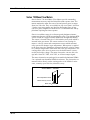
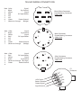
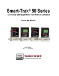
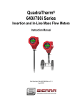
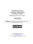
Sierra Series 730 Accu-Mass™
Mass Flow Meters
Instruction Manual
Part Number IM-73-AM
Revision E 05/04
5 Harris Court, Building L Monterey, CA 93940
(831) 373-0200 (800) 866-0200 Fax (831) 373-4402
http://www.sierrainstruments.com
Sierra Instruments b.v. Bolstoen 30A 1046 AV Amsterdam The Netherlands
+31(0)20-6145810 Fax +31(0)20-6145815
Customer Notice
Sierra Instruments, Inc. is not liable for any damage or personal injury, whatsoever,
resulting from the use of Sierra Instruments standard mass flow meters for oxygen
gas. You are responsible for determining if this mass flow meter is appropriate for
your oxygen application. You are responsible for cleaning the mass flow meter to
the degree required for your oxygen flow application.
© COPYRIGHT SIERRA INSTRUMENTS 1994
No part of this publication may be copied or distributed, transmitted, transcribed, stored in
a retrieval system, or translated into any human or computer language, in any form or by
any means, electronic, mechanical, manual, or otherwise, or disclosed to third parties
without the express written permission of Sierra Instruments. The information contained in
this manual is subject to change without notice.
TRADEMARKS
Accu-Mass™ is a trademark of Sierra Instruments, Inc. Other product and company
names listed in this manual are trademarks or trade names of their respective manufacturers.
Revision D: added NEMA 4 enclosure wiring instructions, updated content and format.
Series 730 Instruction Manual
Table of Contents
Series 730 Mass Flow Meters...........................................................3
Safety Information..........................................................................4
Receipt of Components...................................................................4
Technical Assistance.......................................................................4
Installation Overview......................................................................5
Unobstructed Flow Requirements...............................................5
Installation......................................................................................6
Wiring Connections - NEMA 2 Enclosures......................................7
Wiring Connections - NEMA 4 Enclosures......................................7
Output Signal Wiring.......................................................................8
Troubleshooting the Flow Meter......................................................8
Returning Equipment to the Factory..............................................10
Product Specifications...................................................................11
Figures
IM-73-E
1.
Series 730 Sensor Assembly......................................................3
2.
Recommended Pipe Length Requirements................................6
3.
NEMA 2 Wiring Connections..................................................7
4.
NEMA 4 Wiring Connections..................................................7
1
Series 730 Instruction Manual
Warnings and Cautions
Warning! All wiring procedures must be performed with the power Off.
Caution! All flow meter connections and fittings must have the same or higher pressure rating as the main pipeline.
Caution! Do not connect power to the 4-20 mA terminals.
Caution! Before attempting any flow meter repair, verify that the line is de-pressurized.
Caution!
Always remove main power before disassembling any part of the flow meter.
Caution! Printed circuit boards are sensitive to electrostatic discharge. To avoid damaging the board, follow these precautions to minimize the risk of damage:
•
•
•
2
before handling the assembly, discharge your body by touching a grounded,
metal object
handle all cards by their edges unless otherwise required
when possible, use grounded electrostatic discharge wrist straps when handling
sensitive components
IM-73-E
Series 730 Instruction Manual
Series 730 Mass Flow Meters
Sierra’s Series 730 Accu-Mass™ Flow Meters provide outstanding
measurement accuracy and fast 200 millisecond response time. The
meters monitor the mass flow rate of air and process gases in ranges
from 0 to 250 scfm. They are available in pipe sizes from 1/4-inch to
3 inches. Accu-mass meters are ideal for monitoring flows of noncorrosive gases compatible with the device’s wetted materials and applications requiring fast time response.
Sierra’s Accu-Mass sensor is a reference-grade platinum resistance
temperature detector (RTD) encapsulated in glass. The platinum RTD
wire is wound on a rugged ceramic mandrel for strength and stability.
The sensor is located at the tip of a 304 stainless steel probe which is
inserted in the gas stream. The sensor consists of two sensing elements–a velocity sensor and a temperature sensor which automatically corrects for changes in gas temperature. When power is applied
to the flow meter, the transducer electronics heats the velocity sensor
to a constant temperature differential above the gas temperature. The
cooling effect of the air as it passes over the heated sensor is measured by the bridge voltage. The meter electronics converts this voltage into a linear 0-5 VDC, 0-10 VDC, or 4-20 mA output signal.
The meter electronics are packaged in an anodized aluminum NEMA
2 or a painted cast aluminum NEMA 4 enclosure. The electronics are
mounted either directly on the sensing probe or for NEMA 2 enclosures, remotely up to 100 feet (60 meters) away.
Accu-Mass™ Sensor
Heat
Gas temperature sensor
Heated velocity sensor
Mass flow
Figure 1. Series 730 Accu-Mass Sensor Probe
IM-73-E
3
Series 730 Instruction Manual
Safety Information
We use caution and warning statements in this book to draw your attention to important information.
Warning!
This statement appears with information that is
important to protect people and equipment from
damage. Pay very close attention to all warnings that apply to your application.
Caution!
This statement appears with information that
is important for protecting your equipment
and performance. Read and follow all cautions that apply to your application.
Receipt of Components
When receiving a Sierra mass flow meter, carefully check the outside
packing carton for damage incurred in shipment. If the carton is damaged, notify the local carrier and submit a report to the factory or distributor. Remove the packing slip and check that all ordered components are present. Make sure any spare parts or accessories are not
discarded with the packing material. Do not return any equipment to
the factory without first contacting Sierra Customer Service.
Technical Assistance
If you encounter a problem with the flow meter, review the configuration information for each step of the installation procedure. Verify
that the flow conditions are consistent with factory recommendations. Refer to Troubleshooting for specific information and recommendations.
If the problem persists after following the troubleshooting procedures
outlined in this manual, contact Sierra Instruments by fax or by Email ([email protected]); or, visit the Sierra website at
www.sierrainstruments.com for further assistance. For phone support
you may call (800) 866-0200 or (831) 373-0200 between 8:00 a.m.
and 5:00 p.m. PST. In Europe contact Sierra Instruments b.v. at +31
20 6145810. When contacting Technical Support, make sure to include this information:
•
•
•
4
the flow range, serial number, Sierra order number and model
number (all marked on the meter nameplate)
the problem you are encountering and any corrective action taken
application information (gas, pressure, temperature and piping
configuration)
IM-73-E
Series 730 Instruction Manual
Installation Overview
When selecting an installation site, make sure that:
1. Line pressure and temperature will not exceed the flow meter
rating. Temperature should not vary more than 120°F (50°C)
from the calibration temperature. Line pressure should not
vary more than 50 psi (3.4 bar) around the calibrated pressure.
2. The ambient temperature falls within the limits of: 32°F (0°C)
to 120°F (50°C).
3. The location meets the required minimum number of pipe diameters upstream and downstream of the sensor head (see Figure 2).
4. Safe and convenient access with adequate clearance. Also,
verify the meter is located where the gas is clean and dry and
the meter is calibrated for the gas to be measured.
5. For remote installations, verify the supplied cable length is
sufficient to connect the flow meter sensor to the remote
electronics. (Do not extend or shorten the supplied cable between the probe and the electronics.)
Also, before installation check your flow system for anomalies such as:
• leaks
• valves or restrictions in the flow path that could create disturbances in the flow profile that might cause unexpected flow rate
indications
• heaters that might cause rapid excursions in the measured temperature
Unobstructed Flow Requirements
Select an installation site that will minimize possible distortion in the
flow profile. Valves, elbows, control valves and other piping components may cause flow disturbances. In order to achieve accurate and
repeatable performance install the flow meter using the recommended
number of straight run pipe diameters upstream and downstream of
the sensor given in Figure 2.
IM-73-E
5
Series 730 Instruction Manual
10 D
Flow
5D
Flow meter
10 D
Flow
5D
Flow meter
Reduction before meter
One 90° elbow before meter
15 D
5D
20 D
Flow
Flow
Two 90° elbows before
meter in one plane
25 D
Flow meter
Expansion before meter
10 D
25 D
Flow
5D
Flow meter
10 D
Flow meter
Flow
Two 90° elbows before meter out
of plane (if three 90° bends present,
double recommended length)
Flow meter
Regulator or valve partially closed before meter
(If valve is always wide open, base length
requirements on fitting directly preceding it)
D = number of diameters of straight pipe required between the disturbance and
the flow meter (upstream); and, number of diameters of straight pipe required
downstream of the flow meter
Figure 2. Recommended Pipe Length Requirements for Installation
Installation
The following instructions are general in nature and intended for
guideline purposes only.
Caution!
All flow meter connections
and fittings must have the
same or higher pressure
rating as the main pipeline.
1. Turn off the flow of process gas. Verify that the line is not
pressurized.
2. Confirm that the installation site meets the minimum upstream
and downstream piping requirements.
3. Position the meter with the flow direction arrow pointing downstream in the direction of flow.
4. Tighten fittings until leak tight (refer to published standards for
specific recommendation).
5. Check the system’s entire flow path thoroughly for leaks.
6
IM-73-E
Series 730 Instruction Manual
Wiring Connections - NEMA 2 CE Enclosures
Warning!
All wiring procedures
must be performed
with the power Off.
NEMA 2 enclosures are supplied with a 6-pin connector for direct
connection to the supplied mating connector. The pin designations
are given in Figure 3 below. Connect 15 VDC input power (300 mA
load, maximum) to pin 1 and power ground to pin 5. See “Output Signal Wiring” for signal wiring instructions.
•Female Cable Socket Mating Connector (Female Solder Side View)
5
1
6
2
4
3
1 Positive power lead (Red)
2 Output signal (Wht)
3 Signal common (Blk)
4 Bridge voltage (Org Not Required)
5 Power return (Grn)
6 Shield (Not Required)
Figure 3. NEMA 2 CE Enclosure Wiring Connections
IM-73-D
7
Series 730 Instruction Manual
Output Signal Wiring
All flow meters are equipped with either a calibrated 0–5 VDC, 0–10
VDC or 4–20 mA output signal. These linear output signals represent
0 to 100% of the flow meter user full scale.
DC Output Wiring
The 0-5 VDC or 0-10 VDC output signal can drive a minimum load of
1000 Ohms. For 0-5 VDC or 0-10 VDC connections, connect to the
terminals marked Output signal and Signal ground.
Caution!
Do not connect power to
the 4-20 mA terminals.
4–20 mA Output Wiring
The 4-20 mA current loop output is self-powered (non-isolated).
The maximum loop resistance (load) for the output is 400 Ohms. For
a 4–20 mA connection, connect to the terminals marked Output signal and Signal ground.
Troubleshooting the Flow Meter
Begin hardware troubleshooting by verifying the following facilities issues are correct. These areas impact system operation and must be
corrected prior to performing any flow meter inspections.
Caution!
Before attempting any flow
meter repair, verify that the
line is not pressurized.
Caution!
Always remove main power
before disassembling any
part of the mass flow meter.
1. Verify the incoming power to the flow meter is present and of the
correct voltage and polarity.
2. Check the flow meter wiring for correct connections.
3. Verify the flow meter is installed with the correct number of upstream and downstream pipe diameters as shown in Figure 2.
4. Verify the flow direction indicator is correctly aligned pointing
downstream of flow.
5. Make sure there are no leaks in the line being measured.
After verifying the factors above, follow the troubleshooting procedures
outlined on the next page. If you need to return the flow meter to the
factory, see page 10 for return shipping instructions.
Flow Meter Calibration
Sierra Instruments maintains a fully-equipped calibration laboratory.
All measuring and test equipment used in the calibration of Sierra meters are traceable to NIST standards. Sierra is ISO-9001 registered and
conforms to the requirements of ANSI/NCSL-Z540 and ISO/IEC
Guide 25. If the flow body or electronics have been damaged or you
simply want to have the flow meter re-calibrated, contact the factory
for return shipping instructions. Calibration must be performed by
qualified personnel using NIST-traceable equipment.
8
IM-73-E
Series 730 Instruction Manual
Problem
Possible Cause
Solution
Flow measurement is
erratic or fluctuating
Very erratic or non-uniform flow
Follow installation requirements
shown in Figure 2
Flow meter installed with less than required minimum pipe diameters upstream and downstream of the sensor
Follow installation requirements
shown in Figure 2
Probe is not secured to a solid base
Secure probe to a non-vibrating solid
mount
Sensor component broken
Return to factory for replacement
Malfunction in system
electronics
Return to factory for evaluation
Moisture present in gas flow
Install a water trap or filter upstream
of the flow sensor
Velocity measurement
seems too high or low
Sensor assembly not aligned correctly
to flow
Correct alignment with the flow indicator pointing downstream in the direction of flow
No response to flow from
sensor assembly
No power
Turn on power to the flow meter
Flow profile distortions
Try to find another location for the
meter
Extremely turbulent flow
Do not place the meter near a ventilator, static mixer or valve
Sensor failure
Return to factory for repair
Malfunction in system
electronics
Return to factory for evaluation
Out of calibration
Return to factory for calibration
Probe tip is broken
Return to factory for repair
4-20 mA output circuit not
indicating 4 mA at zero
flow
Improper current loop resistance; total
current loop resistance must be no
less than 150 Ohms and no greater
than 450 Ohms
Install load resistor or use larger
gauge wire
Output pegs plus or minus
Flow body not plugged in
Plug in both connectors
Malfunction in system
electronics
Return to factory for evaluation
System will not zero
IM-73-E
9
Series 730 Instruction Manual
Returning Equipment to Factory
Before returning any mass flow meter to the factory, you must complete a Sierra Calibration/Repair Data Sheet. You may download the
data sheet to your computer by visiting the Sierra website at
www.sierrainstruments.com. Or, contact Customer Service at:
[email protected] (Email) or,
(800) 866-0200 or (831) 373-0200 in the US,
or +31(0)20-6145810 in Europe.
Return shipments to:
USA Headquarters
Sierra Instruments Service Department
5 Harris Court, Building W
Monterey, CA 93940
European Headquarters
Sierra Instruments b.v. Service Department
Bolstoen 30A
1046 AV Amsterdam, The Netherlands
When returning a component, make sure to include the completed
Calibration/Repair Data Sheet with the shipment.
10
IM-73-E
Series 730 Instruction Manual
Product Specifications
Operating Specifications
Gases
Most non-combustible, non-corrosive gases
Mass Flow Rates
NPT Size
1/4-inch
1/2-inch
3/4-inch
1 1/4-inch
2-inch
3-inch
Mass Flow Rate for Air(1)
Minimum Range
0–0.035 scfm
0–0.5 scfm
0–1 scfm
0–2 scfm
0–5 scfm
0–10 scfm
Maximum Range
0–4.5 scfm
0–12 scfm
0–25 scfm
0–50 scfm
0–125 scfm
0–250 scfm
(1) Contact factory for ranges of other gases
Gas Pressure
150 psig (10 barg)*
*Maximum gas pressure is determined by the mechanical process connections, as well as, the application conditions. Mechanical limitations are shown above, please consult factory for application
limitations.
Pressure Drop
Negligible
Gas & Ambient Temperature Gas.............................14° to 176°F (–10° to 80°C)
Ambient......................32° to 120°F (0° to 50°C)
Leak Integrity
1 X 10⁻² atm cc/sec of helium maximum
Power Requirements
15 or 24 VDC, 300 mA
Output Signal
Linear 0-5 VDC or 0-10 VDC proportional to mass flow rate, 1000 Ohms
minimum load resistance; or, linear 4-20 mA proportional to mass flow rate,
400 Ohms maximum resistance
Performance Specifications
Accuracy
± 1% of full scale + 0.5% of reading over 32 to 120°F (0 to 50°C) and 5 to 30
psia (0.3 to 2 barg)
Repeatability
± 0.2% of full scale
Temperature Coefficient
± 0.02% of reading per °F within ± 50°F of customer specified conditions
± 0.03% of reading per °F within ± 50°F to 100°F of customer specified conditions
±0.04% of reading per °C within ± 25°C of customer specified conditions
±0.06% of reading per °C within ± 25°C to 50°C of customer specified conditions
Pressure Coefficient
Negligible within ±50 psig (3.4 barg) of customer specified conditions
(Special calibration required for higher pressures)
Response Time
200 milliseconds to 63% of final velocity value
Physical Specifications
IM-73-E
Wetted Materials
Anodized aluminum or 316 stainless steel flow body
Glass-coated sensor; epoxy; Viton O-rings
Enclosure
Anodized aluminum NEMA 2
Painted cast aluminum NEMA 4
11
730/600 WIRING CONNECTIONS
No#.
1
2
3
4
5
6
7
Color
Signal
Black
Sig. Ground
White
Signal
Red
DC input Power
N/C
N/C
Green
Power Ground
(Brown or Orange)
(Bridge)
No#.
1
2
3
4
5
6
7
Color
Signal
Black
Sig. Ground
White
Signal
Red
DC input Power
N/C
N/C
Green
Power Ground
(Brown or Orange)
(Bridge)
No#.
1
2
3
4
5
6
Color
Signal
Red
DC input Power
White
Signal
Black
Sig. Ground
(Brown or Orange) ( B r i d g e )
Green
Power Ground
1
Blue Hi Rose Connector
Female Mating Connector
Solder Side
6
2
5
7
4
3
7
1
6
2
Black Connector
Female Mating Connector
Solder Side
5
3
4
3
4
2
6
5
Silver Connector
Female Mating Connector
Solder Side
1
E7
Enclosure
+VDC Input
Power Ground
Output Signal
Signal Ground
Red
en
Gre
ite
Wh
ck
Bla
N/C
To Sensor