1
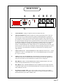
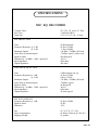
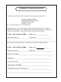
MANLEY
LABORATORIES, INC.
OWNER'S MANUAL
MIC EQ 500 COMBO
MANLEY LABORATORIES, INC.
13880 MAGNOLIA AVE.
CHINO, CA. 91710
TEL: (909) 627-4256
FAX: (909) 628-2482
email: [email protected]
http://www.manleylabs.com
CONTENTS
SECTION
PAGE
INTRODUCTION
3
MAINS CONNECTIONS
4
CONNECTING YOUR PREAMPLIFIER
5
CONNECTION EXAMPLES
6
HINTS
7
EQ CURVES
8
BASIC MAINTENANCE
9
FIGURE 1
FRONT PANEL
11
FIGURE 2
REAR PANEL
12
OPERATIONAL NOTES
13
SPECIFICATIONS
14
WARRANTY
15
WARRANTY REGISTRATION
16
TEMPLATE TO RECORD SETTINGS
FREE
page 2
INTRODUCTION
THANK YOU!...
for choosing the Manley Laboratories "MIC EQ 500 COMBO". Designed by David Manley, The
MIC EQ 500 COMBO uses the best available parts with the, cleanest, signal path possible. This preamp
features a new fully differential Mic preamplifier with transformer coupled input and output. This circuit
is similar to the Manley Variable Mu Limiter/Compressor and is considered the finest line amplifier
currently being built. 48 volt Phantom power is available and switched from the front panel. The switch
is a safety type that must be pulled to toggle. Gain is variable from zero to +55 dB (46+9). There is also
a line stage with EQ and variable gain. Like our Pultecs, we chose to model this EQ after an existing
vintage design. This EQ is highly praised by Mastering engineers and collectors of the best audio gear.
The original passive EQ was designed by Arthur Davis who seems to have worked for Altec Lansing,
Cinema Products, Universal Recording and Langevin... always taking his seminal design along with him.
The complexity of the switching (using Greyhill custom build gold contact switches in our reincarnation)
is solely for the purpose of having no more than 3 components in the signal path (1R, 1L, 1C) at any
given moment for maximum signal purity. True, there are many equalizers around with more doo-dat
knobs but they sacrifice a great deal of musicality for the sake of "more buttons". The feature we hold as
singularly important is "sonic beauty" because without this an equalizer with 128 knobs is not worth
using. Passive equalizers do not boost the signal. There is an insertion loss of about 10 dB in the passive
EQ. To return the signal to "unity gain" and simulate boosts we have added our differential amplifier
which then allows variable gain.
The input / output structure of the MIC EQ-500 COMBO allows unusual flexability. One can
"insert" compressors and gates before or after the EQ, One can use the MIC PRE for "direct to tape"
recording and use the variable gain and EQ for monitoring. If the user desires, the unit can be pushed to
distort by turning up the MIC GAIN and turning down the LINE GAIN. The built in VU meter is useful
for any of these purposes.
Thank you again, and please enjoy!
GENERAL NOTES
LOCATION & VENTILATION
The Purist Preamplifier must be installed in a stable location with ample ventilation. It is recommended,
if this unit is rack mounted, that you allow enough clearance on the top and bottom of the preamp such
that a constant flow of air can flow through the ventilation slots. We also recommend that the unit not be
'sealed up" in a 2U road case as these will not provide the neccessary ventilation.
WATER & MOISTURE
As with any electrical equipment, this preamplifier should not be used near water or moisture.
SERVICING
The user should not attempt to service the preamplifier beyond that described in the owner's manual.
Refer all servicing other than tube replacement to Manley Laboratories.
SPECIAL NOTES
Tubes may become loose during transit. Straighten and press down each tube before plugging the unit
into the mains socket. Furthermore, do not touch the tubes after the unit has been switched on, as the
tubes do become very hot during operation. Be aware that high voltages exist in this unit and that at least
15 minutes should be allowed for capacitors to discharge after power is turned off.
page 3
MAINS CONNECTIONS
Your MIC EQ-500 COMBO has been factory set to the correct mains voltage for your country.
The voltage setting is marked on the serial badge, located on the rear panel. Check that this
complies with your local supply.
Export units for certain markets have a moulded mains plug fitted to comply with local requirements. If your unit does not have a plug fitted the coloured wires should be connected to the
appropriate plug terminals in accordance with the following code.
GREEN/YELLOW
BLUE
BROWN
EARTH
NEUTRAL
LIVE
terminal
terminal
terminal
As the colours of the wires in the mains lead may not correspond with the coloured marking
identifying the terminals in your plug proceed as follows;
The wire which is coloured GREEN/YELLOW must be connected to the terminal in the plug
which is marked by the letter E or by the safety earth symbol or coloured GREEN or GREEN
and YELLOW.
The wire which is coloured BLUE must be connected to the terminal in the plug which is
marked by the letter N or coloured BLACK.
The wire which is coloured BROWN must be connected to the terminal in the plug which is
marked by the letter L or coloured RED.
DO NOT CONNECT/SWITCH ON THE MAINS SUPPLY UNTIL ALL OTHER CONNECTIONS HAVE BEEN MADE.
CONNECTING YOUR PREAMPLIFIER
Setting up your Mic EQ-500 COMBO is rather easy.
1. Please refer to page 12 for an illustration of the back of the preamplifier. The following
page shows some slightly more involved examples. On the left end of the back panel is
a standard IEC mains connector. This should be connected to a standard mains outlet
with the supplied cable. This unit has been hard-wired for the mains voltage in your
country
2. There are two main XLR male outputs. The MIC PRE OUT can be used to send the
amplified mic signal direct to tape (without EQ) or to feed compressors and gates. The
LINE OUT is normally the output to the tape machine The pin out for the XLR is as
follows:
PIN1 - ground
PIN2 - POSITIVE going phase (+)
PIN3 - NEGATIVE going phase (-).
3. There are two XLR female inputs. The first is the MIC INPUT. Connect the mic to this.
The second is a LINE INPUT. To use the EQ in a mix use the console INSERTs to feed
a line level signal into the LINE INPUT and return it from the LINE OUTPUT. The
LINE INPUT can also be used to insert a compressor and gate into the signal chain.
4. Power up the MIC EQ-500 COMBO with the gain controls initially set off or low and
with the EQ bypassed.
5. If a dynamic or ribbon mic, tube condensor mic or passive DI is used then PHANTOM
should be OFF. If a solid state (FET) condensor mic is used then the PHANTOM
switch may have to be turned on. This switch must be gently pulled before toggling.
This is a safety switch meant to protect your speakers, recordings, mics and input
transformer. If the 48 volt phantom power is fed into a unbalanced line or shorted mic
cable then you risk damaging the input transformer. Manley Labs uses the technique of
feeding the 48 volts into the center tap of the bifilar wound input transformer. While
this may occasionally damage the transformer or current limiting resistor in a mis-wired
situation, it allows certain mics to truly reach their potential sound-wise.
6. Select MIC or LINE on the toggle switch depending on the set-up, turn up the LINE
GAIN to 12:00 and slowly turn up the MIC GAIN until the meter reads just under the
red area or 0 VU.
7. If EQ is desired, switch from BYPASS to EQ IN and adjust the dB and FREQUENCY
and SHELF as needed.
8. Final adjustment of levels should be trimmed while looking at the tape recorders meters
or console meters and by ear. While the VU meter on the unit is of good quality and
calibrated, digital recording goes hand in hand with PEAK meters. VU meters while
standard for analog recording are not a guarantee that the recording will be clean.
Percussive sounds with lots of highs are very good candidates for a lower recording
level.
The following page has diagrams of typical set-ups.
THIS PAGE FOR CONNECTION EXAMPLES
page 6
HINTS, notes, etc
The MIC EQ-500 COMBO preamp section and make-up gain stage use a similar circuit to
several of our most expensive yet most popular circuits. The MANLEY VARIABLE MU
LIMITER COMPRESSOR uses a similar topology. It would be described as a transformer input,
fully differential tube amplifier, transformer output.
The "optimum" setting of the MIC GAIN control is simple - Describing technically what to
do is difficult. If a microphone is plugged in to the MIC IN and the MIC PRE OUTPUT is
connected to a digital tape recorder then look at the recorder's meters to set the level. If the LINE
OUTPUT is used because EQ is wanted then still use the digital recorder's meters. Then why
include a VU meter ? The key phrase is "digital (tape) recorder". They use peak meters rather than
VU meters and the readings will probably be different. VU meters are the standard for "analog"
tape machines and many consoles. You can still use the internal VU meter to get an optimum
setting for the MIC GAIN. You should have the EQ INPUT set to MIC PRE OP, the EQ in
BYPASS and the LINE GAIN around "12:00" or straight up. Set the MIC GAIN so that the needle
rarely gets into the "red". Once you add a bit of EQ then you may want to adjust the LINE GAIN
by watching the internal meter or by watching the tape machine or console meters.
You can "insert" your favorite compressor and gate two ways. The first way is to go from
the MIC PRE OUTPUT to the compressor's input and then from the compressor's output to the
LINE IN. Switch to LINE IN to "hear" the compressor or switch to MIC PRE OP to bypass the
compressor. The second way is to patch the compressor between the LINE OP and the tape
machine. The first way the compressor is before the EQ and the second way puts the compressor
after the EQ.
The EQ is a passive circuit meaning that the entire EQ uses only inductors, capacitors and
resistors to give cut and boost at various frequencies. These types of circuits often have a tendency
to sound better than op-amp based circuits. This seems to be yet another proof that less is more
when it comes to recording.
This EQ uses stepped CUT & BOOST controls. This is pretty rare in studios but very
common in mastering. Mastering engineers prefer stepped controls because it allows returning to
exact settings and quality stepped controls are known to sound better than pots. Stepped
FREQUENCY controls are pretty much the only choice in a passive EQ's. The EQ frequency is
determined by switching in different capacitors and inductors. There is no bandwith or " Q"
control but the PEAK / SHELF switch is a close cousin in this unit. The SHELF mode is a lower
Q or wider bandwidth than PEAK. In boost modes the SHELF setting is actually part PEAK and
part SHELF. Take a look at the curves on the next page. In CUT settings the SHELF mode is a
true shelf. The other thing to notice is that in SHELF the actual cut and boost is less than the in
PEAK mode. The numbers marked around the EQ knobs are pretty accurate in PEAK but not in
SHELF. To the ear the difference between PEAK and SHELF may be subtle. This is especially
true at 40 Hz and 15 Khz because the differences are so close to the edge of the spectrum. The
3Khz and 5Khz show the differences most clearly.
The LINE IN input impedance is 1000 ohms which may be difficult for some semi-pro IC
gear. The symtom would be distortion at high levels. Vintage gear is typically 600 ohms - tougher.
page 7
This page is reserved for freq resp curves
Try taking advantage of the separate MIC and LINE sections by feeding to tape with the MIC
PRE OUTPUT and returning the signal from tape to the LINE INPUT. Send the LINE OUTPUT to a
good little mixer (no EQ) or directly to your power amp. Now you can use the LINE GAIN control
as a mix / monitor level and maybe use the unit's EQ while recording "flat". If you had two (or
more), this would be the "Purist" live to 2 track approach.
Another advantage of separate MIC and LINE GAINS is for true tube distortion. This unit
can be made to distort. Turn up the MIC GAIN and turn down the LINE GAIN. The depth of the
distortion depends largely on how "hot" the mic signal started out. If you feed a line level signal into
the MIC IN then - no problem distorting but the controls will be very "sensitive". Inserting a tube
compressor between the MIC OUTPUT and LINE INPUT may help particularly if it can be turned
up as well. For more extreme effects use a guitar processor / preamp in the loop. Also, if the
distortion gets buzzy or raspy the EQ section will help. Roll off some highs - Try -10 dB at 10K or
15K. Sometimes boosting 100 or 40 works. Approach the EQ as if you are trying to simulate a 12"
speaker......The distortion typically produced could easily be described as warm and rich. In some
ways it sounds like analog tape distortion. Probably the iron in the transformers....
Now that we have described how to distort audio reality, the real outstanding feature of this
unit is its clean and clear reproduction from a microphone. The first function of The EQ-500 is to
provide a very pristene Mic - Pre and EQ. It is audibly and measurably cleaner, quieter and smoother
than our other mic pre-amps. It will probably set the standard for high end mic pre's - tube or solid
state. Part of the key is the transformers. We wind our own. Transformers are part of the "magic" of
highly desirable gear like NEVE and FOCUSRITE modules. Even though these pieces are solid
state, they are generally regarded as warm and natural. The MIC EQ 500 has an added avantage in
that it is vacuum tube based and has less negative feedback than virtually all solid state preamps.
This has a very positive effect on transients. All this and harmonic accuracy too.
There are other hints in using a mic pre of this quality. These hints fall under the catagory of
mic choice and positioning. Most important is the player and the instrument. Choice of gear is
negligable compared to choice of musician. OK, so now you have great sound in the room, now you
pick a mic, get it close and record. This is the quick way and sometimes the best way for busy
people. Choice of mic is super-important. Using a cheap mic with a great mic pre like this is only a
little better than using the console mic pre. Using a great mic will be the difference of magic from
tragic. "Manley make this big gold mic that you gotta try...". Mic placement is another very effective
tool and damn cheap for the amount of tone change you get. If in doubt try moving the mic before
moving the knob. Try listening in the room in various locations rather than going with what you
thought you saw on MTV. Even if it worked before, this is a new song, possibly a different
musician, probably a different room location. Try moving the mic - It helps to relieve boredom on
those long sessions and often it makes life much easier when it comes to mixing. When in doubt just make it real natural-like. Almost always the musician will appreciate it. You can always twist up
the sound in the mix. Fix it in the mix - yeah right - This is why you bought an expensive mic pre.
Enjoy - Have a good session.
page 9
BASIC MAINTENANCE
CHANGING THE FUSE
As with most gear a fuse may need to be replaced. The symptom is "no power" and no LEDs lit even though
you have checked that it is plugged in correctly. The first thing to check is the fuse. Unplug the AC power before taking
a look at the fuse - Simply turning the EQ 500 "off" is not safe enough. A blown fuse will either look "blackened" or the
little wire inside will look broken. If you have a multi-meter you can check continuity of the fuse. A good fuse will look
very similar to the reading you get simply by shorting the test leads. Remember that the fuse is there to protect the unit
from big damage caused by small problems. Replacing the fuse with the wrong value could be disasterous and would
void the warranty. Use a 2 Amp Slo-Blo type or "MDL 2". If this fuse blows then there is very likely a problem that
requires a technician or return to Manley Labs for repairs.
CHANGING THE METER LAMP
The lamp behind the meter should last several years but it is incandescent and will eventually burn out. The
symtom is that everything works but the meter is dark. To replace the lamp is very easy. Unplug the power and let the
unit rest for at least 15 minutes to allow the capacitors to drain. You could get a shock if you poke around inside the unit
too soon after powering down. Remove the two phillips screws holding the top perforated panel in place. They are
located at the top of back panel. Slide the perforated top back at least half way. Behind the meter you will see a small
black printed circuit board with what looks like a fuse. This is the lamp. Replace it with the same type which is a 12 volt.
0.15 amp (150 mA) and the size is 1/4" X 1 1/4". If you have difficulty finding such a lamp - call us and we will mail
one to you for a small charge.
CHANGING A TUBE
Like lamps, tubes have a lifespan. Sometimes this is a few years and sometimes it is a few decades. 30 years
ago the average person could repair his TV or radio by removing the tubes and taking them down to the local drug store
where a tube tester was available. They could buy the tubes there and have an entertained family in less than an hour.
Almost as easy as changing a light bulb. Changing the tubes in this unit is easy and should not require a technician if you
can get the tubes (you can get them from us). The symtoms can be; loss of signal in one section, microphonics (tapping
on the unit causes too much noise in the speakers), hiss has increased or unusual distortion has become apparent. Follow
the instructions for changing the Meter Lamp to open the top of the unit. The two tubes involved with the MIC PRE are
located toward the side of the unit. The other two tubes are involved with the LINE AMP and EQ. A tube that has turned
white is a sign that air has leaked into the vacuum (as opposed to the vacuum leaking out). A tube that does not have a
slight glow when powered is a sign that it it is not functional. If you have waited at least 15 minutes - the tubes should be
cool. Gently wiggle out the tubes to pull them out. You do not want to damage the printed circuit board. Replace one or
all. Put the cover back on and test out the audio.
ADJUSTING THE METER GAIN
This unit has been factory aligned but should you need to re-adjust, follow these instructions. There is a trim pot
located in the unit mounted on a small printed circuit board mounted right on the LINE OUT XLR. You will need a
good "reference meter" to calibrate to. Plug it into the LINE OUT XLR. Put a 1Khz oscillator tone into the LINE IN.
Adjust the LINE GAIN for 0 VU (+4 dBm) (1.23 VAC) on the reference meter. Do not touch anything except the trim
pot and do not put pressure on the trim pot because the leads could break. Adjust the trim pot for 0 VU on the internal
meter. Done. Close it back up.
LAMP
TUBE LOCATIONS
MIC
PRE
BLOCK DIAGRAM OF MIC EQ-500 COMBO
5751
MIC
IN
MIC
GAIN
TUBE
MIC
PREAMP
MIC
PRE
OUT
LINE AMP
7044
5751
6414
MIC
PASSIVE
EQ
TUBE
LINE
AMP
LINE
GAIN
LINE
OUT
LINE
IN
METER TRIM
page 10
FRONT PANEL
A
MANLEY
FULLY DIFFERENTIAL
PHASE
0º
180º
ALL TUBE
B
PHANTOM
48V ON
PULL
C
EQ INPUT
D
E
MIC INPUT
LINE GAIN
MIC PRE OP
LINE IN
LEVEL
MIC / EQ 500 COMBO
EQ
100 HZ
SHELF
DESIGNED BY DAVID MANLEY
2
-0+
4
4
6
HANDCRAFTED IN CHINO, CALIFORNIA
BYPASS
F
40 HZ
G
PEAK
H
6
8
8
10
I
dB
LEVEL
2
2
10
L
F
H
F
-0+
4
35
2
4
6
71015
SHELF
6
8
8
10
dB
J
10
POWER
PEAK
KHz
K
L
M
A PHASE - Changes the polarity of the Mic signal from 0º to 180º In 0º a positive going signal at the input
produces a positive going signal at the output. Be aware that many mics were built before the XLR
standards were agreed upon (PIN 2 = HOT). The effect of this switch is apparent when two mics are
used on one instrument. In general the setting with the most lows is probably "in phase". One example
is with one mic above a snare drum and another mic below. When combined the result will usully be a
loss of bass because one mic is hearing the skin going toward the mic while the other hears the skin
going away. "Flipping" the polarity of one of the mics usually solves the problem. Anytime leakage is
obvious then phase should be a concern. Distance is one factor that makes selecting the phase more of
a decision than a science. Certain instruments sound more natural when the phase of even a single mic
is right. Vocalists will hear the headphones better if the phase is correct too.
B PHANTOM - When ON puts 48 volts onto the MIC INPUT XLR. Leave it OFF for dynamic or ribbon
mics, tube condensor mics or passive DI's and ON for most solid state (FET) condensor mics. You
must gently PULL the switch to toggle. This is a safety feature to prevent damage to speakers,
recordings, the mic or the input transformer. A shorted mic cable or unbalanced input combined with
PHANTOM could also cause damage. The LED indicates PHANTOM POWER.
C EQ INPUT - Selects either the MIC PRE OUTPUT or LINE INPUT to feed the EQ SECTION. If a
Compressor (etc) is patched between MIC PRE OUTPUT and LINE INPUT then this switch acts as a
"INSERT" switch.
D MIC GAIN Controls the amount of microphone pre-amp gain from Off to +45 dB. More gain if needed is
available with the LINE GAIN control.
E LINE GAIN - Controls the Output Level (before the meter).
F EQ / BYPASS - When this switch is up the EQ section and amplifier are in circuit. BYPASS mode is a
"hardwire" bypass connecting LINE INPUT directly to LINE OUTPUT.
G 100 HZ / 40 HZ - Switches the LOW FREQUENCY EQ "center" frequency.
H LF SHELF / PEAK - Switches the LOW FREQUENCY EQ to a "modified" shelf and lowers the Q when
up. Shelf mode affects frequencies below the center frequency which means if "40 HZ" is selected
little difference will be heard. See the typical EQ curves on page 7 and the explanation on page 6.
I LOW FREQUENCY EQ - Cut and Boost at 40 or 100 HZ in 2 dB steps. A quality Grayhill gold contact
switch is used rather than a pot. At "0" position this section is truly bypassed. In SHELF mode the
steps are smaller and the maximum cut is 7 dB and boost is 6 dB.
J HIGH FREQUENCY EQ - Similar to above except highs are boost and cut.
K HF SHELF / PEAK - Similar to above except highs are affected. See the curves.
L HIGH FREQUENCY SELECT - Choice of 3kHz, 5 kHz, 7 kHz, 10 kHz and 15 kHz.
M VU METER - Reads the signal from the LINE OUT XLR. 0 VU = +4dBm.
N POWER SWITCH - This switch should be up and both the LED and meter will illuminate - Sound will
follow in about 10 seconds. Let it warm up 15 minutes for best results. Do not flip the power on and
off rapidly as this could damage the bridge rectifiers in the power supply.
REAR PANEL
A
REPLACE WITH
SAME TYPE
AND RATING
B
FUSE
2 AMP
SLO-BLO
C
D E
F
LINE OUT
LINE IN
MIC PRE IN
CIRCUIT
GROUND
CHASSIS
WARNING
TO REDUCE THE RISK OF FIRE OR SHOCK
DO NOT EXPOSE THIS UNIT TO RAIN OR MOISTURE .
RISK OF ELECTRIC SHOCK - DO NOT OPEN
REFER SERVICING TO QUALIFIED PERSONNEL.
MIC PRE OUT
100 / 120 / 240 VAC
(AS INDICATED)
50 / 60 HZ
OPERATION
G
A
FUSE HOLDER Unplug AC. Replace with 2A SLO-BLO fuse only.
B
GROUND TERMINALS Different studios have different grounding practices. This unit
allows the user access to chassis and circuit grounds on mini binding posts. Typically the
circuit ground is connected to the chassis ground with the included "strap" and ground is via
the AC third pin. Some studios prefer to run a separate ground wire to each piece of gear and
the separate terminals will help. Chassis ground will often be via the rack rails. The text books
say that there should be one and only one connection to ground for each piece of equipment.
This can be the third pin AC ground (most legal and safe) or the rack rails, or the audio
shields, or a dedicated ground wire. Many studios cut every shield from either all sends or all
returns except mic lines. This unit is transformer isolated at all inputs and outputs so it will be
most "forgiving" of ground problems. Internally, the differential circuit topology cancels
supply hum too.
C
LINE OUTPUT (XLR) . TRANSFORMER ISOLATED AND BALANCED. Pin 1 = chassis
ground, Pin 2 = hot or + on all XLRs, Pin 3 = low. To feed unbalanced gear you can connect
pin 1 to pin 3 if needed.
D
LINE IN (XLR). TRANSFORMER ISOLATED AND BALANCED. Input impedance is
1000 ohms which may be a difficult load for some semi-pro gear. Most pro equipment can
easily drive 600 ohms (even more difficult) as is found in a lot of vintage gear.
E
MIC PRE OUT (XLR). TRANSFORMER ISOLATED AND BALANCED. This can be
used to feed a tape machine directly or to feed a compressor.
F
MIC PRE IN (XLR). TRANSFORMER ISOLATED AND BALANCED. Input impedance
is 2400 ohms which seems to be the standard and matches well with low imedance mics (150
ohms). Phantom is 48 volts.
G
IEC MAINS CONNECTOR. Used with AC cable correctly wired for your countries
voltage. Different Mains AC Voltages require internal re-wiring or transformer replacement
that should be done by the dealer or Manley Labs.
page 12
OPERATIONAL NOTES
SWITCHING ON
The power switch is located on the right hand corner of the front panel. Flip the switch up to turn on the
preamplifier and down to turn off the preamplifier. Do not flip the power on and off rapidly or you may damage the
bridge rectifiers in the power supply.
RUNNING
It is not recommended that you leave your preamplifier permanently switched on. This only wastes electricity and
tube life. Your preamplifier has solid state rectification and reaches peak operating condition in approximately 30
minutes.
RACK MOUNTING
Most owners of this unit will choose to mount the unit in a rack. There are several major concerns. First is
ventilation. You should allow clearance above and below the unit. Do not mount the MIC EQ-500 COMBO in a
2U flight case as this will not have enough ventilation. The result will be a short working life of the unit. Another
good reason for clearance above and below is minimizing hum. Some gear radiates hum fields and it is possible for
this unit to pick up the hum and amplify it. Grounding can also be a concern. Other gear screwed to the metal rack
rails serves as another ground path. The ground terminals on the back panel may help. Lastly if the unit will be
portable then you may want a shock mounted rack. The 1/4" aluminum front panel is about as good as it gets for
strength and the unit is not too heavy in back but the tubes are can become microphonic as a result of vibration.
TUBE LIFE
As with all tubes, their quality degrades with age. This is due to cathode emission, a natural process found in all
tubes. We recommend that you have your preamplifier checked every 4-5 years, depending on usage. An excessive
increase in noise level can indicate the need to replace a tube. The most likely candidate for a noisy tube will be the
shorter ones as they are used as first stage preamps and have the most gain.
HUM
This unit is meant to use the third pin of the mains as the ground reference. The GROUND TERMINALS are one
method to reduce hum. Verify that the two terminals are connected with the ground strap or that the hum is less
with the strap off one terminal. If all else fails try a three pin to two pin AC adapter rather than break off the AC
ground pin. More than likely it is the mic or mic cabling at fault.
Another source of hum can be equipment stacked on top of one another. This is not a good plan from the
ventilation standpoint generally and it is likely to introduce hum, buzz or noise into the system. Certain gear
radiates magnetic fields or high frequency noise around its chassis and other gear may be prone to receiving these
fields. Distance helps greatly.
Transformer isolated balanced inputs and outputs are most immune to ground problems. Cutting the shields at
either the source or destination may help but not on the MIC PRE INPUT. Here the shield is required for phantom
power and providing a shield for the microphone. These balanced inputs and outputs will interface to unbalanced
inputs and outputs automatically. This is a prime benefit with transformers. The internal meter may have to be
disregarded when feeding -10 dBu inputs.
Locating the MIC EQ-500 COMBO close to the mic is advisable in some situations. Most mics are not great at
driving long cables. Not only can noise and hum be reduced, but signal fidelity is often dramatically improved.
The downside is having to run out to the studio to adjust a control. One should not really have to be re-adjusting the
controls of this unit every few minutes. If a compressor is patched between the MIC EQ 500 COMBO and the tape
machine then the engineer has adjustment of level to tape at arms reach without resorting to patching the signal
through the console.
SPECIFICATIONS
MIC EQ 500 COMBO
Vacuum Tubes:
Fuse Type
Lamp type
2X 5751, 1X 6414, 1X 7044
2 AMP SLO-BLO
1/4 X 1 1/4, 12 volt, .15 amp
MIC PRE SECTION
Gain
Frequency Response @ -1 dB
@ -2 dB
Maximum Output
Noise floor @ maximum gain
Signal to Noise
Distortion @ +10 dBm / 1 kHz / open load
Input Impedance
Output Impedance
46 dB maximum
10 Hz to 25 kHz
5 Hz to 60 kHz
+28 dBm, +24 dBm (1K load)
-72 dBm typical (tubes vary)
100 dB typical
.025 %
2400 ohms
300 ohms
LINE AMP & EQ SECTION
Gain
Frequency Response @ -1 dB
@ -2 dB
Maximum Output
Noise floor @ maximum gain
Signal to Noise
Distortion @ +10 dBm / 1 kHz / open load
Input Impedance
Output Impedance
9 dB maximum (no eq)
10 Hz to 25 kHz
8 Hz to 35 kHz
+28 dBm, +24 dBm (1K load)
-70 dBm typical
98 dB typical
.004 %
1000 ohms
30 ohms typical
MIC IN TO LINE OUT
Frequency Response @ -1 dB
Signal to Noise
Distortion
10 Hz to 20 kHz
95 dB
.03%
Size
Power Consumption
Shipping Weight
19" X 12" X 3.5" (2U)
60 Watts (500 mA @ 120VAC)
15 pounds
page 14
WARRANTY
All Manley Laboratories equipment is covered by a limited warranty against defects in materials
and workmanship for a period of 90 days from date of purchase to the original purchaser only. A
further optional limited 5 year warranty is available to the original purchaser upon proper
registration of ownership within 30 days of date of first purchase.
Proper registration is made by filling out and returning to the factory the warranty card attached to
this general warranty statement, along with a copy of the original sales receipt as proof of the
original date of purchase. Only 1 card is issued with each unit, and the serial number is already
recorded on it.
If the warranty registration card has already been removed then this is not a new unit, and is
therefore not warranted by the factory. If you believe this to be a new unit then please contact the
factory with the details of purchase.
This warranty is provided by the dealer where the unit was purchased, and by Manley Laboratories,
Inc. Under the terms of the warranty defective parts will be repaired or replaced without charge,
excepting the cost of tubes. No warranty is offered on tubes, unless:
1. a Manley Laboratories preamplifier is used with a Manley Laboratories amplifier, and
2. the warranty registration card is filled out.
In such a case a 6 month warranty on tubes is available with the correct recording of the serial
number of the preamplifier on your warranty registration card.
If a Manley Laboratories product fails to meet the above warranty, then the purchaser's sole
remedy shall be to return the product to Manley Laboratories, where the defect will be repaired
without charge for parts and labour. The product will then be returned via prepaid, insured freight,
method and carrier to be determined solely by Manley Laboratories. All returns to the factory must
be in the original packing, (new packing will be supplied for no charge if needed), accompanied by
a written description of the defect, and must be shipped to Manley Laboratories via insured freight
at the customer's own expense. Charges for unauthorized service and transportation costs are not
reimbursable under this warranty, and all warrantees, express or implied, become null and void
where the product has been damaged by misuse, accident, neglect, modification, tampering or
unauthorized alteration by anyone other than Manley Laboratories.
The warrantor assumes no liability for property damage or any other incidental or consequental
damage whatsoever which may result from failure of this product. Any and all warrantees of
merchantability and fitness implied by law are limited to the duration of the expressed warranty.
All warrantees apply only to Manley Laboratories products purchased and used in the USA.
Some states do not allow limitations on how long an implied warranty lasts, so the above
limitations may not apply to you. Some states do not allow the exclusion or limitation of incidental
or consequential damges, so the above exclusion may not apply to you.
This warranty gives you specific legal rights and you may also have other rights which vary from
state to state.
WARRANTY REGISTRATION
We ask that you please fill out this registration form and send the bottom half to:
MANLEY LABORATORIES
REGISTRATION DEPARTMENT
13880 MAGNOLIA AVE.
CHINO CA, 91710
Or you may FAX this form in to: 909-628-2482
Registration entitles you to product support, full warranty benefits, and notice of product
enhancements and upgrades. You MUST complete and return the following to validate your
warranty and registration. Thank you again for choosing Manley Laboratories.
MODEL MIC EQ-500 COMBO
SERIAL No.__________________
PURCHASE DATE ______________ SUPPLIER ______________________
-------------------------------------------------------------------------------------------------------PLEASE DETACH THIS PORTION AND SEND IT TO MANLEY LABORATORIES
MODEL MIC EQ-500 COMBO
SERIAL No.___________________
PURCHASE DATE ______________ SUPPLIER _______________________
NAME OF OWNER _______________________________________________
ADDRESS ______________________________________________________
CITY, STATE, ZIP ________________________________________________
TELEPHONE NUMBER ___________________________________________
COMMENTS OR SUGGESTIONS?__________________________________
________________________________________________________________