1
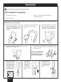
Models:
Owner’s manual:
Read this manual for complete instructions
Table of Contents
This pump is available in a stand model (9140S) and cart models (9146,
9150, 9170 and 9190). All information given for the stand model applies
to the cart models except where indicated.
1-800-880-0993
Safety . . . . . . . . . . . . . . . . . . . . . . . . . . . . . . . . . . . .2-3
Components and Description . . . . . . . . . . . . . . . .4-5
Assembly . . . . . . . . . . . . . . . . . . . . . . . . . . . . . . . . . . .6
Before You Begin . . . . . . . . . . . . . . . . . . . . . . . . . . . .7
Locking the Spray Gun . . . . . . . . . . . . . . . . . . .7
Plugging in the Sprayer . . . . . . . . . . . . . . . . . . .7
Pressure Relief Procedure . . . . . . . . . . . . . . . .7
Purging and Priming the Sprayer . . . . . . . . . . . . . . .8
Purging and Priming the Spray Hose . . . . . . . . . . .9
Practice / Spraying Technique . . . . . . . . . . . . . . . .10
Spraying Troubleshooting . . . . . . . . . . . . . . . . .11-12
Unclogging the Spray Tip . . . . . . . . . . . . . . . .11
Cleaning the Spray Gun Filter . . . . . . . . . . . . .12
Cleaning the Inlet Filter . . . . . . . . . . . . . . . . . .12
Cleanup . . . . . . . . . . . . . . . . . . . . . . . . . . . . . . . .13-17
Cleanup for Latex materials . . . . . . . . . . . .13-14
Cleanup for Oil-based materials . . . . . . . . . . .15
Cleaning the Suction Set . . . . . . . . . . . . . . . . .16
Cleaning the Spray Gun Components . . . . . .17
Short-Term Storage . . . . . . . . . . . . . . . . . . . . . . . . .18
Long-Term Storage . . . . . . . . . . . . . . . . . . . . . . . . . .19
Cleaning the Inlet Valve . . . . . . . . . . . . . . . . . . . . . .20
Fluid Section . . . . . . . . . . . . . . . . . . . . . . . . . . . . . . .21
Troubleshooting / Maintenance . . . . . . . . . . . . . . .22
Français . . . . . . . . . . . . . . . . . . . . . . . . . . . . . . . . . . .23
Español . . . . . . . . . . . . . . . . . . . . . . . . . . . . . . . . . . .45
Parts List . . . . . . . . . . . . . . . . . . . . . . . . . . . . . . .67-70
Accessories . . . . . . . . . . . . . . . . . . . . . . . . . . . . . . .71
Warranty . . . . . . . . . . . . . . . . . . . . . . . . . . . . . . . . . .72
Wagner Technical Service
Visit us on the world wide web!
Need Help? Call us first for answers
fast. Call Wagner Spray Tech toll-free if you
http://www.wagnerspraytech.com
have any comments or problems with this product.
1770 Fernbrook Lane, Plymouth, MN 55447
Technical service hours: Monday through Friday, 8:00 am to 4:30 pm Central Time
0507 •
Form No. 0516927E
English
Important Safety Information • Read all safety information before
operating the equipment. Save these instructions
To reduce the risks of fire or explosion, electrical shock and the injury to persons, read and understand all instructions included in
this manual. Be familiar with the controls and proper usage of the equipment.
Indicates a hazardous situation which, if not avoided, could
result in death or serious injury.
HAZARD: EXPLOSION OR FIRE
Solvent and paint fumes can explode or ignite. Property
damage and/or severe injury can occur.
HAZARD: INJECTION INJURY
A high pressure paint stream produced by this
equipment can pierce the skin and underlying tissues,
leading to serious injury and possible amputation. SEE A
PHYSICIAN IMMEDIATELY.
DO NOT TREAT AN INJECTION INJURY AS A SIMPLE CUT!
Injection can lead to amputation. See a physician immediately.
The maximum operating range of the gun is 3000 PSI/207 BAR
fluid pressure.
PREVENTION:
• Provide extensive exhaust and fresh air introduction to keep the air
within the spray area free from accumulation of flammable vapors.
Solvent and paint fumes can explode or ignite.
• Do not spray in a confined area.
• Avoid all ignition sources such as static electric
sparks, open flames, pilot lights, electrical appliances,
and hot objects. Connecting or disconnecting power cords or
working light switches can make sparks. Paint or solvent flowing
through the equipment is able to result in static electricity.
• Do not smoke in spray area.
• Fire extinguisher must be present and in good working order.
• Place paint pump at least 20 feet from the spray object in a well
ventilated area (add more hose if necessary). Flammable vapors
are often heavier than air. Floor area must be extremely well
ventilated.
• The equipment and objects in and around the spray area must be
properly grounded to prevent static sparks.
• Keep area clean and free of paint or solvent containers, rags and
other flammable materials.
• Use only conductive or grounded high pressure fluid hose. Gun
must be grounded through hose connections.
• Power cord must be connected to a grounded circuit.
• Always flush unit into a separate metal container, at low pump
pressure, with spray tip removed. Hold gun firmly against side of
container to ground container and prevent static sparks.
• Follow the material and solvent manufacturer's warnings and
instructions. Know the contents of the paints and solvents being
sprayed. Read all Material Safety Data Sheets (MSDS) and
container labels provided with the paints and solvents. Follow the
paint and solvent manufacturer’s safety instructions.
• Use extreme caution when using materials with a flashpoint below
70ºF (21ºC). Flashpoint is the temperature that a fluid can produce
enough vapors to ignite.
• Plastic can cause static sparks. Never hang plastic to enclose a
spray area. Do not use plastic drop cloths when spraying
flammable materials.
• Use lowest possible pressure to flush equipment.
• Do not spray onto pump assembly.
PREVENTION:
• NEVER aim the gun at any part of the body.
• Do not aim the gun at, or spray any person or animal.
• NEVER allow any part of the body to touch the fluid stream. DO
NOT allow body to touch a leak in the fluid hose.
• NEVER put your hand in front of the gun. Gloves will not provide
protection against an injection injury.
• ALWAYS lock the gun trigger, shut the pump off, and release all
pressure before servicing, cleaning the tip or guard, changing tip,
or leaving unattended. Pressure will not be released by turning off
the motor. The PRIME/SPRAY knob must be turned to PRIME to
relieve the pressure. Refer to the PRESSURE RELIEF
PROCEDURE (page 7) described in the pump manual.
• ALWAYS keep the tip guard in place while spraying. The tip guard
provides some protection but is mainly a warning device.
• ALWAYS remove the spray tip before flushing or cleaning the
system.
• Paint hose can develop leaks from wear, kinking and abuse. A
leak can inject material into the skin. Inspect the hose before each
use. Do not use hose to lift or pull equipment.
• NEVER use a spray gun without a working trigger lock and trigger
guard in place.
• All accessories must be rated at or above 3000 PSI/207 BAR.
This includes spray tips, guns, extensions, and hose.
NOTE TO PHYSICIAN:
Injection into the skin is a traumatic injury. It is important to treat
the injury as soon as possible. DO NOT delay treatment to
research toxicity. Toxicity is a concern with some coatings
injected directly into the blood stream. Consultation with a plastic
surgeon or reconstructive hand surgeon may be advisable.
HAZARD: EXPLOSION HAZARD DUE TO
INCOMPATIBLE MATERIALS
Will cause property damage or severe injury.
HAZARD: HAZARDOUS VAPORS
Paints, solvents, insecticides, and other materials can be
harmful if inhaled or come in contact with the body.
Vapors can cause severe nausea, fainting, or poisoning.
PREVENTION:
• Do not use materials containing bleach or chlorine.
• Do not use halogenated hydrocarbon solvents such as bleach,
mildewcide, methylene chloride and 1,1,1 - trichloroethane. They
are not compatible with aluminum.
• Contact your coating supplier about the compatibility of material
with aluminum.
PREVENTION:
• Use a respirator or mask if vapors can be inhaled.
Read all instructions supplied with the mask to be
sure it will provide the necessary protection.
• Wear protective eyewear.
• Wear protective clothing as required by coating manufacturer.
English
2
Important Safety Information • Read all safety information before
operating the equipment. Save these instructions
NOTICE
HAZARD: GENERAL
Can cause severe injury or property damage.
THE 9140S, 9146 AND 9150 SERIES UNITS ARE PROVIDED WITH A
NON-RESETABLE THERMAL OVERLOAD. THE 9170 AND 9190
SERIES UNITS ARE PROVIDED WITH A REPLACEABLE FUSE.
• Always disconnect the motor from the power supply before working
on the equipment.
PREVENTION:
• Read all instructions and safety precautions before operating
equipment.
• Follow all appropriate local, state, and national codes governing
ventilation, fire prevention, and operation.
• The United States Government Safety Standards have been
adopted under the Occupational Safety and Health Act (OSHA).
These standards, particularly part 1910 of the General Standards
and part 1926 of the Construction Standards should be consulted.
• Use only manufacturer authorized parts. User assumes all risks
and liabilities when using parts that do not meet the minimum
specifications and safety requirements of the pump manufacturer.
• Before each use, check all hoses for cuts, leaks, abrasion or
bulging of cover. Check for damage or movement of couplings.
Immediately replace the hose if any of these conditions exist.
Never repair a paint hose. Replace it with another grounded highpressure hose.
• All hoses, fittings, and filter caps must be secured before operating
spray pump. Unsecured parts may eject at great force or leak a
high pressure fluid stream causing severe injury.
• All hoses, swivels, guns, and accessories must be pressure rated
at or above 3000 PSI/207 BAR.
• Do not spray outdoors on windy days.
• Wear clothing to keep paint off skin and hair.
• Do not operate or spray near children. Keep children away from
the equipment at all times.
• Do not overreach or stand on an unstable support. Keep effective
footing and balance at all times.
• Stay alert and watch what you are doing.
• Do not operate the unit when fatigued or under the influence of
drugs or alcohol.
The cause of the overload should be corrected before
restarting. Take unit to Service Center.
Grounding Instructions
This product must be grounded. In the event of an electrical short
circuit, grounding reduces the risk of electric shock by providing an
escape wire for the electric current. This product is equipped with a
cord having a grounding wire with an appropriate grounding plug. The
plug must be plugged into an outlet that is properly installed and
grounded in accordance with all local codes and ordinances.
Improper installation of the grounding plug can
result in a risk of electric shock.
If repair or replacement of the cord or plug is necessary, do not connect
the green grounding wire to either flat blade terminal. The wire with
insulation having a green outer surface with or without yellow stripes is
the grounding wire and must be connected to the grounding pin.
Check with a qualified electrician or serviceman if the grounding
instructions are not completely understood, or if you are in doubt as to
whether the product is properly grounded. Do not modify the plug
provided. If the plug will not fit the outlet, have the proper outlet
installed by a qualified electrician.
This product is for use on a nominal 120 volt circuit and has a
grounding plug that looks like the plug illustrated below. Make sure that
the product is connected to an outlet having the same configuration as
the plug. No adapter should be used with this product.
Important Electrical Information
Grounded Outlet
NOTICE
Use only a 3-wire extension cord that has a 3-blade grounding plug and
a 3-slot receptacle that will accept the plug on the product. Make sure
your extension cord is in good condition. When using an extension
cord, be sure to use one heavy enough to carry the current your
product will draw. An undersized cord will cause a drop in line voltage
resulting in loss of power and overheating. A 14 or 12 gauge cord is
recommended (see chart below). If an extension cord is to be used
outdoors, it must be marked with the suffix W-A after the cord type
designation. For example, a designation of SJTW-A would indicate that
the cord would be appropriate for outdoor use.
Cord gauge
Maximum cord length
12
200 feet
14
100 feet
Grounding Pin
Cover for grounded outlet box
If you experience problems with your
sprayer at any time during assembly,
operation, or cleanup, please refer to
the Troubleshooting section of this
manual (page 22), or call customer
service at:
1-800-880-0993
Do not use more than 100 feet of spray hose. If you need to
spray further than 100 feet from your power source, use
more extension cord, not more spray hose.
3
English
Components and Description
Components
The shipping carton for your painting system contains the following:
• Suction tube and return tube
• Separating Oil
• Pump cleaning adapter
• Instruction manual
• Spray gun with filter
• Hose bracket (all cart units)
• Spray tip assembly (see chart on next page)
• Pail bracket (all cart units)
• 25’ (9140S, 9146, 9150) or 50’ (9170, 9190), 1/4” diameter pressure hose
Controls and Functions
ON/OFF Switch. . . . . . . . . . . The ON/OFF switch turns the power to the sprayer on and off (O=OFF, l=ON).
Suction tube . . . . . . . . . . . . . Fluid is drawn through the suction tube into the pump.
Fluid Section . . . . . . . . . . . . A piston in the fluid section moves up and down to create the suction that draws fluid through the
suction tube.
Spray Gun. . . . . . . . . . . . . . . The spray gun controls the delivery of the fluid being pumped. The gun model you have depends on
your sprayer model (refer to Spray Gun/Tip Chart, next page).
Spray Hose . . . . . . . . . . . . . . The spray hose connects the gun to the pump.
Return Tube . . . . . . . . . . . . . Fluid is sent back out through the return tube to the original container when PRIME/SPRAY knob is in
PRIME position.
Pump Cleaning Adapter . . . The adapter allows you to attach a garden hose to the suction tube for easy cleanup (latex materials
only).
PRIME/SPRAY Knob . . . . . . The PRIME/SPRAY knob directs fluid to the spray hose when set to SPRAY or the return tube when set
to PRIME. The arrows on the PRIME/SPRAY knob shows the rotation directions for PRIME and
SPRAY.
The PRIME/SPRAY knob is also used to relieve pressure built up in the spray hose (see Pressure
Relief Procedure, page 7).
Pressure Control Dial . . . . . The pressure control dial regulates the amount of force the pump uses to push the fluid.
Oiler . . . . . . . . . . . . . . . . . . . . (9150, 9170, 9190 only) The oiler is designed to provide lubrication to the fluid section of the pump.
Pusher Stem . . . . . . . . . . . . . The pusher stem is designed to keep the inlet valve open and from sticking due to dried materials.
Specifications
Capacity
Generator power
requirement.....................8000 Watt
9140S, 9146 .............Up to .25 gallon (0.95 liter) / minute
9150..........................Up to .29 gallon (1.10 liters) / minute
Safety features................Spray gun trigger lock and pressure
diffuser; built-in tip safety guard;
PRIME/SPRAY knob for safe pressure
release.
9170 .........................Up to .33 gallon (1.25 liters) / minute
9190..........................Up to .42 gallon (1.60 liters) / minute
Power source
Capability ........................Sprays a variety of paints, oil base
latex, primers, stains, preservatives
and other nonabrasive materials,
including pesticides and liquid
fertilizers.
This pump should not be used with
textured materials, block filler, or
asphalt sealer.
9140S, 9146 .............1/2 Hp universal motor
9150..........................5/8 Hp universal motor
9170..........................3/4 Hp permanent magnet DC motor
9190 .........................7/8 Hp permanent magnet DC motor
Power requirement.........15 amp minimum circuit on 115 VAC,
60 Hz current
English
4
Components and Description
This pump is available in two models: a stand model (9140S) and cart models (9146, 9150 shown below, 9170 and 9190). All
information given for the stand model applies to the cart models except where indicated.
Important
Some of the graphics in this manual may not exactly match your sprayer and spray gun. All information and instructions
given in this manual applies to all models except where noted.
9140S, 9146
9150
9170
9190
GX-05
GX-07
GX-07
GX-08
415
415
517
517
415
517
519
521
Yellow (fine)
Yellow (fine)
White (medium)
White (medium)
25 feet
25 feet
50 feet
50 feet
Hose bracket
Spray hose
Pressure control dial
(rear of sprayer)
Oiler (9150, 9170
and 9190 only)
Spray hose port
(reverse side)
ON / OFF switch*
(reverse side)
PRIME/SPRAY
knob
Pail bracket
Return tube
fitting
Pusher stem
Return tube
**The pump cleaning
adapter can be clipped
to the spray hose port
Suction tube
Spray gun (see chart above
for models, GX-07 shown)
Clip
Suction set filter
Spray
guard
Pump cleaning
adapter**
Spray tip
(see chart above
for models)
5
English
Assembly
Do not plug in the sprayer until setup is complete.
Tools needed for assembly:
• Extension cord (refer to Important Electical
Information (page 3).
• Two adjustable wrenches
• 3/16” Allen wrench
If you have one of the cart models (9146, 9150, 9170 or 9190), follow these assembly instructions. If you have the model
9140S sprayer, skip to item 4, below.
1. Twist the knobs on either side of the
handle counterclockwise to unlock
the handle. Pull the handle out fully,
and turn knobs clockwise to lock
into place.
2. Insert the ends of the hose bracket
into the holes of the handle as
shown.
3. Attach the pail bracket. Line up the
holes in the bracket with the holes in
the sprayer. Insert and tighten the
screws using a 3/16” allen wrench.
5. Thread the other end of the hose to the spray gun. Hold
the gun with one adjustable wrench, and tighten the hose
nut with the other.
4. Thread the high pressure hose to the spray hose port.
Tighten with an adjustable wrench.
The spray tip SHOULD NOT
be attached until after the
sprayer and spray hose have
been purged and primed.
6. Remove cap from inlet
valve (a). Thread the
suction tube onto the
inlet valve and tighten
firmly by hand. Be
sure that the threads
are straight so that the
fitting turns freely.
7. Press the return
tube onto the
return tube fitting.
Squeeze clip
over the return
tube fitting to
secure the return
tube.
(a)
English
6
8. Verify that the seal is
present inside the
suction tube. Thread
the inlet filter into the
end of the suction
tube.
Before you begin -
This section contains instructions that
will be repeated throughout this manual.
Locking the Spray Gun:
Always lock the trigger off when attaching the spray tip or when the spray gun is not in use.
Model GX-05 and GX-07 Spray Gun
Model GX-08 Spray Gun
The gun is locked when the trigger lock is at a 90º
angle (perpendicular to the trigger in either direction).
To lock the gun, turn the trigger lock forward and
slightly down until it stops.
GX-05
GX-07
Plugging in the Sprayer:
2. Plug the power cord into a grounded outlet or heavy duty
grounded extension cord. Plug in the extension cord.
Refer to Important Electrical Information, page 3.
1. Check that the ON/OFF switch is in the OFF (O) position.
O
Pressure Relief Procedure:
Be sure to follow the Pressure Relief Procedure when shutting the unit off FOR ANY PURPOSE. This procedure
is used to relieve pressure from the spray hose.
1. Lock the spray gun off (see
directions above). Move the
ON/OFF switch to the OFF position.
2. Turn the PRIME/SPRAY knob to
PRIME.
3. Unlock the spray gun and trigger
spray gun into the side of the
material bucket. Lock the spray
gun.
7
PRIME
SPRAY
O
English
Purging and Priming the Sprayer
All new units are performance-tested at the factory and are shipped with test fluid in the fluid section to prevent
corrosion during shipment and storage. If you have already used your pump, some water or solvent used in cleaning
may remain in the fluid section. Whether your sprayer is new or if you have already used it, this fluid must be purged
and thoroughly cleaned out of the system prior to use. Follow the steps below.
9150, 9170 and 9190 only.
1. Remove oiler cap using a straightslot screwdriver. Squirt separating
oil (P/N 0516913) supplied with your
sprayer into the oiler. Light
household oil can be substituted if
necessary. Replace cap.
2. After filling, push button on front of
face plate 2-5 times to lubricate the
fluid section. Afterwards, press
once for every eight hours of usage.
Be sure to periodically check
reservoir level (a) and refill as
necessary.
3. Fully depress the pusher stem to
make sure the inlet ball is free.
(a)
5. Turn the pressure control dial to maximum pressure (+).
Turn the PRIME/SPRAY knob to PRIME.
PRIME
SPRAY
4. Place a full container of spraying material underneath the
suction tube (a). Secure the return tube (b) into a waste
container.
(a)
(b)
7. Switch the pump OFF (O). Remove the return tube from
the waste container and place it in its operating position
above the container of spraying material. Use the metal
clip to bind the two hoses together.
6. Plug in the sprayer and move the ON/OFF switch to the
ON (l) position.
l
The unit will begin to draw material up the suction tube,
into the pump, and out the return tube. Let the unit cycle
long enough to remove test fluid from the pump, or until
spray material is flowing from the return tube.
English
8
Purging and Priming the Spray Hose
2. PULL the trigger and aim the spray gun at the side wall of
a waste container. If using oil-based materials, the
spray gun must be grounded while purging (see
warning below).
PRIME
The spray tip SHOULD NOT
be attached to the spray
gun when purging the
spray hose.
SPRAY
1. Unlock the spray gun and turn the PRIME/SPRAY knob to
PRIME.
Keep hands clear from fluid stream.
Ground the gun by holding it against the edge of a metal container while flushing. Failure to do so may lead
to a static electric discharge which may cause a fire.
3. While pulling the trigger, switch the pump ON (l), AND
turn the PRIME/SPRAY knob to SPRAY. Hold the
trigger until all air, water, or solvent is purged from
the spray hose and material is flowing freely.
SPRAY
PRIME
If the PRIME/SPRAY knob is still on SPRAY,
there will be high pressure in the hose and
spray gun until the PRIME/SPRAY knob is
turned to PRIME.
4. Release trigger. Turn the PRIME/SPRAY knob to PRIME.
Turn the pump OFF (O). Trigger the gun into the waste
container to be sure that no pressure is left in the hose.
5. Lock the spray gun off. Thread the spray tip guard
assembly onto the gun. Tighten by hand.
Begin
tightening
the tip at
this angle
PRIME
SPRAY
O
9
. . .to achieve
the desired
spray angle
when tight.
English
Practice / Spraying Technique
NOTE - Be sure that the paint hose is free of kinks and clear of objects with sharp cutting edges.
2. When motor shuts off, unlock the spray gun and spray a
test area to check the spray pattern.
1. Switch the pump ON (l). Turn the PRIME/SPRAY knob to
SPRAY. Turn the pressure control dial to maximum
pressure (+). The spray hose should stiffen as paint
begins to flow through it.
The motor will cycle on and off automatically as the pump
needs pressure.
The pressure control dial can be be adjusted up or down
to achieve the desired spray pattern.
SPRAY
PRIME
l
Good spray pattern
Paint tailing pattern
(pressure too low,
clogged tip)
The key to a good job is an even coating over the entire surface.
This is done by using even strokes. Follow the TIPS, below.
Light Coat
Tip:
Heavy Coat
Light Coat
Keep the spray gun at right angles to the
surface. This means moving your entire
arm back and forth rather than just flexing
your wrist.
Approximately
10 to 12 inches
Tip:
Keep the spray gun perpendicular to the
surface, otherwise one end of the pattern
will be thicker than the other.
Tip:
Trigger gun after starting the stroke. Release
the trigger before ending the stroke. The
spray gun should be moving when the trigger
is pulled and released. Overlap each
stroke by about 30%. This will ensure an
even coating.
Wrong way
Right way
Keep stroke
even
If you expect to be away from your sprayer for more than
one hour, follow the Short-Term Storage instructions
(page 18).
English
Start
stroke
10
Pull
trigger
Approximately
10 to 12 inches
Move
steadily
Release
trigger
End
stroke
Spraying Troubleshooting -
Unclogging the Spray Tip
If the spray pattern becomes distorted or stops completely while the gun is triggered, follow these steps.
Do not attempt to unclog or clean the tip with your finger.
NOTE - Do not use a needle or other sharp pointed instrument to clean the tip. The hard tungsten carbide can chip.
Gun locked
(see page 7)
1. Release the trigger and lock the gun off (see page 7).
Rotate the reversible tip arrow 180º so that the point of
the arrow is toward the rear of the gun (CLEAN position).
GX-05 / GX-07
Under pressure, the spray tip may be very difficult to
turn. Turn the PRIME/SPRAY knob to PRIME and
trigger the gun. This will relieve pressure and the tip
will turn more easily.
GX-08
SPRAY
2. Turn the PRIME/SPRAY knob to SPRAY.
PRIME
3. Unlock the gun and squeeze the trigger, pointing the gun
at a scrap piece of wood or cardboard. This allows
pressure in the spray hose to blow out the obstruction.
When the nozzle is clean, material will come out in a
straight, high pressure stream.
If material still will not spray from the spray tip, follow
the Cleaning the spray gun filter instructions, page 12.
Gun locked
(see page 7)
GX-05 / GX-07
4. Release the trigger and lock the gun off (see page 7).
Reverse the tip so the arrow points forward again (SPRAY
position). Unlock the gun and resume spraying.
GX-08
11
English
Spraying Troubleshooting -
Cleaning the Spray Gun Filter
The filter must be cleaned every time you use your sprayer. When using thicker spray materials, the filter might need to
be cleaned more often.
Spray gun model
GX-07
1. Perform Pressure Relief Procedure, page 7.
2a. Model GX-07 - Unscrew the fitting from the bottom of the
spray gun using an adjustable wrench, making sure not to
lose the spring.
Tapered
end
(filter top)
Filter
Hole
2b. Models GX-05 and GX-08 - Unclip the trigger guard from
the filter housing by pulling outward from the filter
housing. Unscrew the filter housing.
Spring
Fitting
3. Remove the filter from the spray gun housing and clean
with the appropriate cleaning solution (warm, soapy water
for latex paints, mineral spirits for oil-based materials).
4. Inspect the filter for holes (see inset, right). Replace if
holes are found.
Spray gun models
GX-05 and GX-08
NOTE - NEVER POKE THE FILTER WITH A SHARP
INSTRUMENT!
Tapered
end
(filter top)
5. Replace the cleaned filter, tapered end first, into the gun
housing. The tapered end of the filter must be loaded
properly into the gun. Improper assembly will result
in a plugged tip or no flow from the gun.
Hole
6. Reassemble the spray gun.
Trigger
guard
Spraying Troubleshooting -
Filter
Filter
housing
Cleaning the Inlet Filter
The filter at the bottom of the suction tube may also need cleaning. Check it every time you change spray containers.
1. Remove the filter by unscrewing it from the suction tube.
Clean the filter with the appropriate cleaning solution
(warm, soapy water for latex materials, mineral spirits for
oil-based materials).
2. Thread the filter back into place.
If after completing all of the steps in Spraying
Troubleshooting you are still experiencing problems
spraying, refer to the Troubleshooting section (page 22).
English
12
Important Cleaning Notes!
Read these notes and warnings before you start to clean your sprayer!
• When using latex materials, clean your sprayer and
components with water. When using oil-based
materials, use mineral spirits.
Follow these steps whenever cleaning with
mineral spirits:
• Always flush spray gun at least one hose length
away from spray pump.
• Do not use mineral spirits on latex materials, or the
mixture will turn into a jelly-like substance which is
difficult to remove.
• If collecting flushed solvents in one gallon metal
container, place it into an empty five gallon
container, then flush.
• No matter which cleaning solution you use, make sure
to dispose of it properly when finished cleaning your
sprayer.
• Area must be free from vapors.
• Follow all cleanup instructions.
• Thorough cleaning and lubrication of the sprayer is
the most important step you can take to ensure proper
operation after storage.
• DO NOT use gasoline to clean your sprayer.
Call 1-800-880-0993 if you have any problems or questions regarding the cleaning of your sprayer.
Cleanup -
Latex materials
Follow these steps if you used latex materials AND if you have a garden hose available. If you do not have a garden
hose available, follow the Cleanup - Oil-Based Materials instructions.
1. Lock the gun and remove the spray tip assembly. Place
the suction tube and return tube into an empty waste
container.
2. Using a garden hose, rinse off the suction tube, return
tube and inlet filter. Empty the waste container.
Empty waste
container
3. Remove the inlet filter from the suction tube and place
into the waste container.
4. Verify that the seals are
present inside the
adapter and suction tube
(a). Thread the pump
cleaning adapter (b) onto
a garden hose (c).
Connect hose and
adapter to the fitting on
the end of the suction
tube (d).
(d)
(b)
(a)
(c)
Continued on next page.
13
English
Cleanup -
Latex materials (continued)
6. Turn water supply on. Turn pump ON (l). Water will go
into the suction tube and out through the return tube. Let
pump run for a few minutes to allow the return tube to be
flushed.
Leave pump running
through steps 7 and 8.
PRIME
SPRAY
5. Unclip the return tube from the suction tube and place it
into the waste container. Turn the PRIME/SPRAY knob to
PRIME.
7. Place the original material container next to the waste
container. Aim the spray gun into the side of the original
material container and hold the trigger.
8. While pulling the trigger, turn the PRIME/SPRAY knob to
SPRAY to purge material from the hose back into the
original container.
SPRAY
PRIME
Hold trigger
Waste
container
Containers should
be touching
Original
material
container
Keep holding trigger through next steps.
Ho
ld t
r
igg
e
r
9. When cleaning solution flows from the spray gun, keep
holding the trigger and aim the spray gun into the side of
the waste container.
10. Trigger the gun until the fluid flowing out of the gun is
clear. You may need to empty the waste container and
continue flushing.
Spray water into
waste container
11. Turn the PRIME/SPRAY knob to PRIME and trigger gun
to relieve pressure.
Spray material
into original container
Move on to Cleaning the Spray Gun Components.
English
14
Cleanup -
Oil-based materials
2. Place a waste container next to the original material
container. Aim the spray gun into the side of the original
material container and hold the trigger.
1. Lock the gun and remove spray tip assembly. Submerge
suction set into a bucket with appropriate cleaning
solution.
Hold trigger
Waste
container
Original
material
container
Containers should
be touching
Bucket with
cleaning
solution
• Hold trigger
• Turn pump ON (l)
• Turn PRIME/SPRAY knob to SPRAY
3. While pulling the gun trigger, turn the pump ON (l), and turn
the PRIME/ SPRAY knob to SPRAY to purge material from
the hose back into the original container.
Keep holding trigger through next steps.
Ho
ld t
4. When cleaning solution flows from the spray gun, keep
holding the trigger and aim the spray gun into the side of the
waste container (ground gun with a metal container if
flushing with flammable solvent).
5. Trigger the gun until the fluid flowing out of the gun is
clear. You may need to dispose and obtain new cleaning
solution.
Spray cleaning solution
into waste container
6. Turn the PRIME/SPRAY knob to PRIME and trigger gun
to relieve pressure.
Spray material into
original container
Move on to Cleaning the Suction Set.
15
English
rigg
er
Cleanup -
Cleaning the Suction Set
2. Remove the suction hose and return tube and clean it
using the appropriate cleaning solution. You should also
wipe the threads of the inlet nut (a) and remove and clean
the inlet filter of the suction tube.
1. Lock the gun and turn the pump OFF (O).
GX-05
GX-07
O
(a)
GX-08
4. Submerge the suction set into a bucket of NEW cleaning
solution.
5. Turn the PRIME/SPRAY knob to PRIME. Turn the pump
ON (l), and trigger the gun once into a waste container to
relieve pressure.
6. Let the pump circlulate cleaning solution through the suction
set for 2-3 minutes. Turn the pump OFF.
PRIME
SPRAY
3. When suction set is clean, thread the suction tube back
into the inlet valve, and replace the return tube onto the
return tube fitting. Replace clip.
l
2 to 3
minutes
IMPORTANT!
If you used oil-based materials, you must flush the pump
again using water to prepare it for storage. Repeat #1 - #11
in Cleanup- Latex materials, instructions.
Move on to Cleaning the Spray Gun Components.
English
16
Cleanup -
Cleaning the Spray Gun Components
1. Make sure the pump is switched OFF (O). Make sure the
PRIME/SPRAY knob is turned to PRIME. Unplug the
sprayer.
2. Remove spray gun from the paint hose using adjustable
wrenches.
PRIME
SPRAY
O
3. Remove filter from spray gun (refer to Cleaning the
Spray Gun Filter, page 12).
GX-07
4. Remove spray tip (a) from spray guard assembly. Clean
spray tip with a soft-bristled brush and the appropriate
cleaning solution. Be sure to remove and clean the
washer (b) and saddle seat (c) located in the rear of the
spray tip assembly.
GX-05
GX-08
(b)
(c)
(a)
6. Install spray tip (a), saddle seat (c) and washer (b), and
replace spray guard assembly.
5. Install gun filter tapered-end first. Reassemble spray gun.
GX-07
GX-05
GX-08
(b)
(c)
(a)
7. Thread the spray gun back onto the paint hose. Tighten
with a wrench.
17
English
Short-Term Storage (up to 16 hours)
Follow these steps when using latex materials only. If using materials that are oil-based, follow the Cleanup - Oil-based
materials and Long-Term Storage steps.
Shutdown
1. Lock the spray gun off.
GX-05
GX-07
2. Turn the PRIME/SPRAY knob to PRIME. Switch the pump
OFF (O). Unplug the sprayer.
3. Pour 1/2 cup water slowly on the top of the paint to
prevent the paint from drying. Wrap the spray gun
assembly in a damp cloth and place it in a plastic bag.
Seal the bag shut. Place the sprayer in a safe place out
of the sun for short-term storage.
O
PRIME
SPRAY
GX-08
Startup
2. Turn the PRIME/SPRAY knob to PRIME. Plug sprayer in.
Turn the switch to ON (I).
3. Turn the PRIME/SPRAY knob to SPRAY. Test the
sprayer on a practice piece and resume spraying.
English
18
PRIME
SPRAY
1. Remove the gun from the plastic bag. Stir the water into
the paint.
l
Long-Term Storage
Follow these instructions only after all cleanup steps have been performed.
1. Fill a cup or other container with separating oil
(approximately 2 ounces) supplied with the unit and
submerge the inlet valve into the oil. Light household oil
can be substituted.
2. Place a rag over the spray hose port, and turn the switch
ON (l). When the oil has been sucked from the cup, turn
the pump OFF (O).
Separating oil
3. Wipe the entire unit, hose and gun with a damp cloth to
remove accumulated paint. Replace the high pressure
hose to the paint hose port.
If you have a cart model (9146, 9150, 9170, 9190), you can collapse the cart handle for easier storage.
1. Twist the knobs on either side of the cart
counterclockwise.
2. Slide the handle into the cart.
19
English
Cleaning the Inlet Valve
Cleaning or servicing the inlet valve may be required if the unit has priming problems. Priming problems may be
prevented by properly cleaning the sprayer and following the long-term storage steps.
2. Unscrew the inlet valve assembly (a) from the sprayer.
Visually inspect the inside and outside of the inlet valve
assembly. Clean any paint residue with the appropriate
cleaning solution.
1. Remove the suction set.
(a)
3. Lubricate the O-ring on the inlet valve (b). Replace inlet
valve assembly by screwing it into the sprayer. Torque to
23-27 ft lbs (9140, 9146, 9150) or 32-38 ft lbs (9170, 9190).
4. Replace suction set and hand-tighten.
(b)
If priming problems persist, you may need to replace the
inlet valve assembly. Call Customer Service to order a
new inlet valve assembly.
English
20
Fluid Section Seal Replacement Instructions
Kit Part Number 0512228A (9140S, 9146, 9150)
Kit Part Number 0516725 (9170, 9190)
Always wear protective eye wear while servicing the pump. Be sure to follow the Pressure Relief Procedure
(page 7) when shutting the unit down for any purpose, including servicing or adjusting. After performing the
Pressure Relief Procedure, be sure to unplug the unit before servicing or adjusting. Area must be free of
solvents and paint fumes.
Disassembly of the Fluid Section
1. Remove the suction set.
2. Remove the front cover and the four screws that secure it
using a T20 Torx head driver.
3. Remove the yoke screw and washer that secures the dowel
pin. The dowel pin connects the yoke to the piston.
4. Using a pliers, pull the dowel pin out.
5a. For models 9140S, 9146, and 9150, rotate the pump shaft
so the piston is in the top dead center position. This can be
done by pushing on the yoke. This is required to
disassemble all the parts.
5b. For models 9170 and 9190, inspect the yoke assembly
and piston. In order to remove all the necessary parts, the
piston must not be in the bottom dead center position. If
the piston is at the bottom of the stroke, install the front
cover and screws, turn the pump on briefly to index the
piston, unplug the unit, and repeat step 2.
6. Unscrew and remove the inlet valve assembly (see page
20).
7. Remove the piston assembly by pushing down on the
piston near the yoke.
8. Unscrew and remove the top nut using and adjustable
wrench.
9. Remove the worn seals using a flat head screwdriver or
punch. Remove the top seal from the top and the bottom
seal from the bottom by pressing against the side of the
seal and popping it out. Be sure not to scratch the housing
where the seals are located.
10. Clean the area where the new seals are to be installed.
5.
6.
7.
8.
9.
10.
11.
(inlet) of the housing, and tighten with an adjustable
wrench. This will drive the bottom seal into the correct
position.
Align the piston with the yoke. Be careful not to damage
the piston.
Apply a lithum grease to the holes in the yoke where the
dowel is inserted.
Install the dowel pin to connect the yoke to the piston. The
piston may have to be moved up or down to do this. The
inlet valve may need to be removed again to move the
piston.
Install the yoke screw and washer to secure the dowel pin.
Turn pump right side up and apply a few drops of
Separating Oil or light household oil between the top nut
and piston. This will prolong the seal life.
Install front cover and four (4) screws.
Replace inlet valve. Install the suction set.
Top nut
Top seal
(cup down)
0512228A Kit
(9140S, 9146
and 9150)
0516724 Kit
(9170, 9190)
Yoke
Screw
Assembly of the Fluid Section
Dowel
1. Lubricate the new top seal with Separating Oil (P/N
0516913) or light household oil and by hand place the seal
(cup side of seal down) into the top port of the housing.
2. Place a small amount of anit-seize on the threads of the top
nut. Place the top nut into the top of the housing and
tighten with an adjustable wrench. This will drive the top
seal into the correct position.
Washer
Piston/seal
assembly
3. Turn the pump upside down.
Lubricate the seal on the
piston/seal assembly similar to
the top seal. Place the
piston/seal assembly into the
bottom of the housing. Insert
the plastic insertion tool and
thread into position to properly
seat the piston/seal. Thread
fully until tight. Remove the
insertion tool.
4. Install the new O-ring on the inlet valve assembly, lubricate
with Separating Oil (P/N 0516913), thread into the bottom
Insertion
tool
0512228A Kit
(9140S, 9146
and 9150)
NOTE - DO NOT
attempt to remove the
seals from the piston.
0516724 Kit
(9170, 9190)
O-ring
Inlet valve assembly
0516292 (9140S,9146, 9150)
0516296 (9170, 9190)
21
English
Troubleshooting / Maintenance
Problem
Cause
A. The sprayer does not start.
Solution
1. The sprayer is not plugged in.
2. The ON/OFF switch is set to OFF.
3. The sprayer was turned off while still under
pressure.
4. No voltage is coming from the wall plug.
5. The extension cord is damaged or has too
low a capacity.
6. A fuse is blown in the sprayer.
7. There is a problem with the motor.
B. The sprayer starts but does
not draw in paint when the
PRIME/SPRAY knob is set to
PRIME.
1. The paint bucket is empty or the suction
tube is not totally immersed in the paint.
2. The suction set is clogged.
3. The suction tube is loose at the inlet valve.
4. The inlet valve is stuck.
5. The outlet valve is stuck.
6. The inlet valve is worn or damaged.
7. The PRIME/SPRAY valve is plugged.
C. The sprayer draws up paint
but the pressure drops when
the gun is triggered.
1. The spray tip is worn.
2. The suction set screen is clogged.
3. The gun filter is plugged.
1. Plug the sprayer in.
2. Turn the ON/OFF switch to ON.
3. Turn the pressure control knob to maximum
pressure (+), or relieve pressure by turning the
PRIME/SPRAY valve to PRIME.
4. Properly test the power supply voltage.
5. Replace the extension cord.
6. Take sprayer to Authorized Service Center.
7. Take sprayer to Authorized Service Center.
1. Refill the bucket or immerse the suction tube in
paint.
2. Clean the suction set.
3. Clean the tube connection and tighten it securely.
4. Clean the inlet valve. Inlet may be stuck from old
paint. Depress pusher stem to release.
5. Outlet may be stuck from old paint. Remove inlet
valve. Insert pen or pencil in housing to release.
6. Replace the inlet valve.*
7. Take sprayer to Authorized Service Center.
4. The paint is too heavy or coarse.
5. The inlet valve assembly is damaged or worn.
6. The suction tube is loose.
1. Replace the spray tip with a new tip.**
2. Clean the suction set screen.
3. Clean or replace the proper filter. Always keep
extra filters on hand.
4. Thin or strain the paint.
5. Replace the inlet valve.*
6. Tighten the suction tube.
D. The PRIME/SPRAY valve is
on SPRAY and there is flow
through the return tube.
1. The PRIME/SPRAY valve is dirty or worn.
1. Take sprayer to Authorized Service Center.
E. The spray gun leaks.
1. Internal parts of the gun are worn
or dirty.
1. Take the sprayer to a Authorized Service Center.
F. The tip guard assembly
leaks.
1. The tip was assembled incorrectly.
1. Check the tip assembly and assemble properly (see
page 17).
2. Replace the washer* (see page 17).
2. The washer is worn.
G. The spray gun will not spray.
1. The spray tip or the gun filter is plugged.
2. The spray tip is not fully in the SPRAY
position.
1. Clean the spray tip or gun filter.
2. Put the tip in the SPRAY position.
H. The paint pattern is tailing.
1.
2.
3.
4.
5.
6.
1.
2.
3.
4.
5.
6.
The pressure is set too low.
The gun or the suction filter is plugged.
The suction tube is loose at the inlet valve.
The tip is worn.
The paint is too thick.
Pressure loss.
Increase the pressure.
Clean the filters.
Tighten the suction tube fitting.
Replace the spray tip.
Thin the paint.
Refer to Causes and Solutions for problem C.
* Special repair kits with instructions are available for these procedures. Refer to the Maintenance section of this manual for a list of
the kits and their part numbers.
** Additional parts are available for this procedure. Refer to the Accessories (page 71) section of this manual for a list of the parts
and their part numbers.
Daily Maintenance
The only daily maintenance necessary is thorough cleaning and lubricating after usage. Follow the cleaning and lubricating procedures in
this manual.
Extended Maintenance
Some pump parts eventually wear out from use and must be replaced. The
following list indicates the available repair kits for the parts replaced by
each kit. However, pump performance is the only reliable indicator of when
to replace wear parts. Refer to the Troubleshooting section for more
information on when to use these kits.
English
22
Kit Part #
0512228A
0516724
0516292
0516296
Description
Fluid Section Seal Kit (9140S, 9146, 9150)
Fluid Section Seal Kit (9170, 9190)
Inlet valve kit (9140S, 9146, 9150)
Inlet valve kit (9170, 9190)
Parts List • Liste de pièces • Lista de piezas
3
1
5
6
1
2
2
3
4
5
4
6
English
English
Model GX-05 spray gun
Model GX-07 spray gun
Item
1
2
3
4
5
6
Item
1
Part #
0501011
0501415
0516115
0515220
0515332
0515329
Description
Quantity
Guard Assembly ...................................1
Tip, 415 .................................................1
Complete gun assembly .......................1
Filter (yellow) ........................................1
Seal.......................................................1
Filter housing ........................................1
2
3
4
5
6
Part #
0512127
0515272
0501011
0501415
0515220
0515252
0515330
0278357
Français
Description
Quantity
Complete gun assembly (9150).............1
Complete gun assembly (9170)............1
Guard Assembly ...................................1
Tip, 415 ..................................................1
Filter, 9150 (yellow) ..............................1
Filter, 9170 (white) ................................1
Spring ...................................................1
Cap, filter housing.................................1
Français
Modèle du pistolet GX-05
Modèle du pistolet GX-07
Article
1
2
3
4
5
6
Article
1
N° de pièce
0501011
0501415
0516115
0515220
0515332
0515329
Description
Quantité
Protège-embout et ses composants .1
Embout, 415..............................................1
Pistolet et ses composants ...............1
Filtre, maille 100 (jaune) .....................1
Joint d’étanchéité ..............................1
Logement de filtre .............................1
2
3
4
5
6
N° de pièce
0512127
0515272
0501011
0501415
0515220
0515252
0515330
0278357
Español
Description
Quantité
Pistolet et ses composants (9150)....1
Pistolet et ses composants (9170)....1
Protège-embout et ses composants .1
Embout, 415......................................1
Filtre, 9150 (jaune)............................1
Filtre, 9170 (blanc) ............................1
Ressort..............................................1
Capuchon, logement de filtre ............1
Español
Modelo de pistola GX-05
Modelo de pistola GX-07
Artículo
1
2
3
4
5
6
Artículo
1
Pieza#
0501011
0501415
0516115
0515220
0515332
0515329
Descripción
Cantidad
Ensamblaje de protección.................1
Boquilla, 415 ......................................1
Ensamblaje de la pistola ...................1
Filtro, malla 100 (amarillo) ................1
Sello ..................................................1
Alojamiento de filtro ..........................1
2
3
4
5
6
67
Pieza#
0512127
0515272
0501011
0501415
0515220
0515252
0515330
0278357
Descripción
Cantidad
Ensamblaje de la pistola (9150) .......1
Ensamblaje de la pistola (9170) .......1
Ensamblaje de protección.................1
Boquilla, 415 .....................................1
Filtro, 9150 (amarillo) ........................1
Filtro, 9170 (blanco) ..........................1
Resorte..............................................1
Tapa, alojamiento de filtro .................1
Español Français English
Parts List • Liste de pièces • Lista de piezas
English
8
7
6
5
4
3
Model GX-08 spray gun
9
Item
1
2
3
4
5
6
7
8
9
10
11
12
13
14
15
16
17
18
10
11
12
13
2
14
15
1
16
17
18
Part #
0501517
0501011
0296404
0296270
0296230
0296285
580-513
0296228
9910201
0296222
580-025
580-512
0515252
0296289
0296342
0296343
9970123
0296301
Français
Description
Quantity
Tip, 517 ......................................................1
Guard assembly.........................................1
Diffuser, 7/8" ..............................................1
Valve spring unit ........................................1
Trigger guard .............................................1
Trigger assembly .......................................1
Trigger screw (short)..................................1
Gun housing ..............................................1
Hex nut ......................................................1
Retainer block............................................1
Sliding pin ..................................................2
Trigger screw (long)...................................1
Filter, white.................................................1
Washer.......................................................1
Handle .......................................................1
Spring ........................................................1
Sealing ring................................................1
Fitting .........................................................1
Español
Modèle du pistolet GX-08
Modelo de pistola GX-08
Article N° de pièce
1
0501517
2
0501011
3
0296404
4
0296270
5
0296230
6
0296285
7
580-513
8
0296228
9
9910201
10
0296222
580-025
11
12
580-512
13
0515252
0296289
14
0296342
15
0296343
16
9970123
17
0296301
18
Articulo Pieza#
1
0501517
2
0501011
3
0296404
4
0296270
5
0296230
6
0296285
7
580-513
8
0296228
9
9910201
10
0296222
580-025
11
12
580-512
13
0515252
0296289
14
0296342
15
0296343
16
9970123
17
0296301
18
Description
Quantité
Embout, 517 ..............................................1
Protège-embout .........................................1
Diffuseur, 2,2 cm........................................1
Ressort de soupape ..................................1
Protège-doigts ...........................................1
Détente et ses composants. ......................1
Vis de détente (courte) ..............................1
Corps du pistolet........................................1
Écrou hexagonal........................................1
Bloc de retenue .........................................1
Cheville coulissante ...................................2
Vis de détente (longtemps)........................1
Filtre (blanc)...............................................1
Rondelle.....................................................1
Poignée......................................................1
Ressort.......................................................1
Bague d’étanchéité ....................................1
Raccord......................................................1
English Français Español
68
Descripción
Cantidad
Boquilla, 517 ..............................................1
Ensamblaje de la protección ....................1
Difusor 7/8” ................................................1
Unidad del resorte de la válvula ................1
Protector del gatillo ....................................1
Ensemble del gatillo ..................................1
Tornillo del gatillo (corto)............................1
Alojamiento de la pistola............................1
Tuerca hexagonal ......................................1
Bloque de retención...................................1
Pasador deslizante ....................................2
Tornillo del gatillo (de largo).......................1
Filtro (blanco).............................................1
Arandela ....................................................1
Mango ........................................................1
Resorte ......................................................1
Aro sellador................................................1
Ensemble del collarín ................................1
Parts List • Liste de pièces • Lista de piezas
6
5
1
2
7
3
4
Español
English
Juego de succión
Suction set
Item
1
2
3
4
5
6
7
Part #
0516197
0516198
0512371
0512389
0512390
0516697
0327226
9885553
0515146
Article Pieza#
1
0516197
0516198
Description
Quantity
Suction set (9140S) ..............................1
Suction set (all cart models) .................1
Return tube (9140S) .............................1
Return tube (all cart models) ................1
Clip........................................................1
Filter......................................................1
Squeeze clip .........................................1
Return tube fitting .................................1
Pump cleaning adapter.........................1
2
3
4
5
6
7
0512371
0512389
0512390
0516697
0327226
9885553
0515146
Descripción
Cantidad
Ensamblaje del juego de succión (9140S)....1
Ensamblaje del juego de succión
(modelos de carrito) ......................................1
Tubo de retorno (9140S) ...............................1
Tubo de retorno (modelos de carrito)............1
Abrazadera ....................................................1
Filtro...............................................................1
Abrazadera del apretón.................................1
Conector del tubo de retorno ........................1
Adaptador de limpieza de bomba .................1
Français
Dispositif d’aspiration
Article N° de pièce
1
0516197
0516198
2
3
4
5
6
7
0512371
0512389
0512390
0516697
0327226
9885553
0515146
Description
Quantité
Dispositif d’aspiration et ses
composants (9140S)..................................1
Dispositif d’aspiration et ses
composants (modèles du chariot) .............1
Tube de retour (9140S) .............................1
Tube de retour (modèles du chariot) .........1
Agrafe ........................................................1
Filtre ...........................................................1
Agrafe de compression..............................1
Raccord de tube de retour.........................1
Adaptateur de nettoyage de pompe ..........1
69
Español Français English
Parts List • Liste de pièces • Lista de piezas
3
4
5
1
7
6
8
9
2
11
10
English
Item Part #
1
0512336
2
9885546
3
0516516
0516517
4
9805228
5
0516581
6
0512355
7
0516287
0516288
0516289
8
0278369
0278370
0278373
9890113
9
9890104
10
0516498
0516505
11
Français
Description
Quantity
Stand assembly (9140S) . . . . . . . . . . . . . .1
Plug . . . . . . . . . . . . . . . . . . . . . . . . . . . . . .4
Hose bracket (9146, 9150, 9170) . . . . . . .1
Hose bracket (9190) . . . . . . . . . . . . . . . . .1
Pail bracket bolt . . . . . . . . . . . . . . . . . . . . .2
Oiler cap . . . . . . . . . . . . . . . . . . . . . . . . . . .1
Pail bracket . . . . . . . . . . . . . . . . . . . . . . . .1
Cart assembly (9146, 9150) . . . . . . . . . . .1
Cart assembly (9170) . . . . . . . . . . . . . . . .1
Cart assembly (9190) . . . . . . . . . . . . . . . .1
Wheel (9146, 9150) . . . . . . . . . . . . . . . . . .2
Wheel (9170) . . . . . . . . . . . . . . . . . . . . . . .2
Wheel (9190) . . . . . . . . . . . . . . . . . . . . . . .2
Wheel cap (9146, 9150, 9170) . . . . . . . . .2
Wheel cap (9190) . . . . . . . . . . . . . . . . . . .2
Cap . . . . . . . . . . . . . . . . . . . . . . . . . . . . . .1
Cap . . . . . . . . . . . . . . . . . . . . . . . . . . . . . .1
Español
Articulo Pieza#
1
0512336
9885546
2
3
0516516
0516517
4
9805228
5
0516581
6
0512355
Cantidad
Descripción
Ensamblaje de banco (9140S) . . . . . . . .1
Enchufe . . . . . . . . . . . . . . . . . . . . . . . . .4
Soporte de manguera (9146, 9150, 9170) .1
Soporte de manguera (9190) . . . . . . . . .1
Perno del soporte del bote . . . . . . . . . . .2
Tapa de lubricador . . . . . . . . . . . . . . . . .1
Soporte pare el bote . . . . . . . . . . . . . . . .1
English Français Español
70
Article N° de pièce
1
0512336
2
9885546
3
0516516
0516517
4
9805228
5
0516581
6
0512355
7
0516287
0516288
0516289
8
0278369
0278370
0278373
9890113
9
9890104
10
0516498
0516505
11
Quantité
Description
Ensamble de support (9140S) . . . . . . . .1
Bouchon . . . . . . . . . . . . . . . . . . . . . . . . .4
Support de flexible (9146, 9150, 9170) .1
Support de flexible (9190) . . . . . . . . . . .1
Boulon de support de contenant . . . . . .2
Bouchon de graisseur . . . . . . . . . . . . . . .1
Support de contenant . . . . . . . . . . . . . . .1
Chariot (9146, 9150) . . . . . . . . . . . . . . . .1
Chariot (9170) . . . . . . . . . . . . . . . . . . . . .1
Chariot (9190) . . . . . . . . . . . . . . . . . . . . .1
Roue (9146, 9150) . . . . . . . . . . . . . . . . .2
Roue (9170) . . . . . . . . . . . . . . . . . . . . . .2
Roue (9190) . . . . . . . . . . . . . . . . . . . . . .2
Capuchon de roue (9146, 9150, 9170) .2
Capuchon de roue (9190) . . . . . . . . . . . .2
Capuchon . . . . . . . . . . . . . . . . . . . . . . . .1
Capuchon . . . . . . . . . . . . . . . . . . . . . . . .1
Articulo Pieza#
7
0516287
0516288
0516289
0278369
8
0278370
0278373
9
9890113
9890104
10
0516498
11
0516505
Descripción
Cantidad
Carrito (9146, 9150) . . . . . . . . . . . . . . . .1
Carrito (9170) . . . . . . . . . . . . . . . . . . . . .1
Carrito (9190) . . . . . . . . . . . . . . . . . . . . .1
Rueda (9146, 9150) . . . . . . . . . . . . . . . .2
Rueda (9170) . . . . . . . . . . . . . . . . . . . . .2
Rueda (9190) . . . . . . . . . . . . . . . . . . . . .2
Tapa de rueda (9146, 9150, 9170) . . . . .2
Tapa de rueda (9190) . . . . . . . . . . . . . . .2
Tapa . . . . . . . . . . . . . . . . . . . . . . . . . . . .1
Tapa . . . . . . . . . . . . . . . . . . . . . . . . . . . .1
Accessories • Accessoires • Accesorios
0279976
0512134W
0501411
0501413
0501415
0501417
0501419
0501515
0501517
0501519
0093930
0156113
English
Part #
0516913
0154830
0270192
0291000
0279667
0088154
0508910
0508914
0515262
0152308
0155208
0512181
0512180
0516115
0512182N
0501011
0279974
0279976
0512134W
0501411
0501413
0501415
0501417
0501419
0501515
0501517
0501519
0093930
0156113
0154919
0154675
0154842
0154918
0279109L
Description
Separating Oil
Hose, Whip End, 5’ x 3/16”
Hose, Wireless, 25’ x 1/4"
Hose, Wireless, 50’ x 1/4"
Hose Connector, 1/4” x 1/4”
Pressure Gauge
Tip Extension, 12”
Tip Extension, 24”
Power Roller Gun Attachment
9" Roller Cover, 3/8” Nap
9" Roller Cover, 3/4” Nap
GX-08 Four Finger Metal
Airless Spray Gun
GX-07 Two Finger Metal Airless
Spray Gun
GX-05 Airless Spray Gun
GX-10 Two Finger Metal
Airless Spray Gun w/Swivel
Guard Assembly, G-Thread
3 Foot Pole Extension w/Swivel
6 Foot Pole Extensionw/Swivel
180 Degree Swivel
411 Trade Spray Tip
413 Trade Spray Tip
415 Trade Spray Tip
417 Trade Spray Tip
419 Trade Spray Tip
515 Trade Spray Tip
517 Trade Spray Tip
519 Trade Spray Tip
Anti-Seize Compound
TR-10 Telescoping Roller, 9", 3/8" Nap
Green Gun Filter (2)
Yellow Gun Filter (2)
White Gun Filter (2)
Red Gun Filter (2)
Pump Saver Plus Protector
0154919
0154675
0154842
0154918
0279109L
Español
Pieza#
0516913
0154830
0270192
0291000
0279667
0088154
0508910
0508914
0515262
0152308
0155208
0512181
0512180
0516115
0512182N
0501011
0279974
0279976
0512134W
0501411
0501413
0501415
0501417
0501419
0501515
0501517
0501519
0093930
0156113
0154919
0154675
0154842
0154918
0279109L
Français
N° de pièce
0516913
0154830
0270192
0291000
0279667
0088154
0508910
0508914
0515262
0152308
0155208
0512181
0512180
0516115
0512182N
0501011
0279974
Rallonge de manche, avec pivot, 1,8 m
Pivot de 180°
Embout de pulvérisation, 411
Embout de pulvérisation, 413
Embout de pulvérisation, 415
Embout de pulvérisation, 417
Embout de pulvérisation, 419
Embout de pulvérisation, 515
Embout de pulvérisation, 517
Embout de pulvérisation, 519
Composé antigrippage
Manche de rouleau télescopique TR-10, manchon
de 22,9 cm, grain de 1,0 cm
Filtre de pistolet vert (2)
Filtre de pistolet jaune (2)
Filtre de pistolet blanc (2)
Filtre de pistolet rouge (2)
Lubrifiant Pump Saver Plus
Description
Huile séparatrice
Flexible, 1,5 m x 0,5 cm
Flexible, 7,6 m x 0,6 cm
Flexible, 15,2 m x 0,6 cm
Raccord de flexible, 0,6 cm2
Manomètre
Rallonge d’embout, 30,5 cm
Rallonge d’embout, 61,0 cm
Rouleau électrique, accessoire pour pistolets
Manchon de rouleau de 22,9 cm, grain de 1,0 cm
Manchon de rouleau de 22,9 cm, grain de 1,9 cm
Pistolet sans air à détente allongée - métal (GX-08)
Pistolet sans air à détente courte- métal (GX-07)
Pistolet sans air (GX-05)
Pistolet sans air à détente courte, avec pivot - métal
(GX-10)
Protège-doigts, filets « G »
Rallonge de manche, avec pivot, 0,9 m
71
Descripción
Lubricante de empaques
Manguera 5’ x 3/16"
Manguera 25’ x 1/4"
Manguera 50’ x 1/4"
Conector de manguera, 1/4" x 1/4"
Manómetro
Extensión de la boquilla, 12"
Extensión de la boquilla, 24"
Aditamento de la pistola del rodillo automático
Funda del rodillo 9", pelillo de 3/8"
Funda del rodillo 9", pelillo de 3/4"
Pistola rociadora sin aire de metal
del cuatro dedos GX-08
Pistola rociadora sin aire de metal
del dos dedos GX-07
Pistola rociadora sin aire GX-06
Pistola rociadora c/oscilador sin
aire de metal del dos dedos GX-10
Ensamblaje de protección, Roscado G
Tubo de extensión de 92 cm c/oscilador
Tubo de extensión de 1.8 m c/oscilador
Oscilador de 180 grados
Boquilla rociadora 411
Boquilla rociadora 413
Boquilla rociadora 415
Boquilla rociadora 417
Boquilla rociadora 419
Boquilla rociadora 515
Boquilla rociadora 517
Boquilla rociadora 519
Compuesto antiatascos
Rodillo telescópico TR-10, pelillo de 9", 3/8"
Filtro de pistola verde (2)
Filtro de pistola amarillo (2)
Filtro de pistola blanco (2)
Filtro de pistola rojo (2)
Protector Pump Saver Plus (lubricante)
Español Français English
Warranty • Garantié • Garantia
LIMITED WARRANTY
AIRLESS PAINT SPRAY EQUIPMENT
This product, manufactured by Wagner Spray Tech Corporation (Wagner), is warranted to the original retail purchaser against defects in material and workmanship for
one year from date of purchase.
This warranty does not cover damage resulting from improper use, accidents, user's negligence or normal wear. This warranty does not cover any defects or damages
caused by service or repair performed by anyone other than a Wagner Authorized Service Center. This warranty does not apply to accessories.
ANY IMPLIED WARRANTY OF MERCHANTABILITY OR FITNESS FOR A PARTICULAR PURPOSE IS LIMITED TO ONE YEAR FROM DATE OF PURCHASE.
WAGNER SHALL NOT IN ANY EVENT BE LIABLE FOR ANY INCIDENTAL OR CONSEQUENTIAL DAMAGES OF ANY KIND, WHETHER FROM BREACH OF THIS
WARRANTY OR ANY OTHER REASON.
If any product is defective in material and/or workmanship during the applicable warranty period, return it with proof of purchase, transportation prepaid to any Wagner
Authorized Service Center. (Service Center listing is enclosed with this product.) Wagner’s Authorized Service Center will either repair or replace the product (at Wagner’s
option) and return it to you, postage prepaid.
SOME STATES DO NOT ALLOW LIMITATIONS ON HOW LONG AN IMPLIED WARRANTY LASTS OR THE EXCLUSION OF INCIDENTAL OR CONSEQUENTIAL
DAMAGES, SO THE ABOVE LIMITATION AND EXCLUSION MAY NOT APPLY TO YOU.
THIS WARRANTY GIVES YOU SPECIFIC LEGAL RIGHTS, AND YOU MAY ALSO HAVE OTHER RIGHTS WHICH VARY FROM STATE TO STATE.
GARANTIE LIMITÉE
MATÉRIEL DE PULVÉRISATION DE PEINTURE SANS AIR
Ce produit, fabriqué par Wagner Spray Tech Corporation (Wagner), est garanti, au bénéfice de l’acheteur au détail d’origine, contre tout vice de matières et toute malfaçon
pour un an à compter de la date d’achat.
La présente garantie ne s'applique pas aux dégâts entraînés par une utilisation incorrecte, par la négligence de l'usager ou par l'usure normale. La présente garantie ne
s'applique pas non plus aux défectuosités ou dommages résultant de l'entretien ou de la réparation que fait une personne quelconque qui ne soit pas membre d'un centre
d'entretien autorisé pour les produits Wagner. La présente garantie ne s'applique pas aux accessoires.
TOUTE GARANTIE IMPLICITE DE QUALITÉ MARCHANDE OU D'ADAPTATION À UN USAGE PARTICULIER EST LIMITÉE À UNE PÉRIODE DE 30 JOURS POUR
UNE UTILISATION PROFESSIONNELLE OU DE LOCATION ET D'UNE ANNÉE POUR L'UTILISATION DOMESTIQUE, À COMPTER DE LA DATE D'ACHAT.
TOUTE GARANTIE IMPLICITE DE VENDABILITÉ OU DE CONVENANCE À UNE DESTINATION PARTICULIÈRE EST LIMITÉE À UN AN À COMPTER DE LA DATE
D’ACHAT.
Si un produit est défectueux en ce qui concerne les matériaux ou l'exécution pendant la période de garantie applicable, vous devez le retourner, avec une preuve
d'achat et frais de port payés, à n'importe quel centre d'entretien autorisé pour les produits Wagner. (Une liste de ces centres d'entretien est jointe à ce produit.) Le
centre d'entretien autorisé pour les produits Wagner réparera ou remplacera le produit (à la discrétion de Wagner) et vous le retournera par la poste, avec frais de port
payés.
CERTAINES PROVINCES INTERDISENT LES RESTRICTIONS SUR LA DURÉE D'UNE GARANTIE IMPLICITE OU L'EXCLUSION DES DOMMAGES
ACCESSOIRES OU INDIRECTS. IL SE PEUT DONC QUE LA RESTRICTION ET L'EXCLUSION ÉNONCÉES CI-DESSUS NE S'APPLIQUENT PAS À VOUS.
LE PRÉSENTE GARANTIE VOUS ACCORDE DES DROITS JURIDIQUES SPÉCIFIQUES, ET VOUS AVEZ PEUT-ÊTRE D'AUTRES DROITS, QUI PEUVENT
VARIER D'UNE PROVINCE À L'AUTRE.
GARANTÍA LIMITADA
EQUIPO DE ATOMIZACIÓN DE PINTURA SIN AIRE
Este producto, fabricado por Wagner Spray Tech Corporation (Wagner), está garantizado ante el comprador original contra defectos de materiales y mano de obra
durante un año contado a partir de la fecha de compra.
Esta garantía no cubre los daños que sean resultado de un uso inapropiado, accidentes, negligencia del usuario o un desgaste normal. Esta garantía no cubre ningún
defecto o daño que haya sido causado por los servicios o reparaciones llevadas a cabo por alguien que no sea un técnico del Centro de Servicio Autorizado de
Wagner. Esta garantía no es válida para ningún accesorio.
CUALQUIER GARANTIA IMPLICITA DE COMERCIALIZACION O IDONEIDAD PARA CUALQUIER PROPOSITO EN PARTICULAR QUEDA LIMITADA A UN AÑO A
PARTIR DE LA FECHA DE COMPRA.
WAGNER NO SERÁ EN NINGÚN CASO RESPONSABLE DE NINGÚN DAÑO INCIDENTAL O DE CONSECUENCIA DE NINGUNA CLASE, QUE RESULTE DE
VIOLAR ESTA GARANTÍA O POR CUALQUIER OTRA RAZÓN.
Si algún producto llegara a tener defectos de material y/o mano de obra durante el período de validez de la garantía, devuélvalo junto con el comprobante de compra
y flete previamente pagado, a cualquier Centro de Servicio Autorizado de Wagner. (La lista de Centros de Servicio viene adjunta con este producto.) El Centro de
Servicio Autorizado de Wagner reparará o reemplazará el producto (según la opción de Wagner) y se lo devolverá, con porte previamente pagado.
ALGUNOS ESTADOS NO PERMITEN LIMITACIONES EN CUANTO A LA DURACIÓN DE UNA GARANTÍA IMPLÍCITA O LA EXCLUSIÓN DE DAÑOS
INCIDENTALES O DE CONSECUENCIA, DE MANERA QUE LA LIMITACIÓN Y EXCLUSIÓN ANTERIORES PODRÍAN NO SER VÁLIDAS PARA USTED.
ESTA GARANTÍA LE CONCEDE DERECHOS LEGALES ESPECÍFICOS, PERO USTED PODRÍA TENER DERECHO A OTROS, LOS CUALES VARÍAN DE UN
ESTADO A OTRO.
Wagner Spray Tech
1770 Fernbrook Lane
Plymouth, MN 55447
1-800-880-0993
English Français Español
Copyright © 2005 Wagner Spray Tech - All rights
reserved, including right of reproduction in whole or
in part, in any form.
U.S. Patent Nos. 6,435,846 6,599,107
Other patents pending
72