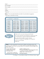
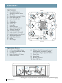
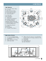
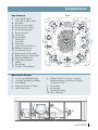
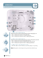
1
s a r a t o g a s p a®
Owner’s Manual
Luxury Edition
Model: __________________________________________________________
Serial Number: ___________________________________________________
Date Installed: ____________________________________________________
Dealer: __________________________________________________________
Address: _________________________________________________________
Telephone: _______________________________________________________
Note: The serial number/identification label is located within the equipment
compartment and skimmer housing.
LU XURY SERIES
M O D EL
A V G . F I LL
A V G . F I LL WE I G H T
A V G . D R Y WE I G H T
Adelphi
240 gal. / 909 L
2504 lbs. / 1136 kg.
500 lbs. / 227 kg.
Putnam
340 gal. / 1287 L
3457 lbs. / 1568 kg.
620 lbs. / 281 kg.
Canfield
375 gal. / 1420 L
3880 lbs. / 1760 kg.
750 lbs. / 340 kg.
Regent*
425 gal. / 1609 L
4297 lbs. / 1949 kg.
750 lbs. / 340 kg.
Lincoln
525 gal. / 1988 L
5302 lbs. / 2405 kg.
920 lbs. / 417 kg.
Empire
525 gal. / 1988 L
5302 lbs. / 2405 kg.
920 lbs. / 417 kg.
Broadway
795 gal. / 3010 L
7835 lbs. / 3554 kg. 1200 lbs. / 544 kg.
Thank you for your recent Saratoga Spa® Purchase.
This owners manual has been designed to acquaint you with
your Saratoga Spa’s® operation and general maintenance.
Keep this manual available for future reference.
If you have any questions regarding your Saratoga Spa®,
contact your local dealer.
Thank you.
Note: If you have purchased a Luxury Line ES Model, the following features will
not be part of the Standard ES versions. Please make note of this when referring to your
owner’s manual. Note that most operational aspects of your Luxury Line ES model will be unaffected by these changes.
• Designer Shell Vinyl Trim
• Stainless Steel Jet Accents
• Jet Pump 3 on the:
Lincoln, Empire and Broadway
• Slide Rail System on the Spa base
• Ambiance Lighting System
• Roto Stream® Automated Sequencing System on the:
Canfield, Lincoln, Empire and Broadway
• Whisper Zone™ Ozone Generator
• Full Foam Insulation
* The Regent is a Special Edition Model. Not all Luxury features apply.
Tab le of Conte n ts
Saratoga Spa® S A F E T Y Ins tru c ti ons
Avoiding Risk to Children . . . . . . . . . . . . . . . . . . . .
Avoiding Risk of Electrical Shock . . . . . . . . . . . . . . .
Avoiding Risk of Injury . . . . . . . . . . . . . . . . . . . . . .
Unclean Water . . . . . . . . . . . . . . . . . . . . . . . . . . . . .
Avoiding Risk of Hyperthermia . . . . . . . . . . . . . . . .
Avoiding Risk of Skin Burns . . . . . . . . . . . . . . . . . .
Important Do's and Don'ts . . . . . . . . . . . . . . . . . . .
2
2
3
3
4
4
5
Luxury Line Spa Model SPECIFICATIONS
Specifications . . . . . . . . . . . . . . . . . . . . . . . . . . . . . 6
Luxu ry Lin e Featu res
and Oper ation s
Adelphi . . . . . . . . . . . . . . . . . . . . . . . . . . . . . . . . . . 7
Putnam . . . . . . . . . . . . . . . . . . . . . . . . . . . . . . . . . . 8
Canfield . . . . . . . . . . . . . . . . . . . . . . . . . . . . . . . . . . 9
Regent . . . . . . . . . . . . . . . . . . . . . . . . . . . . . . . . . . 10
Lincoln . . . . . . . . . . . . . . . . . . . . . . . . . . . . . . . . . 11
Empire . . . . . . . . . . . . . . . . . . . . . . . . . . . . . . . . . 12
Broadway . . . . . . . . . . . . . . . . . . . . . . . . . . . . . . . 13
E q u i p me n t M a i n t e na n ce
Jet Valve Maintenance . . . . . . . . . . . . . . . . . . . . . . 36
Roto Stream™ Valve Maintenance . . . . . . . . . 36-37
LED Light Bulb Replacement . . . . . . . . . . . . . . . . 37
Con t r o l Pa n el F UNCTI ON S
Main Control Panel . . . . . . . . . . . . . . . . . . . . . . . . 38
Main Control Panel Buttons
and Digital Display . . . . . . . . . . . . . . . . . . . . . . . . 38
Temperature Control . . . . . . . . . . . . . . . . . . . 38
Operating the Hydro Pumps . . . . . . . . . . . . . 39
Jet Buttons . . . . . . . . . . . . . . . . . . . . . . . . . . . 39
Light Control/Ambiance Lighting System . . .40
Optional Luxury Splash™ Lighting . . . . . . . .40
Optional Luxury Sound Systems . . . . . . . . . . 40
Heating Modes . . . . . . . . . . . . . . . . . . . . . . . . . . . .40
Filter Cycle Modes . . . . . . . . . . . . . . . . . . . . . . 40-41
Freeze Protection . . . . . . . . . . . . . . . . . . . . . . . . . 41
Summer Set Mode . . . . . . . . . . . . . . . . . . . . . . . . . 41
Automated Purge Cycle . . . . . . . . . . . . . . . . . . . . . 41
Satellite Panel . . . . . . . . . . . . . . . . . . . . . . . . . . . . . 41
Insta llation I ns tru c ti ons
Location Preparation . . . . . . . . . . . . . . . . . . . . . . . 14
Outdoor Installation . . . . . . . . . . . . . . . . . . . . . . . 14
Indoor Installation . . . . . . . . . . . . . . . . . . . . . . . . 14
Ele ctr ical Requ i rements
and Pr ecautions
220 V Permanently Connected Models . . . . . . . . . 15
Electrical Installation Instructions . . . . . . . . . . 15–16
Electrical Spa Wiring Connection Instructions . . . 16
Initial Operating Instructions
Start-up and Refill Procedures . . . . . . . . . . . . . . . . 17
Start-up Procedures . . . . . . . . . . . . . . . . . . . . . 18-19
Saratoga Spa® Jet Identifications . . . . . . . . . . . 20-21
Saratoga Spa® Jet Selectors . . . . . . . . . . . . . . . . . . 22
Jet System Men u s
Jet Therapy Zones . . . . . . . . . . . . . . . . . . . . . . . . . 23
Adelphi . . . . . . . . . . . . . . . . . . . . . . . . . . . . . . . . . 24
Putnam . . . . . . . . . . . . . . . . . . . . . . . . . . . . . . . . . 25
Canfield . . . . . . . . . . . . . . . . . . . . . . . . . . . . . . 26-27
Regent . . . . . . . . . . . . . . . . . . . . . . . . . . . . . . . 28-29
Lincoln . . . . . . . . . . . . . . . . . . . . . . . . . . . . . . 30-31
Empire . . . . . . . . . . . . . . . . . . . . . . . . . . . . . . 32-33
Broadway . . . . . . . . . . . . . . . . . . . . . . . . . . . . 34-35
S pa C a r e a n d Wat e r M a i n t e na n ce
General Information . . . . . . . . . . . . . . . . . . . . 41-42
Filter Cartridge Removal and Cleaning . . . . . . 42-43
Care of Pillows . . . . . . . . . . . . . . . . . . . . . . . . . . . 43
Care of Exterior . . . . . . . . . . . . . . . . . . . . . . . . 43-44
Care of Spa Cover . . . . . . . . . . . . . . . . . . . . . . . . . 44
Winterizing Your Spa . . . . . . . . . . . . . . . . . . . 44-45
Water Quality Maintenance . . . . . . . . . . . . . . 46-48
Ozone Generators . . . . . . . . . . . . . . . . . . . . . . . . . 48
T r o u bles h o ot i n g
Operations Trouble Shooting Guide . . . . . . . . 49-50
Diagnostic Display Messages . . . . . . . . . . . . . . . . . 51
S E RVI C E AND WARRANT Y I N F OR M AT I ON
Delivery and Moving Instructions . . . . . . . . . . . . . 52
Service and Warranty Information . . . . . . . . . . . . 53
Spa Care and Maintenance Record . . . . . . . . . 54-56
S ARATOGA SPA ® S AFETY INSTRUCTION S
Read And Follow All Instructions
AVOIDING THE RISK TO CH ILDREN
Risk of Child Drow ni ng
Extreme caution must be exercised to prevent unauthorized access by children. To avoid
accidents, ensure that children cannot use a spa unless they are supervised at all times.
!
!
!
!
• To reduce the risk of injury, do not permit children to use this spa unless they are closely
supervised at all times.
• To reduce the risk of injury, lower water temperatures and control the time of hot water
exposure for young children. Children are especially sensitive to hot water.
Risk o f Ele c tro c u ti on
• Connect only to a grounded source.
• Do not bury the power cord. A buried power cord may result in death, or serious
personal injury due to electrocution if direct burial-type cable is not used, or if
improper digging occurs.
• A ground terminal (pressure wire connector) is provided on the control box inside the
unit to permit connection of a minimum No. 8 AWG (8.4 mm) solid copper bonding
conductor between this point and any metal equipment, metal water pipe, metal
enclosures
of electrical equipment, or conduit within five feet (1.5 m) of the unit as needed to
comply with local requirements.
• To reduce the risk of electrocution, replace all damaged cords immediately. Failure to
do so may result in death or serious personal injury due to electrocution.
• Do not connect any auxiliary components (for example, additional cable speakers,
headphones or other audio components) to the audio system unless approved by
Saratoga Spa® Company.
• Do not self-service audio components by opening or removing the cover as this may
expose you to dangerous voltage or other risk of injury. Only qualified service personal
should service your spa and it's components.
!
!
2
• Do not attach an external antenna to a spa audio system unless it is installed by a
licensed electrician in accordance with Article 810 of the National Electric Code,
ANSI/NFPA 70.
AVOIDING risk of electrical shock
• Do not permit any electrical appliance, such as a light, telephone, radio or television
within 5 feet (1.5m) of a spa. These units DO NOT have an internal ground fault
circuit interrupter. The installation of a ground fault circuit interrupter MUST be
done by a qualified Electrician and must meet all local and national codes. Failure
to maintain a safe distance may result in death, or serious personal injury due to
electrocution, if the appliance should fall into the spa.
S a r ato g a Spa ®
OWNER 'S M A N UA L
• Install at least 5 feet (1.5 m) from all metal surfaces. A spa may be installed within 5 feet
of a metal surface if each metal surface is permanently connected by a minimum No. 8
AWG (8.4 mm) solid copper conductor attached to the wire ground connector on the
terminal box that is provided for this purpose if in accordance with National Electrical
Code ANSI/NMFPA70-1993.
!
• Install your spa in such a way that drainage is away from the electrical compartment
and from all electrical components.
!
AVOIDING RISK OF INJURY
• To reduce the risk of injury to persons, DO NOT remove suction fittings located at
the bottom footwell of the spa.
• The suction fittings in the spa are sized to match the specific water flow created by the
pump. Never replace a suction fitting with one rated less than the flow rate marked on
the original suction fitting. Never operate the spa if the suction fittings are broken or
missing.
• There is a danger of slipping and falling. Remember that wet surfaces can be very
slippery. Take care when entering or exiting the spa.
• People with infectious diseases should not use the spa.
• Keep any loose articles of clothing or hanging jewelry away from rotating jets or other
moving components.
• The use of drugs, alcohol, or medication before or during spa use may lead to
unconsciousness with the possibility of drowning.
• Persons using medications should consult a physician before using a spa; some medication
may cause a user to become drowsy, while other medication may affect heart rate, blood
pressure, and circulation.
• Persons taking medications which induce drowsiness, such as tranquilizers,
antihistamines or anticoagulants should not use the spa.
• Water temperature in excess of 104ºF (38ºC) may be injurious to your health.
• Pregnant women should consult a physician before using spa.
• Persons suffering from obesity, or with a medical history of heart disease, low or high
blood pressure, circulatory system problems, or diabetes should consult a physician
before using spa.
• Persons using or having Implanted Pacemakers or Defibrillators should consult their
physician prior to using a spa, as there are risks of electrocution.
Unclean Water
• Keep the water clean and sanitized with correct chemical care.
• Maintain water chemistry in accordance with chemical manufacturer’s instructions.
Important:
• Turn the Jet Pump on high speed after adding ANY spa water chemicals into the spa. It will
operate for a 15 minute cycle before shutting off automatically.
•Clean the filter cartridges monthly to remove debris and mineral buildup which may affect the performance of the jets, limit the flow, or cause a high limit problem.
S ar at oga S p a ®
OWN E R' S M AN UAL
3
!
!
AVOIDING RISK OF HYPerTH ERMIA
The causes, symptoms and effects of hyperthermia may be described as follows:
Hyperthermia occurs when the internal temperature of the body reaches a level several
degrees above the normal body temperature of 98.6ºF. The symptoms of hyperthermia
include an increase in the internal temperature of the body, dizziness, lethargy,
drowsiness and fainting.
The effects of hyperthermia include:
1. Failure to perceive heat.
2. Failure to recognize the need to exit the spa or hot tub.
3. Unawareness of impending hazard.
4. Fetal damage in pregnant women.
!
5. Physical inability to exit the spa or hot tub.
!!
The use of alcohol, drugs, or medication can greatly increase the risk of fatal
hyperthermia in hot tubs and spas.
!
To Reduce The Risk of Injury:
6. Unconsciousness resulting in drowning.
• The water in the spa should never exceed 104°F (40ºC). Water temperatures
between 100°F (37.7ºC) and 104°F (40ºC) are considered safe for a healthy adult.
• Lower water temperatures are recommended for extended use (exceeding ten
minutes) and for young children. Extended use can cause hyperthermia.
!
!
• Pregnant or possibly pregnant women should consult with their physician before
entering a spa. Failure to do so may result in permanent injury to your baby.
• Do not use spa immediately following strenuous exercise.
AVOIDING RISK OF SKIN BURNS
• To reduce the risk of injury, before entering a spa the user should measure the
water temperature with an accurate thermometer, since the tolerance of temperatureregulating devices may vary by as much as ±5°F.
• Test the water with your hand before entering the spa to be sure it’s comfortable.
4
S a r ato g a Spa ®
OWNER 'S M A N UA L
Important:
The following contains important spa information, and we strongly encourage you to read
and apply them.
!
!
!
!
IMPORTANT DO 'S & DON'TS
Do:
• Make sure you always lock the child resistant spa cover locks after using the spa for
your children’s safety. Every Saratoga Spa® is equipped with a locking cover that meets
the ASTM F1346-91 Standard for Safety Covers.
• Test the water temperature with your hand before allowing people to enter the spa to
be sure that it’s comfortable. Remember, children are especially sensitive to hot water.
• Remind children that wet surfaces can be very slippery. Make sure that children are
careful when entering or exiting the spa.
• Use and lock the vinyl cover when the spa is not in use, whether it is empty or full.
• Follow the Spa Care and Maintenance recommendations stated in this manual.
• Use only approved accessories and recommended spa chemicals and cleaners.
• Keep the spa cover locked when the spa is not in use.
• Check the equipment compartment monthly for any signs of tampering to the spa
equipment.
• Follow the maintenance instructions of the spa found in this owner’s manual.
• Be sure your spa is connected to the power supply correctly - use a licensed
electrical contractor.
• Test the Ground Fault Circuit Interrupter(s) once a month.
• Place the spa on a level load bearing surface.
Don't:
• Allow children to climb onto the spa cover.
• Allow children to have unsupervised access to the spa.
• Leave the Saratoga Spa® exposed to the sun without water or the cover in place.
Exposure to direct sunlight can cause solar distress of the shell material.
• Lift or drag the vinyl cover by using the cover lock straps; always lift or carry the cover
by using the handles.
• Attempt to open the electrical control box. There are no user serviceable parts inside.
Opening of the control box by the spa owner will void the warranty. If you have an
operational problem, carefully go through the steps outlined in the Troubleshooting
section. If you are not able to resolve the problem, contact your authorized Saratoga
Spa® dealer. Many problems can easily be diagnosed over the telephone by an
Authorized Service Technician.
• Block or sit on the filter compartment area.
• Allow excessive weight to be placed on the spa cover. Doing so could damage the spa
cover and void any warranty.
• Use the spa with the equipment compartment door removed.
• Place electrical appliances within 5 feet (1.5m) of the spa.
• Block the equipment compartment vents. This could cause damage to the spa
equipment and will void the warranty.
* S a ve T h ese I n s t r u c t i o n s *
S ar at oga S p a ®
OWN E R' S M AN UAL
5
S PA S P E C IF ICAT IONS
Width
Length Height
Average
Fill
Dry Weight
Average
Seating Fill Weight Locations
Adelphi
67”
1.70 m
80”
2.03 m
29”
0.74 m
240 gal
909 L
500 lbs.
227 kg
2,504 lbs.
1,136 kg
2–3
Putnam
75”
1.91 m
84”
2.13 m
36”
0.91 m
340 gal
1,287 L
620 lbs.
281 kg
3,457 lbs.
1,568 kg
4–5
Canfield
84”
2.13m
84”
2.13 m
38”
0.97 m
375 gal
1,420 L
750 lbs.
340 kg
3,880 lbs.
1,760 kg
5–6
Regent
84”
2.13 m
90”
2.29 m
38”
0.97 m
425 gal
1609 L
750 lbs.
340 kg
4,297 lbs.
1,949 kg
5–6
Lincoln
90”
2.29 m
94”
2.39 m
40”
1.02 m
525 gal
1988 L
920 lbs.
417 kg
5,302 lbs.
2,405 kg
6–7
Empire
89”
2.26 m
93”
2.36 m
40”
1.02m
525 gal
1988 L
920 lbs.
417 kg
5,302 lbs.
2,405 kg
6–7
Broadway
92”
2.34 m
108”
2.74 m
40”
1.02 m
795 gal
3010 L
1200 lbs.
544 kg
7,835 lbs.
3,554 kg
9
!
!
Due to the risk of property damage and injury, the manufacturer of the Saratoga Spa®
strongly suggests a structural engineer or licensed contractor be consulted before the spa
is placed on an elevated deck.
Note: The “Average Full” weight of the spa includes only the spa and the water inside the spa.
6
S a r ato g a Spa ®
OWNER 'S M A N UA L
Ad elph i
Spa Features
k
B
CO
O
f
E
F
j
N
M
F
I
g
D
D
E
E
RIGHT
H
LEFT
A. Versa-Flo™ Micro Valves
B. Air Valves
C. Power Massage® Jets
D. Power Stream® Jets
E. Cluster Jets
F. Standard Jets
G. Storm Jets
H. Vortex Jet™ Circulation
I. Whisper Clean® Jet
J. Footwell Spa Drain
K. Relax Stream™ Waterfall
L. Backlit Digital Control Panel
M. Microban® Filtration
N. Toploading Skimmer
O. Pillows
P. Mood Light
REAR
a
F
P
b
L
O
C
a
F RO N T
Operations Center
1.
2.
3.
4.
5.
6.
7.
8.
9.
(1) Two Speed Hydro Pump
4 kW Heater
Purity Circulation™ Pump
220V Power Pack
Whisper Zone™ Ozonator- Located behind
the 220V Power Pack (Standard on XL)
Drain Valve
Mood Light
Bonding Terminal
Shut-Off Valves
7
9
9
1
6
9
8
4
5
2
3
9
S ar at oga S p a ®
OWN E R' S M AN UAL
7
Pu t na m
Spa Features
REAR
A. Versa-Flo™ Micro Valves
B. Air Valves
C. Power Massage® Jets
D. Power Stream® Jets
E. Cluster Jets
F. Standard Jets
G. Deluxe Jets
H. Storm Jets
I. Vortex Jet™ Circulation
J. Whisper Clean® Jet
K. Footwell Spa Drain
L. Relax Stream™ Waterfall
M. Backlit Digital Control Panel
N. Microban® Filtration
O. Toploading Skimmer
P. Pillows
Q. Mood Light
C
A
P
B
E
E
P
G
G
E
I
LEFT
K
J
G
E
P
RIGHT
D
h
D
N
O
E
G
F
Q
M
B
A
C
P
F RO N T
Operations Center
1.
2.
3.
4.
5.
6. Whisper Zone™ Ozonator- Located behind the
(1) Two Speed Hydro Pump
(1) Single Speed Hydro Pump
4 kW Heater
Purity Circulation™ Pump
220V Power Pack
Purity Circulation™ Pump (Standard on XL)
7. Drain Valve
8. Mood Light
9. Bonding Terminal
10.Shut- Off Valves
8
10
10
10
1
7
8
S a r ato g a Spa ®
OWNER 'S M A N UA L
3
9
4
6
5
10
10
10
2
Ca nfield
Spa Features
A. Versa-Flo™ Valves/
REAR
Q
i
g
i
g
p
O
LEFT
M
A R
g
k
L
j
e
i
a
N
b
I
e
C
d
i
e
e
e
Q
a
g
gf
Q
g
b
h
RIGHT
Versa-Flo™ Micro Valves
B. Air Valves
C. Mood Light
D. Power Massage® Jets
E. Power Stream® Jets
F. Whisper Clean® Jet
G. Cluster Jets
H. Standard Jets
I. Deluxe Jets
J. Storm Jets
K. Vortex Jet™ Circulation
L. Footwell Spa Drain
M. Relax Stream™ Waterfall
N. Backlit Digital Control Panel
O. Microban® Filtration
P. Toploading Skimmer
Q. Pillows
R. Roto Stream™ Valves
Q
d
a
F RO N T
Operations Center
1.
2.
3.
4.
5.
6. Whisper Zone™ Ozonator- Located behind the
(1) Two Speed Hydro Pump
(1) Single Speed Hydro Pump
4 kW Heater
Purity Circulation™ Pump
220V Power Pack
Purity Circulation™ Pump (Standard on XL)
7. Drain Valve
8. Mood Light
9. Bonding Terminal
10.Shut- Off Valves
8
10
1
10
10
3 9
5
4
10
10
6
10
2
7
S ar at oga S p a ®
OWN E R' S M AN UAL
9
Reg e n t *
Spa Features
REAR
N
a
DR
Versa-Flo™ Micro Valves
B. Air Valves
C. Manual Roto Stream™ Valve
D. Power Massage® Jets
E. Power Stream® Jets
F. Cluster Jets
G. Standard Jets
H. Deluxe Jets
I. Storm Jets
J. Master Massage
K. Vortex Jet™ Circulation
L. Whisper Clean® Jet
M. Footwell Spa Drain
N. Relax Stream™ Waterfall
O. Backlit Digital Control Panel
P. Microban® Filtration
Q. Toploading Skimmer
R. Pillows
S. Mood Light
H
LEFT
M
Y
R
R
H
F
a
C
b
F
Hi
c
F
H
F
F
CM
MY
K
L M
J
CY
RIGHT
A. Versa-Flo™ Valves/
CMY
G
E
R
G
D
H
K
S
a
b
P
Q
O
F RO N T
Operations Center
1.
2.
3.
4.
5.
6. Whisper Zone™ Ozonator- Located
(1) Two Speed Hydro Pump
(1) Single Speed Hydro Pump
4 kW Heater
Purity Circulation™ Pump
220V Power Pack
10
10
1
7
10
behind Purity Circulation™ Pump
(Standard on Regent Special Edition)
7. Drain Valve
8. Mood Light
9. Bonding Terminal
10.Shut- Off Valves
3
9
4
5
6
8
10
10
10
2
* The Regent is a Special Edition model. Not all Luxury features apply.
10
S a r ato g a Spa ®
OWNER 'S M A N UA L
Linco ln
Spa Features
REAR
S m
h
i
q
i
i
h
b
g
g
g g
i
g g
h
c
a
g
l k
F
a
g g
g
H
r
i
e
F
d
o
p
q
q i
e
j
RIGHT
h
q
LEFT
A. Versa-Flo™ Micro Valves
B. Air Valves
C. Roto Stream™ Valves
D. ProJet Stream™ Valves
E. Power Massage® Jets
F. ProJet Stream™
G. Cluster Jets
H. Standard Jets
I. Deluxe Jets
J. Vortex Jet™ Circulation
K. Whisper Clean® Jet
L. Footwell Spa Drain
M. Relax Stream™ Waterfall
N. Backlit Digital Control Panel
O. Microban® Filtration
P. Toploading Skimmer
Q. Pillows
R. Mood Light
S. Satellite Control Button
n b
a
F RO N T
Operations Center
1.
2.
3.
4.
5.
6. Whisper Zone™ Ozonator- Located behind
(1) Two Speed Hydro Pump
(2) Single Speed Hydro Pumps
4 kW Heater
Purity Circulation™ Pump
220V Power Pack
3
10 10
10
1
Purity Circulation™ Pump (Standard on XL)
7. Drain Valve
8. Mood Light
9. Bonding Terminal
10.Shut- Off Valves
9
5
2
4
7
8
10
10 10
10
10
2
6
S ar at oga S p a ®
OWN E R' S M AN UAL
11
Em pi r e
Spa Features
A. Versa-Flo™ Valves/
REAR
P
a c A
e
t
V
j
j
a
g
LEFT
g
i
no
k
t
a b
j
i
h
t
h
g
r
s
F
m
f
L
f
g
j i
f
f
u
t
e
g
b a d
q
F RO N T
Operations Center
1.
2.
3.
4.
5.
6. Whisper Zone™ Ozonator- Located behind the
(1) Two Speed Hydro Pump
(2) Single Speed Hydro Pumps
4 kW Heater
Purity Circulation™ Pump
220V Power Pack
Purity Circulation™ Pump (Standard on XL)
7. Drain Valve
8. Mood Light
9. Bonding Terminal
10.Shut- Off Valves
8
10
1
S a r ato g a Spa ®
OWNER 'S M A N UA L
9
5
10
2
4
7
12
3
10
6
10
10
10
10
10
2
RIGHT
Versa-Flo™ Micro Valves
B. Air Valves
C. Roto Stream™ Valves
D. ProJet Stream™ Valves
E. Power Massage® Jets
F. Power Stream® Jets
G. ProJet Stream™
H. Cluster Jets
I. Standard Jets
J. Deluxe Jets
K. Storm Jets
L. Master Massage
M. Vortex Jet™ Circulation
N. Whisper Clean® Jet
O. Footwell Spa Drain
P. Relax Stream™ Waterfall
Q. Backlit Digital Control Panel
R. Microban® Filtration
S. Toploading Skimmer
T. Pillows
U. Mood Light
V. Satellite Control Button
Br oa d way
Spa Features
REAR
A. Versa-Flo™ Valves/
4/13/12
1
g
g
g
i
h
m
N g
i
j
h
i
h o
s
f
c A
s
b A
t
i
j
s
o
p
h
g
ig
g
u
o
s h
A
g
g
h
b
A
h
RIGHT
LEFT
o
s
g
g
S
Broadway12.pdf
A
g
l
S
i
qr
k
E
ES
e
3:58 PM
Versa-Flo™ Micro Valves
B. Air Valves
C. Roto Stream™ Valves
D. ProJet Stream™ Valves
E. Power Massage® Jets
F. ProJet Stream™
G. Cluster Jets
H. Standard Jets
I. Deluxe Jets
J. Storm Jets
K. Turbo Jets
L. Vortex Jet™ Circulation
M. Whisper Clean® Jet
N. Footwell Spa Drain
O. Relax Stream™ Waterfall
P. Backlit Digital Control Panel
Q. Microban® Filtration
R. Toploading Skimmer
S. Pillows
T. Mood Light
U. Satellite Control Button
A
d
f
ES
F RO N T
Operations Center
1.8/18/10
(1) Two
Speed Hydro Pump
8:59:32 AM
2. (2) Single Speed Hydro Pumps
3. 4 kW Heater
4. Purity Circulation™ Pump
5. 220V Power Pack
10
1
10
K
CY
CMY
MY
Y
CM
behind the Purity Circulation™ Pump
(Standard on XL)
7. Drain Valve
8. Mood Light
9. Bonding Terminal
10.Shut- Off Valves
3
10
10
M
C
6. Whisper Zone™ Ozonator- Located
Broadway10.pdf
8
9
5
2
7
10
10
10
2
4
6
S ar at oga S p a ®
OWN E R' S M AN UAL
13
I N STA L LAT I ON INS TRUCTIONS
Location Preparation
Your Saratoga Spa® is totally self-contained and portable. You can install the spa outside or
inside. Preferable places are on a patio, deck or indoors. The spa should always be placed on a
structurally strong, level surface. Other items you need to consider are the following:
• Verify that the location chosen can support the weight of the spa, the water of the spa and
its occupants.
• Always check the surface of the site to see if it is level before filling the spa with water.
• Allow access to the equipment compartment for routine maintenance.
• Do not block the air vents found on the face of the equipment compartment.
• When positioning the spa, be sure to allow for drainage away from the electrical compartment.
• Leave easy access to the GFCI breaker.
• See page 52 for delivery and moving instructions.
!
!
The Saratoga Spa® is manufactured to be a portable unit. Any permanent installation of
this product is done at the risk of the owner. Permanent installation of this unit violates
warranty coverage.
Outdoor Installation
Always keep in mind what type of climate you live in. In a climate with cold, snowy winters you
may want to consider locating the spa close to the house for easy access. In climates where it is
normally warm or hot year-round, it would be recommended to place the spa in a shaded or cool
area. With deck installations it is recommended that a qualified building contractor or structural
engineer review the weight the deck can support. The spa specification sheet (on page 6) can
assist you with the weights and dimensions of your spa.
Indoor Installation
Special requirements are needed for indoor installation. Spas normally produce moisture. A
ventilation system needs to be considered. Your spa area should contain moisture resistant wall/
floor coverings and building materials to avoid damage from moisture over time. Proper drainage
of the spa water also needs to be considered.
!
!
Your Saratoga Spa® is equipped with air vents to allow for circulation of air throughout
the equipment compartment. These vents are found on the face of the equipment
compartment panel and under the corners of the spa at the equipment compartment
end. Do not allow vents to be blocked as to prevent the circulation of air in the
equipment compartment.
Your Saratoga Spa® dealer can help you with information such as local
zoning regulations and building codes.
14
S a r ato g a Spa ®
OWNER 'S M A N UA L
ELE CTR I CAL REQUIREMENTS AND PR ECAUTION S
Your Saratoga Spa® has gone through numerous tests to verify that all of the spa functions
operate. Beyond the tests, your Saratoga Spa® has been designed to provide the maximum safety
against electrical shock. Read and follow the electrical installation requirements and instructions
completely. The next few pages will assist you in properly connecting the electrical input. Follow
the electrical instructions for your specific spa model. Serious risks or injuries may occur if the
spa is improperly wired.
!
!
220 Volt Permanently Connected Models:
-Adelphi-Putnam
-Canfield
-Lincoln-Empire
-Broadway
-Regent
Saratoga Spa® models must be wired in accordance with all applicable local electrical
codes. Use NEC 250-122(table) and local codes for more information. All electrical
work should be done by an experienced, licensed Electrician. We recommend the use of
appropriate electrical conduit, fittings and wire for all circuits.
220 Volt installations require a 60Hz, single phase, three-wire electrical service plus
ground (Line 1, Line 2, Neutral and Ground) and must be connected using a minimum
supply conductor ampacity of 50 AMPs and a minimum circuit breaker size of 50 AMPs.
Note: Use copper wire only (3 wire with ground; 8 gauge under 50', 6 gauge over 50')
220 Volt model spas must be connected to a “dedicated” 220 volt 50 Amp grounded
circuit. The term “dedicated” means the electrical circuit is not being used for any other
electrical items (lights, appliances, etc.). If the spa is connected to a non-dedicated
circuit, overloading will occur and nuisance tripping of the GFCI breaker switch at the
house breaker panel will occur.
!
!
A ground lug connector is provided on the exterior surface of the spa pack (operations
center) inside the equipment compartment. This is to permit the connection of a
bonding wire between this point and any metal equipment, enclosures, pipe or conduit
within five feet (1.5m) of the spa. This bonding wire must be at least 8AWG solid
copper wire.
Due to the risk of equipment damage or fire, use only approved pressure-type wire
splicing lugs or connectors suitable for the size and type of wiring used.
Electrical Installation Instructions for 220 Volt Models
1.To connect the electrical service, first remove the screws from the equipment compartment door. Carefully remove the access panel.
2. Locate the spa power pack. Loosen the screws on the front of the control box. Remove the
screws and the control box cover.
3. Input the electrical service from the GFCI breaker into the spa equipment compartment.
!
!
The GFCI breaker must be placed in sight of the spa, at a minimum distance of five feet
(1.5m) away.
As of January 1, 1996 the National Electric Code (NEC) requires GFCI (Ground Fault
Circuit Interrupter) on all spa installations.
4. Connect the supply conduit to the spa power pack.
S ar at oga S p a ®
OWN E R' S M AN UAL
15
B otto m V iew
o f B r e ake r
Factory
Installed
Neutral
(Pigtail)
Power to Spa
Neutral to Spa
Incoming
Ground (Green)
Incoming
Power (Black)
Ground to Spa
Outgoing Power to Spa
Outgoing Neutral to Spa
Incoming Power (Black or Red)
Incoming Neutral (White)
!
Electrical Spa Wiring Connection Instructions
!
Due to the risk of damaging the PC Board, the equipment and the GFCI tripping,
never, under any circumstances, should you connect power to the neutral terminal.
1. Identify the TB-1 terminal block, located inside the spa power pack on the left side.
2. Connect the 8 AWG, BLACK wire, from the GFCI 50 amp breaker, terminal L1 to
TB-1, Line 1.
3.Connect the 8 AWG, WHITE wire, from the GFCI 50 amp breaker, terminal N to
TB-1, neutral.
4. Connect the 8 AWG, GROUND wire, from the GFCI 50 amp breaker, terminal GND
(ground) to TB-1, ground.
5. Connect the 8 AWG, RED wire, from the GFCI 50 amp breaker, terminal L2 to
TB-1, Line 2.
6. At least two additional lugs marked “Bonding Lugs” are provided on the external surface
of one of the bonded components metal enclosures. To reduce the risk of electrical shock,
connect the local common bonding grid in the area of the hot tub or spa to these terminals
with an insulated or bare copper conductor not smaller than No. 6 AWG.
7.All field-installed metal components such as rail, ladders, drains or other similar hardware
within 10 ft. (3m) of the spa or hot tub shall be bonded to the equipment grounding bus with
copper conductors not smaller than No. 6 AWG.
8. Replace the control box cover and securely tighten the fastening screws. Close and secure the
equipment compartment panel.
!
!
Always use copper wire only (3 wire with ground. 8 gauge under 50 ft., 6 gauge over
50 ft.)The electrical supply for this product must include a suitable rated switch or
circuit breaker to open all ungrounded supply conductors to comply with Section
422.20 of the National Electrical Code ANSI/NEPA 70-1987. The disconnecting
means must be readily accessible to the tub occupant but installed at least 5 feet
(1.5m) from tub water
!
Please review the back of the spa pack cover, located in the spa equipment bay, for
a complete spa equipment wiring diagram. Always use a licensed Electrician when
wiring the spa.
!
16
S a r ato g a Spa ®
OWNER 'S M A N UA L
I N I T I A L OPERAT ING INS TRUCTION S
Start-Up and Refill Procedures
Your Saratoga Spa® has been tested at the manufacturing plant to ensure that all of the spa
functions operate. During the test procedure, a small amount of water may have remained in
the spa plumbing. Through the shipping process water may have spotted the spa shell. You may
need to wipe down the shell with a soft cloth. Please read and follow the start-up instructions to
ensure a successful start-up or refill.
!
!
• Inspect and clean spa shell of any debris
• Do not turn power on to spa unless filled with water to appropriate level (See Page
18). The spa pack must never be operated without water in the spa; serious damage to
the heater and/or pump(s) may result.
• Do not fill spa with water before checking the items below (below items may become
loose in transit):
A
A. Hand tighten unions at the pumps
B. T
ighten drain valve
A
Note: Drain Valve is left open for shipping;
drain valve must be closed before filling spa.
C. Tighten unions on heater
B
C
C
• Do not fill spa with hot water. This may cause a false error code to the temperature sensors.
S ar at oga S p a ®
OWN E R' S M AN UAL
17
Start-up Procedures
1. For a successful start-up, fill the spa with water through the Whisper Clean® cartridge.
The Whisper Clean® cartridge is the cartridge with the coarse threaded yellow ACME
style adapter.
a. Locate the filter compartment area.
b. Pull up and remove filter cover.
c. Remove the filter cartridge and screen adapter by turning them counter clockwise.
d. After removing each filter cartridge and screen adapter, place a garden hose through the
filter opening.
e. Turn water on and run water until it reaches a minimum level of 2” above the top of the filters.
Note: Besides filling the spa to 2” above the top of the filter, all models will need to be
filled to 2” above the highest jet(s) in the spa. This is the minimum level allowed to run
the Whisper Clean® circulation system.
Note: When using a mineral cartridge system, please refer to your dealer for specific
instructions on installation.
2. Check all plumbing (clamps, unions and drain valve) connections for leaks.
3. Re-install filter cartridges and screen adapters by turning them clockwise. Exit garden hose
from the spa.
4. At this point, turn on the spa control system by turning on the GFCI breaker. When your
spa is first actuated, it will go into Priming Mode, indicated by "Pr". During this mode the
heater is disabled to allow the priming process to be completed. As soon as "Pr" is indicated
on the topside panel, push the Jet(s) button(s) until the pump(s) are running in high speed.
If the pump(s) have been primed continue to step 5. If the pump(s) have not primed after 2
minutes, and water is not flowing from the jets in the spa it may be nessessary to manually
prime the pump(s) by taking the following steps: First turn the power off on the GFCI
breaker. Next loosen the union nuts on the pump(s). Allow for a small amount of water and
the trapped air to escape from the pump(s). Once all the air has escaped tighten the union
nuts back down. After the pump(s) have been vented, turn on the spa control system by
turning on the GFCI breaker. The spa will now go back into priming mode.
18
S a r ato g a Spa ®
OWNER 'S M A N UA L
5. After the pumps are primed turn off by pressing the Jet(s) button(s). Next manually exit
the priming mode by pressing either the Warm or Cool button. After you have manually
exited the priming mode the display will show the set temperature, which defaults at
100° F/ 37°C, followed by two dashes (--). This will last for two minutes while the water
temperature is determined. Push the Warm or Cool button to the desired setting.
6. Re-install filter cover and allow spa to heat to desired set temperature: this normally
takes 24 hours.
7. Water must be balanced and shocked upon start-up. See your dealer or pages 46-48 of this
manual for details. This procedure must be repeated each time the spa is drained and refilled.
8. The Whisper Clean® Jet
The combination of the Whisper Clean® and Vortex Jet™ return systems help the
Whisper Clean® System to circulate water from the surface and bottom level of the spa.
The Whisper Clean® Jet also introduces temperature controlled water and ozone into the
spas footwell area 24 hours a day. A slow or non-moving Whisper Clean® Jet may indicate
that the filter cartidges areobstructed with dirt, body oils or calcification. Follow the filter
cartridge cleaning procedures in this manual.
!
!
It is recommended to press and release the ground fault circuit interrupter (GFCI)
RESET button monthly to verify GFCI is working properly.
Important:
A pump should not be allowed to run without priming for more than 2 minutes. Under NO
circumstances should a pump be allowed to run without priming beyond the end of the 4
minutes priming mode. Doing so may cause damage to the pump and cause the system to go
into an overheat condition.
Whisper Clean® Jet
S ar at oga S p a ®
OWN E R' S M AN UAL
19
Sa r atoga S pa Jet Identifications
V er sa-Flo™ Jet s a nd C F E ™ Je t Des c ri p t i on s
Power Massage Plus® and Power Massage®*
Patented jet provides dual water massage to your neck or back from
under the built-in headrest. The jet is controlled by a small selector
valve, giving the bather total control.
* Provides a single ribbon of water flow parallel to the body
Power Stream®
Underwater jet patterned after the Power Massage®. This jet runs a
ribbon of water parallel to the surface of the spa body. Not found
in all units.
Cluster Jet & Cluster Swirl Jet
The Cluster Jet provides a concentrated stream of water
and air for precise pressure point areas. The Cluster Swirl
adds a pulsating rotation feel to the pressure point area.
Pro-Jet Stream™
Provides precise neck and shoulder massage. Retractable design is
hydro driven and allows for personalized use.
Mini Swirl Jet (Standard Jet Category)
The Mini Swirl Jet has an adjustable eyeball for directional or
rotational use. To change from directional to rotational, with finger,
simply adjust inner nozzle to the rotating position.
Mini Twin Roto Jet (Standard Jet Category)
This dual nozzle jet gives rotational intensities over focused muscle
areas.
Mini Tri-Flo Massage Jet (Standard Jet Category)
A rotating dual nozzle, diffused by three holes, creates a pulsating
body massage.
Mini Veri-Flo (Standard Jet Category)
This jet delivers a seven point pressure point flow into the muscle
area and has an interchangable design that gives relief to a variety of
areas.
Large Face Mini Swirl and Directional Jet (Standard Jet Category)
The Large Face Mini Swirl Jet has an adjustable eyeball for
directional or rotational use. To change from directional to
rotational, with finger, simply adjust inner nozzle to the rotating
position.
Note: Not all jets are available in all models
20
S a r ato g a Spa ®
OWNER 'S M A N UA L
Cyclo-Swirl Jet (Deluxe Jet Category)
A larger version of the Mini Swirl Jet, this jet gives a mid-size rotational
massage and pulsating massage. To change from
directional to rotational, with finger, simply adjust inner nozzle
to the rotating position.
Cyclo-Flo Jet (Deluxe Jet Category)
This jet provides a balanced mix of air and water to give a soft, powerful,
direct pressure massage to mid-size muscle groups. The design allows for
higher GPM for performance and maximum relief.
Dual-Flo Jet (Deluxe Jet Category)
This dual nozzle jet gives a mid-size rotational massage and pulsating
massage.
Twin-Roto Jet (Deluxe Jet Category)
The larger version of the Mini-Twin Roto Jet, this jet provides rotational
massage over a mid-size muscle areas.
Mini Gatling Jet (Deluxe Jet Category)
The smaller version of the Gatling, a rotating dual nozzle, diffused by
seven holes, creates a pulsating body massage.
Multi-Flo Jet (Deluxe Jet Category)
The smaller version of the Veri-Flo Jet, this jet delivers multiple pressure
point flow into several locations of muscle area and has an interchangeable
design that gives relief to a variety of areas.
Xtreme-Flo™ Jet (Storm Jet Category)
The Xtreme Flo jet provides a mix of water and air. The straight stream
flows from a larger nozzle for maximum relief.
Gatling Jet (Storm Jet Category)
A rotating dual nozzle, diffused by seven holes, creates a pulsating
body massage.
Veri-Flo™ Massage Jet (Storm Jet Category) & Master-Flo™ Massage Jet
Multiple pressure point flow, provides foot and large muscle relief. A
larger version of the Veri-Flo Massage Jet, the Master- Flo™ Jet delivers
multiple pressure point flow into several locations of muscle area and has
an interchangeable design that gives relief to a variety of areas.
Turbo Jet
Provides an intense lower body massage and whirlpool stimulation
through a large orifice.
Note: Not all jets are available in all models
S ar at oga S p a ®
OWN E R' S M AN UAL
21
S a r ato ga Spa Je t selec to r s
The Jets in the Saratoga Spa® Luxury Line have different
ways to adjust the jet therapy systems. While having the
Hydro Jet pump(s) on the user has the ability to turn
on and off each individual Versa-Flo™ Jet. The VersaFlo™ Jet(s) can be turned on and off by turning the
outer scallop on the face of the jet. In addition to having
the ability to control each individual jet, the jets can be
adjusted by the following zones.
Versa-Flo™ Air Control Valve
Saratoga Spa® uses six different ways to adjust the
jet therapy zones. The Roto Stream™ Valves, ProJet
Stream™ Valves, Versa-Flo™ Valves, and Versa-Flo™
Micro Valves give the user the ability to control the
different Jet Therapy Zones. The Air Control valve
controls the intensity of the Jets by opening or restricting
airflow The following pages will discuss the different jet
therapy zones found in the Luxury Line Spas.
Versa-Flo™ Valve
22
S a r ato g a Spa ®
OWNER 'S M A N UA L
Roto Stream™ Valve
Versa-Flo™ Micro Valve
Roto Stream™ Manual Valve
ProJet Stream™ Valve
Jet S YS TE M M E NU S
Jet Therapy Zones
This example will help you to understand the
following pages that discuss the jet system menus.
The navigational tool is read from standing outside
of the spa and in front of the particular selector. Keep
this in mind when the following pages discuss 12,3,6
or 9 o’clock position settings. The Versa-Flo™ Air
Control Valve and Versa-Flo™ Micro Valve can only
be rotated 180º. The Projet Stream™ Valve controls
the Projet Stream™ Jets.
Note: Luxury Spa ES models do not use the Roto Stream™ Sequencing System on
the Canfield, Lincoln, Empire and Broadway or Jet Pump 3 on the Lincoln, Empire
and Broadway.
S ar at oga S p a ®
OWN E R' S M AN UAL
23
AD E L PH I
Je t S y st e m Me nu
2A
2
2B
3
3
1
1A
1 | V E R S A - F LO ™ M ICRO VA LVE
Controls the amount of water flowing through the Power Massage® Jet 1A
• The 3 o’clock position operates a flat stream flow.
• The 9 o’clock position operates an angled stream flow.
• The 6 o’clock position operates both at a reduced performance.
2 | V E R S A - F LO ™ M ICRO VA LVE
Controls the amount of water flowing through the Power Massage® Jet 2A & 2B
• The 3 o’clock position operates a flat stream flow 2A.
• The 9 o’clock position operates the RelaxStream™ Waterfall 2B.
• The 6 o’clock position operates both at a reduced performance.
3 | V E R S A - F LO ™ A IR CONTROL VA LVE
• This Valve adds or restricts intensity to jets when pump(s) are operating.
Note: Descriptions are based upon valve operation from within the spa.
24
S a r ato g a Spa ®
OWNER 'S M A N UA L
PUTNA M
Jet S y st em Menu
2A
2
3
3
1
1A
1B
1 | V E R S A - F LO ™ M ICRO VA LVE
Controls the amount of water flowing through the Power Massage® Jet & RelaxStream™ Waterfall 1A & 1B}
• The 3 o’clock position operates a flat stream flow 1A.
• The 9 o’clock position operates the RelaxStream™ Waterfall 1B.
• The 6 o’clock position operates both at a reduced performance.
2 | V E R S A - F LO ™ M ICRO VA LVE
Controls the amount of water flowing through the Power Massage® Plus Jet 2A
• The 3 o’clock position operates an angled stream flow.
• The 9 o’clock position operates a flat stream flow.
• The 6 o’clock position operates both at a reduced performance.
3 | V E R S A - F LO ™ A IR CONTROL VA LVE
• This Valve adds or restricts intensity to jets when pump(s) are operating.
Note: Descriptions are based upon valve operation from within the spa.
S ar at oga S p a ®
OWN E R' S M AN UAL
25
CAN F I ELD
Je t S y st e m Me nu
2a
4B
2
4
4A
3a
1a
5
1
1b
3b
3
1 | V E R S A - F LO ™ M ICRO VA LVE
Controls the amount of water flowing through Jets in 1A & 1B
• The 3 o’clock position operates the RelaxStream™ Waterfall 1A.
• The 9 o’clock position operates a flat stream flow 1B. .
• The 6 o’clock position operates both at a reduced performance.
2 | V E R S A - F LO ™ M ICRO VA LVE
Controls the amount of water flowing through the Power Massage® Plus Jet 2A
• The 3 o’clock position operates an angled stream flow.
• The 9 o’clock position operates a flat stream flow
• The 6 o’clock position operates both at a reduced performance.
3 | V E R S A - F LO ™ VA LV E
Controls the amount of water flowing through Jets in 3A & 3B
• The 3 o’clock position operates the foot dome jet flow 3A.
• The 9 o’clock position operates the 12 jet seat flow 3B.
• The 6 o’clock position operates both at a reduced performance.
26
S a r ato g a Spa ®
OWNER 'S M A N UA L
*4 | roto - s tre a m ™ M ICRO VA LVE
Controls the Roto Stream™ Valves 4A sequencing speed to the 6 jets in the Roto Stream™ Seat 4B
•The 3 o’clock position turns off the Roto Stream™ valve 4A from sequencing
the six jets in seat 4B.
•The 9 o’clock position turns on the Roto Stream™ valve 4A and begins
sequencing the six jets in seat 4B.
5 | V E R S A - F LO ™ A IR CONTROL VA LVE
• This Valve adds or restricts intensity to jets when pump(s) are operating.
Note: Descriptions are based upon valve operation from within the spa.
*Not Available on ES Models
S ar at oga S p a ®
OWN E R' S M AN UAL
27
R EG E NT
Je t S y st e m Me nu
1a
3a
1
5
2a
1
3
3b
1b
5
4a
4
1 | V E R S A - F LO ™ M ICRO VA LVE
Controls the amount of water flowing through the Power Massage® Jet & RelaxStream™ Waterfall 1A & 1B
• The 3 o’clock position operates a flat stream flow 1A.
• The 9 o’clock position operates the RelaxStream™ Waterfall 1B.
• The 6 o’clock position operates both at a reduced performance.
2 | V E R S A - F LO ™ M ICRO VA LVE
Controls the amount of water flowing through the Power Massage® Plus Jet 2A
• The 3 o’clock position operates an angled stream flow.
• The 9 o’clock position operates a flat stream flow
• The 6 o’clock position operates both at a reduced performance.
3 | V E R S A - F LO ™ VA LV E
Controls the amount of water flowing through Jets in 3A & 3B
• The 3 o’clock position operates the 12 jet seat flow 3A.
• The 9 o’clock position operates the foot dome jet flow 3B.
• The 6 o’clock position operates both at a reduced performance.
28
S a r ato g a Spa ®
OWNER 'S M A N UA L
4 | roto - s tre a m ™ M ANUA L VA LVE
Controls the Roto Stream™ sequencing speed to the 6 jets in the Roto Stream™ Seat 4A
5 | V E R S A - F LO ™ A IR CONTROL VA LVE
• This Valve adds or restricts intensity to jets when pump(s) are operating.
Note: Descriptions are based upon valve operation from within the spa.
Note: The Regent has the Roto Stream™ Sequencing System as an optional
feature. The manual version of the Roto Stream™ is a standard feature on the Regent.
S ar at oga S p a ®
OWN E R' S M AN UAL
29
L I NCOL N
Je t S y st e m Me nu
1b
5
4a
4
4b
3a
2a
3
3a
1a
2
5
1
1 | V E R S A - F LO ™ M ICRO VA LVE
Controls the amount of water flowing through the Power Massage® Jet & RelaxStream™ Waterfall 1A & 1B
• The 3 o’clock position operates a flat stream flow 1A.
• The 9 o’clock position operates the RelaxStream™ Waterfall 1B.
• The 6 o’clock position operates both at a reduced performance.
2 | V E R S A - F LO ™ M ICRO VA LVE
Controls the amount of water flowing through the Power Massage® Plus Jet 2A
• The 3 o’clock position operates an angled stream flow.
• The 9 o’clock position operates a flat stream flow
• The 6 o’clock position operates both at a reduced performance.
3 | PRO JE T S TRE A M ™ VA LVE
Controls the operation of the ProJet Stream™ Jets 3A
•Rotating the ProJet Stream™ Valve completely counter clockwise opens
water flow to the ProJet Stream™ Jets.
•Rotating the ProJet Stream™ Valve completely clockwise closes the water
flow to the ProJet Stream™ Jets.
30
S a r ato g a Spa ®
OWNER 'S M A N UA L
*4 | roto - s tre a m ™ M ICRO VA LVE
Controls the Roto Stream™ Valves 4A sequencing speed to the 6 jets in the Roto Stream™ Seat 4B
•The 3 o’clock position turns off the Roto Stream™ valve 4A from sequencing
the six jets in seat 4B.
•The 9 o’clock position turns on the Roto Stream™ valve 4A and begins
sequencing the six jets in seat 4B.
5 | V E R S A - F LO ™ A IR CONTROL VA LVE
• This Valve adds or restricts intensity to jets when pump(s) are operating.
Note: Descriptions are based upon valve operation from within the spa.
ES Models do not have the 3rd jet pump.
* Not available on ES Models.
S ar at oga S p a ®
OWN E R' S M AN UAL
31
E MP I R E
Je t S y st e m Me nu
3a
4
4b
4a
3
5a
6
1
2
1b
5
2a
1a
2a
5b
6
1 | V E R S A - F LO ™ M ICRO VA LVE
Controls the amount of water flowing through the Power Massage® Jet & RelaxStream™ Waterfall 1A & 1B
• The 3 o’clock position operates a flat stream flow 1A.
• The 9 o’clock position operates the RelaxStream™ Waterfall 1B.
• The 6 o’clock position operates both at a reduced performance.
2 | PRO JE T S TRE A M ™ VA LVE
Controls the operation of the ProJet Stream™ Jets 2A
•Rotating the ProJet Stream™ Valve completely counter clockwise opens
water flow to the ProJet Stream™ Jets.
•Rotating the ProJet Stream™ Valve completely clockwise closes the water
flow to the ProJet Stream™ Jets.
3 | V E R S A - F LO ™ M ICRO VA LVE
Controls the amount of water flowing through the Power Massage® Plus Jet 3A
• The 3 o’clock position operates a flat stream flow
• The 9 o’clock position operates an angled stream flow.
• The 6 o’clock position operates both at a reduced performance.
32
S a r ato g a Spa ®
OWNER 'S M A N UA L
*4 | roto - s tre a m ™ M ICRO VA LVE
Controls the Roto Stream™ Valves 4A sequencing speed to the 6 jets in the Roto Stream™ Seat 4B
•The 3 o’clock position turns on the Roto Stream™ valve 4A and begins
sequencing the six jets in seat 4B.
•The 9 o’clock position turns off the Roto Stream™ valve 4A from sequencing
the six jets in seat 4B.
5 | V E R S A - F LO ™ VA LV E
Controls the amount of water flowing through Jets in 5A & 5B
• The 3 o’clock position operates the foot dome jet flow 5A.
• The 9 o’clock position operates the 14 jet seat flow 5B.
• The 6 o’clock position operates both at a reduced performance.
6 | V E R S A - F LO ™ A IR CONTROL VA LVE
• This Valve adds or restricts intensity to jets when pump(s) are operating.
Note: Descriptions are based upon valve operation from within the spa.
ES Models do not have the 3rd jet pump.
* Not available on ES Models.
S ar at oga S p a ®
OWN E R' S M AN UAL
33
BROAD WAY
Je t S y st e m Me nu
7b
6
7b
7
6a
7a
8
5
5a
5b
4a
4
3a
2a
4b
2b
3
3a
2b
1a
1
2
8
1 | V E R S A - F LO ™ M ICRO VA LVE
Controls the amount of water flowing through the Power Massage® Plus Jet 1A
• The 3 o’clock position operates an angled stream flow.
• The 9 o’clock position operates a flat stream flow
• The 6 o’clock position operates both at a reduced performance.
2 | V E R S A - F LO ™ M ICRO VA LVE
Controls the amount of water flowing through the Power Massage® Jet & (2) RelaxStream™ Waterfalls 2A & 2B
• The 3 o’clock position operates a flat stream flow 2A.
• The 9 o’clock position operates (2) RelaxStream™ Waterfalls 2B.
• The 6 o’clock position operates both at a reduced performance.
3 | PRO JE T S TRE A M ™ VA LVE
Controls the operation of the ProJet Stream™ Jets 3A
•Rotating the ProJet Stream™ Valve completely counter clockwise opens
water flow to the ProJet Stream™ Jets.
•Rotating the ProJet Stream™ Valve completely clockwise closes the water
flow to the ProJet Stream™ Jets.
34
S a r ato g a Spa ®
OWNER 'S M A N UA L
•4 | roto - s tre a m ™ M IC RO VA LVE
Controls the Roto Stream™ Valves 4A sequencing speed to the 6 jets in the Roto Stream™ Seat 4B
•The 3 o’clock position turns off the Roto Stream™ valve 4A from
sequencing the six jets in seat 4B.
•The 9 o’clock position turns on the Roto Stream™ valve 4A and begins
sequencing the six jets in seat 4B.
5 | V E R S A - F LO ™ VA LV E
Controls the amount of water flowing through Jets in 5A & 5B
• The 3 o’clock position operates the foot dome jet flow 5A.
• The 9 o’clock position operates the 4 jet seat flow 5B.
• The 6 o’clock position operates both at a reduced performance.
6 | V E R S A - F LO ™ M ICRO VA LVE
Controls the amount of water flowing through the Power Massage® Plus Jet 6A
• The 3 o’clock position operates a flat stream flow
• The 9 o’clock position operates an angled stream flow.
• The 6 o’clock position operates both at a reduced performance.
7 | V E R S A - F LO ™ M ICRO VA LVE
Controls the amount of water flowing through the Power Massage® Jet & (2) RelaxStream™ Waterfalls 7A & 7B
• The 3 o’clock position operates a flat stream flow 7A.
• The 9 o’clock position operates (2) RelaxStream™ Waterfalls 7B.
• The 6 o’clock position operates both at a reduced performance.
8 | V E R S A - F LO ™ A IR CONTROL VA LVE
• This Valve adds or restricts intensity to jets when pump(s) are operating.
Note: Descriptions are based upon valve operation from within the spa.
ES Models do not have the 3rd jet pump.
* Not available on ES Models.
S ar at oga S p a ®
OWN E R' S M AN UAL
35
EQU I P ME NT MAINTENANC E
Saratoga Spa® Jet Valve Maintenance
After a period of time it may become difficult to adjust and rotate the valves. It is necessary to
clean the valves to ensure that they continue to perform well. The following instructions will
walk you through the steps.
1.
2.
3.
4.
5.
Turn power off to the spa.
Un-thread valve cover by turning valve cover counter clockwise.
Remove complete valve assembly, by pulling outward.
Clean or remove debris from valve or diverter.
Re-assemble and re-thread valve cover.
Roto Stream™ Valve Maintenance*
The Roto Stream™ valve is another unique feature that Saratoga Spa uses for Hydrotherapy.
It is necessary to clean the valve to ensure that the Roto Stream™ valve continues to perform
well. The following instructions will walk you through the steps in cleaning the valve and
cleaning the built in cup strainer. It is recommended to clean the Roto Stream™ valve every
time you drain your spa.
*XL Version: Canfield, Lincoln, Empire, Broadway
*Special Edition Version: Regent
36
S a r ato g a Spa ®
OWNER 'S M A N UA L
Roto Stream™ Valve Cleaning
1. Turn power off to the spa.
2. Unthread Roto Stream™ Valve cover by turning valve cover counter clockwise.
3. Remove complete Roto Stream™ Valve assembly by pulling outward.
4. Remove and clean free of any debris in and on strainer screen and valve assembly.
5. Re-assemble and re-thread Roto Stream™ Valve into place.
Note: Nylon suction cover "socks" need to be in place for models with the Roto Stream™
Valve. Failure to use the nylon suction covers may result in internal mechanical damage and is
not covered by warranty. Please contact your dealer if they need to be replaced.
Replacing the Spa Color Blast™ LED Light
The spa Color Blast™ LED Light is located inside of the equipment compartment. Remove the
front access panel by first removing the screws on the access panel. Then locate the light housing
mounted to the spa shell. Use a flathead screwdriver, placed into slot on back of light housing,
turn and remove light housing and remove LED Color Blast™ light fixture. Install replacement
LED Color Blast bulb unit (available from your Saratoga Spa® dealer). Then re-attach light
niche into light housing and close equipment compartment by securing the access panel.
S ar at oga S p a ®
OWN E R' S M AN UAL
37
Con tr ol Panel Fu nctions
Main Control Panel
The panel/topside will indicate the operations of the hydro jet pump(s), spa light, water
temperature and will display diagnostic symbols.
Saratoga Spa® models are equipped with a main control panel located on the top collar of the
spa. The main control panel controls all of the spa functions. It displays the spa’s status and any
diagnostic messages. The main control panel and digital display are illuminated by a light from
the inside of the panel.
The Lincoln, Empire, and Broadway models have an additional satellite panel located across
from the main control panel that allows the spa user to operate the Jets 2 function from the
other side of the spa.
Main Control Panel Buttons and Digital Display
The main control panel has buttons which the spa user presses to set the temperature, vary the
intensity of the light and activate or deactivate the hydro jet pump(s). The control panel also has
a digital display that displays the spa diagnostics (ie-temperature setting, jet functions or error
messages).
Temperature Control
The set temperature range is from 80°F (26°C) to 104°F (40°C). The temperature of the spa
water will automatically be 100°F (37°C) the first time that power is applied. This is the default
temperature setting programmed at the factory.
To display the set temperature of the spa, press the Warm or Cool button once.
To raise the set temperature of the spa, press the Warm button a second time. Each press of the
Warm button will continue to raise the set temperature.
To lower the set temperature of the spa, press the Cool button a second time. Each press of the
Cool button will continue to the lower set temperature.
Note: When first powered up the water temperature will not be displayed until the pump has
been running for at least two minutes.
Note: The temperature shown on the display without pressing the Warm or Cool button
reflects the temperature of the water at that particular moment.
38
S a r ato g a Spa ®
OWNER 'S M A N UA L
Operating the Hydro Pumps
Jets 1 Button
Activates the hydro jet pump #1 for maximum hydrotherapy jet action. Press the Jets 1
button once for low speed, again for high speed and again to turn the pump off. When the
pump is activated the indicator above the Jets 1 button will light up. The pump will turn off
automatically after 15 minutes on high speed and 4 hours on low speed.
Jets 2 Button
Activates the hydro jet pump #2 for maximum hydrotherapy jet action. Press the Jets 2 button
once for high speed and again to turn the pump off. When the pump is activated the indicator
above the Jets 2 button will light up. The pump will turn off automatically after 15 minutes on
high speed.
Jets 3 Button
(Empire, Lincoln, and Broadway XL Models Only)
Activates the hydro jet pump #3 for maximum hydrotherapy jet action. Press the Jets 3 button
once for high speed and again to turn the pump off. When the pump is activated the indicator
above the Jets 3 button will light up. The pump will turn off automatically after 15 minutes on
high speed.
Note: The spa light will begin flashing 15 seconds before the pumps shut off as a reminder, that
the pump(s) cycle is about to end.
Note: The Adelphi model only has 1 jet button on the panel.
Note: Saratoga Spas® models are designed for maximum heat retention. The unit is
not designed to cool water. If the set or desired temperature is below that of the ambient
temperature, the unit will not be able to achieve this demand. Depending on the desired
temperature, it may be necessary to add cool water to the unit to lower your spas water
temperature.
S ar at oga S p a ®
OWN E R' S M AN UAL
39
Light Control Button - Ambiance Lighting System*
The Ambiance Lighting System light is designed to give the user multiple color options and
styles. To turn on the system, press the light button. The spa will illuminate with one of it's
many combinations and locations. As you continue to press the light button, different color
combinations and illuminating styles, such as solid, fading or pulsating color will function.
You must press the light button through each function before it reaches the off mode. If the
light is left on it will automatically be turned off by the control system after four hours of
continuous operation.
*Note: Standard on XL only
Optional Luxury Splash™ Lighting is used in conjunction with the Ambiance Lighting
System and increases the illumination locations. It follows the same operational instructions
listed above.
Optional Luxury Sound System
See operational features and directions located in the tuner and/or MP3 box, or contact your
dealer for instructions.
He ating MODEs
Mode is changed by pressing the Warm or Cool button, then pressing the Mode button. The
heating modes "do not" control the circulation pump. It only controls the way the spas will heat
and during what time of day.
Standard Mode is programmed to maintain the desired temperature continuously,
thermostatically on a daily basis. Note that the last measured spa temperature displayed is
current only when the pump has been running for at least 2 minutes. "Std" will be displayed
momentarily when you switch into Standard Mode.
Economy Mode heats the spa to the set temperature only during your chosen economy
mode cycles, as needed. "Ecn" will display solid when temperature is not current, and will
alternate with temperature when temperature is current. You can choose 2, 4, 6 or 8 hours of
heat option during a 12 hour time frame. If you choose 2 hours on then the heat option will be
off for 10 hours. Then on for 2, then off for 10, and so on. This is not a filtration cycle but a
time frame you choose to allow the spa to heat if needed.
Sleep Mode heats the spa within 20°F/10°C of the set temperature only during filter cycles.
"SLP" will display solid when temperature is not current, and will alternate with temperature
when temperature is current. This cycle is designed when the spa will not be used for long
periods of time. Water sanitizing and balance will still be necessary even if the spa is not being
used.
Note: The last measured spa temperature displayed is current only when the pump has been
running for at least 2 minutes.
FILTER CYCLE MODEs
Saratoga Spa® has designed its continuous circulation pump system to operate without manual
programming. The continuous circulation pump operates unless interrupted by a system
diagnostic or automated program, or by a power failure. With the continuous circulation system,
manual filter cycles do not apply. The spa is designed to continuously circulate the water.
40
S a r ato g a Spa ®
OWNER 'S M A N UA L
Freeze Protection
If the temperature sensors detect a drop to below 44°F/6.7°C within the heater, the pumps will
automatically activate to provide freeze protection. The equipment stays on until 4 minutes after
the sensors detect that the spa temperature has risen to 45°F/7.2°C or higher.
Summer Set Mode
Your spa is equipped with this feature to prevent heat build up. Summer Set Mode is activated
when the water temperature exceeds the set temperature by 3°F. When the Summer Set Mode is
activated it will suspend the filter cycle for 30 minutes, then Pump 1 will run on low speed for 2
minutes. It will continue this way until the water temperature returns to the set temperature.
Automated Purge Cycle
Every 12 hours the Jet Pump(s) will engage. Pump 1 on low speed, and on selected models
Pumps 2 and Pumps 3 on high speed for a duration of 5 minutes. This process purges the jet
plumbing lines twice daily, making sure water in the plumbing lines is moved out into the spas
main body of water.
Satellite Panel (Empire, Lincoln, and Broadway only)
This smaller satellite panel is located on the spa collar opposite the main panel/topside control.
All the features that are available for Jets 2 are accessible by using this smaller satellite panel.
Temperature and light functions are not accessible through the smaller satellite panel.
Spa C a r e and water Maintena nce
General Information
Your Saratoga Spa® is manufactured from the highest quality, most durable materials available
today. We recommend that a spa maintenance program be followed. The care you take will
ultimately determine how long your spa or its individual components will last. This section
will help you maintain your investment.
Replacing The Water
Proper spa maintenance (regular draining and replacing of spa water according to these
directions along with filter cleaning), proper spa water treatment (water balance and maintaining
correct sanitizer levels), and proper installation (adequate ventilation) are the keys to ensuring
sanitary, healthy spa water.
It is recommended that you completely drain your spa every 45 to 90 days. Normally, after a
period of time the water will become sudsy and harder to maintain and should be replaced. The
NSPI WRI, Water Replacement Interval Formula is as follows:
WRI = .33 X Spa Volume in US Gallons
Average Bathers per Day
Note: Heavy usage may require more frequent draining.
S ar at oga S p a ®
OWN E R' S M AN UAL
41
To Drain Your Spa:
1. Disconnect the spa from the power supply by tripping the GFCI breaker located in the
house breaker panel or at the GFCI disconnect breaker at the spa.
2. Take off the equipment access panel by first removing the screws and then pulling out the
access panel. Locate main drain valve and attach the inlet of a garden hose to the drain
valve. Route garden hose to an appropriate draining area away from the spa to avoid
flooding of the surroundings around the spa.
Note: Spa water with a high sanitizer level may harm plants and grass.
3. Open the drain valve by turning the knob. The spa will drain by gravitational flow.
4. Saratoga Spa® models will drain to the lower suction fittings in the footwell of the spa. It
may be necessary to vacuum or sponge up a small amount of the remaining
water in the spa.
5. When empty, inspect the spa shell and clean as required.
6. Close the drain valve and remove garden hose.
7. Replace or close the equipment access door and replace screws.
8. Refill the spa through the filter compartment BEFORE restoring power.
Important:
Always clean the filter cartridges each time the spa is drained for cleaning.
Filter System
Saratoga Spa® is equipped with long (16.5") filter cartridges, except on the Adelpi, which has
standard (12") filters. As with any filtering system, the filter cartridges may become clogged with
particles, body oils or calcification resulting in poor water quality and reduced water flow. It is
important to maintain a clean, unobstructed filtering system. A reduced water flow may cause
failure of the circulation pump or for the circulation pump to shut down. If the circulation of
water stops during sub-freezing temperatures and goes unnoticed, the spa water may freeze,
which is not covered under manufacturer's warranties.
Important:
The frequency and duration of use, and the number of occupants, all contribute to determining the
appropriate time between filter cleanings. More use means that more frequent filter cleanings are
required. Failure to maintain the cartridges in a clean, unobstructed manner will result in reduced
water flow. Any damage to the spa due to freezing or caused as a result of poor maintenance will
not be covered by your spa warranty.
Filter Cartridge Removal and Cleaning
1. Disconnect the spa from the power supply by tripping the GFCI breaker at the spa.
2. Remove and carefully set aside the filter compartment cover.
3. Remove any floating items from within the filter compartment.
4. Grasp the handle of the filter cartridge and turn the cartridge clockwise until it is free from the base retainer. Leave screen adapter in place.
5. Place the cartridge on a clean surface and spray with a garden hose. It will be necessary 42
S a r ato g a Spa ®
OWNER 'S M A N UA L
to rotate the cartridge(s) to ensure all the filter pleats have been cleaned.
6. Continue cleaning by spraying down throughout the center of the cartridge (inside out).
7. For a complete and more thorough cleaning it is recommended to soak cartridges in a filter cleaning solution. Follow directions on the filter cleaner label.
8. Before inserting cartridges, do a final inspection of the cartridges.
9. To reinstall the filter cartridges, reverse the order in which the cartridges were removed.
Important:
Do not turn power on or use the spa with the filter cartridges or screen adapters removed!
Note: Spa cartridges are a disposable item and should be replaced each year.
Care of the Spa Pillows
The spa pillows used on Saratoga Spa® models will provide years of comfort if treated with care.
To extend their life the spa pillows should be removed and cleaned. Wash with a mild soap and
water solution. ALWAYS rinse off the spa pillows thoroughly to remove any soap residue. If the
spa is not going to be used for a long period of time the spa pillows should be removed until the
next spa use.
To remove and replace the spa pillows:
1. Carefully lift one end of the pillow away from the spa shell.
2. Continue lifting one end until it is released from the attachment bar on the spa shell. Do
the same to loosen the other end of pillow.To reinstall the spa pillow, carefully bend the
pillow slightly to allow the slit on the back of the pillow to slip over the attachment bar
retainer on the spa shell.
3. After the pillow slips over the attachment, press the pillow down into the recess in the
spa shell.
Important:
Just pulling the pillow straight up and off of the attachment bar will eventually damage the
pillow. This abuse is not covered under warranty.
Care of the Exterior
Spa Shell
Your Saratoga Spa® is manufactured with a tough acrylic surface. Some staining or water
marking may occur at or above the water surface. Removal of these surface conditions can
usually be accomplished with a soft cloth by merely wiping them away. Stubborn stains can be
removed first by draining the spa and then using a nonabrasive product. Always thoroughly
rinse off any spa shell cleaning agent with fresh water.
!
!
Keep all cleaners out of the reach of children and use care when applying.
Spa Cabinet
The skirt around your Saratoga Spa® is manufactured with the finest quality material and is
available in a low maintenance exterior.
S ar at oga S p a ®
OWN E R' S M AN UAL
43
WeatherAll™ Skirt
The WeatherAll™ skirt combines the durability of plastic with the look of professionally
finished wood. To remove any stains or dirt simply spray the skirt with water and wipe down
with a soft cloth. WeatherAll™ is not designed to be stained or resealed.
Note: WeatherAll™ could experience natural fading due to sunlight and weather exposure. This
conditon is not covered under warranty.
Care of the Spa Cove r
Vinyl Cover
Your vinyl thermal spa cover has been designed for your particular spa. Monthly cleaning and
conditioning is recommended to maintain its beauty.
To clean and condition the vinyl cover:
1. Remove the cover from the spa and gently lean it against a wall or fence.
2. With a garden hose, spray the cover to loosen and rinse away dirt or debris.
3. Using a large, non-abrasive sponge and using a very mild soap solution (one teaspoon
dishwashing liquid with two gallons of water) scrub the vinyl top in a circular motion.
Make sure to rinse all soap off the cover before it dries.
4. Scrub the cover’s perimeter and side flaps. Rinse clean with water.
5. Rinse off the underside of the cover with water only (use no soap), and wipe it clean
with a dry rag.
6. To condition the cover after cleaning, apply a thin film of saddle soap (follow directions on
the container) or vinyl conditioning cream.
Important reminders:
• Do unlock and release all cover locks before attempting to open cover.
• Do remove snow buildup to avoid damage of the foam core from the additional weight of the
snow (not covered under warranty).
• Do lock cover lock straps to secure the cover when the spa is not in use.
• Do not drag or lift the spa cover using either the flaps, or the cover tie downs.
• Do not walk, stand, or sit on the cover.
Important:
Whenever the spa is not in use it is essential that the thermal cover be kept in place. When
filled this ensures effective temperature maintenance and economical operation. When empty
this prevents potential damage to the spas surface finish which can result from excessive heat
caused by the sun. This type of damage is specifically excluded from warranty protection. It is
recommended that the thermal cover tie downs always be used to discourage access to the spa by
unsupervised children and minimize heat loss.
*The spa cover manufacturer handles all warranty claims. Saratoga Spa® does not handle any
warranty issues on the spa cover. Every Saratoga Spa® is equipped with a locking cover that
meets the ASTM F1346-91 standard for safety covers.
Winterizing Your Spa
If you chose not to use your Saratoga Spa® during the winter, it is recommended to properly
winterize your spa. Any damage occurring due to accidental freezing of the spa is not covered
under warranty.
44
S a r ato g a Spa ®
OWNER 'S M A N UA L
The following steps are designed to protect your spa from freezing if followed. For ultimate
protection against freeze damage to your spa, contact your local Saratoga Spa® Dealer to
schedule a winterizing service plan.
1.
2.
3.
4.
Turn power off to the spa. Trip GFCI breaker.
Unscrew panel screws. Remove access panel.
Locate the drain valve and attach a garden hose to the drain valve.
Open the drain valve and allow the water to drain (Saratoga Spa® will drain to the drain
fitting in the footwell of the spa).
5. Remove filter cartridges and screen adaptors. Clean and store in a dry place.
6. Using a wet/dry shop vac vacuum, soak up the water remaining on the bottom of the spa.
7. Open unions at the heater and at the pump(s). Remove pump(s) from spa. Vacuum up
water from return and suction sides of the plumbing on the pump(s). Vacuum any water
from heater housing. Leave unions at the heater and at the pump(s) open.
8. Reverse vacuum and blow out each line of the plumbing going into the pump(s).
9. Remove drain plug(s) from pump(s). Vacuum up any water. Leave drain plug(s) open.
10. Place three cups of non-toxic antifreeze in wet end of pump(s). Reinstall pump(s) with
unions loose and drain plug(s) out.
Important:
Do not use ethylene glycol based antifreeze. This type of antifreeze is toxic and can damage
the spa surface.
11.Place the vacuum hose down the filter cartridge openings and vacuum up any water from
filter campartment.
12.Disconnect the unions at the circulation pump from both the return and suction
side of pump.
13.Remove circulation pump.
14.Vacuum up both suction and return side of the circulation pump.
15.Reverse vacuum and blow out each side of circulation pump. Also, blow out and vacuum
any water from the hoses coming into the circulation pump.
16.Reattach circulation pump and leave hoses unattached.
17.With a shop vac, go to every jet in the spa (including suction fittings) and place vac hose
over the face of every jet and vacuum out any water left in the lines. Do the same to the
filter housing and filter cartridge openings. Continue to do the same to the heater and the
plumbing going into the pump(s). Remove every jet valve assembly and continue to vacuum
out any water in the plumbing lines.
18.Wipe down spa shell with a soft clean cloth.
19.Place spa cover over spa and lock into place.
20.To restart the spa, connect all hoses and close all unions. Once all the hoses, jet valve
assemblies, and pump unions are reattached, follow the normal fill-up procedures. It may be
necessary to flush the spa depending on the amount of antifreeze used.
Note: It may be necessary to lubricate o-rings and gaskets for a positive seal. Use only Saratoga
Spa® approved lubricants, contact your local dealer for more information.
Important:
If these instructions are not followed, damage due to freezing water in the plumbing lines may occur
and is not covered under manufacturer's warranty.
S ar at oga S p a ®
OWN E R' S M AN UAL
45
Wate r Q uality Maintenance
General Information
As the owner of a Saratoga Spa®, endless hours of entertainment, recreation, and relaxation
await you. Caring for your spa will become a routine and pleasant part of your daily activities.
You will be able to maintain your spa water and keep your spa equipment in excellent condition.
To do so you first must balance your spa water.
Balanced Water
Balanced water ensures spa bathers safety as well as protecting the spa heater and components
from corrosion. Also, balanced water protects the spa surface from unsightly scale deposits which
reduce the efficiency of the spa equipment. You can obtain balanced water by correctly adjusting
a few chemical components in the water. Specifically, you will need to adjust the pH, total
alkalinity and calcium hardness
Note: Improper water chemistry can result in product failure and invalidate your warranty.
pH
pH is measured on a scale that runs from 0-14. pH indicates whether water is neutral, acidic,
or basic. The drawing below shows a pH equal to 7.0 is neutral. A pH below this point is acidic
and a pH above this point is basic.
Test pH weekly
Recommended Range - 7.2 to 7.8
If the pH is too low it can
1. Corrode metal surfaces.
2. Use excess sanitizer.
3. Irritate bathers’ skin and eyes.
If the pH is too high it can
1. Deposit scale on surfaces.
2. Contribute to cloudy water.
3. Cause eye irritation.
4. Reduce sanitizer efficiency.
Adjusting pH To raise pH add a granular pH Increaser or sodium carbonate at the rate suggested on the
container. To lower pH add a granular pH Decreaser, or sodium bisulfate at the rate suggested
on the container. After initial application, allow water to circulate approximately 15 minutes on
Pump 1 at high speed. Test pH and add second dose if required.
Total Alkalinity
There are minerals in your spa water that act as buffering agents. Total alkalinity is the
measurement of these alkaline materials that help prevent corrosion and staining. The correct
amount of alkalinity in your spa water will keep the water’s pH consistent while allowing for
economical pH adjustment when necessary.
Example: At low total alkalinity levels, the water’s pH easily drifts, making frequent pH
adjustments necessary and the added expense of multiple chemical treatments.
46
S a r ato g a Spa ®
OWNER 'S M A N UA L
On the other hand, a high total alkalinity level keeps the water's pH rigidly fixed. If pH
adjustment is necessary, you will need unusually large amounts of treatment chemicals to
change the water’s pH.
Recommended Range: 80 to 120 Parts Per Million (PPM)
Potential Problems:
1. pH difficult to maintain. If total alkalinity is too low, pH will drift.
2. Corrosive tendencies. If total alkalinity is too high:
• pH difficult to adjust (it remains fixed.)
• Cloudy water.
Note: The use of Biguanide, Salt
• Potential for scaling.
generators and other after market
• High pH and low sanitizer efficiency.
sanitizer/ disinfectant systems may
damage components and void your
spa's warranty.
Testing Weekly
Adjusting Total Alkalinity
Total Alkalinity can be raised with Alkalinity Increaser, or sodium bicarbonate at the
manufacturer’s recommendation for dosage.
Calcium Hardness
Calcium hardness is the amount of dissolved calcium in your spa water. Too little calcium in the
water will etch plaster surfaces, too much will leave deposits on surfaces and equipment.
Recommended Range: 125-150
Potential Problems:
Calcium Hardness Too High:
Calcium Hardness Too Low:
• May contribute to cloudy water.
• Some surfaces may be etched.
• Scaling of surface, piping and equipment.
• May lead to equipment corrosion.
Adjusting Calcium Hardness
Raise hardness by the addition of calcium chloride. Decrease calcium hardness by draining spa
and replacing with water containing lower levels of calcium hardness.
Disinfectant
• Brominating Tablets, Granular Bromine and Granular Chlorine are popular disinfectants
and are particularly well suited to compliment your ozone purification system spa. They
are also very suitable products in water with elevated temperatures.
• Brominating Tablets and Granular Bromine are effective as a spa water sanitizer and
disinfectant. Follow manufacturer’s directions for proper dosage. It is recommended to
maintain an active bromine residual of 2.0 to 4.0 ppm.
• Granular Chlorine (Dichlor Dihydrate, Lithium Hypochlorite), is designed to dissolve
quickly and completely, provide a steady source of available chlorine to control the growth
of algae, kill bacteria and destroy organic contaminants. It is recommended to maintain a
chlorine residual of between 1.0 and 3.0 ppm.. Non-Chlorine type shock will oxidize or
destroy most of the organic contaminants that result from bather load. This quick acting
oxidizing shock treatment goes to work almost immediately improving water quality and
eliminating irritating wastes and odor. This product is intended to be a shock treatment
only, and is not a disinfectant.
S ar at oga S p a ®
OWN E R' S M AN UAL
47
Shock Treatment with Granular Disinfectant
Adding granular chlorine or bromine disinfectant to the water in amounts much larger than
normal is called “shocking” the spa and should not be confused with non-chlorine shock. An
occasional shock treatment destroys algae, bacteria, and chloramines. After shocking your spa,
do not allow bathers to enter the spa until disinfectant levels drop to normal.
What Causes Loss of Disinfectant?
•Algae: The presence of algae will consume large amounts of disinfectant. If you have an algae
problem, the use of an algaecide in addition to disinfectant may be necessary.
•Bather Load: The greater the number of people using your spa, the more disinfectant you will
need to use.
•Improper pH: A high pH above 7.8 substantially retards disinfecting. Keep the pH between
7.2 and 7.8.
•Sunlight: The sun’s Ultraviolet (UV) rays readily dissipate disinfectant levels.
•Water Temperature: High water temperature accelerates the loss of disinfectant.
•Weather: Rain and wind can carry a significant amount of contaminants into your spa.
Remember to Maintain:
• pH 7.2 to 7.8
• Total alkalinity 80 to 120 ppm
• If using brominating tablets the proper level in dispenser
• Maintain granular chlorine residual level at 1.0 to 3.0 ppm
• Maintain bromine residual level at 2.0 to 4.0
• Calcium hardness 125-150
• Non-chlorine shock weekly or as needed based on spa use
• Test pH, total alkalinity and calcium hardness weekly
• Test disinfectant daily (Spa test kits are available through your Saratoga Spa® Dealer.)
Ozone Generators
The Saratoga Spa® Luxury XL Line comes equipped with an ozone generator (Optional on the
ES Line). It automatically produces ozone 24 hours a day through our Whisper Clean® System,
unless it is overridden by another system protection mode. (For ozone trouble shooting see page
50) The Ozone generator is a wearable item that will need to be replaced approximately every
two years. This is a non-warranty item.
What is Ozone?
Ozone is nature’s natural purifier. It is a chemical known as O3 and is produced from simple
oxygen molecules in our atmosphere. Ozone will breakdown and oxidize oils, greases, suntan
lotions, sweat, urea, etc. from spa water more effectively than any other oxidizer commercially
available. Ozone also assists chlorine, or bromine, to destroy bacteria and viruses and will do so
more effectively. Ozone only leaves simple oxygen in the water as a by-product.
How is Ozone Produced?
Ozone is produced in nature from lightning during electrical storms and is also produced from
ultraviolet rays from the sun to form our protective ozone layer. Your ozone converter unit is
designed to duplicate this natural sanitizer.
!
!
48
Always follow instructions and dosages listed by chemical manufacturers. Use only spa
chemicals in your spa. Do not mix chemicals or add chemicals during bather use.
S a r ato g a Spa ®
OWNER 'S M A N UA L
O pe r ations Tro u ble S hooting Guid e
PROBL EM
PROBABL E CAU S E
S O LUT I ON S
Spa is not
• Power failure
• Check power source
operating
• GFCI breaker tripped
• Try resetting GFCI breaker. If breaker
continues to trip, contact your dealer.
Spa is not
• Dirty filters
• Clean the filters
heating
• Temperature setting too low
• Increase the set temperature
• Air trapped in circulation line
• Using a garden hose, force water through
Whisper Clean® cartridge opening or
loosen the bottom heater union to allow
trapped air to escape.
• Spa could be in Economy (ECN)
• Press the TEMP then JETS button to
or sleep (SLP) mode
adjust Heat Modes FC is continuous,
operates same as standard mode
setting
Poor or
• Dirty filters
• Clean the filters
no water
• Inadequate water level
• Fill spa to 2" above filters
flowing
• Air lock
• Prime the pump(s) by loosening unions
through
on the pump(s) until air can be heard
the jets
escaping, then tighten unions.
Spa light out
• Burned out Color Blast™ Light
• Replace with new Color Blast™ Light
• Light not turned on
• Press the light key to desired style and
performance
Pump(s)
• Automatic 15 minute shut off
• Press jets button again to start another
• Pump(s) may have overheated.
• Let pump sit for about 10-15 minutes.
15 minute cycle
turn off
unexpectedly
Built in protective overheat
Allow pump to cool down, keep vented
shut off
areas on access panel free from blockage.
S ar at oga S p a ®
OWN E R' S M AN UAL
49
O pe r at i on s Tro u ble S ho oting Guid e
PROBLEM
PROBABL E CAU S E
S O LUT I ON S
Spa jets/
• Normal purge filtration cycle
• No action necessary
pump(s)
• "Ice Mode"
• No action necessary
• Panel may have malfunctioned
• Contact your dealer
Water does
• Bad water chemistry
• Balance water
not clear up
• Dirty filter cartridges
• Clean or replace filters
• Ozone generator not operating
• Locate ozone generator, a purple
turn on
automatically
Not able to
operate main
control panel
ultraviolet light to be illuminated in
the ozone generator
• Bromine/chlorine residual levels
too low
• Adjust Bromine/chlorine levels.
Shock if necessary. May have to
replace water
50
S a r ato g a Spa ®
OWNER 'S M A N UA L
Diagnostic Display Messages on Main Control Panel
Message
MeaningAction Required
No message on display.
Power has been cut off to the spa.
The control panel will be disabled until power
returns. Spa settings will be preserved until next
power up.
--
Temperature unknown.
After the pump has been running for 2 minutes, the
temperature will be displayed.
OHH
"Overheat." The spa has shut down. One of the
sensors has detected 118˚F/48˚C at the heater.
DO NOT ENTER THE WATER. Remove the spa
cover and allow water to cool. Once the heater has
cooled, reset by pushing any button. If spa does not
reset, shut off the power to the spa and call your
dealer or service organization.
OHS
"Overheat." The spa has shut down. One of
the sensors has detected that the spa water is
110˚F/43˚C.
DO NOT ENTER THE WATER. Remove the spa
cover and allow water to cool. At 107˚F/42˚C, the
spa should automatically reset. If spa does not reset,
shut off the power to the spa and call your dealer or
service organization.
ICE
"Ice." Potential freeze condition detected.
No action required. The pump and blower will
automatically activate regardless of spa status.
SnA
Spa is shut down. The sensor that is plugged into
the Sensor "A" jack is not working.
If the problem persists, contact your dealer or service
organization. (May appear temporarily in an overheat
situation and disappear when the heater cools.)
Snb
Spa is shut down. The sensor that is plugged into
the Sensor "B" jack is not working.
If the problem persists, contact your dealer or service
organization. (May appear temporarily in an overheat
situation and disappear when the heater cools.)
SnS
Sensors are out of balance. If alternating with spa
temperature, it may just be a temporary condition.
If flashing by itself, spa is shut down.
If the problem persists, contact your dealer or service
organization.
HFL
A significant difference between temperature
sensors has been detected. This could indicate a
flow problem.
Check water level in spa. Refill if necessary. If the
water level is okay, make sure the pumps have been
primed. If problem persists, contact your dealer or
service organization.
LF
Persistent low flow problems. (Displays on the fifth
occurrence of "HFL" message within 24 hours.)
Heater is shut down, but other spa functions
continue to run normally.
Follow action required for "HFL" message. Heating
capability of the spa will not reset automatically; you
may press any button to reset.
dr
Possible inadequate water level, poor flow, or air
bubbles are detected in the heater. Spa is shut down
for 15 minutes.
Check water level in spa. Refill if necessary. If water
level is okay, make sure the pumps have been primed.
Press any button to reset, or this message will
automatically reset within 15 minutes. If problem
persists, contact your dealer or service organization.
drY
Inadequate water level detected in heater. (Displays
on third occurrence of "dr" message.) Spa is shut
down.
Follow action required for "dr" message. Spa will not
automatically reset. Press any button to reset.
Note: "Pr" reading see page 18.
FLOW RELATED CHECKS Check for low water level, suction flow restrictions, closed valves, trapped air, too many closed jets and
pump prime.
On some systems even when the spa is shut down, some equipment may occasionally turn on to continue
monitoring temperature or if freeze protection is needed.
All messages may not appear on your panel display.
S ar at oga S p a ®
OWN E R' S M AN UAL
51
Delive ry a nd Moving Instructions
Important: Read these instructions before removing your Saratoga Spa® from it's pallet. Refer
to these instructions whenever moving your Saratoga Spa®.
When removing your Saratoga Spa® from it's pallet or moving it on it's side, please follow these
instructions.
1. Standing at the ventilated
equipment panel looking into the
spa is the front orientation.
2. The side to the RIGHT is the
this orientation is the your moving
side on the all Saratoga models.
3. When removed from the pallet,
the spa must be RIGHT SIDE
DOWN for all the moving and
deliveries.
4. The RIGHT spa side is a
reinforced for moving however,
a cart must be used that will
accommodate the width of the
spa when in the upright position.
When using a cart narrower than
the spa, a wooden panel should be
used between the spa and the cart
to distribute the weight of the spa
evenly. The RIGHT SIDE PANEL
is not designed to support the entire
weight of the spa.
Front
Left
Right
Pallet
Right Side
Down
5. Moving the spa on the Left, Rear,
or Front equipment panel will void
the wood skirt warranty.
Spa Cart
52
S a r ato g a Spa ®
OWNER 'S M A N UA L
S e rvic e a nd Warranty Information
General Service Information
Your Saratoga Spa® has been designed to provide years of trouble-free use. As with any
appliance, problems may occasionally occur that require the expertise of a qualified service
person. Though such simple repairs as resetting a GFCI switch or breaker, resetting a high limit
thermostat or replacing a light bulb may not require a service call, they may indicate that a more
serious condition exists. These conditions may require an experienced service person. Before
calling for service, please refer to the Troubleshooting Guide.
Note: Always retain your original sales receipt for future reference.
Acts Invalidating Warranty
The limited warranty is void if the Saratoga Spa® has been improperly installed, subjected to
alteration, misuse, or abuse, or if any repairs on the spa are attempted by anyone other than an
authorized representative of Saratoga Spa® Company. Alteration shall include any component
or plumbing change, electrical conversion, or the addition of any non-approved sanitation or
water purification device, or heating system which contributes to component or unit failure
or unsafe operating system. Misuse and abuse shall include any operation of the spa other
than in accordance with Saratoga Spa® Company printed instructions, or use of the spa in
an application for which it is not designed; specifically: use of the spa in a non-residential
application; damage caused by operation* of the spa at water temperatures outside the range of
35°F and 120 °F; damage caused by a dirty, clogged or calcified filter cartridge; damage to the
spa components or spa surface determined to have been caused by improper water maintenance
or improper use of chemicals (refer to pages 46-48 of this owners manual); damage caused by
allowing undissolved spa sanitizing chemicals to lie on the spa surface (no spa surface material
can withstand this kind of abuse); and damage to the spa surface caused by leaving the spa
uncovered while empty of water and in direct exposure to sunlight (this may cause solar heating
distress in warm weather regions). These are considered abuses and may invalidate this warranty.
Acts of nature, and damage caused by animals, rodents, and insects are considered abuses and are
not covered under this warranty.
*Operation of the spa does not mean “use” of the spa! Saratoga Spa® Company does not
recommend using the spa if the water temperature is above or below the spa’s control panel
temperature range.
Disc la imers
Saratoga Spa® Company shall not be liable for loss of use of the Saratoga Spa® or other
incidental, consequential, special, indirect, or punitive costs, expenses or damages, which may
include but are not limited to the removal of a permanent deck or other custom fixture or the
necessity for crane removal. Any implied warranty shall have a duration equal to the duration of
the applicable limited warranty stated above. Some states do not allow limitations on how long
an implied warranty lasts. Under no circumstances shall Saratoga Spa® Company or any of its
representatives be held liable for injury to any person or damage to any property, however arising.
Some states do not allow the exclusion or limitation of incidental or consequential damages, so
the above limitations may not apply to you.
S ar at oga S p a ®
OWN E R' S M AN UAL
53
54
S a r ato g a Spa ®
OWNER 'S M A N UA L
and
cel
la
us
Spa
ce
Ser
vice
nV
iny
aC
ove
r
l Sp
Wa
ter
Bal
an
Co
ndi
tio
neo
rize
nte
Mis
Wi
an
Cle
Spa
idg
e
idg
e
She
ll
rC
art
r
rC
art
r
ilt e
lete
kF
mp
Co
Soa
pa
Cle
an
S
lea
nF
ilte
and
E
Spr
ay
C
Dr
ain
DAT
Spa C a r e A nd Maintenance Re cord
and
cel
la
us
Spa
ce
idg
e
Ser
vice
nV
iny
aC
ove
r
l Sp
Wa
ter
Bal
an
idg
e
Co
ndi
tio
neo
rize
nte
Mis
Wi
an
Cle
Spa
rC
art
r
ilt e
lete
kF
mp
Co
Soa
She
ll
rC
art
r
pa
Cle
an
S
lea
nF
ilte
and
E
Spr
ay
C
Dr
ain
DAT
Spa C a r e And Maintenance Re cord
S ar at oga S p a ®
OWN E R' S M AN UAL
55
56
S a r ato g a Spa ®
OWNER 'S M A N UA L
and
cel
la
us
Spa
ce
Ser
vice
nV
iny
aC
ove
r
l Sp
Wa
ter
Bal
an
Co
ndi
tio
neo
rize
nte
Mis
Wi
an
Cle
Spa
idg
e
idg
e
She
ll
rC
art
r
rC
art
r
ilt e
lete
kF
mp
Co
Soa
pa
Cle
an
S
lea
nF
ilte
and
E
Spr
ay
C
Dr
ain
DAT
Spa C a r e A nd Maintenance Re cord
and
cel
la
us
Spa
ce
idg
e
Ser
vice
nV
iny
aC
ove
r
l Sp
Wa
ter
Bal
an
idg
e
Co
ndi
tio
neo
rize
nte
Mis
Wi
an
Cle
Spa
ilt e
rC
art
r
lete
kF
mp
Co
Soa
She
ll
rC
art
r
pa
Cle
an
S
lea
nF
ilte
and
Spr
ay
C
Dr
ain
D ATE
S pa C a r e And Maintena nce Record
33 Wade Road
Latham, NY 12110
1-800-444-9977
fax: 518-782-0632
www.SaratogaSpas.com
#25013–12