1
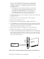
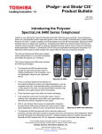
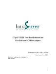
FiberOptic Card
Quick Installation Guide
This quick installation guide provides instructions for installing a 100Base-FX
PCI FiberOptic Card.
1-1 Introducing the FiberOptic Cards
SIIG's line of fiber optic Fast Ethernet 100Base-FX PCI cards fully
comply with all IEEE 802.3u standards. Four LED indicators are
provided on the bracket to help oversee the network/board link,
activities, collision and full-duplex status. The following models are
available :
• FiberOptic Card-ST (multi-mode)
• FiberOptic Card-SC (multi-mode)
• FiberOptic Card-MT (multi-mode)
• FiberOptic Card-VF (multi-mode)
Features/Specifications
• Standards: IEEE 802.3u Fast Ethernet 100Base-FX
• Bus Type: 32-bit PCI
• Fiber Optic Connector:
ST/SC/MT-RJ/VF connector (multi-mode), Tx/Rx
• Fiber Optic Cable:
50/125, 62.5/125 or 100/140 µm (multi-mode)
• Data Transfer Rate/Mode: Up to 100Mbps, half- or full-duplex
• LED Indicators:
LED
Color
ACT
LINK
FDX
COL
Green
Green
Green
Green
Function
Blinks when any traffic is present
Lit when fiber cable connection is good
Lit when full-duplex mode is active
Blinks when collision signal is present
• NOS Supported: Windows 95/98, Windows NT, Windows
2000, Windows for Workgroups, NetWare, IntraNetWare,
Microsoft LAN Manager, OS/2 Warp, IBM LAN Server,
SCO UNIX
04-0176A
1
• Power Requirement: 0.2A @ +5V
• Operating Temperature: 32° to 122° (0° to 50°C)
• Storage Temperature: -40° to 158°F (-40° to 70°C)
• Relative Humidity: 5% to 90%, non-condensing
• Dimensions: 122mm (L) x 80mm (H)
Maximum Fiber Optic Cable Lengths
Full-duplex Switch via Fiber:
Multi-mode
Half-duplex Switch via Fiber:
Multi-mode
Node to Node:
Node to Hub
Hub to Hub:
2000 m
2000 m
2000 m
Node to Node:
Node to Hub
Hub to Hub:
412 m
412 m
412 m
System Requirements
• Pentium-class system with one available 32-bit PCI slot
• Windows for Workgroups, Windows 95 or later,
Microsoft LAN Manager, OS/2 Warp, IBM LAN Server,
NetWare, IntraNetWare, or SCO UNIX operating system
Unpacking
Before installing your FiberOptic Card, verify that the following items
are included in the packaging carton:
• FiberOptic Card
• Two LAN driver diskettes
• This Quick Installation Guide
Please notify your dealer if any item is damaged or missing.
2-1 Hardware Installation
No specific setup of your PCI FiberOptic Card is needed. Simply install
the card following the standard procedures for any PCI card.
General instructions for installing the card are provided below, since
the design of computer cases and motherboards varies. Refer to your
computer’s reference manual for further information, if needed.
2
Caution: Static Electricity Discharge may permanently
damage your system. To avoid possible static electricity
discharge during the installation, please follow the
guidelines below:
• Discharge any static electricity build up in your body
by touching a large grounded metal surface or the
computer’s case (if plugged in), for a few seconds.
• During the installation, avoid any contact with internal
parts. Handle cards only by their external edges.
1. Turn OFF the power to your computer and any other connected
peripheral devices.
2. Unplug the power cord from the back of the computer.
3. Remove your computer’s cover.
4. Remove the slot bracket from an available 32-bit PCI slot.
5. To install the card, carefully align the card's bus connector with the
selected PCI slot bus connector on the motherboard. Push the board
down firmly, but gently, until it is well seated.
6. Replace the slot bracket's holding screw to secure the card.
7. Replace the computer cover and reconnect the power cord.
8. Connect a fiber cable between the FiberOptic card's Tx (transmit)
port and connecting device's Rx (receive) port. Connect another
fiber cable between the card's Rx (receive) port and the connecting
device's Tx (transmit) port.
LINK
ACT
FDX
COL
Connecting
Device
Tx
FiberOptic
Card
Tx
Rx
Rx
Fiber Cable Connection Between FiberOptic Card and Device
The hardware installation is now complete.
3
3-1 Software Installation
This section will guide you through the installation of the Microsoft
Windows software drivers.
Please refer to the appropriate "read.me" files on
the provided driver diskettes for installing other
network operating system drivers.
Windows 95
Perform the steps below to install the following Windows 95 driver
files:
Location of Driver: A:\WIN95 \DC1430.SYS
\NET143F.INF
\OEMSETUP.INF
1. When Windows 95 boots up after installing the card, a "New
Hardware Found" dialog box will appear and the "PCI Ethernet
Controller" will be identified.
2. At the "Add New Hardware Wizard" window, click "Next".
Then click "Other Locations".
3. Insert the Windows Driver Installation Diskette 1 in the floppy
drive.
4. Type a:\win95 in the location box. Click "OK", then
click "Finish".
5. From the "Insert Disk" window, click "OK". When the "Copying
Files" dialog box appears, type in a:\win95 and click "OK"
again.
6. When Windows prompts for the Windows 95 CD, insert the
Windows 95 CD into the CD-ROM drive. Type D:\setup and
click "OK". (Assuming "D" is the CD-ROM drive letter.)
7. Click on "Finish" and restart the system when prompted for the
driver to take effect.
Note: The FiberOptic Cards support 100Mbps speed only. You may
select 100 full-duplex or half-duplex mode configuration for
connection type. The default is 100 full-duplex mode.
An invalid connection type will not work in network connection.
4
Windows 98/98SE
Perform the steps below to install the Windows 98 driver files,
which are built into Windows98/98SE.
1. When Windows 98/98SE boots up after installing the card,
a "New Hardware Found" dialog box will appear and the
detected Ethernet Adapter will be identified.
2. At the "Add New Hardware Wizard" window, click "Next".
3. Select the “Search for the best driver for your device
(Recommended)" option. Click “Next” to continue.
4. "Uncheck" all option boxes. Click "Next" and click "Next" again.
5. Click "Next" again. When prompted for the Windows
CD, insert the Windows 98 CD into the CD-ROM drive.
Type D:\win98 and click "OK". (Assuming "D" is the CD-ROM
drive letter.)
6. Click on "Finish" and restart the system when prompted for the
driver to take effect.
Note: The FiberOptic Cards support 100Mbps speed only. You may
select 100 full-duplex or half-duplex mode configuration for
connection type. The default is 100 full-duplex mode.
An invalid connection type will not work in network connection.
5
Windows NT 4.0
Perform the steps listed below to install the following Windows NT 4.0
driver files:
Location of Driver: A:\WINNT\DC21X4.SYS
\OEMSETUP.INF
1. In “My Computer” of NT desktop, select the “Control Panel” icon.
2. In the Control Panel window, double-click on the “Network” icon.
3. In the Network Settings dialog box, choose “Adapters”, then click
the “Add” button.
4. Click on “Have Disk” and insert the Windows Driver Installation
Diskette 1 into the floppy drive.
5. Type a:\winnt and click "OK".
6. Click "OK" when the "100Fx Fast Ethernet Adapter" is displayed.
7. NT will then perform the binding process. If any additional
network software options were installed, you may be prompted for
specific information for these packages. Click "OK" when the dialogue
box shows "100 Base-Fx (Fx100) Full Duplex".
8. Enter settings and restart your system to acquire network service.
Note: The FiberOptic Cards support 100Mbps speed only. You may
select 100 Full-duplex or Half-duplex mode configuration for
connection type. The default is 100 Full-duplex mode.
An invalid connection type will not work in network connection.
Windows 2000
Windows 2000 will automatically load the driver for this adapter. If you
are prompted to insert the Windows 2000 CD, insert the CD in the
CD-ROM drive and "browse" to the I386 folder to finish the installation.
Other OSes
Please refer to the appropriate read.me file on the driver
installation diskettes for installation instructions. These files can be
opened with either Notepad or Wordpad.
6
4-1 Technical Support & RMA
Questions? SIIG’s On-line Support has the answers! Simply visit
our web site at www.siig.com and click on the ON-LINE SUPPORT
icon for instant technical support. You may also e-mail us on-line
at: http:\www.siig.com/technical_support_form.html
If you need additional help, Tech Support Specialists are available
from 8:00 a.m. to 5:00 p.m. Mon. – Fri., PST at (510) 353-7542.
In order for SIIG’s Technical Support to give you prompt service,
you will need the following information.
Part Number: ______________________________________
Computer Configuration: ___________________________
Return Merchandise Authorization (RMA)
SIIG warrants to the original buyer of the product that the hardware
is free of defects in materials and workmanship for a period of five
years from the date of purchase. If your product fails to be in good
working order during the warranty period, you may return it to SIIG
for repair or replacement at SIIG's option. To return a product:
Step 1: Call SIIG's RMA Department
Call the RMA Department at (510) 413-5333 for a Return Merchandise
Authorization (RMA) number. To get a RMA number, you must
have your product serial number. The serial number is located on
the side of the box it came in and on the back of the product.
Step 2: Complete the RMA form
• Fill out the RMA form and include it with the product.
• Properly pack the product for shipping. All software, cable(s) and
accessories that came with the original package must be included.
• Clearly write your RMA number on the top of the returned package
and on the accompanying RMA form. SIIG will refuse any shipping
package, and not be responsible for a product returned without
a RMA number posted on the outside of the shipping carton.
Step 3: Ship the product
You are responsible for the shipping cost to SIIG at the following
address:
SIIG, Inc. RMA#_______________
6078 Stewart Ave.
Fremont, CA 94538
SIIG will ship the repaired or replaced product via UPS Ground or US
Mail at no cost to you.
7