1
Operator's Manual
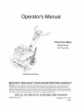
Front Tine Tillers
Model Series
340 Thru 390
Model Series 390 Shown
IMPORTANT:
READ SAFETY
RULES AND INSTRUCTIONS
CAREFULLY
Warning:
This unit is equipped with an internal combustion engine and should not be used on or near any unimproved forestcovered, brush-covered or grass-covered land unless the engine's exhaust system is equipped with a spark arrester meeting
applicable local or state laws (if any), If a spark arrester is used, it should be maintained in effective working order by the operator,
In the State of California the above is required by law (Section 4442 of the California Public Resources Code), Other states may have
similar laws, Federal laws apply on federal lands, A spark arrester for the muffler is available through your nearest engine authorized
service dealer or contact the service department, P,O, Box 361131 Cleveland, Ohio 44136-0019,
MTD LLC, P.O. BOX 361131 CLEVELAND,
PRINTED IN U.S.A.
OHIO 44136-0019
FORM NO. 770-10135E
(10/05)
TABLEOFCONTENTS
Content
Page
Content
Important Safe Operation Practices
Assembling Your Tiller
Know Your Tiller
3
5
7
Maintaining Your Tiller
Troubleshooting
Illustrated Parts List
Operating Your Tiller
Making Adjustments
8
11
Warranty
Page
11
14
16
24
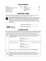
FINDINGMODELNUMBER
This Operator's Manual is an important part of your new tiller. It will help you assemble, prepare and
maintain the unit for best performance. Please read and understand what it says.
Before you start assembling your new equipment, please locate the model plate on the
equipment and copy the information from it in the space provided below. A sample model plate is
also given below. You can locate the model plate by standing at the operating position and
looking down at the right side of the frame. This information will be necessary to use the
manufacturer's web site and/or help from the Customer Support Department or an authorized
service dealer.
Copy the model number here:
_)ff
Copy the serial number here:
M*D LLC
P. O. BOX
CLEVELAND,OH
361131
44136
338-228-4683
k www.mLuprouucLs,com_-'-' _
880-888-731
O ,
CUSTOMER
SUPPORT
Please do NOTreturn theunit to the retailer from where it waspurchased,withoutfirst contactingCustomerSupport.
If you have difficulty assembling this product or have any questions regarding the controls, operation or
maintenance of this unit, you can seek help from the experts. Choose from the options below:
Visit mtdproducts.com
for many useful suggestions. Click on Customer Support button and
you will get the four options reproduced here. Click on the appropriate button and help is
immediately available.
8nswer
you
_ mouse click _w_/
8__
_nswer
you __
looking for could be just
_ mouse click _w_y!
If you prefer to reach a Customer Support Representative, please call 1-800-800-7310.
En ine
M nual
The engine manufacturer is responsible for all engine-related issues with regards to
performance, power-rating, specifications, warranty and service. Please refer to the engine
manufacturer's Owner's/Operator's Manual, packed separately with your unit, for more
information.
SECTION1: IMPORTANT
SAFEOPERATION
PRACTICES
WARNING: This symbol points out important safety instructions which, if not followed, could endanger
the personal safety and/or property of yourself and others. Read and follow all instructions in this
manual before attempting to operate this machine. Failure to comply with these instructions may result
in personal injury. When you see this symbol-- heed its warning.
WARNING: Engine exhaust, some of its constituents, and certain vehicle components contain or emit
chemicals known to State of California to cause cancer and birth defects or other reproductive harm.
DANGER:
This machine was built to be operated according to the rules for safe operation in this
manual. As with any type of power equipment, carelessness or error on the part of the operator can
result in serious injury. This machine is capable of amputating hands and feet. Failure to observe the
following safety instructions could result in serious injury or death.
Training
1.
2.
3.
4.
5.
Read, understand, and follow all instructions on the
machine and in the manual(s) before attempting to
assemble and operate. Keep this manual in a safe
place for future and regular reference and for
ordering replacement parts.
Be familiar with all controls and their proper
operation. Know how to stop the machine and
disengage them quickly.
Never allow children under 14 years old to operate
this machine. Children 14 years old and over should
read and understand the operation instructions and
safety rules in this manual and should be trained
and supervised by a parent.
Never allow adults to operate this machine without
proper instruction.
Keep bystanders, helpers, pets and children at least
75 feet from the machine while it is in operation.
Stop machine if anyone enters the area.
7.
8.
9.
10.
11.
12.
Use only an approved gasoline container.
Extinguish all cigarettes, cigars, pipes and other
sources of ignition.
Never fuel machine indoors.
Never remove gas cap or add fuel while the engine
is hot or running.
Allow engine to cool at least two minutes before
refueling.
Never over fill fuel tank. Fill tank to no more than Y2
15.
inch below bottom of filler neck to provide space for
fuel expansion.
Replace gasoline cap and tighten securely.
If gasoline is spilled, wipe it off the engine and
equipment. Move machine to another area. Wait 5
minutes before starting the engine.
Never store the machine or fuel container inside
16.
near an open flame, spark or pilot light (e.g.
furnace, water or space heater, clothes dryer etc.).
Allow machine to cool 5 minutes before storing.
13.
14.
Preparation
Operation
1.
1.
2.
3.
4.
5.
6.
Thoroughly inspect the area where the equipment is
to be used. Remove all stones, sticks, wire, and
other foreign objects which could be tripped over
and cause personal injury.
Wear sturdy, rough-soled work shoes and close
fitting slacks and shirt. Loose fitting clothes or
jewelry can be caught in movable parts. Never
operate this machine in bare feet or sandals.
Disengage clutch levers and shift (if provided) into
neutral ("N") before starting the engine.
Never leave this machine unattended with the
engine running.
Never attempt to make any adjustments while
engine is running, except where specifically
recommended in the operator's manual.
To avoid personal injury or property damage use
extreme care in handling gasoline. Gasoline is
extremely flammable and the vapors are explosive.
Serious personal injury can occur when gasoline is
spilled on yourself or your clothes which can ignite.
Wash your skin and change clothes immediately.
2.
3.
4.
5.
6.
7.
8.
Do not put hands or feet near rotating parts. Contact
with the rotating parts can amputate hands and feet.
Do not operate machine while under the influence
of alcohol or drugs.
Never operate this machine without good visibility
or light. Always be sure of your footing and keep a
firm hold on the handles.
Keep bystanders, helpers, pets, and children at
least 75 feet from the machine while it is in
operation. Stop the machine if anyone enters the
area.
Be careful when tilling in hard ground. The tines
may catch in the ground and propel the tiller
forward. If this occurs, let go of the handle bars and
do not restrain the machine.
Exercise extreme caution when operating on or
crossing gravel surfaces. Stay alert for hidden
hazards or traffic. Do not carry passengers.
Never operate the machine at high transport
speeds on hard or slippery surfaces.
Exercise caution to avoid slipping or falling.
9.
10.
Lookdownandbehindandusecarewhenin
Do not change the engine governor settings or
reverse
orpullingmachine
towards
you.
over-speed the engine. The governor controls the
Starttheengineaccording
totheinstructions
found
maximum safe operating speed of the engine.
inthismanual
andkeepfeetwellawayfromthe
Maintain or replace safety and instruction labels, as
tinesatalltimes.
necessary.
6.
Afterstriking
a foreignobject,stoptheengine,
Follow this manual for safe loading, unloading,
disconnect
thesparkplugwireandground
against
transporting, and storage of this machine.
Never store the machine or fuel container inside
theengine.
Thoroughly
inspect
themachine
forany 7.
damage.
Repair
thedamage
beforestarting
and
where there is an open flame, spark or pilot light
operating.
such as a water heater, furnace, clothes dryer etc.
Disengage
allclutchleversandstopengine
before
Always refer to the operator's manual for proper
youleavetheoperating
position
(behind
the
instructions on off-season storage.
9.
handles).
Waituntilthetinescometoacomplete
If the fuel tank has to be drained, do this outdoors.
10.
stopbeforeunclogging
thetines,making
any
Observe proper disposal laws and regulations for
adjustments,
orinspections.
gas, oil, etc. to protect the environment.
Neverrunanengine
indoorsorina poorly
ventilated
area.Engineexhaust
contains
carbon
YourResponsibility
monoxide,
anodorless
anddeadlygas.
1.
Restrict the use of this power machine to persons
Mufflerandenginebecome
hotandcancausea
who read, understand and follow the warnings and
burn.Donottouch.
instructions in this manual and on the machine.
Usecautionwhentillingnearfences,buildings
and
2.
The safety label on the tiller is reproduced below for
underground
utilities.Rotating
tinescancause
your review. To ensure safe operation of the tiller,
property
damage
orpersonal
injury.
follow the instructions on all labels closely.
Donotoverload
machine
capacity
byattempting
to
tillsoiltodeepattofastofarate.
Ifthemachine
shouldstartmaking
anunusual
noise
orvibration,
stoptheengine,disconnect
thespark
plugwireandgrounditagainsttheengine.Inspect
TO AVOID SERIOUS INJURY
READTHE_ERATOR'SMANUAL,
thoroughly
fordamage.
Repairanydamage
before
KNOWLOCATION
ANDFUNCTIONS
startingandoperating.
OFALLCONTROLS.
Keepallshields,guardsandsafetydevices
inplace
KEEPALLSAFETYDEVICES
AND
andoperating
properly.
SHIELDS
INPLACEANDWORKI_,
NEVERALLOWCHILDREN
OR
Neverpickuporcarrymachine
whiletheengineis
UNINSTRUCTED
ADULTS
TO
running.
OPERATETILLER,
Useonlyattachments
andaccessories
approved
by
SHUTOFFENGINEBEFORE
themanufacturer.
Failuretodoso,canresultin
UNCLOGGI_TINESOR MAKING
REPAIRS,
personal
injury.
KEEPBYSTANDERS
AWAYFROM
Ifsituations
occurwhicharenotcovered
inthis
MACHINE,
manual,
usecareandgoodjudgment.
Contact
your
KEEPAWAYFROMROTATING
dealerortelephone
1-800-800-7310
forassistance
PART&
andthenameofyournearest
servicing
dealer.
USEEXTREMECAUTIONWHEN
4,
5,
11.
12.
13.
14.
15.
16.
17.
18.
19.
20.
21.
8,
Maintenance& Storage
1.
2.
3.
Never tamper with safety devices. Check their
proper operation regularly.
Check bolts and screws for proper tightness at
frequent intervals to keep the machine in safe
working condition. Also, visually inspect machine for
any damage.
Before cleaning, repairing, or inspecting, stop the
engine and make certain the tines and all moving
parts have stopped. Disconnect the spark plug wire
and ground it against the engine to prevent
unintended starting.
REVERSING
OR PULLINGTHE
MACHINETOWARDSYOU_
SECTION2: ASSEMBLING
YOURTILLER
NOTE: This operator's guide covers three different
model tillers. Model series 340 thru 345 have forward
)iece
tine drive only. Model series 390 has both forward and
reverse tine drive. Follow only the instructions which
pertain to your model tiller. See the model plate on your
tiller for the correct model number.
Depth
Stake
NOTE: References to right or left side of the tiller are
determined from behind the unit in the operating
position.
Screws
RemovingUnitFromCarton
•
Remove staples, break glue on top flaps, or cut
tape at carton end and peel along top flap to open
carton.
•
Remove all loose parts included with unit (i.e.,
operator's manual, etc.)
Cut corners and lay carton down flat.
Remove packing material.
Roll or slide unit out of carton. Check carton
•
•
•
•
Figure 1
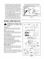
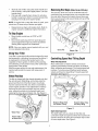
AttachingHandleAssembly
•
Remove the hex bolt and cupped washer from the
top right side of the frame halves. Hold the cable
guide bracket on the left side of the frame as it will
fall when the bolt is removed. See Figure 2.
Hand __
Knob
....
thoroughly for loose parts.
Extend control cable(s) to the rear of the tiller and
lay them on the floor. Be careful not to bend or kink
control cable(s).
Ha_
HexBolt&F
\ _ _
Cupped Washer _\_
IMPORTANT: This unit is shipped without gasoline or oil
in the engine. Be certain to service engine with gasoline
and oil as instructed in the separate engine manual
before operating your machine.
FrameHa'ff_'_
Figure 2
BeforeAssembly
•
and
ground Disconnect
it against the
prevent
WARNING:
theengine
spark toplug
wire
unintended starting.
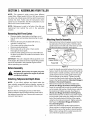
AttachingTailpieceAndDepthStake
NOTE: If your tiller's tailpiece and depth stake has
been already assembled before shipping, proceed to
the next section. If it is unassembled, follow the steps
below.
Remove the two self-tapping screws on the frame.
Slide the tailpiece into the frame with the lower hole in
the tailpiece toward the front. Secure with screws just
removed. See Figure 1.
•
•
•
•
•
Insert the handle assembly between the two frame
halves. Insert the hex bolt just removed through the
frame halves, handle assembly, and into the cable
guide bracket (notch in cable guide bracket goes
over the flange on the frame). Tighten securely.
Loosen the hand knob which secures the handle
brace to the handle assembly. (Standard Briggs &
Stratton & Tecumseh Engines).
Remove the hand knob from the handle brace.
(Honda and Briggs & Stratton Intek Engines).
Insert the carriage bolt through the welded bracket
on the handle, bell washer, handle brace, and into
the hand knob. Tighten securely. See Figure 3.
(Honda and Briggs & Stratton Intek Engines).
Remove the hex lock nut from on top of the engine,
just to the left of the spark plug. Attach the curved
end of the handle brace to the top of the engine,
using hex lock nut just removed. Tighten securely.
See Figure 3. (Standard Briggs & Stratton &
Tecumseh Engines).
Select one of the three handle height positions
(three notches in welded bracket), and tighten the
hand knob to secure the handle in desired position.
Make certain carriage bolt is seated securely into
one of the three positions provided.
•
Handle
/
Carriage Bolt
\-. \
Bell
Washer
Hand
Welded
__
_""_
•
•
Knob
Handle Brace
Honda and Briggs & Stratton Intek Engines
•
Loosen the hex nut on the threaded rod near the
end of the cable, and move it up the rod as far as it
will go.
Unthread the rod from the rest of the cable. Hook
the "Z" end of the rod into the bracket underneath
the handle assembly from the right hand side. See
Figure 4.
Thread the rod back into the cable until the cable is
straight. Do not tighten it enough to put any tension
on the spring.
Thread the hex nut down against the end of cable.
Use a pair of pliers and a wrench to lock the nut
against the rod.
NOTE: Do not overtighten control cable. Too much
tension may cause it to break when engaged.
Hex Lock Nut
Handle
Threaded
Rod
"Z" End
Hooked In
Bracket
Hex Nut
Cable
Briggs & Stratton Standard Engine
Model Series 340 thru 345
Spark
Plug
Figure 4
Handle
Brace
ReverseCable(ModelSeries300Only)
The reverse clutch cable is the cable which is attached
closer to the front of the tiller. Attach the end of the
reverse cable to the reverse tine drive clutch lever,
above the handle assembly, in the same manner as
'ou attached the forward cable. See Figure 5.
Reverse Tine
Engagement Lever
Z End Hooked
in
Hex Lock
Nut
Tecumseh Engine
Figure 3
Rod
Forward Tine
Engagement
Hex
AttachingClutchControlCable(s)
NOTE: If your tiller's clutch control cable(s) have been
already assembled before shipping, proceed to the next
section. If unassembled, follow the steps below.
Forward Cable
Attach the end of the forward cable to the bracket
underneath the handle assembly as follows. (On model
series 390, the forward clutch cable is the cable which
is attached closer to the rear of the tiller).
in Bracket
Rod
Figure 5
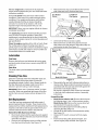
FinalClutchAdjustment
To check the clutch cable adjustment, proceed as
follows:
•
•
•
Disconnect
thesparkplugwireandmoveitaway
fromthesparkplugtopreventaccidental
starting.
Engageandreleasethetineengagement
handle,
thenthereversetineengagement
lever(model
series390only).Ifanexcessivenoiseisheard
whenreleasing
eitherthetinedriveclutchhandleor
lever,thecablemaybetooloose.Adjusteitherthe
forwardor reverseclutchcablebyloosening
the
hexnut,threading
therodintothecableoneortwo
turns,thenretightening
thenut.
Withtineengagement
handleinneutral(released)
asshowninFigure6,pullthestarterropeseveral
times.Thetinesshouldnotturn. Iftheyturn
forward,loosenthehexnutontheforwardcable
(underneath
thehandleassembly).
Iftheyturn
towardtherear(modelseries390only),loosenthe
hexnutonthereversecable(abovethehandle
assembly).
Unthread
therodfromthecable2 or3
turns.Retighten
thehexnut,andcheckagainfor
correctadjustment.
SeeFigure6.
Forward Tine
Engagement Lever
Engagement Lever
Model Series 340 thru 345
Model Series 390
Figure 6
SECTION3: KNOWYOURTILLER
all instructions
and warnings on the
WARNING: Read, understand, and follow
machine and in this manual before
operating.
Run
Throttle Control
The throttle control lever is located on the engine. It
controls the engine speed and stops the engine. See
Figure 7.
Briggs and Stratton Intek
Choke
ChokeLever (ModelSeries340/390)
The choke lever is located above the throttle control. It
is used to enrich the fuel mixture when starting a cold
engine. See Figure 7.
Primer Button(Model 345)
The primer button is located behind the air cleaner. It is
used to enrich the fuel mixture in the carburetor when
starting a cold engine. See Figure 7.
....
Throttle Control
Briggs and Stratton Standard
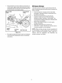
ForwardTine EngagementHandle
The forward tine engagement handle is located
beneath the tiller handle. Squeezing the handle up
against the tiller handle engages the tines. Release the
handle to stop the tines. See Figure 8.
Air
Cleaner
ReverseTine Drive ClutchLever
Primer
(ModelSeries390 0nly)
The reverse tine drive clutch lever is located on top of
the handle panel. Pull the lever to the rear to move the
tines in reverse. Release the lever to stop the reverse
tine drive. See Figure 8.
Control
NOTE: Never engage both the forward and reverse tine
drives at the same time. Engaging both forward and
reverse tine drives at the same time could damage the
belt drives and cause the engine to stall.
7
Figure 7
DepthStake
Tines And End Caps
The depth stake controls the tilling depth. Refer to
OPERATING YOUR TILLER in Section 4.
The tilling tines and end caps (are used to cultivate,
furrow, and prepare your garden for seeding. The end
caps (Model Series 390 only) are used to avoid tilled
soil from overflowing onto unwanted areas.
Engagement
Handle
Hand
Knob
\
\
-- Forward Tine
Engagement
Handle
\
\
\
Depth
Stake
End Cap
Model Series 390 Shown
Figure 8
SECTION4: OPERATING
YOURTILLER
GasandOil Fill up
Service the engine with gasoline and oil as instructed in
the separate engine manual packed with your tiller.
Read instructions carefully.
•
Pull rope with a rapid, continuous, full arm stroke.
Keep a firm grip on starter handle. Let rope rewind
slowly. Do not let starter handle snap back against
starter.
•
Repeat preceding instructions until engine starts.
When engine starts, move/push in choke lever on
engine halfway between CHOKE and RUN.
Move throttle control to IDLE position for a few
minutes warm-up. Move/push in choke lever to
RUN position as engine warms up.
StartingEngine
•
,_
front of the tiller while the engine is
WARNING: Be sure no one is standing in
running or being started.
Models 340, 342, & 395
•
•
•
•
•
Attach spark plug wire to spark plug. Make certain
the metal loop on the end of the spark plug wire
(inside the boot) is fastened securely over the metal
tip on the spark plug.
Make certain all controls are in the neutral position
(released). See Figure 6.
Place the throttle control lever in FAST position.
See Figure 7.
Move/pull out choke lever to CHOKE position. (A
warm engine requires little or no choke.)
Grasp starter handle and pull rope out slowly until
engine reaches start of compression cycle (rope
will pull slightly harder at this point). Let the rope
rewind slowly.
Models343 & 345
•
•
•
•
Attach spark plug wire to spark plug. Make certain
the metal loop on the end of the spark plug wire
(inside the boot) is fastened securely over the metal
tip on the spark plug.
Make certain all controls are in the neutral position
(released). See Figure 8.
Place the engine speed control in the START
position.
Push primer two (2) or three (3) times. Wait about
two (2) seconds between each push.
NOTE: Primer may be needed to restart a warm engine
after a short shutdown.
•
•
Stand at side of tiller. Grasp the starter handle and
pull out slowly, until it pulls slightly harder. Let rope
rewind slowly.
Pull rope with a rapid full arm stroke. Do not allow
handle to snap back. Allow it to rewind slowly while
keeping a firm hold on the starter handle.
RemovingEndCaps(ModelSeries390 only)
The end cap, which are used to avoid tilled soil from
overflowing onto unwanted areas, are removable from
the outer axle. Remove the hairpin clip and clevis pin
that is securing each end cap and slide end cap off the
axle. See Figure 10.
NOTE: If engine fails to start after three (3) pulls, push
primer two (2) times and pull starter rope again.
•
Repeat previous steps until engine starts. Refer to
engine manual for additional engine information.
ToStopEngine
•
•
Move throttle control lever to STOP or OFF
position.
Disconnect spark plug wire from spark plug and
ground against the engine to prevent accidental
starting while equipment is unattended.
NOTE: See your engine manual packed with your un#
for more detailed instructions.
Clevis Pin
UsingYourTiller
Hairpin
Figure 10
Your tiller is a precision built machine designed for seed
bed preparation, cultivating, furrowing and mulching. It
is engineered to minimize the hardest work in the
vegetable or flower garden, to till the soil for planting
and cultivating, and to perform many other useful labor
saving tasks in the garden.
With the proper amount of care and maintenance, this
machine will provide the owner with many years of
service.
ControllingSpeedAndTillingDepth
Wheel YokeAdjustment
Place wheel yoke so that the wheels are forward
(nearest point between wheels and tines) for shallow
tilling, cultivating and transport. The forward speed will
increase. Turn yoke around (farthest point between
wheels and tines) for deep tilling. Forward speed will
decrease. See Figure 11.
WheelPosition
The tiller is shipped with the wheels adjusted such that
the unit sits level. While tilling, as the tines enter the
ground and the front of the tiller lowers, the wheels
must be raised to level the unit, which is essential for
proper engine operation. This adjustment is made by
removing the clevis pin and hairpin clip from wheel
yoke, raising the wheels to the desired height, and
replacing the clevis pin and hairpin clip. See Figure 9.
Depth Stake
Position Wheel Yok!
For Shallow Tilling
Yoke
For Deep Tilling
Figure 11
DepthStake Adjustment
Wheel
The depth stake acts as a brake for the tiller and
controls the depth and speed at which the machine will
operate. Remove the clevis pin and hairpin clip to raise
or lower depth stake. See Figure 9.
Hairpin Clips
& Clevis
Figure 9
Handle Pressure
Transport
,l
_i_epth
Further control of tilling depth and travel speed can be
obtained by variation of pressure on the handles.
•
A downward pressure on the handles will reduce
the working depth and increase the forward speed.
•
An upward pressure on the handles will increase
the working depth and reduce the forward speed.
The type of soil and working conditions will determine
the actual setting of the depth stake and the handle
pressure required.
Position
Stake/
Shallow Tilling
Throttle Control
The throttle control lever adjusts the engine speed and
stops the engine. With the throttle control lever pushed
completely forward, the carburetor is in START
position. Pulling the throttle control back slightly adjusts
the engine speed to FAST. Pulling the throttle back
further reduces the engine speed to SLOW. Pull the
throttle completely back to stop the engine.
Use maximum engine speed for deep tilling. Move the
throttle control to SLOW when transporting the tiller.
\
WheelSettingFor
DeepTilling
\\
Deep Tilling
Figure 12
By increasing the depth of the depth stake, the forward
speed of the machine is reduced and the working depth
is increased. When the depth stake is raised, the
working depth of the machine is reduced and the
forward speed is increased. The working depth of the
machine may be predetermined by setting the depth
stake and wheels so that the wheels are about four
Transporting The Tiller
To transport the tiller to or from the garden, pivot the
depth stake forward, out of the way. See Figure 12.
With the throttle control in SLOW position, the unit will
walk freely on top of the lawn. If the operator does not
allow the tiller to move freely, the unit will start to till the
surface.
inches from the ground when the tines and depth stake
are resting on the ground. This setting will permit a
working depth of about four inches. When presetting
the working depth, the handles should be adjusted so
the hand grips are a little above waist. The tiller will be
lower when the tines and depth stake penetrate the
ground. See Figure 12.
Cultivating
For cultivating, a two to three inch depth is desirable.
Setting the wheels and depth stake so that the wheels
are about two inches above the ground while the tiller is
resting on the tines and depth stake will allow the
machine to work at cultivating depth. The throttle
should be set to control forward movement to a slow
walking speed. With the outer tines installed, the
working width of the machine is 22 or 24 inches. For
cultivation, this may be reduced to 13 inches by
removing the outer tines. Refer to the Adjustment
Section. When laying out plant rows, be sure to allow
enough width to permit cultivation between the rows. In
growing corn or similar crops, check-row planting will
permit cross cultivation and practically eliminate hand
hoeing. See Figure 14.
The tiller has many uses other than tilling and
cultivating a garden. One of these is the preparation of
lawn area for seeding. The tiller will prepare a deep
seed bed which will be free of hard untilled spots,
allowing a better stand of grass to grow. The tiller is
very useful for loosening hard soil for excavation with a
shovel. No tedious handwork will be necessary. Your
tiller may be used for mixing compost in the pile, or for
mixing it with the soil in your garden. This should be
done after the soil has been broken to the full working
depth. The compost should be worked in to a depth of
six to seven inches. This may be done by working the
length of the garden and then by making separate
passes across its width. The addition of decayed
Figure 13
When tilling, leave approximately 8 inches of untilled
soil between the first and second tilling paths, then
make the third path between the first and second. In
some soils, the desired depth is obtained the first time
over the garden. In other soils, the desired depth is
obtained by going over the garden two or three times. In
the latter case, the depth stake should be lowered
before each succeeding pass over the garden. Passes
should be made across the length and width of the
garden alternately. Rocks which are turned up should
be removed from the garden area. See Figure 13.
10
organicmatterwillsubstantially
increase
thefertilityof
yourgarden.Forproperdecayingaction,fertilizer
shouldbeappliedandworkedinwiththemulch
materials.
Breakingupleavesandstrawandmixingit
withseveralinchesofsoilcausesthesoilto hold
moisturelongerandallowsproperaerationoftheplant
rootsystem.Thisalsoretardsthegrowthofweeds.
A
O
0
9
O
O O
O
O
'_AF
J
m
m
_
m
! 1k,,,,,%
Figure 14
SECTION5: MAKINGADJUSTMENTS
_,
and
ground Disconnect
it against the
the spark
engineplug
before
WARNING:
wire
performing any adjustments.
EngineAdjustment
Refer to the separate engine manual for engine
adjustment instructions.
I_
22"
_1
I_
24"
_1
WheelAdjustments
To adjust the wheel yoke and wheel position, refer to
the Operating Section.
ClutchControlAdjustments
To adjust the clutch controls, refer to the Final
Adjustment section of assembly instructions.
DepthStakeAdjustment
To adjust the depth stake, refer to the Operating
Section.
TineWidthAdjustment
The tilling width of the unit is 22 inches. Tilling width can
be increased to 24 inches by removing the clevis pins
and hairpin clips, sliding the outer tines out one inch,
and securing in this position with the clevis pins and
hairpin clips. For cultivation, reduce the tine width to 13
inches by removing the outer tines completely.
See Figure 15.
Figure 15
SECTION6: MAINTAININGYOURTILLER
WARNING: Disconnect the spark plug wire
and ground it against the engine before
performing any repairs or maintenance.
Engine
Refer to the separate engine manual for engine
maintenance instructions.
11
Maintain engine oil as instructed in the separate
engine manual packed with your unit. Read and follow
instructions carefully.
Remove the hex stop nut and flat washer from the
side of the belt cover. Remove belt cover.
Hex Washer
Service air cleaner every ten hours under normal
conditions. Clean every hour under extremely dusty
conditions. Poor engine performance and flooding
usually indicates that the air cleaner should be
serviced. To service the air cleaner, refer to the
separate engine manual packed with your unit.
Lock Nut &
Flat Washer
Belt Cover
IMPORTANT: Never run your engine without air cleaner
completely assembled.
The spark plug should be cleaned and the gap reset
every 25 hours of engine operation. Spark plug
replacement is recommended at the start of each tiller
season; check engine manual for correct plug type and
gap specification.
Figure 16
Lift the belt off the transmission pulley.
Remove the hex nut which secures the reverse
idler pulley to the idler bracket. Slide idler pulley out
and remove the belt. See Figure 17.
Clean the engine regularly with a cloth or brush. Keep
the cooling system (blower housing area) clean to
permit proper air circulation which is essential to engine
performance and life. Be certain to remove all dirt and
combustible debris from muffler area.
Forward
Belt
Reverse Idler
Pulley_
Lubrication
Pivot Points
Remove the belt cover and lubricate all moving parts
and pivot points at least once a season using SAE 30
engine oil.
Hex
Chain Drive
The chain case is pre-lubricated and sealed at the
factory.
Engine Pulley
Cleaning
TineArea
Reverse Be/
Transmission
Pulley
Model 390 Shown
Clean the underside of the tine shield after each use.
The dirt washes off the tines easier if rinsed off
Figure 17
immediately instead of after it dries. Always towel dry
the tiller afterwards and apply a light coat of oil or
silicone to prevent rusting or water damage.
Reassemble the new belt, following instructions in
reverse order. Make certain the reverse drive belt is
assembled with the wide side of the belt against the
transmission and engine pulleys.
Be certain to adjust the clutch control as instructed
in the final clutch adjustment section of assembly
instructions.
IMPORTANT: Never use a "pressure washer" to clean
your tiller. Water can penetrate tight areas of the tiller
and its chain case and cause serious damage to the
unit.
Forward DriveBelt
•
Model Series 340 thru 345: Remove the belt cover
by following steps 1 thru 3 of the previous section.
Model Series 390: Remove the reverse drive belt
as instructed in the previous section.
•
Remove the belt keeper from the idler pulley by
removing the idler pulley nut.
•
Lift belt off the idler pulley and transmission pulley.
See Figure 18.
•
Using a 9/16" wrench, remove bolt from engine
pulley.
•
Push reverse idler pulley bracket forward, and
remove engine pulley and belt. See Figure 18.
BeltReplacement
Your tiller has been engineered with belts made of
special material (Kevlar Tensile). They should not be
replaced with an off-the-shelf belt. If belt replacement is
required, order belt or belts by part number from your
nearest authorized service dealer. See parts list.
ReverseDrive Belt (ModelSeries3(300nly)
•
Disconnect and ground the spark plug wire against
the engine. Remove the belt cover from the left side
of the tiller as follows.
•
Remove two self-tapping screws and flat washers
from the front of belt cover. See Figure 16.
12
Reassemble
thenewbelt,followinginstructions
in
reverseorder.Makecertaintheforwarddrivebeltis
assembled
withthewidesideofthebeltawayfrom
thetransmission
andenginepulleys.
Off-Season
Storage
If the tiller will not be used for a period longer than 30
days, the following steps should be taken to prepare the
tiller for storage.
Transmission
Pulley
Reverse Idler
ley
\
•
Clean the exterior of engine and the entire tiller
thoroughly. Lubricate the tiller as described in the
lubrication instructions.
•
We do not recommend the use of pressure
washers to clean your unit. They may cause
damage to pulleys, bearings, or the engine. The
use of pressure washers will result in shortened life
and reduce serviceability.
Refer to the engine manual for correct engine
storage instructions.
Wipe tines with oiled rag to prevent rust.
Store tiller in a clean, dry area. Do not store next to
corrosive materials, such as fertilizer.
•
•
•
-nglne
Pulley
Forward
Belt
NOTE: When storing any type of power equipment in
an unventilated or metal storage shed, care should be
taken to rustproof the equipment. Using a light oil or
silicone, coat the equipment and especially any
springs, bearings, and cables.
Idler Pulley Nut
Figure 18
Be certain to adjust the clutch control as instructed
in the final clutch adjustment section of assembly
instructions.
13
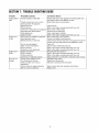
SECTION7: TROUBLE
SHOOTING
GUIDE
Trouble
Possible
Engine fails to
start
Fuel tank empty, or stale fuel.
Engine runs
erratic
Engine overheats
Tines do not
engage
Cause(s)
Throttle control lever not in correct
starting position (if equipped).
Blocked fuel line.
Dirty aircleaner.
Choke not in ON position (if equipped).
Spark plug wire disconnected.
Faulty spark plug.
Engine flooded.
Unit running on CHOKE (if equipped).
Spark plug wire loose.
Blocked fuel line or stale fuel.
Vent in gas cap plugged.
Water or dirt in fuel system.
Dirty air cleaner.
Carburetor out of adjustment.
Engine oil level low.
Dirty air cleaner.
Air flow restricted.
Carburetor not adjusted properly.
Foreign object lodged in tines.
Tine clevis pin(s) missing.
Pulley and idler not in correct
adjustment.
Control cable not adjusted properly.
Belt worn and/or stretched.
Corrective
Action
Fill tank with clean, fresh gasoline. Fuel will not last over
thirty days unless a fuel stabilizer is used.
Move throttle lever to start position.
Clean fuel line.
Refer to the engine manual packed with your unit.
Move switch to ON position.
Connect wire to spark plug.
Clean, adjust gap or replace.
Refer to the engine manual packed with your unit.
Move choke lever to OFF position.
Connect and tighten spark plug wire.
Clean fuel line; fill tank with clean, fresh gasoline. Fuel will
not last over thirty days unless a fuel stabilizer is used.
Clear vent.
Drain fuel tank. Refill with fresh fuel.
Refer to the engine manual packed with your unit.
Refer to the engine manual packed with your unit.
Fill crankcase with proper oil.
Refer to the engine manual packed with your unit.
Refer to the engine manual packed with your unit.
Adjust carburetor as instructed in separate engine manual.
Dislodge foreign object.
Replace tine clevis pin(s).
Take unit to authorized service dealer.
Adjust control cable (see assembly instructions).
Replace belt.
14
NOTES
15
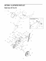
SECTION8: ILLUSTRATED
PARTSLIST
ModelSeries340 Thru345
/
2
7
10
Standard Briggs & Stratton
Tecumseh Engines
48
4
47
\
11
12
45
50
14
17
44
/
21
/
/
37_
32\
_9
19
28
34
I
I
I
I
38
39
/41
/
16
/
42
18
9
46
ModelSeries340 Thru345
Ref.
No.
Part No.
Ref.
No.
Part Description
1.
712 -0442
Acorn Lock Nut 1/4-20
2.
736-3020
Flat Washer.271" I.D.x.630"
3.
731-1599
4.
712-0287
5.
720-0274
6.
Part No.
Part Description
26.
711-1036
27.
736-0119
Spec. Hex Nut
L-Wash. 5/16" I.D.
Handle Cover
28.
710-3008
Hex Bolt 5/16-18 Gr. 5
Hex Nut 1/4-20 Gr.2
29.
786-0129
Cable Guide Bracket
Handle Grip
30.
710-0604
Hex Wash Screw 5/16-18 x.62"
686-0083
Clutch Handle Assembly
31.
710-0602
7.
720-0269
Clutch Grip
32.
738-0934
Hex Wash. Hd. TT-Tap Scr.
Shdl. Bolt 5/16-18
8.
710-0641
786-0138A
Frame (R.H.)
731-1645A
Hex Bolt 1/4-20 x 2.25" Lg. Gr.5
Clutch Handle Holder
33.
9.
34.
786-0139A
10.
736-0140
Flat Washer.385" I.D.x.62" O.D.
35.
736-0171
Frame (L.H.)
Lock Washer 7/16
11.
649-0039
Handle Assembly Comp. t
36.
712-0240
Jam Nut 7/16-20 Gr. 2
649-0022B
Handle Assembly Comp. tt
37.
710-0176
Hex Bolt 5/16-18 x 2.75" Lg.
12.
647-0042
Adjustment Crank t
38.
712-0429
13.
726-0211
U Nut 5/16-18 t
39.
711-0415
Hex Nyloc Nut 5/16-18 Thd.
Clevis Pin
14.
749-1101
Handle Brace t
40.
714-0149B
Cotter Pin
15.
736-0921
Lock Washer 1/2 t
41.
686-0081A
Wheel Hanger Brkt. Assy
16.
710-3194
Hex Bolt 1/2-20 Gr. t
42.
734-1566
17.
786-0005
738-0929
Wheel Ass'y 8" x 1.75"
Shoulder Screw.496 x 1.445
18.
714-0149B
Depth Bar
Cotter Pin
43.
44.
750-0890
Spacer
19.
712-04063
Hex Flange L-Nut 5/16-18
45
712-04063
Hex Flange L-Nut 5/16-18 Thd. tt
20.
786-0003
Tail Piece Bracket (L.H.)
46
720-0195
Hand Knob tt
21.
786-0004
749-0915A
Engine Tube Brace (Std. B&S)
22.
711-0415
Tail Piece Bracket (R.H.)
Clevis Pin
47
749-1082
Engine Tube Brace (Tec.)
23.
710-0805
Hex Bolt 5/16-18 x 1.5" Lg.
48
710-1236
Carr. Bolt 5/16-18 x 1 tt
24.
710-0189
49
736-0242
Bell. Wash.34" I.D. tt
25.
736-0242
Hex Bolt 5/16-18 x 3" Lg.
Wash. Bell.340" I.D.x.872"
5o
786-0159
Engine Brkt. (Std B&S)
O.D.
O.D.
t Briggs & Stratton Intek Engine
tt Standard Briggs & Stratton and Tec. Engine
17
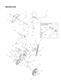
ModelSeries340 Thru345
13
12
</
\
k
33
35
23
\
1o
\
27
26
11
24
25
/
19
16'
19j
3
18
18
ModelSeries340 Thru345
Ref.
No.
Part No.
Ref.
No.
Part Description
Part No.
Part Description
1.
712-0392
746-0918
Forward Clutch Cable
736-3020
Hex L-Stop nut 1/4-28
Flat Wash.266" I.D.X.625" O.D.
22.
2.
23.
786-0053
Tine Shield Bracket
3.
710-0599
Hex Washer Screw 1/4-20 x.5"
24.
736-0171
4.
711-0920
Belt Cover Bolt
25.
712-0240
L-Wash. 7/16" I.D.
Hex Nut 7/16-20 Thd.
5.
712-04063
Hex Flange Top L-Nut 5/16-18
26.
710-0502A
Hex Washer Screw 3/8-16 x 1.25"
6.
710-0723
786-0145A
7.
756-0313
Hex Hd. Scr. 3/8-16 x 1.25" Lg.
Fl-ldler 2.12" O.D.
27.
28.
786-0039B
Engine Plate
Bracket Cover
8.
786-0149
736-0119
Lock Washer 5/16
786-0144
Idler Belt Keeper
Idler Bracket
29.
9.
30.
710-0107
Hex Bolt 5/16-24 x.5"
10.
712-0266
Hex Cent. Jam Nut 3/8-16 Thd.
31.
756-0971
Inner Engine Pulley Half
11.
786-0056
Belt Cover
32.
756-0972
12.
710-0599
Hex Washer Screw 1/4-20 x.5"
33.
736-0258
Outer Engine Pulley Half
Flat Washer.385 ID x 1.00D
13.
786-0035A
Tine Shield
34.
736-0169
Lock Washer 3/8
14.
710-3008
Hex Hd. Cap Scr. 5/16-18 x.75" Lg
35.
710-0191
Hex Bolt 3/8-24 x 1.25"
15.
712-04063
Hex Flange Top L-Nut 5/16-18
36.
736-0112
Bell-Wash.525"
16.
686-0091
37.
712-3029
Hex Jam Nut 1/2-20 Thd. (Gr. 5)
18.
714-0149B
Chain Case Assembly Complete
Internal Cotter Pin
38.
736-0312
Retainer Washer Bearing
19.
711-0415
Clevis Pin
39.
756-0585
FI-Pulley 6" Dia.
20.
642-0005
Outer Tine Assembly L.H.
40.
754-0428
V-Belt (Forward)
642-0004
Outer Tine Assembly R.H.
41.
750-0892
Spacer.64" Dia. x 2.4" Lg.
642-0003
Inner Tine Assembly L.H.
42.
748-0350
Pulley Mounting Adapter
642-0002
Inner Tine Assembly R.H.
21.
19
I.D. x 1.5" O.D.
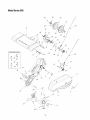
ModelSeries390
10
6
13
ttStandard
Briggs & Stratton
Tecumseh Engines
50
5O
16
15
531t
22
49
21 29
27
28
31
_,
\
32
_4
37
25
33
24
t
43
47
27
/
_46
__
2O
/
48
55
ModelSeries390
REF.
NO.
1.
PART NO.
712-0442
REF.
DESCRIPTION
NO.
PART NO.
DESCRIPTION
Acorn Lock Nut 1/4-20
30.
736-0242
Wash. Bell.340" I.D.x.872"
31.
711-1036A
I.D.x.630"
O.D.
O.D.
2.
736-3020
Flat Washer.271"
3.
720-0270A
32.
736-0119
Spec. Hex Nut
L-Wash. 5/16" I.D.
4.
731-1600
Reverse Handle Grip
Handle Cover w/o throttle
33.
710-3008
Hex Bolt 5/16-18 Gr. 5
5.
710-0779A
Truss Mach. Scr. #10 x 1/2" Lg.
34.
Cable Guide Bracket
6.
720-0274
35.
7.
712-3006
Handle Grip
Hex Nut 1/4-20 Gr.2
786-0129
710-0604A
36.
710-0602
8.
726-0135
Cap Speed Nut
37.
738-0934
Hex Wash. Hd. TT-Tap Scr.
Shdl. Bolt 5/16-18
9.
686-0083
Clutch Handle Assembly
38.
786-0138A
Frame (R.H.)
10.
720-0269
39.
786-0139A
11.
710-0641
40.
736-0171
Frame (L.H.)
Lock Washer 7/16
12.
731-1645A
Clutch Grip
Hex Bolt 1/4-20 x 2.25" Lg. Gr.5
Clutch Handle Holder
41.
13.
736-0140
Flat Washer.385"
I.D.x.62" O.D.
42.
712-0240
710-0176
14.
686-0014A
43.
712-0429
Hex Nylon Nut 5/16-18 Thd.
15.
736-0264
Reverse Handle Ass'y
Flat Washer.344" I.D.x.62" O.D.
46.
686-0081A
Wheel Hanger Bracket Assembly
734-1781
Wheel Ass'y 8" x 1.75"(Plastic)
734-1566
Wheel Ass'y 8" x 1.75" (Steel)
Shoulder Screw.496 I.D. x 1.445 O.D.
16.
649-04040
749-1401
Handle Assembly Comp.
Handle Brace t or tit
47.
19.
20.
736-0921
Lock Washer 1/2 t or tit
21.
710-3194
Hex Bolt 1/2-20 Gr. 5 t or tit
48.
49.
738-0929
750-0890
22.
786-0005
50.
23.
714-0149B
710-1236
749-0915A
24.
712-04063
25.
786-0003
26.
786-0004
27.
Depth Bar
Cotter Pin
51.
Hex Washer Screw 5/16-18 x.62" Lg.
Jam Nut 7/16-20 Gr. 2
Hex Bolt 5/16-18 x 2.75" Lg.
Spacer
Carr. Bolt 5/16-18 x 1
Engine Tube Brace (Std. B&S)
749-1082
Engine Tube Brace (Tec.)
52.
712-04063
Hex Flange L-Nut 5/16-18 Thd. tt
711-0415
Tail Piece Bracket (R.H.)
Clevis Pin
53.
54.
786-0159
736-0242
Engine Brkt. (Std. B&S)
Bell. Wash.34" I.D.
28.
710-0805
Hex Bolt 5/16-18 x 1.5" Lg.
55.
720-0195
Hand Knob
29.
710-0189
Hex Bolt 5/16-18 x 3" Lg.
56.
750-0470
Spacer
Hex Flange L-Nut 5/16-18 Thd. Gr.5
Tail Piece Bracket (L.H.)
t Briggs & Stratton Intek Engine
tt Standard Briggs & Stratton and Tec. Engine
ttt Honda Engine
21
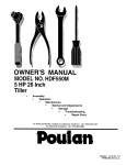
ModelSeries390
13
tttHonda Engine
44
\
43
\
1
19
2o
22
l
2
ModelSeries390
REF.
NO.
PART NO.
REF.
NO.
DESCRIPTION
1.
2.
3.
712-0392
736-3020
710-0599
4.
5.
711-0920
712-04063
6.
7.
8.
9.
10.
710-0723
756-0313
786-0149
786-0144
712-0266
Hex
Flat
Idler
Idler
Hex
11.
13.
14.
16.
17.
786-0057
786-0043A
710-3008
686-0091
686-0106
Belt Cover
Tine Shield
18.
714-0149B
19.
20.
Clevis Pin
21.
711-0415
642-0023
642-0024
642-0003
22.
642-0002
746-0918
Inner Tine Assembly R.H.
Forward Clutch Cable
23.
24.
25.
746-0953
756-0585
750-0892
Reverse Clutch Cable
Hex L-Stop nut 1/4-28
Flat Wash.266" I.D.x.625"
26.
27.
28.
29.
30.
31.
32.
33.
34.
35.
36.
38.
42.
43.
44.
45.
46.
47.
48.
49.
50.
51.
52.
53.
54.
O.D.
Hex Washer TT-Tap Scr. 1/4-20 x.5"
Belt Cover Bolt
Hex Flange Top L-Nut 5/16-18 (Gr.5)
Hd. Scr. 3/8-16 x 1.25" Lg. (Gr.5)
Idler Pulley 2.12" O.D.
Belt Keeper
Bracket
Cent. Jam Nut 3/8-16 Thd.
Hex Hd. Cap Scr. 5/16-18 x.75" Lg
Chain Case Assembly Complete
Outer Disc Plate Assembly
Internal Cotter Pin
Outer Tine Assembly L.H.
Outer Tine Assembly R.H.
Inner Tine Assembly L.H.
FI-Pulley 6" Dia.
Spacer.64" Dia. x 2.4" Lg.
PART NO.
748-0350
736-0112
712-3029
732-0697
786-0040B
736-0119
710-0237
756-0971
756-0600
736-0452
710-0152
686-0013
786-0041
710-0502A
786-0145A
786-0053
736-0171
712-0240
754-0428
754-0429
738-0102
738-0930
710-0805tff
712-3010tff
736-0242tit
1-1-1Honda Engine
23
DESCRIPTION
Pulley Mounting Adapter
Bell-Wash.525" I.D. x 1.5" O.D.
Hex Jam Nut 1/2-20 Thd. (Gr. 5)
Return Spring
Reverse Bracket
Lock Washer 5/16
Hex Bolt 5/16-24 x.625"
Engine Inner Half Pulley
Reverse Engine Pulley
Bell Washer.396" I.D. x 1/14" O.D.
Hex Bolt 3/8-24 x 1.00"
Reverse Arm Assembly
Reverse Belt Keeper
Hex L-Wash. TT-Tap 3/8-16 x 1.25"
Engine Plate
Tine Shield Bracket
L-Wash. 7/16" I.D.
Hex Nut 7/16-20 Thd.
V-Belt (Forward)
V-Belt (Reverse)
Shld. Screw.498
Shld. Screw.560
Screw 5/16-18 x
Hex Nut 5/16-18
Bell Washer
1/2 x 41.9"
3/8 x 45.68"
x 1.445
x. 165
1.50
MANUFACTURER'S
LIMITED WARRANTY
The limited warranty set forth below is given by MTD LLC with
respect to new merchandise purchased and used in the
United States, its possessions and territories.
"MTD"warrants this product against defects in material and
workmanship for a period of two (2) years commencing on the
date of original purchase and will, at its option, repair or
replace, free of charge, any part found to be defective in
materials or workmanship. This limited warranty shall only
apply if this product has been operated and maintained in
accordance with the Operator's Manual furnished with the
product, and has not been subject to misuse, abuse,
commercial use, neglect, accident, improper maintenance,
alteration, vandalism, theft, fire, water, or damage because of
other peril or natural disaster. Damage resulting from the
installation or use of any part, accessory or attachment not
approved by MTD for use with the product(s) covered by this
manual will void your warranty as to any resulting damage.
Normal wear parts are warranted to be free from defects in
material and workmanship for a period of thirty (30) days from
the date of purchase. Normal wear parts include, but are not
limited to items such as: batteries, belts, blades, blade
adapters, grass bags, rider deck wheels, seats, snow thrower
skid shoes, shave plates, auger spiral rubber and tires.
HOW TO OBTAIN SERVICE: Warranty service is available,
WITH PROOF OF PURCHASE, through your local authorized
service dealer. To locate the dealer in your area, check your
Yellow Pages, or contact MTD LLC at P.O. Box 361131,
Cleveland, Ohio 44136-0019, or call 1-800-800-7310 or 1330-220-4683 or log on to our Web site at
www.mtdproducts.com.
This limited warranty does not provide coverage in the
following cases:
a.
b.
c.
d.
The engine or component parts thereof. These items
may carry a separate manufacturer's warranty. Refer
to applicable manufacturer's warranty for terms and
conditions.
Log splitter pumps, valves, and cylinders have a
separate one year warranty.
Routine maintenance items such as lubricants, filters,
blade sharpening, tune-ups, brake adjustments, clutch
adjustments, deck adjustments, and normal
deterioration of the exterior finish due to use or
e,
f,
g.
FOR:
MTD does not extend any warranty for products sold or
exported outside of the United States, its possessions
and territories, except those sold through MTD's
authorized channels of export distribution.
Replacement parts that are not genuine MTD parts.
Transportation charges and service calls.
No implied warranty, including any implied warranty of
merchantability of fitness for a particular purpose,
applies after the applicable period of express written
warranty above as to the parts as identified. No other
express warranty, whether written or oral, except as
mentioned above, given by any person or entity,
including a dealer or retailer, with respect to any product,
shall bind MTD. During the period of the warranty, the
exclusive remedy is repair or replacement of the product
as set forth above.
The provisions as set forth in this warranty provide the
sole and exclusive remedy arising from the sale. MTD
shall not be liable for incidental or consequential loss or
damage including, without limitation, expenses incurred
for substitute or replacement lawn care services or for
rental expenses to temporarily replace a warranted
product.
Some states do not allow the exclusion or limitation of
incidental or consequential damages, or limitations on how
long an implied warranty lasts, so the above exclusions or
limitations may not apply to you.
In no event shall recovery of any kind be greater than the
amount of the purchase price of the product sold. Alteration
of safety features of the product shall void this warranty.
You assume the risk and liability for loss, damage, or injury to
you and your property and/or to others and their property
arising out of the misuse or inability to use the product.
This limited warranty shall not extend to anyone other than the
original purchaser or to the person for whom it was purchased
as a gift.
HOW STATE LAW RELATES TO THIS WARRANTY: This
limited warranty gives you specific legal rights, and you may
also have other rights which vary from state to state.
IMPORTANT:Owner must present Original Proof of
Purchase to obtain warranty coverage.
exposure.
Service completed by someone other than an
authorized service dealer.
MTD LLC, P.O.BOX361131CLEVELAND,OHIO44136-0019; Phone:1-800-800-7310,1-330-220-4683