1
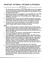
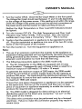
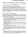
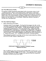
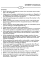
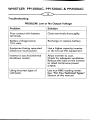
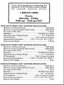
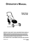
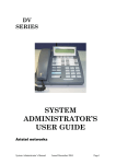
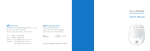
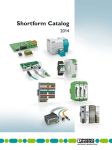
OWNER’S MANUAL
PPIOOOAC, PPI 500AC
& .PP2500AC
HIGH SURGE POWER INVERTERS
WHISTLER
ENHANCED
DRIVING
TOOLS
WHISTLER PPIOOOAC, PPI500AC & PP2500AC
Welcome To WHISTLER.
For over 30 years, WHISTLER CORPORATION has been manufacturing a
wide range of products designed to make your driving experience safer,
more comfortable and more enjoyable.
Included in the WHISTLER line is a special selection of products we call
“Enhanced Driving Tools.” These products range from portable jump
start systems to high intensity flashlights to radar detectors and are
designed to keep you
IN TOUCH
e
IN COMFORT
•
IN CONTROL
A Word About WHISTLER Inverters.
WHISTLER manufactures a complete line of DC to AC inverters ranging
in capacity from 50 Watts to 2500 Watts. These inverters offer advanced
technology, dependable operation and will provide years of reliable
service when used in accordance with our operating instructions.
WHISTLER inverters convert low voltage, direct (DC) current to 110 volt alternating (AC) household current Depending on the model and its rated capacity,
WHISTLER inverters draw power either from standard 12 volt automobile and
marine batteries or from portable high power 12 volt sources.
Certain models in the WHISTLER inverter line operate indirectly through
an adapter which plugs into the cigarette lighter socket in your car, truck
or boat. Other models, including the WHISTLER 1000, 1500 and 2500
are designed to be hard wired directly to the 12 volt power source.
Important Information About Your New WHISTLER Inverter.
This manual will provide you with directions for the safe and efficient
operation of your WHISTLER 1000 Watt, 1500 Watt or 2500 Watt In—
verter. Read the manual carefully before using your inverter and keep
the manual on file for future reference.
Note:
• Your WHISTLER inverter is designed to operate from a 12 volt power
source only. Never attempt to connect the inverter to any other
power source including any AC power source.
• 110 Volts of current can be lethal. Improper use of your inverter may
result in property damage, personal injury or loss of life.
OWNER’S MANUAL
Getting Off To A Good Start
Power equipment and appliances which operate with motors or tubes
require an initial surge of power to get them up and running. This power
surge is referred to as the “starting load” or “peak load.” (By comparison,
devices such as standard light bulbs do not require a starting load). Once
the equipment or appliance has been powered up, it settles down to a
slower pace and requires far less electrical power to operate. This lower
power requirement is referred to as the “continuous load.”
In order to ensure that the capacity of your WHISTLER inverter is sufficient to meet the required start up load, you must first determine the
power consumption of the equipment or appliance you plan to operate.
Power consumption is rated either in wattage or in amperes and information regarding the required “watts” or “amps” generally is stamped
or printed on most appliances and equipment. If this information is not
indicated on the appliance or equipment, check the owner’s manual or
contact the manufacturer.
Ifthe power consumption is rated in amps, multiply the number of amps
by 110 (AC voltage) to determine the comparable wattage rating. As a
general rule, you can determine the required start up load by multiplying the wattage rating by 10. It is the start up load of the equipment or
appliance you plan to operate that will determine whether or not your
inverter has the required capacity to power it.
For further information on the fundamental operating principles of
inverters and related data, see “For You Technical Types.”
Don’t Push It.
Although your WHISTLER inverter has the capacity to provide power
output (excess current) equal to approximately two times its rated
wattage capacity for a very brief period, it is designed to operate equipment and appliances with start up load wattage ratings no higher than
its own maximum continuous wattage rating.
For example, the 1500 model has a maximum continuous rating of 1500
watts. Although this model has the capacity to briefly provide up to 3000
watts of power (that is, excess current), it is designed to operate equipment and appliances with start up load requirements of 1500 watts or less.
Consequently, if the start up load rating of your equipment or appliance
is the same or approximately the same as the maximum continuous
rating of the inverter, the inverter may not have the capacity to provide
the required start up load.
WHISTLER PPIOOOAC, PPI500AC & PP2500AC
cdZ~
To determine whether your inverter will operate a particular piece of
equipment or appliance, run a test. The inverter is designed to automatically shut down in the event of a power overload and testing equipment and appliances with start up load ratings comparable the maximum wattage rating of the inverter will not damage it.
Some refrigerators, freezers, pumps and other similar equipment and
appliances require very high start up loads to operate. Before attempting to power up this type of equipment or appliance, make especially
certain that all connections have been properly made and that the
power source is fully charged.
Once those conditions have been checked, turn the inverter switch ON
and monitor the Battery Voltage Indicator (See “Operating Guidelines &
Safety Features). If the Voltage Indicator confirms that the input voltage
is in the acceptable range, turn the inverter switch OFF, ON, OFF, and
ON again in quick succession. If this procedure is unsuccessful, it is likely
that the inverter does not have the required start up capacity to operate
the equipment or appliance in question.
If the Voltage Indicator reading falls below 11 volts during the start up process, a battery with greater CCA (“Cold Cranking Amps”) may be required.
Operating Guidelines & Safety Features.
Important Note: Each of the following operating procedures and safety
features must be carefully reviewed and thoroughly understood prior to
using the inverter. Failure to do so may result in damage to the inverter
or equipment or serious personal injury
WHISTLER PP1 OQOAC & PP1 500AC
Front View
a). ON/OFF Switch. This switch controls the flow of power from the
power source to the inverter. It does not control the power running
from the inverter to the equipment or appliance being operated.
OWNER’S MANUAL
cz~
b). High Temperature LED Indicator Light. This light will turn RED and
the inverter will automatically shut down when the internal temperature exceeds design parameters for safe operation. When this
occurs, turn the equipment or appliance off.
In the event of excess temperature, the High Speed Cooling Fan also
will automatically turn on. Overheating may result when the inverter
is being operated at levels exceeding its wattage rating or because it
has been placed in a location or in an manner which prevents proper
heat dissipation. After approximately 15 minutes, the High Temperature Indicator light and the Cooling Fan will turn off and the inverter
will automatically restart indicating that the inverter temperature has
dropped to a safe operating level.
c). Over Load LED Indicator Light. This light will turn RED and the
inverter will automatically shut down when the continuous power
draw from the inverter exceeds the maximum continuous power
rating for the inverter. Turn the inverter OFF (0), determine and
resolve the cause of the overload prior to resuming operation of the
equipment or appliance. Turning the inverter ON (I) will reset it.
d). Battery Current & Voltage Bar Graph Meters (GREEN, YELLOW RED).
Current Indicator. This illuminated Bar Graph monitors the current
being drawn from the battery by the inverter. Depending on the
amount of current being drawn, the Bar Graph reading generally will
be in the GREEN or YELLOW zone.
When the reading rises to the RED zone, the invertermay automaticallyshut
down. In this event, it is likely that the draw ofthe equipment or appliance
being operated is greater than the battery is capable of producing.
Voltage Indicator. This Bar Graph displays the voltage being drawn
from the battery by the inverter. The voltage is measured at the Negative and Positive power input terminals on the inverter. At “low voltage
input,” the voltage level reading will approximate the battery voltage.
At “high voltage input,” the voltage level reading will be lower than the
battery voltage due to the voltage “drop” that occurs as the battery
voltage runs through the terminal connections and cables.
The inverter is designed to operate with input voltages ranging from
10 to 15 volts of direct current (DC). When the voltage drops below
10.5 volts DC, the voltage indicator will register in the lower RED zone
and an audible alarm will sound. If the voltage drops below 10
volts DC, the voltage indicator will go out and the inverter will
automatically shut down.
The inverter also will shut down automatically when the input voltage
WHISTLER PPI OOOAC, PPI 500AC & PP2500AC
~Z)
exceeds 15 volts DC. Despite this “built in” protection, the inverter may be
damaged if the input voltage exceeds 15 volts DC and damage caused by
excess voltage input is not covered under the WHISTLER warranty.
Under optimum conditions, the voltage reading will be in the GREEN zone.
Note:
• In the event of automatic shut down or continuous audible alarm,
turn the inverter OFF (0) until the source of the related problem has
been determined and resolved.
e). Two Standard North American 110 AC Outlets are provided.
f). Remote Operation Socket.
The inverter is designed to be
f
operated from a remote location via
the WHISTLER PPO15DC Remote
Control Switch which plugs into this
socket. This optional accessory is
Bottom View
available through WHISTLER or your WHISTLER dealer.
j
WHISTLER PP1 OOOAC & PP1 500AC Inverter
Rear View
i). High Speed Cooling Fan. This fan will turn on automatically when the
internal temperature exceeds design parameters for safe operation.
The Cooling Fan will automatically turn off when the temperature drops
to a safe operating level. This fan does not run continuously.
j). Power Input Terminals (WHITE/Negative, RED/Posftive).
(IMPORTANT: The Negative Terminal on the 2500 model is BLACK. See
opposite).
k). Chassis Ground Terminal Lug.
Note:
• The 2500 model inverter incorporates all of the operating and safety
features of the 1000 and 1500 models. In addition to these common
features, the WHISTLER 2500 is equipped with circuit breakers and a
OWNER’S MANUAL
terminal for making a direct connection between the inverter and an
electrical distribution panel.
WHISTLER PP2500AC Inverter
Front View
a).
b).
c).
d).
e).
f).
g).
ON/OFF Switch.
High Temperature LED Indicator Light.
Over Load LED Indicator Light.
Battery Current & Voltage Bar Graph Meters.
Twin Standard North American 110 AC Outlets.
Remote Operation Socket.
Circuit Breakers. (2500 Model Only). Each 110 AC outlet is
equipped with a 15 amp circuit breaker.
h). “Direct Wire” Connection. (2500 Model Only). This terminal is
utilized for direct connection to an electrical distribution panel. This
connection is to be made only by a licensed electrician. See Notes
in the following section, “Making The Connection”).
-I--i
k
WHISTLER PP2500AC Inverter
Rear View
WHISTLER PPIOOOAC, PPI500AC & PP2500AC
i). High Speed Cooling Fan.
Power Input Terminals. (BLACK/Negative, RED/Positive).
(IMPORTANT: The Negative terminal on the 1000 and 1500 models
is WHITE. See previous page).
k). Ground Terminal Lug.
j).
Selecting The Optimum Power Source.
Operating the inverter for extended periods combined with a high
continuous load demand may result in excessive power drain from the
battery. Therefore, the reserve capacity of the battery you select to
power the inverter is an important consideration.
The potential power drain can be estimated by calculating the reserve
power (“amp/hour”) of the battery and the amps required by the inverter to meet the continuous load demand of the equipment or appliance being operated.
1. To calculate the amp/hour ofthe battery, first determine its “reserve
minutes” rating. (Deep cycle marine batteries generally have the highest
reserve minute ratings). This rating typically is marked on the battery
along with the “Cold Cranking Amps” (CCA) rating. Multiply the reserve
minutes rating of the battery by 0.3 to determine the battery amp/hour.
A battery with a reserve minutes rating of 166 has an amp/hour
rating of 50 (166 x 0.3 = 49.8).
2. To estimate the maximum battery power the inverter will require to
run a piece of equipment or appliance, divide its continuous load
wattage requirement by 10.
The WHISTLER 1000 utilizes 50 amps of battery power to operate an
appliance with a 500 watt continuous load requirement. (500 +10 = 50).
3. Conclusion: The reserve power of the battery is sufficient to satisfy
the continuous load demand placed on the inverter for a maximum
of about one hour. (49.8 + 50 = 1 hour).
Note:
• When the inverter will be operating equipment or appliances with
high continuous load ratings for extended periods, it is not advisable
to power the inverter with the same battery used to power your car
or truck. If the car or truck battery is utilized for an extended period,
it is possible that the battery voltage may be drained to the point
where the battery has insufficient reserve power to start the vehicle.
OWNER’S MANUAL
•
It may be advisable to operate the inverter from a bank of batteries
of the same type in a “parallel” configuration. Two such batteries
will generate twice the amp/hours of a single battery; three batteries
will generate three times the amp/hours and so on.
This multiple parallel battery option is especially recommended for
the WHISTLER 2500 due to the high level of amps this model requires to produce 2500 watts of continuous load.
Wire Cable Gauges.
For safe and proper operation ofthe inverter, connect the inverter tothe power
source with the thickest wire available and in the shortest length practical.
1000 & 1500 Models.
When the inverter and the battery are set up within four feet of each
other, use a minimum of # 4 gauge wire to make the connections.
Within four to six feet, use a minimum of # 2 gauge wire. At distances of more than six feet, use # 0 gauge wire.
Regardless of the wire gauge selected to make the connections to
the battery, we recommend use of an “0 Ring Adapter.” Use of #0
gauge wire to make the connections to the inverter may require a “0
to 4 Gauge Adapter.” Both adapters are available through electronic
supply stores including Radio Shack. Radio Shack part numbers are
as follows:
O Ring Adapter:
RSU1 1538139
0-4 Gauge Adapter:
RSU1 1539667
2500 Model.
When the inverter and the battery are set up within four feet of each
other, use a minimum of # 2 gauge wire to make the connections.
Within four to six feet, use a minimum of # 0 gauge wire. At distances of more than six feet, use two # 0 gauge wires connected in
parallel to the battery. This connection will require eight 0 Ring
Adapters as referenced above. Alternatively, use # 00 (2/0) gauge
wire with the appropriate adapters. These # 00 gauge wire adapters
are available through most electronic supply stores.
Making The Connection.
1. Make certain the inverter power switch is in the OFF position.
2. Connect one wire each to the Negative and Positive terminals at the
rear of the inverter and tighten the screws to make a secure connection. Do not over tighten these screws.
WHISTLER PPIOOOAC, PPI500AC & PP2500AC
cdI~
(To make these connections on the 2500 model, remove the supplied
nut at each terminal on the inverter, install the wire connectors flush
with the metal backing plates and refasten the nuts securely. Do not
overtighten these nuts).
3. Connect the wire from the Negative (—) terminal (WHITE on the 1000,
1500 models, BLACK on the 2500 model) on the inverter to the
Negative (—) terminal on the 12 volt power source. Make certain the
connection is secure.
4. Confirm that the wire you have just installed is properly connected.
(Specifically, make certain that the wire is connected to the Negative
(—) terminals on both the inverter and the 12 volt power source).
5. Connect the wire from the Positive (+) terminal (RED on all three
models) on the inverter to the Positive (—) terminal on the power
source. Make certain that the connection is secure.
Note:
• Failure to make a proper connection between the inverter and the
power source will result in reverse polarity. Reverse polarity will blow
the internal fuses in the inverter and permanently damage the inverter. Damage caused by reverse polarity is not covered under the
WHISTLER warranty.
• Loose connections can result in a severe decrease in voltage which
may cause damage to the wires and insulation.
• The audible alarm may make a momentary “chirp” when the inverter is
being connected to or disconnected fromthe power source. This is normal.
• Making the connection between the Positive terminals may cause a
spark as a result of current flowing to charge capacitors within the
inverter. This is a normal occurrence. Due to the possibility of
sparking, however, it is extremely important that both the inverter
and the 12 volt battery be well removed from any possible source of
flammable fumes or gases.
Failure to heed this warning could result in fire or explosion.
6. Run a ground from the Ground Lug Terminal at the rear of the inverter
to a proper grounding point using the shortest practical length of 8
AWG wire. Selection of the grounding point will depend on where
you are using the inverter. The ground wire may be connected to the
chassis of your vehicle or to the grounding system in your boat or to
the earth if you are operating the inverter in a remote location. Before
connecting the ground, make certain that the inverter is turned off.
Operating the inverter without properly grounding it may result in
electrical shock.
OWNER’S MANUAL
7. Turn the inverter ON (I). Check the Bar Graph Meter on the front panel.
The Voltage Bar Graph should read between 11 and 14 volts depending
on the voltage of the power source. If the reading is not within this range,
check the voltage of the powersource and the terminal connections on
the power source and the inverter to make sure they are secure.
Neither the High Temperature or Over Load LED Indicators should
be lighted.
8. Turn the inverter OFF (0). The High Temperature and Over Load
Indicators may “blink” briefly. This is normal. Also, the internal
audible alarm may make a momentary “chirp.” This is normal.
9. Confirm that the equipment or appliance to be operated is turned
off. Plug the equipment or appliance into one of the two AC receptacles on the front panel of the inverter.
10. Turn the inverter on. Turn the equipment or appliance on.
Note:
• The use of an extension cord from the inverter to the appliance or
equipment being operated will not significantly decrease the power
being generated by the inverter. For best operating results, the
extension cord should be no more than 50 feet long.
• The following precautions apply to the 2500 model only.
a). The AC receptacles on the 2500 are equipped with 15 amp
circuit breakers. Consequently, each of these outlets is rated for a
maximum output of 1500 watts (110 volts x 15 amps).
To generate the maximum output of 2500 watts, the 2500 model
should be connected to a power supply which has the capacity to
produce 250 amps. The loads should be distributed between the
two receptacles to ensure that each outlet is producing no more than
its maximum 1500 watt output.
If more than one piece of equipment or appliance is to be operated
at the same time, first turn on the inverter and then turn on each
piece of equipment or appliance separately to enable the inverter to
produce the required start up loads.
b). The 2500 model is designed for direct wiring to an electrical
distribution panel via the direct wire connection “cut out” on the
front panel of the inverter.
This direct wire connection must be performed only by a licensed
electrician. Failure to make this connection properly may result in
severe injury.
WHISTLER PPIOOOAC, PPI500AC & PP2500AC
You’ll Get A Charge Out Of This. (Or Maybe Not).
Using the inverter to recharge charging units associated with such equipment as portable power tools, flashlights, video cameras and laptop
computers may cause damage to the inverter or the charging unit.
Although we advise against it, if you attempt to recharge a charging
unit, monitor the temperature of the charging unit for approximately 10
minutes. If the charging unit become unusually warm, disconnect it from
the inverter immediately.
For You Television Fans & Audiophiles.
Although the inverter is shielded and filtered to minimize signal interference, some interference with your television picture may be unavoidable, especially with weak signals. However, here are some suggestions
that may improve the reception.
1. First, make certain that the television antenna produces a clear signal
under normal operating conditions (i.e., at home plugged into a
standard 110 AC wall outlet). Also, ensure that the antenna cable is
properly shielded and of good quality.
2. Change the relative positions of the inverter, antenna cables and
television power cord.
3. Isolate the television, its power cord and antenna cables from the 12
volt power source by running an extension cord from the inverter to
the television set.
4. Coil the television power cord and the input cables running from the
12 volt power source to the inverter.
5. Attach a “Ferrite Data Line Filter” to the television power cord.
More than one filter may be required. These filters are available at
most electronic supply stores including Radio Shack. (Radio Shack
Part Number 273-105).
Note:
• Inexpensive sound systems may emit a “buzzing” sound when operated with the inverter. This is due to inadequate filters in the sound
system. There is no solution to this problem short of purchasing a
sound system with a higher quality power supply.
OWNER’S MANUAL
For You Microwave Chefs.
The power rating commonly associated with microwave ovens is the
“cooking power” which is the power being “delivered” to the item
being microwaved. The actual operating power requirement rating is
higher than the cooking power rating and typically is referenced on the
back of the microwave. If the operating power requirement does not
appear on the back of the microwave, check the owner’s manual or
contact the manufacturer.
For You Technical Types.
I. Basic Operating Principles.
Inverters work in two stages. During the first stage, the DC to DC
converter increases the DC input voltage from the power source (e.g.
a 12 volt battery) to 145 volts DC. In the second stage, the high
voltage DC is converted to 110 volts (60 Hz AC), using advanced
power MOSFET transistors in a full bridge configuration. The result
is excellent overload capability and the capacity to operate difficult
reactive loads. The output waveform resulting from this conversion is
a “quasi-sine wave” or a modified sine wave” as shown below.
This stepped waveform is similar to the power generated by utilities
and has a broad range of applications.
WHISTLER PP1000AC, PP1 SOQAC, PP2500AC Inverter
Modified Sine Wave
The modified sine wave produced by WHISTLER inverters has a root
mean square (RMS) voltage of 110 volts. The majority of AC voltmeters are calibrated for RMS voltage and assume that the measured
waveform will be a pure sine wave.
WHISTLER PPI OQOAC, PP1 500AC & PP2500AC
Consequently, these meters will not read the RMS modified sine wave
voltage correctly and, when measuring the inverter output, the
meters will read about 20 to 30 volts too low. To accurately measure
of the output voltage of the inverter, use a true RMS reading voltmeter such as a Fluke 87, Fluke 8060A, Beckman 4410, Triplett 4200 or
any multimeter identified as ‘True RMS.”
Some Powerful Advice.
The inverter will work best when placed on a reasonably flat surface.
The floor of your car or truck is an acceptable location as long as the
area is dry and well ventilated.
To maintain the inverter in proper working condition, note the following
important safety precautions:
• MOISTURE. Keep the inverter dry. Do not expose it to moisture.
Do not operate the inverter if you, the inverter the device being
operated or any other surfaces that may come in contact with any
power source are wet. Water and many other liquids can conduct
electricity which may lead to serious injury or death.
• HEAT. The ambient air temperature should be between 50” and 800
F. Avoid placing the inverter on or near heating vents, radiators or
other sources of heat. Do not place the inverter in direct sunlight.
•
•
VENTILATION. In order to properly disperse heat generated while the
inverter is in operation, keep it well ventilated. While in use, maintain
several inches of clearance around the top and sides of the inverter.
FUMES & GASES. Avoid using the inverter near flammable materials. Do not place the inverter in areas such as battery compartments
where fumes or gases may accumulate.
OWNER’S MANUAL
In Review.
• Never attempt to operate the inverter from any power source other
than a 12 volt battery.
• Always ensure the power cable terminal connections run Negative (—)
to Negative (-.) and Positive (+) to Positive (+). Check these connections frequently to ensure they are secure.
• Use the heaviest gauge wire available to connect the inverter to the
power source.
• While connecting the inverter to the power source, make certain that
the inverter is well removed from any potential source of flammable
fumes or gases.
• Direct connection of the 2500 model inverter to a distribution panel
is to be made by a licensed electrical only.
• Always ground the inverter before operating it.
• Make certain the power consumption of the appliance or equipment
you wish to operate is compatible with the capacity of the inverter.
• If the rated power consumption of the equipment is in the range of
the rated capacity of the inverter, test the inverter to ensure that it
will operate properly.
• When attempting to recharge battery chargers, monitor the temperature of the battery charger for approximately 10 minutes. If the
battery charger becomes abnormally warm, disconnect it from the
inverter immediately.
• When operating the inverter with an automobile or marine battery,
start the engine every 30 to 60 minutes and let it run for approximately 10 minutes to recharge the battery.
• In the event a continuous audible alarm or automatic shut off, turn
the inverter OFF immediately. Do not restart the inverter until the
source of the problem has been identified and corrected.
• Always disconnect the inverter when not in use.
• Do not expose the inverter to moisture.
• Avoid placing the inverter near sources of heat or in direct sunlight.
• When in use, make certain the inverter is properly ventilated.
• Always operate the inverter in accordance with the instructions in
this manual. Failure to do so may result in property damage, personal injury or loss of life.
WHISTLER PPIOOOAC, PPI500AC & PP2500AC
Troubleshooting
PROBLEM: Low or No Output Voltage
Problem
Solution
Poor contact with battery
terminals.
Clean terminals thoroughly.
Battery voltage below
10.5 volts.
Recharge or replace battery.
Equipment being operated
draws too much power.
Use a higher capacity inverter
or do not use this equipment.
lnverter is too hot (thermal
shutdown mode.)
Allow inverter to cool.
Check for adequate ventilation.
Reduce the load on the inverter
to rated continuous power
output.
Using incorrect type of
voltmeter.
Use true RMS reading meter.
See “For You Technical Types”
Section of this manual.
OWNER’S MANUAL
PROBLEM:
LOW
Battery Alarm On All The Time
Problem
Solution
Input voltage below 10.5 volts.
Keep input voltage above 10.5
volts to maintain regulation.
Poor or weak battery condition. Replace battery.
Inadequate power being
delivered to the inverter or
excessive voltage drop.
Use lower gauge wire.
See “Wire Cable Gauges”
Section of this manual. Keep
wire length as short as possible.
PROBLEM: TV Interference
Problem
Solution
Electrical interference from
inverter.
Add a Ferrite data line filter on
to the TV power cord.
See the “For You Television
Fans and Audiophiles” Section
of this manual.
ConsumerWarranty
Your Whistler product is warranted to the original purchaser for a period of three years
from the date of original purchase against all defects in materials and workmanship.
This limited warranty is void if the unit is abused, modified, installed improperly, if the
housing has been removed, or if the serial number is missin~,• There are no express
warranties covering this product otherthan those set forth in t is warranty. All express
or implied warranties for this product are limited to three years. Whistler is not liable
for damages of any type arising from the use, misuse, or operation ofthis product.
Service Under Warranty
During the warranty period, defective units will be repaired or replaced (with the same
or a comparable model), at Whistler’s option, without charge to the purchaser when
returned prepaid, with dated proof of purchase to the address below. Units returned
without dated proof of purchase will be handled as described in section “Service Out
Of Warranty.” There are no authorized service stations for Whistler brand products
otherthan the factory.
When returning a unit for service under warranty, please follow these instructions:
1. Ship the unit in the original carton or in a suitable sturdy equivalent, fully insured,
with return receipt requested, and shipping charges prepaid to:
Whistler CTS
16 Elizabeth Drive
Chelmsford, MA 01824
IMPORTANT: Whistler will not assume responsibility for loss or damage incurred in
shipping. Therefore, please ship your unit insured with return receipt requested.
2. Include with your unit the following information, clearly printed:
• Your name and street address (for shipping via UPS), and a daytime telephone
number. (No RO. Box please.)
• A detailed description of the problem (e.g., “Unit powers up without any warning
lights but does not power anything. “).
• A copy of your dated proof of purchase or bill of sale.
3. Be certain your unit is returned with its serial number. For reference, please write
your unit’s serial number in the following space: s/n ____________________________
Units without serial numbers are not covered under warranty.
IMPORTANT: To validate that your unit is within the warranty period, make sure you
keep a copy of your dated proof of purchase.
Service Out Of Warranty
Units will be repaired at “out of warranty” service rates when:
• The unit’s original warranty has expired.
• Dated proof of purchase is not supplied.
• The unit has been returned without its serial number.
•The unit has been abused, modified, installed improperly, or had its housing removed.
The minimum out of warranty service fee for your Whistler product is $55.00 (U.S.). If
you require out of warranty service, please return your unit as outlined in the section
“Service Under Warranty” along with a certified check or money order for $55.00.
Paymentmay also be made by MasterCard or VISA; personal checks are not accepted.
In the event repairs cannot be covered by the minimum $55.00 service fee, you will be
contacted by a Whistler technical service specialist, (by mail or telephone), who will
outline options available to you. If you elect not to have your unit repaired/replaced, it
will be returned to you along with your certified check or money order.
IMPORTANT: When returning your unit for service, be certain to include a daytime
telephone number.
Customer Service
If you have questions concerning the operation of your Whistler product, or require
service during or after the warranty period, please call Customer Technical Service at
1-800-531-0004. Representatives are available toanswer your questions Monday - Friday
from 9:00 a.m. to 5:00 p.m. (EST).
If you have questions Concerning the
operation of this Whistler product please
call customer technical service:
1-800-531-0004
Hours:
Monday Friday
9:00 am 5:00 pm EST
-
-
WHISTLER PP1000AC WATT INVERTER SPECIFICATIONS
Maximum Continuous Power
1000 Watts
Maximum Surge Capability (Peak Power)
2000 Watts
No Load Current Draw
<0.32 A
Waveform
Modified Sine Wave
Operating Input Voltage Range
10 - 15 Volts DC
AC Receptacle
Dual 3 Prong Grounded
Approximate Dimensions
3.25” H x 10.25” W x 13.50” L
Approximate Weight
7.25 lbs
WHISTLER PPI 500AC WATT INVERTER SPECIFICATIONS
Maximum Continuous Power
1500 Watts
Maximum Surge Capability (Peak Power)
3000 Watts
No Load Current Draw
<0.37 A
Waveform
Modified Sine Wave
Operating Input Voltage Range
10 - 15 Volts DC
AC Receptacle
Dual 3 Prong Grounded
Approximate Dimensions
3.25” H x 10.25” Wx 18.50” L
Approximate Weight
10 lbs
WHISTLER PP2500AC WATT INVERTER SPECIFICATIONS
Maximum Continuous Power
2500 Watts
Maximum Surge Capability(Peak Power)
4500 Watts
No Load Current Draw
<0.6 A
Waveform
Modified Sine Wave
Operating Input Voltage Range
10 - 15 Volts DC
AC Receptacle
Dual 3 Prong Grounded
Approximate Dimensions
6.5” H x 9.0” W x 19.0” L
Approximate Weight
19 lbs
WHISTLER CORPORATION
16 ELIZABETH DRIVE, CHELMSFORD, MA 01824
CUSTOMER TECHNICAL SERVICE TEL. 800/531-0004
WHISTLER 1997