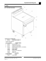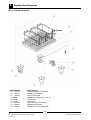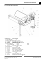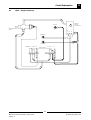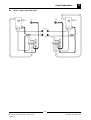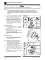
1
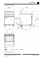
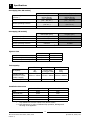
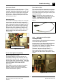
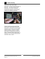
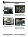
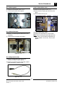
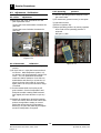
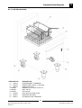
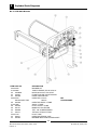
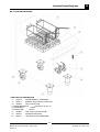
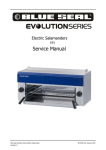
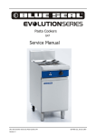
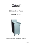
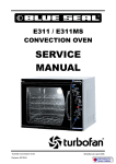
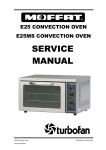
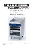
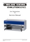
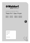
Gas Fryers
GT45 / GT46 / GT60
Service Manual
1
Blue Seal Evolution Series GT45 / GT46 / GT60
Revision 1/
© Moffat Ltd, January 2007
WARNING:
ALL INSTALLATION AND SERVICE REPAIR WORK MUST BE CARRIED OUT BY
QUALIFIED PERSONS ONLY.
IMPORTANT: MAKING ALTERATIONS MAY VOID WARRANTIES AND APPROVALS.
2
Blue Seal Evolution Series GT45 / GT46 / GT60
Revision 1/
© Moffat Ltd, January 2007
Contents
This manual is designed to take a more in depth look at the GT45, GT46 and GT60 gas fryers for the purpose of making the units more understandable to service people.
There are settings explained in this manual that should never require to be adjusted, but for completeness
and those special cases where these settings are required to change, this manual gives a full explanation
as to how, and what effects will result.
Section
Page Number
1. Specifications............................................................................................1
2. Installation................................................................................................5
3. Operation...................................................................................................9
3.1 Description
of Controls
3.2
Explanation of Control System - Single Tank Fryers
3.3
Explanation of Control System - Twin Tank Fryers
4.
Cleaning and Maintenance......................................................................13
5. Trouble-shooting Guide...........................................................................15
5.1 Trouble-shooting
5.2 Fault
Diagnosis
6. Service
Chart
Procedures..................................................................................21
6.1 Access
6.2 Replacement
6.3 Adjustment
/ Calibration
7. Accessories..............................................................................................29
8. Replacement Parts .................................................................................30
8.1 GT45
8.2 GT46
8.3 GT60
9. Circuit
Schematics...................................................................................41
10. Service Contacts......................................................................................44
Appendix A: Gas Type Conversion.................................................................46
3
Blue Seal Evolution Series GT45 / GT46 / GT60
Revision 1/
© Moffat Ltd, January 2007
4
Blue Seal Evolution Series GT45 / GT46 / GT60
Revision 1/
© Moffat Ltd, January 2007
Specifications
1
External dimensions: GT45
Legend
- Gas connection entry point - ¾” BSP male
Dimensions shown in millimetres
1
Blue Seal Evolution Series GT45 / GT46 / GT60
Revision 1/
© Moffat Ltd, January 2007
1
Specifications
External dimensions: GT46
Legend
- Gas connection entry point - ¾” BSP male
Dimensions shown in millimetres
2
Blue Seal Evolution Series GT45 / GT46 / GT60
Revision 1/
© Moffat Ltd, January 2007
Specifications
1
External dimensions: GT60
legend
- Gas connection entry point - ¾” BSP male
Dimensions shown in millimetres
3
Blue Seal Evolution Series GT45 / GT46 / GT60
Revision 1/
© Moffat Ltd, January 2007
1
Specifications
Gas supply (Non-UK models)
Natural Gas
90 MJ/hr
(85,300 Btu/hr)
1.13 - 2.00 kPa
(4.5” - 8.0” w.c.)
0.98 kPa
(3.9” w.c.)
Input Rating
(N.H.G.C.)
Supply Pressure
Burner Operating Pressure
Gas Connection
LP Gas (Propane)
90 MJ/hr
(85,300 Btu/hr)
2.75 - 3.00 kPa
(11” - 12” w.c.)
2.50 kPa
(10.0” w.c.)
¾” BSP Male
Gas supply (UK models)
Natural Gas (G20)
Propane (G31)
Heat Input (nett)
Gas Rate
22.5 kW
2.26 m3/hr
22.5 kW
1.75 kg/hr
Supply Pressure
20 mbar
37 mbar
Burner Operating Pressure
9.8 mbar
25 mbar
3
Gas Connection
/4” BSP Male
Injector sizes
Natural Gas
3.10mm
0.62mm
0.45mm
Main Burners
Pilot Burners (Non-UK models)
Pilot Burners (UK models)
LPG
1.90mm
0.35mm
0.30mm
Tank capacity
Oil capacity
Useable internal
dimensions of tank
(width x length)
Useable depth of oil
GT45
GT46
GT60
20l
16kg
13l (per tank)
10.5kg (per tank)
31.5 l
25 kg
365mm x 385mm 175mm x 385mm
80mm
80mm
545mm x 385mm
80mm
Installation clearances
Rear
Left-hand side
Right-hand side
Top *
Front **
Combustible surface
50mm
50mm
50mm
610mm
600mm
Non-Combustible surface
0mm
0mm
0mm
610mm
600mm
*
Top clearance is from flue outlet to any above surface
** Front clearance is in order to facilitate easy operation, drainage and
servicing of the appliance
4
Blue Seal Evolution Series GT45 / GT46 / GT60
Revision 1/
© Moffat Ltd, January 2007
Installation
2
Installation Requirements
NOTE:
• It is most important that this appliance is installed correctly and that operation is
correct before use. Installation shall comply with local, gas, health and safety
requirements.
• This appliance shall be installed with sufficient ventilation to prevent the occurrence
of unacceptable concentrations of health harmful substances in the room, the
appliance is installed in.
Blue Seal ‘FAST FRI’ gas fryers are designed to provide years of satisfactory service and correct installation
is essential to achieve the best performance, efficiency and trouble-free operation.
This appliance must be installed in accordance with National installation codes and in addition, in
accordance with relevant National / Local codes covering gas and fire safety.
Australia:
AS 5601
- Gas Installations.
New Zealand:
United Kingdom:
Ireland:
NZS 5261
- Gas Installation.
Gas Safety (Installation and Use) Regulations 1998.
IS 820
- Non Domestic Gas Installations.
Installations must be carried out by qualified service persons only. Failure to install
equipment to the relevant codes and manufacturer’s specifications shown in this section will
void the warranty.
Components having adjustments protected (e.g. paint sealed) by manufacturer, are only
allowed to be adjusted by an authorised service agent. They are not to be adjusted by the
installation person.
Unpacking
• Remove all packaging and transit protection from the appliance including all protective plastic
coating from the door outer panel and exterior stainless steel panels.
• Check equipment and parts for damage. Report any damage immediately to the carrier and
distributor.
• Report any deficiencies to the distributor who supplied the appliance.
• Check that the available gas supply is correct to that shown on the rating plate located on the inside
of the access door.
• Check that the following parts have been supplied with the appliance:
GT45
Baskets 2
Basket Trays
Lid 1
Drain Stick
GT46
2
2
1
1
1
1
GT60
3
1
1
1
Location
1.
2.
This appliance must be installed in a suitably ventilated room to prevent dangerous build up of
combustion products.
Installation must allow for a sufficient flow of fresh air for the combustion air supply.
Combustion Air Requirements
Natural Gas
24 m³/hr minimum.
LPG / Propane 24 m³/hr minimum.
3.
Position the appliance in its approximate working position.
5
Blue Seal Evolution Series GT45 / GT46 / GT60
Revision 1/
© Moffat Ltd, January 2007
2
Installation
4.
All air for burner combustion is supplied from underneath the appliance. The legs must always be
fitted and no obstructions placed on the underside or around the base of the appliance, as
obstructions will cause incorrect operation and/or failure of the appliance.
5. Components
having adjustments protected (e.g. paint sealed) by manufacturer are only allowed to
be adjusted by an authorised service agent. They are not to be adjusted by the installation person.
NOTE: Do not obstruct or block the appliances flue. Never directly connect a ventilation system to
the appliance flue outlet.
Clearances
NOTE:
• Only non-combustible materials can be used in close proximity to this appliance.
• In order to facilitate easy operation, drainage and servicing of the appliance, a
minimum of 600mm clearance should be maintained at the front of the appliance.
Combustible Surface
Non Combustible Surface
Left/Right hand side
50 mm
0 mm
Rear
50 mm
0 mm
Any gas burning appliance requires adequate clearance and ventilation for optimum and trouble-free
operation. The following minimum installation clearances are to be adhered to:
Assembly
This model is delivered completely assembled. Ensure that the legs are securely attached.
NOTE:
• This appliance is fitted with adjustable feet to enable the appliance to be positioned
securely and level. This should be carried out on completion of the gas connection.
Refer to the “Gas Connection” section below.
Optional Accessories (Refer to Replacement Parts List)
• Plinth Kit. For installation details, refer to the instructions supplied with each kit.
Gas Connection
NOTE: ALL GAS FITTING MUST ONLY BE CARRIED OUT BY A QUALIFIED SERVICE PERSON.
1.
2.
Blue Seal Fryers do not require an electrical connection, they function totally on the gas supply only.
It is essential that the gas supply is correct for the appliance to be installed and that adequate
supply pressure and volume are available. The following checks should therefore be made before
installation:a. The Gas Type the appliance has been supplied for is shown on
coloured stickers located above the gas entry point and next to
the rating plate. Check that this is correct for the gas supply
the appliance is being installed for. The gas conversion
procedure is detailed in this manual.
b. Supply Pressure required for this appliance is shown in the
“Specifications” section of this manual. Check the gas supply to
Rating Plate
ensure that adequate supply pressure exists.
Location
c. Input Rate of this appliance is also stated on the Rating Plate
fitted to the inside of the access door and in the
“Specifications” section of this manual. The input rate should
be checked against the available gas supply line capacity.
Particular note should be taken if the appliance is being
added to an existing installation.
6
Blue Seal Evolution Series GT45 / GT46 / GT60
Revision 1/
© Moffat Ltd, January 2007
Installation
2
NOTE: It is important that adequately sized piping runs directly to the connection joint on the
appliance, with as few tees and elbows as possible to give maximum supply volume.
3.
A suitable joining compound which resists the breakdown action of LPG must be used on every gas
line connection, unless compression fittings are used.
The connection to the appliance is 3/4” BSP male.
NOTE: A Manual Isolation Valve must be fitted to the individual appliance supply line.
4.
5.
6.
7.
Correctly locate the appliance into its final operating position and using a spirit level, adjust the legs
so that the unit is level and at the correct height.
Connect the gas supply to the appliance.
Check gas operating pressure to as shown in the “Specifications” section. If the pressure is
incorrect, adjust the pressure by adjusting the regulator screw of the gas control valve as shown in
the ‘Gas Conversion and Specifications’ section.
Check all gas connections for leakages using soapy water or other gas detecting equipment.
WARNING:
DO
NOT USE A NAKED FLAME TO CHECK FOR GAS LEAKAGES
.
NOTE: The operating pressure is to be measured at the upper test point (Supply Pressure) on the
gas control valve located behind the access door and through the access hole in the control
panel, this is to be carried out with all burners operating at the “High Flame” setting.
Supply Pressure
Test Point
8.
Turn ‘OFF’ the mains gas supply and bleed the
gas out of the appliance gas lines.
9.
Turn ‘ON’ the gas supply and the appliance.
10. Verify the operating pressure remains correct
(Re-adjust if required, using the operating
pressure adjusting screw as shown in the ‘Gas
Conversion and Specifications’ section).
11. Check the pilot flame size. (Re-adjust if
required, using the pilot adjusting screw as
shown in the ‘Gas Conversion and
Specifications’ section).
Operating Pressure
Adjusting Screw
Pilot Burner
Adjusting Screw
Operating Pressure
Test Point
7
Blue Seal Evolution Series GT45 / GT46 / GT60
Revision 1/
© Moffat Ltd, January 2007
2
Installation
Commissioning
The following commissioning checks must be carried out before the fryer is handed over for
use, to ensure that the unit operates correctly and the operator(s) understand the correct
operating procedure.
1.
2.
Before leaving the new installation;
a. Check the following functions in accordance with the operating instructions specified in the
“Operation” section of the User manual.
•
Light the Pilot Burners.
•
Light the Main Burners.
•
Check the Thermostat Operation (refer to the “Operation” section of the manual).
b. The thermostat operation check should be carried out by filling the fryer with oil/shortening to the
oil 'FILL LEVEL' mark at the rear of the tank (refer to 'Filling the Tank' in the 'Operation Section'
of the Manual) and setting the thermostat to 180°C. Light the pilot burners and turn on the main
burners in accordance with “Operation Instructions” found in the User manual.
c. The calibration of the thermostat should be checked once the oil is up to temperature. If a
discrepancy is found, the thermostat calibration should be referred to the supplier.
d. Ensure that each operator has been instructed in the areas of correct lighting, operation, and
shutdown procedures for the appliance.
The User manual must be kept by the owner for future reference and a record of
Date of
Purchase, Date of Installation and Serial Number of Unit recorded and kept with the
manual. (These details can be found on the Rating Plate attached to the inner R/H side
of the front access door panel).
NOTE: If for some reason it is not possible to get the appliance to operate correctly, shut off the
gas supply and contact the supplier of this unit.
8
Blue Seal Evolution Series GT45 / GT46 / GT60
Revision 1/
© Moffat Ltd, January 2007
Operation
3.1 Description
3
of controls
Single Tank GT45 Controls
Flame Failure
Button
Gas Control
Valve
Flame Failure
Button
Gas Control
Valve
Piezo Igniter
Thermostat
Control Knob
Thermostat
Control Knob
Piezo Igniter
Twin Tank GT46 Controls
Thermostat Control
Knobs for each Tank
Gas Control
Valve
Piezo Ignitor
9
Blue Seal Evolution Series GT45 / GT46 / GT60
Revision 1/
© Moffat Ltd, January 2007
3
Operation
Single Tank GT60 Controls
Thermostat
Control Knob
Flame Failure
Button
Gas Control
Valve
Piezo Igniters
10
Blue Seal Evolution Series GT45 / GT46 / GT60
Revision 1/
© Moffat Ltd, January 2007
Operation
Lighting the Pilot Burners
3
GT46 Fryer (Twin Tank)
1. With the fryer tank full of frying medium, the
pilot burners can be lit.
2. Check that the gas supply is turned on at the
mains supply.
3. Open the access door at the front of the appliance to access the control panel.
4. Rotate the right hand gas control knob to the
position marked "PILOT" and hold depressed.
5. Depress the right hand piezo igniter until the
right hand pilot ignites.
6. Continue holding the gas control knob depressed for approx. 10 to 15 seconds after
igniting the right hand pilot burner, the pilot
burner should remain alight. If the pilot
burner does not ignite, repeat Items 1 to 6
above.
7. To ignite the left hand pilot burner, rotate the
left hand gas control knob to the position
marked "PILOT" and hold depressed.
8. Depress the left hand piezo igniter until the
left hand pilot ignites.
9. Continue holding the gas control knob depressed for approx. 10 to 15 seconds after
igniting the left hand pilot burner, the pilot
burner should remain alight. If the pilot
burner does not ignite, repeat Items 7 to 9
above.
GT45 Fryer (Single Tank)
1. With the fryer tank full of frying medium, the
pilot burners can be lit.
2. Check that the gas supply is turned on at the
mains supply.
3. Open the access door at the front of the appliance to access the control panel.
4. Rotate the gas control knob to the position
marked "PILOT" and hold depressed.
5. At the same time hold the flame failure button
depressed.
6. Depress the piezo igniter until the right hand
pilot ignites.
7. Continue holding the gas control knob and
flame failure button depressed until the left
hand pilot cross lights from the right hand
pilot.
8. Hold the gas control knob and flame failure
button depressed for approx. 10 to 15
seconds after igniting the second pilot burner,
then release, both pilot burners should remain
alight. If the pilot burners do not ignite,
repeat Items 1 to 8 above.
GT60 Fryer (Single Tank)
1. With the fryer tank full of frying medium, the
pilot burners can be lit.
2. Check that the gas supply is turned on at the
mains supply.
3. Open the access door at the front of the appliance to access the control panel.
4. Rotate the gas control knob to the position
marked "PILOT" and hold depressed.
5. At the same time hold the flame failure button
depressed.
6. Depress the right hand piezo igniter until the
right hand pilot ignites.
7. Continue holding the gas control knob and
flame failure button depressed.
8. Depress the left hand piezo igniter until the
left hand pilot ignites.
9. Hold the gas control knob and flame failure
button depressed for approx. 10 to 15
seconds after igniting both pilot burners, both
pilot burners should remain alight. If the pilot
burners do not ignite, repeat Items 1 to 9
above.
Lighting the Main Burners
1. Ensure that the pilot burners are alight, by
opening the front access door of the appliance and checking that both pilot flames are
alight.
2. Depress and rotate the gas control knob to
the ‘Full Flame’ position.
3. The main burners will now ignite
automatically off the pilot burners.
Note:
•
If the main burners are turned on
immediately after the pilot burners are lit, a
delay of approximately 30 seconds will occur
until the thermopile (which provides power
to open the main valve) has heated up off
the pilot burners.
•
The main burners will not light if the frying
medium temperature is above the
thermostat set temperature.
•
Turning the gas control knob from the pilot
to the main burner position will allow manual
cycling of the burners ‘On’ and ‘Off’ when
melting shortening.
11
Blue Seal Evolution Series GT45 / GT46 / GT60
Revision 1/
© Moffat Ltd, January 2007
3
Operation
3.2
Explanation of Control
System - GT45/GT60
(Single tank fryers)
3.3
Explanation of Control
System - GT46
(Twin tank fryers)
The gas control circuit in these fryers is operated
by two millivolt circuits.
The first is the pilot system which consists of the
thermocouple, the pilot burner and the gas
control.
The gas control circuit in these fryers is operated
by three millivolt circuits.
The first two circuits are the pilot system which
consist of two thermocouples, the pilot burners,
the gas control and a second flame failure valve
separate from the gas control.
Heat on the thermocouple from the pilot flame
generates a 20-30 mV electrical
potential
between the thermocouple and earth. This
millivolt circuit connected to the gas control valve
is enough to hold the pilot valve magnet within
the gas control open, thereby allowing the pilot
burner to operate.
The thermocouple from the right pilot is
connected to the main gas control valve, while
the other thermocouple is connected to a
separate flame failure valve downstream from the
gas control pilot gas line. Heat on the
thermocouples from the pilot flames generates a
20-30 mV electrical potential between each
thermocouple and earth. These millivolt circuits
connected to the gas control valve and flame
failure valve are enough to hold the gas valve
magnets within the gas controls open, thereby
allowing the pilot burners to operate.
The third millivolt circuit consists of the
thermopile (a collection of
thermocouple
connections in series), and the gas control. Heat
on the thermopile from the pilot flame which is
constantly on as explained above, generates
approximately 500-700 millivolts which, when
connected to the main burner valve magnet
within the gas control, allows the magnet to pull
open the main burner valve therefore allowing
gas to pass through to the burners.
The second millivolt circuit consists of the
thermopile (a collection of
thermocouple
connections in series), and the gas control. Heat
on the thermopile from the pilot flame which is
constantly on as explained above, generates
approximately 500-700 millivolts which, when
connected to the main burner valve magnet
within the gas control, allows the magnet to pull
open the main burner valve therefore allowing
gas to pass through to the burners.
This main valve circuit is interrupted by the main
thermostat and as the thermostat cycles on/off, it
closes or opens this millivolt circuit, thereby
opening and closing the main burner valve to
cycle the main burners on/off.
The over-temperature thermostat is included in
the pilot valve millivolt circuit in this same way so
that when it open circuits it cuts the electrical
supply to the pilot valve magnet, thereby shutting
off the pilot burner. The fryer then becomes
inoperable until the oil cools to below 200°C, at
which point the over-temperature thermostat will
close again and allow the millivolt circuit to be
complete, thereby allowing the pilot burner to be
lit again.
This main valve circuit is interrupted by the main
thermostat and as the thermostat cycles on/off, it
closes or opens this millivolt circuit, thereby
opening and closing the main burner valve to
cycle the main burners on/off.
The over-temperature thermostat is included in
the pilot millivolt circuit in this same way so that
when it open circuits it cuts the electrical supply
to the main gas valve magnet, thereby shutting
off the pilot burner. The fryer then becomes
inoperable until the oil cools to below 200°C, at
which point the over-temperature thermostat will
close again and allow the millivolt circuit to be
complete, thereby allowing the pilot burner to be
lit again.
The troubleshooting Guide section 5 should be
used to identify any incorrect fryer operation. On
correct identification of the fault, the Troubleshooting Guide will make reference to the
corrective action required, or refer to the Fault
Diagnosis section and/or Service section to assist
in correction of the fault.
12
Blue Seal Evolution Series GT45 / GT46 / GT60
Revision 1/
© Moffat Ltd, January 2007
Cleaning / Maintenance
CAUTION:
Daily Cleaning
a. At the end of each day or at the end of each
shift, if the frying schedule is heavy, the
frying medium should be drained and
strained into a receptacle.
b. Use a drain stick, if necessary, to stir up any
solid medium into the top medium to melt it.
Slip a muslin or other suitable bag over the
drain valve. Crumbs will be caught in the
bag but frying medium will strain freely
through bag into the receptacle. When the
tank is empty, use a small tank with a handle
as a ladle and dip into the hot frying medium
from receptacle and pour vigorously around
sides and bottom of the tank to wash out
crumbs and particles adhering to them.
Continue to dip and pour until all crumbs are
washed down and into the filter bag.
c. Open the drain valve fully and check for any
particles or crumb residue lodged in the
valve. Clean out with a stiff nylon brush. Do
not use wire brush or metal rods as these
damage the seating in the valve and will
eventually lead to valve leakage.
d. If the obstruction in the valve cannot be
removed with a brush, use a wooden probe
to dislodge any obstruction.
e. Once the daily cleaning operation is completed, close the valve and pour the frying
medium back into the tank and continue the
days work. Straining takes less time than
frying one load of potatoes and will pay
dividends in food quality and saving of frying
medium.
Always turn off the gas supply before
cleaning.
This unit is not water proof.
Do not use water jet spray to clean
interior or exterior of this unit.
General
•
•
4
To achieve the best results, cleaning must be
thorough, and all controls and mechanical
parts checked and adjusted periodically by a
competent serviceman. If any small faults
occur, have them attended to promptly.
Don't wait until they cause a complete
breakdown.
Draining and Cleaning
Opening the Drain Valve
a. Lift the locking slide on valve handle to
release valve.
b. While holding the locking slide in the withdrawn position, rotate the handle anticlockwise to open the valve.
c. When the valve is closed, the locking slide
will drop down over the locking valve to
prevent accidental opening of the valve.
Locking Slide
Locking Slide
13
Blue Seal Evolution Series GT45 / GT46 / GT60
Revision 1/
© Moffat Ltd, January 2007
4
Cleaning / Maintenance
Weekly Cleaning
a. Proceed as for “Daily Cleaning” to drain and
filter the tank. Do not refill the tank with
frying medium until it has been cleaned as
shown below.
b. Fill the fryer with cold water to the normal fill
level and add a high quality commercial
cleaner that has been specifically formulated
for fryers.
All purpose cleaners are not
recommended.
NOTE:
Never use a caustic or lye solution, as this will
leave a fat destroying film on the tank.
c.
d.
e.
Heat the water to approximately 80-90°C.
Clean the fryer baskets at the same time by
simply immersing them in the cleaning
solution. Allow the fryer to soak for 5-10
minutes or as directed on the cleaner
instructions. Remove the baskets and turn
OFF the main burners.
Scrub the baskets and fryer tank lightly, but
vigorously with a stiff nylon bristle brush to
remove any remaining deposits.
DO NOT
use a wire brush, as this will scratch
the sides.
f. Empty the fryer and rinse thoroughly with
water. Use a 1 part vinegar to 15 parts
water solution to rinse the tank and
neutralise any cleaner residue. Use a weaker
solution of up to 1 part to 25 water if this
proves unsuitable for the cleaner being used.
g. Rinse the tank thoroughly with water, drain
and dry. Refill the tank with new filtered
frying medium.
14
Blue Seal Evolution Series GT45 / GT46 / GT60
Revision 1/
© Moffat Ltd, January 2007
Trouble-shooting
WARNING:
5.1
5
ALL INSTALLATION AND SERVICE REPAIR WORK MUST BE CARRIED OUT BY
QUALIFIED PERSONS ONLY.
Trouble shooting chart
Fault
Piezo ignitor not sparking
Pilot won’t light
Possible Cause
Remedy
Short in high tension lead.
(Refer fault diagnosis 5.2.2)
Replace lead.
(Refer service section 6.2.14)
Piezo faulty.
(Refer fault diagnosis 5.2.2)
Replace piezo.
(Refer service section 6.3.12)
No gas supply
Ensure gas is connected and on
and bottles not empty.
Gas pressure too low.
Check gas supply pressure.
(Refer specifications section)
Knob on gas control won’t go
fully in.
Remove obstruction. Correct
control / wrapper mounting.
Replace gas control.
(Refer service section
6.3.10/6.2.11)
Flame failure valve pilot button
wont go fully in. (GT45 and
GT60)
Replace flame failure valve.
(Refer to section 6.2.15)
Blocked pilot spud.
Clean or replace pilot spud.
(Refer service section 6.2.3)
Pilot goes out when knob released Releasing knob before the
thermocouple heated.
Hold control in for longer (10 s),
see if pilot will stay lit.
Pilot flame too small.
Correct fault.
(Refer fault:Pilot Flame small)
Pilot flame small
Thermocouple faulty.
(Refer fault diagnosis 5.2.1)
Replace thermocouple.
(Refer service section 6.2.1)
Over-temperature thermostat
faulty.
(Refer fault diagnosis 5.2.1)
Replace over-temperature
thermostat.
(Refer service section 6.2.9)
Gas control valve faulty
Replace gas control magnet
Flame failure valve faulty
(GT45 and GT60 only)
Replace flame failure magnet
Gas pressure too low.
Check gas supply pressure.
(Refer specifications section)
Pilot adjustment screw out of
adjustment.
Adjust pilot adjustment screw.
(Refer service section 6.3.1)
Pilot injector restricted.
Clean pilot injector.
(Refer service section 6.2.3)
15
Blue Seal Evolution Series GT45 / GT46 / GT60
Revision 1/
© Moffat Ltd, January 2007
5
Trouble-shooting
Fault
Pilot goes out when main burner
comes on
Pilot goes out while frying, won’t
re-light
Pilot goes out while frying, can relight
Possible Cause
Incorrect gas pressure.
Check supply / adjust pressure.
(Refer specifications section)
Faulty gas control.
Replace gas control.
(Refer service section
6.2.10/6.2.11)
Over-temperature thermostat
faulty (oil below 205ºC/401ºF).
(Refer fault diagnosis 5.2.1)
Replace over-temperature
thermostat.
(Refer service section 6.2.5)
Thermostat out of calibration (oil
over 205ºC/401ºF).
Recalibrate thermostat.
(Refer service section 6.3.2)
Gas supply - incorrect or
fluctuating pressure.
Check supply / adjust pressure.
Draught at installation (blowing
pilot out).
Shield fryer from excessive breeze
Thermocouple faulty.
(Refer fault diagnosis 5.2.1)
Replace thermocouple.
(Refer service section
6.2.1/6.2.2)
Over-temp thermostat faulty.
(Refer fault diagnosis 5.2.1)
Main burners will not light
Remedy
Replace.
(Refer service section 6.2.5)
Main gas control valve faulty.
Replace gas contro0l magnet.
Flame failure valve faulty
(GT45 and GT60 only)
Replace flame failure magnet.
Incorrect supply pressure.
Check supply correct pressure.
Wrong size or blocked injectors.
Replace / clean injectors.
(Refer service section 6.2.7)
Small pilot flame.
Correct fault.
(Refer fault:Small Pilot Flame)
Faulty thermopile.
(Refer fault diagnosis 5.2.3)
Replace thermopile.
(Refer service section
6.2.1/6.2.2)
Faulty thermostat.
(Refer fault diagnosis 5.2.3)
Replace thermostat
(Refer service section 6.2.5)
Faulty gas control.
(Refer fault diagnosis 5.2.3)
Replace gas control.
(Refer service section
6.2.10 /6.2.11)
16
Blue Seal Evolution Series GT45 / GT46 / GT60
Revision 1/
© Moffat Ltd, January 2007
Trouble-shooting
Fault
Pilot flame yellow / lazy
Burners do not burn correctly
(roar / light back / incorrect
colour)
Set temperature not reached
Possible Cause
5
Remedy
Gas pressure incorrect.
Check gas supply pressure.
(Refer specifications section)
Restriction in pilot spud or
aeration.
Clean or replace as required.
(Refer service section 6.2.3)
Incorrect supply pressure.
Check supply pressure.
Pilot too small or to large.
Adjust pilot size.
(Refer service section 6.2.3)
Incorrect injector sizes.
Check injector sizes and replace
if necessary.
(Refer service section 6.3.4)
Burner faulty.
Replace burner.
(Refer section 6.2.8)
Gas supply fluctuating.
Supply correct pressure.
Thermopile faulty.
(Refer fault diagnosis 5.2.3)
Replace thermopile.
(refer service section 6.2.6)
Small pilot flame.
(Refer fault:Small pilot flame)
Correct fault.
Gas control faulty.
Replace gas control.
(Refer service section
6.2.10/6.2.11)
Thermostat out of calibration.
Recalibrate thermostat.
(Refer service section 6.3.2)
Placing food into oil too soon.
Give the fryer more time to come
up to temperature before
inserting food.
Too large a load
Reduced load size will allow the
fryer to recover temperature
quicker.
Oil too hot
Thermostat out of calibration
Recalibrate thermostat.
(Refer service section 6.3.2)
17
Blue Seal Evolution Series GT45 / GT46 / GT60
Revision 1/
© Moffat Ltd, January 2007
5
Trouble-shooting
5.2
Fault Diagnosis
5.2.1
Pilot drops out
couple the thermocouple is faulty—replace.
If the voltage is over 10mV then there is a fault
with the flame failure valve electromagnet—
replace.
To test the thermocouple connected to the main
gas control, ignite the pilots and whilst holding in
the gas control button, measure the voltage
between the pilot burner side of the connector
block to earth. This should be approximately
30mV. If the reading is below 20mV and there is
satisfactory flame impingement on the thermocouple then the thermocouple is faulty—replace.
If the voltage is over 15mV refer to “Over-temp
tripped or faulty”.
Pilot flame too small
If pilot can be lit but the flame is too small to
impinge on the thermocouple, then check the gas
pressure. If ok, check the adjustment of pilot flow
by adjusting screw below control Knob on gas
control. If sufficient pilot flame cannot be
obtained, remove the pilot injector from the pilot
burner and check for blockages and correct size
injector.
Gas control
Flame failure
pilot button
Pilot adjustment screw
Gas control
thermocouple
Figure 5.2.1a
Thermocouple faulty
(GT45 and GT60 Only)
Figure 5.2.1b
Thermocouple faulty (GT46 only)
Check thermocouple connections are firm and the
over-temperature lead connection to interrupter
block on the thermocouple is secure (loose
connections will cause resistance in millivolt
circuit and result in pilot outage).
Check the thermocouple connection is firm and
the over-temp lead connection tot the interrupter
block on the thermocouple is secure. (Loose connections will cause resistance in millivolt circuit
and result in pilot outage.
If all connections are OK, then lights the pilots.
Hold in both control buttons and ignite flames,
wait 10 seconds then release the blue pilot
button only. If the pilot flames go out after
releasing the blue button then there is a problem
with the thermocouple circuit connected to the
flame failure valve.
If all connections OK, then light the pilot, and
whilst holding the control knob in, measure the
voltage from the pilot side of the connecter block
to earth (e.g the body of the solenoid). This
should read approximately 30mV. If this reading
is less than 15mV refer to “Over-temp tripped or
faulty” section.
If the pilot flames don't go out when the blue
pilot button is released then release the main
control button. If the pilot flames go out when
the main control is released then there is a
problem with the thermocouple circuit connected
to the main gas control.
Earth
To test the thermocouple connected to the flame
failure valve, disconnect the thermocouple from
the rear of the flame failure valve. Ignite the
pilots, and while still holding the flame failure
blue pilot button in measure the voltage between
the removed end of the thermocouple and earth.
The reading should be approximately 30mV. If
the reading is less than 10mV and there is
satisfactory flame impingement on the thermo-
Pilot side of interrupter block
Figure 5.2.1c
18
Blue Seal Evolution Series GT45 / GT46 / GT60
Revision 1/
© Moffat Ltd, January 2007
Trouble-shooting
5
Overtemp tripped
Piezo ignitor faulty
Check the oil temp with the thermometer. If the
oil temperature has reached over 220
° C the
overtemp should have tripped (open circuit), and
will not reset until the temperature has dropped
below 192 ° C. If the oil temperature is below
180°C and the overtemp is still open circuit then
the overtemp is faulty.
If no spark at all can be generated, remove piezo
ignitor and hold close to cabinet body . Depress
piezo ignitor and if a spark cannot be generated
to the cabinet body the piezo ignitor is faulty and
should be replaced.
Note: If piezo ignition fails, the pilots can be
manually lit in the interim until the piezo circuit is
repaired. A standard taper torch ,lighter or
matches can be used for manual back–up
ignition.
Overtemp faulty
To check if the overtemp is faulty hold in the gas
control button and light the pilots (leaving the
control button depressed to keep the pilot alight).
With a multimeter measure the voltage from the
gas control side of the thermocouple interrupter
block to earth. If the voltage is under 5mV (and
the thermocouple is generating at least 20mV)
then the overtemp is faulty—replace. If all of the
above checks out ok then check gas control or
thermocouple.
Figure 5.2.2
Earth
5.2.3
Main burners will not light
Thermopile faulty
Check locations of thermopile and thermostat are
correct and are tight and secure.
Set gas control to pilot flame setting and remove
thermostat connection from the right hand
connection screw (marked TH). Measure the mV
generated by the thermopile by placing
multimeter probes on the gas control
connections. A good thermopile with correct
flame impingement should generate between
450-700mV. If under 300mV thermopile is faulty–
replace.
Gas control side of interrupter block
Figure 5.2.1d
5.2.2 Piezo ignitor not sparking
Short in high tension lead
If repeated sparking of the piezo shows only
intermittent sparking at the electrode, then the
lead should be traced to find area of short. This
can be visually seen as the spark arks. If the lead
is shorting the best solution is to replace it, as the
electrical insulation of the lead may have
deteriorated.
If the spark arc can be seen at the electrode insulator at the pilot burner instead of at the
electrode tip, then the insulator probably has a
fracture and should be replaced
Figure 5.2.3a
19
Blue Seal Evolution Series GT45 / GT46 / GT60
Revision 1/
© Moffat Ltd, January 2007
5
Trouble-shooting
Thermostat or Gas control faulty
With cold fryer, disconnect thermostat wires from
gas control and check continuity through
thermostat. If no continuity rotate shaft
anti-clockwise one full turn to check if the thermostat is out of calibration. If there is still no
continuity then replace the thermostat.
Figure 5.2.3b
If there is continuity through the thermostat
connection then set gas control knob to main
flame position. Check millivolts generated by the
thermopile across terminals TP and TH (middle
and RH connection). A minimum of 150mV is
required to hold gas valve open. If a greater
value than this is obtained but the main burner
will not come on then the gas valve is faulty–
replace. If less than 150mV is obtained (and the
thermopile is ok—refer earlier section) then the
thermostat is faulty– replace.
20
Blue Seal Evolution Series GT45 / GT46 / GT60
Revision 1/
© Moffat Ltd, January 2007
Service Procedures
Section
6
Page Number
6.1 Access......................................................................................................22
6.1.1 Control Panel.......................................................................................................22
6.2 Replacement............................................................................................22
6.2.1 Thermocouple (Gas Control).................................................................................22
6.2.2
Thermocouple (Flame Failure Valve - Single Tank Models).......................................23
6.2.3 Pilot
Injector........................................................................................................23
6.2.4 Pilot Burner.........................................................................................................23
6.2.5 Over-temperature Safety Thermostat.....................................................................23
6.2.6 Thermostat..........................................................................................................24
6.2.7 Main
Burner Injector............................................................................................24
6.2.8 Main Burner.........................................................................................................24
6.2.9 Thermostat..........................................................................................................25
6.2.10
Gas Control Valve (Single Tank Models).................................................................26
6.2.11
Gas Control Valve (Twin Tank Models)...................................................................26
6.2.12
Piezo Ignitor........................................................................................................27
6.2.13
Piezo Ignition Electrode........................................................................................27
6.2.14 High
Tension Lead...............................................................................................27
6.2.15
Flame Failure Valve..............................................................................................27
6.3 Adjustment / Calibration.........................................................................28
6.3.1 Pilot
Flame Adjustment.........................................................................................28
6.3.2 Thermostat Calibration.........................................................................................28
6.3.3 Operating Pressure...............................................................................................28
ALL INSTALLATION AND SERVICE REPAIR WORK MUST BE CARRIED OUT BY
QUALIFIED PERSONS ONLY.
WARNING:
ENSURE GAS SUPPLY IS SWITCHED OFF BEFORE SERVICING
ALWAYS CHECK / TEST FOR GAS LEAKS AFTER SERVICE REPAIRS ON THE GAS
SYSTEM
21
Blue Seal Evolution Series GT45 / GT46 / GT60
Revision 1/
© Moffat Ltd, January 2007
6
Service Procedures
6.1 Access
6.2 Replacement
6.1.1 Control
panel
6.2.1
Thermocouple (gas control)
1) Disconnect thermocouple from gas control.
1) Remove two screws from the underside of
facia panel. Panel should now drop down and
be removed.
Thermocouple
Thermostat Knob
Securing screws
Figure 6.2.1a
2) Unscrew the overtemp thermostat wires from
the connector block on the thermocouple.
Figure 6.1.1a
3) Unscrew thermocouple securing nut from pilot
burner.
2) Remove thermostat control knob (2 slot
screws or 2 socket head screws).
Note: It may be necessary to remove the piezo
ignition electrode from the pilot
Note: Note position of knob, so that it can be
returned to the same position when reassembling.
Facia Two Screws
Control Panel Four Screws
Thermocouple
Figure 6.2.1b
Figure 6.1.1b
assembly before removing thermocouple.
3) Remove four screws securing control panel to
fryer. Control panel can now be removed.
4) Replace thermocouple and reconnect.
When screwing thermocouple back into gas
control, once thread has tightened up tighten
another ¼ turn only. Do not over tighten.
22
Blue Seal Evolution Series GT45 / GT46 / GT60
Revision 1/
© Moffat Ltd, January 2007
Service Procedures
6.2.2 Thermocouple (flame failure
valve - single tank models)
6
6.2.4 Pilot burner
1) Disconnect the thermopile and/or the
thermocouple and/or the piezo electrode from
the pilot burner.
1) Remove front panel.
2) Disconnect thermocouple from flame failure
valve.
2) Disconnect pilot supply tube from pilot burner
by unscrewing nut and olive.
Figure 6.2.2
Figure 6.2.4
3) Remove screw securing the pilot burner to
front of the fryer, and remove pilot burner
assembly.
3) Unscrew thermocouple securing nut from pilot
burner.
4) Replace thermocouple and reconnect.
4) Replace pilot burner and reassemble. Ensure
correct pilot injector is refitted (refer to the
specifications section).
When screwing thermocouple back into gas
control, once thread has tightened up tighten
another ¼ turn only. Do not over tighten.
6.2.5 Over-temperature safety
thermostat
6.2.3 Pilot injector
1) Remove ignition electrode (if fitted)
1) Drain oil from fryer.
2) Disconnect pilot supply tube from pilot burner
and tee by unscrewing nuts and olive.
2) Remove control panel (refer 6.2.1 )
3) Disconnect overtemp leads from interrupter
on the thermocouple.
Pilot supply
tube nuts
Over temp thermostat
Figure 6.2.3
3) Remove pilot injector, and clean or replace as
necessary.
Figure 6.2.5
4) Using 7/8” spanner, remove the overtemp
thermostat from fryer tank.
Note: Ensure correct size injector is used
(refer specifications section).
5) Replace and reassemble in reverse order,
using sealant suitable for 250 °C on threads
(locktite 567 recommended).
4) Reassemble in reverse order.
23
Blue Seal Evolution Series GT45 / GT46 / GT60
Revision 1/
© Moffat Ltd, January 2007
6
Service Procedures
6.2.6 Thermopile
6.2.8 Main
burners
1) Unscrew the two thermopile leads from the
gas control terminal block.
1) Unscrew 2 screws from pilot mounting
bracket from side from which burner is to be
replaced.
2) Unscrew (2 screws) burner box underside
panel from side from which burner is to be
replaced.
3) Unscrew and remove corner support panel
from underside of burner intake throat (2
screws)
NOTE: There may be a tie wire located at the
rear of the burner. This can be cut with a pair
of cutters, and discard.
Thermopile leads
Burner can be removed by dropping down
front of burner and pulling forward.
Figure 6.2.6a
4) With the burner out, the tank underside
should be checked to ensure that the black
emissivity coating is still intact. There should
be no shiny stainless steel of the tank exposed, or white substance if required and remove any loose coating.
2) Unscrew the thermopile securing nut from the
pilot burner and remove the thermopile.
3) Replace thermopile and reconnect.
NOTE: If touch up or recoat is required, use a
spray can of matt black high temperature
enamel ( VHT1200 or equivalent ) to re-coat
the affected area.
5) Holding the new burner with one hand
underside and the other holding the throat,
push up the rear of the burner until it
positions on the rear support bracket within
the burner box. It is a good practice to put
your head down and have a look at this
bracket before trying too install a burner so
that you can visualise where the bracket is
when fitting the burner.
Thermopile
Figure 6.2.6b
6.2.7 Main
injector
Two support
(Corner support)
1) Unscrew each injector out of injector mounts.
2) Remove injector, and clean or replace as
necessary. Ensure correct size of injectors are
refitted ( refer specifications section )
Burner box
(burner box
Underside)
Figure 6.2.8a
Main Injector
Figure 6.2.7
24
Blue Seal Evolution Series GT45 / GT46 / GT60
Revision 1/
© Moffat Ltd, January 2007
Service Procedures
6
5) Unscrew thermostat. Replace with new thermostat ensuring sealant suitable for 250 °C is
used on threads (Loctite 567 recommended).
Avoid rotating shaft on thermostat as internal
damage may occur.
6) Once the rear is supported the front can be
pushed up into its location. The small notch in
each side of the venturi visible externally from
the burner body is for the front to back
location and should be located up into the top
corner panels when pushing up at the burner
at front. If correctly fitted the corner support
bracket securing holes. If not, check burner
fit.
7) Replace brackets and all connections to the
gas controls
8) Ensure underside burner box panel is refitted,
as failure to refit this panel will reduce
combustion and performance efficiency
Thermostat
Figure 6.2.9b
IMPORTANT:
DO NOT OVER-TIGHTEN THERMOSTAT OR
INTERNAL DAMAGE MAY OCCUR.
IT IS RECOMMENDED THAT A MAXIMUM
TORQUE OF 47.5 Nm (35ftlb) IS APPLIED TO
TIGHTEN.
Check the black
emissivity coating is
still intact.
6) Refit overtemp thermostat with the thread
connection being resealed. Re-assemble by
reversing the above procedure.
Figure 6.2.8b
Ensure thermostat , overtemp, and H.T. leads
are not pinched when refitting control panel.
To calibrate thermostat refer 6.3.2.
6.2.9 Thermostat
1) Drain oil from fryer.
Note: On twin tank models both thermostat
knobs will need to be removed.
2) Remove control panel (refer 6.1.1).
3) Remove the overtemp thermostat (refer
6.3.4)
4) Disconnect thermostat leads from gas control
terminal block.
Thermostat leads
Figure 6.2.9a
25
Blue Seal Evolution Series GT45 / GT46 / GT60
Revision 1/
© Moffat Ltd, January 2007
6
Service Procedures
6.2.10 Gas control
(Single tank models)
6.2.11 Gas control
(Twin tank models)
Note: Ensure gas is isolated at main supply before any alterations are carried out on main
gas controls.
Note: Ensure gas is isolated at main supply before any alterations are carried out on main
gas controls.
1) Remove control panel (refer 6.1.1).
1) Remove control panel (refer 6.1.1).
2) Disconnect thermocouples, thermopile and
thermostat leads, and pilot supply from gas
flame failure valve.
2) Disconnect thermocouples, thermopile and
thermostat leads, and pilot supply from gas
control(s).
3) Undo gas supply line located on top of gas
control.
3) Undo main injector supply line at bottom of
gas control then undo gas control supply pipe
from the top of the unit. Main gas control
assembly can now be removed after removing
2 securing screws fixing assembly to side
panel inner flanges.
4) Undo main injector supply located at the
bottom of the gas control.
Gas supply
Securing
screws
Flame failure
Main injector
supply
Thermostat / thermopile leads
Figure 6.2.11
Figure 6.2.10
4) Replace gas control in assembly.
5) Remove two securing screws on the front side
of the panel and remove gas control.
5) Refit by reversing above procedure.
6) With gas control on bench remove the flame
failure valve and pilot line that is connected to
the gas control.
Note: Ensure gas thread connections are resealed and electrical connections secured
when servicing.
7) Refit by reversing the above procedure.
6) Adjust pressure and pilot size as per 6.3.1
and 6.3.3.
Note: Ensure gas thread connections are resealed and electrical connections secured
when servicing.
8) Adjust pressure and pilot size as per 6.3.1
and 6.3.3.
26
Blue Seal Evolution Series GT45 / GT46 / GT60
Revision 1/
© Moffat Ltd, January 2007
6
Service Procedures
6.2.12 Piezo ignitor
6.2.15 Flame failure valve
1) Remove control panel (refer 6.1.1).
1) Remove control panel (refer 6.1.1)
2) Remove piezo ignitor and replace.
2) Remove thermocouple, gas inlet and outlet
pipes.
3) Undo bracket securing nut.
Gas supply line
Piezo
Securing Nut
Thermocouple
Figure 6.2.12
Gas Outlet line
6.2.13 Piezo Electrode
4) Remove flame failure valve.
1) Remove nut securing piezo electrode to pilot
assembly.
5) Replace and reassemble in reverse order.
Note: When screwing thermocouple back into
gas control, once thread has tightened up
tighten another ¼ turn only. Do not over
tighten.
2) Remove piezo electrode and replace.
Piezo electrode nut
Figure 6.2.13
6.2.14 High tension lead
1) Remove control panel (refer 6.1.1) and
remove HT lead from piezo ignitor.
2) Remove HT lead from piezo electrode, replace
and reassemble in reverse order.
Figure 6.2.14
27
Blue Seal Evolution Series GT45 / GT46 / GT60
Revision 1/
© Moffat Ltd, January 2007
6
Service Procedures
6.3
6.3.3 Operating
Adjustment / Calibration
6.3.1 Pilot
pressure
1) Unscrew operating pressure test point on the
gas control valve.
adjustment
2) Fit manometer (pressure meter) to test point.
1) Open door, and using screwdriver turn the
pilot adjustment screw.
3) Light main burners.
Turning the screw anticlockwise increases the
pilot flow.
4) Remove regulator cap.
5) Adjust operating pressure by turning regulator
screw until correct operating pressure is
achieved.
Turning the screw clockwise decreases the
pilot flow.
NAT gas: 1.0 kPa
LPG
: 2.75 kPa
Pilot
adjustment
screw
Figure 6.3.1
6.3.2 Thermostat
calibration
1) Remove thermostat control
screws).
Figure 6.3.3
knob (two
2) Fill fryer with oil. Light pilot burners and turn
on burners. With temperature probe in oil,
run burners until oil temperature reaches over
150°C. If it is a replacement thermostat
rotate the shaft a maximum of one full turn
anticlockwise and allow fryer to heat the oil.
When the burner has cycled off, turn shaft
again (max 1 full turn) until 150-200°C range
is reached.
3) Turn thermostat shaft until cycling on/off
point reached. Check oil temperature and
find point at which rotating shaft back and
forth slightly will cause burners to cycle on/
off.
4) Recheck oil temperature (should be between
150°C and 190°C) and refit control knob with
pointer at temperature setting on control
panel that reflects actual oil temperature.
Allow fryer to cycle and make any fine adjustments of knob position if required.
28
Blue Seal Evolution Series GT45 / GT46 / GT60
Revision 1/
© Moffat Ltd, January 2007
Accessories
Joining strip
(Part no. 228600)
Drain adaptor
(Part no. 024705)
Side splash panel
LH (Part no. 228898)
RH (Part no. 228899)
Side splash panel joiner
for griddle - chargrill
LH (Part no. 228894)
RH (Part no. 228895)
7
Drain extension kit
(Part no. 024710)
29
Blue Seal Evolution Series GT45 / GT46 / GT60
Revision 1/
© Moffat Ltd, January 2007
8
Exploded Parts Diagrams
8.1 GT45
8.1.1
GT45 Main Assembly
ITEM PART NO
DESCRIPTION
1
227511
FRYER SIDE PANEL RH
2
227512
FRYER SIDE PANEL LH
3
228770
SPLASHBACK 450 BS
4 227441 BASKET
HANGER 370mm
5
228761
LID 450 FRYER
6
227762
HOB FRONT WA BSEAL
7
227696
CONTROL PANEL GT45/46
8
230422
FRYER DOOR ASSEMBLY (NO BADGE)
227449 DOOR
HANDLE
228846 DOOR
OUTER
227453 DOOR
INNER
227466
FRYER CATCH RECEIVER
228132 TUBE
CLIP
228308
HINGE PIVOT WA
9 227960 BADGE
BLUESEAL
10 228300
HINGE PLATE
228301 HINGE
BUSH
30
Blue Seal Evolution Series GT45 / GT46 / GT60
Revision 1/
© Moffat Ltd, January 2007
Exploded Parts Diagrams
8
8.1.2 GT45 Main Assembly
ITEM PART NO
11 018019
12 228576
13 228127
14 227856
15 018358
16 227852
17 227850
18
19
229674
229671
DESCRIPTION
FRYER BASKET -STANDARD
BASKET TRAY 450mm 1 PAN GAS
FISH PLATE GT45
MAGNETIC CATCH 02-10-201-10
BALL VALVE
LEG PLATE
LEG 150mm (FLUSH STUD)
REAR ROLLER ASSY
LEG RING PLATE THREADED
31
Blue Seal Evolution Series GT45 / GT46 / GT60
Revision 1/
© Moffat Ltd, January 2007
8
Exploded Parts Diagrams
8.1.3 GT45 Main Burners
ITEM PART NO
20 022575
21 022845
22 018089K
23 019237
24 227508
25 032310
032190 INJECTOR
26 227636
27 227638
28 227639
29 227131
30 020628
31 018111
32 227779
33 229511
34 227694
DESCRIPTION
BURNER KIT
TUBE,FLEXIBLE,SS,1/2"O.Dx12"
NOVA MILLIVOLT VALVE KIT
FLAME FAILURE VALVE M1A/HP
PIEZO IGNITOR M18
INJECTOR 3.10mm
NAT
1.90mm
LPG/PROPANE
INJECTOR SUPPLY TUBE
SUPPLY TUBE
PILOT SUPPLY TUBE
MANIFOLD 450 FRYER
TEE - 3/8" COMPRESSION
TEE 64x4 TITON FITTING
PILOT TUBE
INJECTOR ELBOW x3/8T
BURNER INJECTOR MTG BRACKET
32
Blue Seal Evolution Series GT45 / GT46 / GT60
Revision 1/
© Moffat Ltd, January 2007
Exploded Parts Diagrams
8
8.1.4 GT45 Pilot Burners and Thermostat
ITEM PART NO
35 018022K
36 018021K
37 228569
38 018145
39 018171
40 018094
41 227865
42 018090K
43 018744
44 018743
45 018091
018092
018972
018971
46 018093
DESCRIPTION
OVERTEMP CONTROL KIT
THERMOSTAT KIT
LABEL TEMP CONTROL GT45
KNOB #8010-A SPECIAL-BLACK
THERMOSTAT STOP -PLATED
THERMOCOUPLE INTERRUPTED
THERMOCOUPLE 850mm M8
PILOT BURNER KIT
ELECTRODE
THERMOCOUPLE SPACER
PILOT SPUD - NAT 0.62mm
PILOT SPUD - LPG 0.35mm
PILOT INJECTOR 0.45mm
PILOT INJECTOR 0.30mm
THERMOPILE
NAT ONLY
LPG ONLY
UK NAT ONLY
UK PROPANE ONLY
33
Blue Seal Evolution Series GT45 / GT46 / GT60
Revision 1/
© Moffat Ltd, January 2007
8
Exploded Parts Diagrams
8.2 GT46
8.2.1
GT46 Main Assembly
ITEM PART NO DESCRIPTION
1
227511
FRYER SIDE PANEL RH
2
227512
FRYER SIDE PANEL LH
3
228770
SPLASHBACK 450 BS
4 227441 BASKET
HANGER 370mm
5
228761
LID 450 FRYER
6
227762
HOB FRONT WA BSEAL
7
227696
CONTROL PANEL GT45/46
8
230422
FRYER DOOR ASSEMBLY (NO BADGE)
227449
DOOR HANDLE
228846
DOOR OUTER
227453
DOOR INNER
227466
FRYER CATCH RECEIVER
228132
TUBE CLIP
228308
HINGE PIVOT WA
9 227960 BADGE
BLUESEAL
10 228300 HINGE
PLATE
228301
HINGE BUSH
34
Blue Seal Evolution Series GT45 / GT46 / GT60
Revision 1/
© Moffat Ltd, January 2007
Exploded Parts Diagrams
8
8.2.2 GT46 Main Assembly
ITEM PART NO DESCRIPTION
11 018019
FRYER BASKET -STANDARD
12 228577
BASKET TRAY 450mm 2 PAN GAS
13 228565
FISH PLATE GT46
14 227856 MAGNETIC
CATCH 02-10-201-10
15 018358 BALL
VALVE
16 227852 LEG
PLATE
17 227850
LEG 150mm (FLUSH STUD)
18 229674
REAR ROLLER ASSY
19 229671
LEG RING PLATE THREADED
35
Blue Seal Evolution Series GT45 / GT46 / GT60
Revision 1/
© Moffat Ltd, January 2007
8
Exploded Parts Diagrams
8.2.3 GT46 Burner and Thermostat Assembly
ITEM PART NO
DESCIPTION
20 022575
BURNER KIT
21 022845
TUBE,FLEXIBLE,SS,1/2"O.Dx12"
22
227131
MANIFOLD 450 FRYER
23
018089K
NOVA MILLIVOLT VALVE KIT
24
227508
PIEZO IGNITOR M18
25
228572
LABEL TEMP CONTROL GT46
26 018145
KNOB #8010-A SPECIAL-BLACK
27
018171
THERMOSTAT STOP -PLATED
28
227649
PILOT SUPPLY TUBE RH
29
227647
PILOT SUPPLY TUBE LH
30
229511
INJECTOR ELBOW x3/8T
31 032310
INJECTOR 3.10mm
032190 INJECTOR
1.90mm
32
227694
BURNER INJECTOR MTG BRACKET
33
018022K
OVERTEMP CONTROL KIT
34 018021K
THERMOSTAT KIT
35
018090K
PILOT BURNER KIT
36 018744
ELECTRODE
37 018743
THERMOCOUPLE SPACER
38 018094
THERMOCOUPLE INTERRUPTED
39
018091
PILOT SPUD - NAT 0.62mm
018092
PILOT SPUD - LPG 0.35mm
018972
PILOT INJECTOR 0.45mm
018971
PILOT INJECTOR 0.30mm
40 018093
THERMOPILE
NAT
LPG
NAT ONLY
LPG ONLY
UK NAT ONLY
UK LPG ONLY
36
Blue Seal Evolution Series GT45 / GT46 / GT60
Revision 1/
© Moffat Ltd, January 2007
Exploded Parts Diagrams
8
8.3 GT60
8.3.1 GT60 Main Assembly
ITEM PART NO DECRIPTION
1
227511
FRYER SIDE PANEL RH
2
227512
FRYER SIDE PANEL LH
3 228776 SPLASHBACK
4 227747 BASKET
HANGER 305mm
5 227748 BASKET
HANGER 195mm
6
228762
LID 600 FRYER
7
227903
HOB FRONT WA BSEAL
8
227701
CONTROL PANEL GT60
9
230424
FRYER DOOR ASSEMBLY (NO BADGE)
227459
DOOR HANDLE
228847
DOOR OUTER
227462
DOOR INNER
227466
FRYER CATCH RECEIVER
228132
TUBE CLIP
228308
HINGE PIVOT WA
10 227960 BADGE
BLUESEAL
11 228300 HINGE
PLATE
228301
HINGE BUSH
37
Blue Seal Evolution Series GT45 / GT46 / GT60
Revision 1/
© Moffat Ltd, January 2007
8
Exploded Parts Diagrams
8.3.2 GT60 Main Assembly
ITEM PART NO
12 018019
13 228129
14 228128
15 227856
16 018358
17 227852
18 227850
19 229674
20 229671
DESCRIPTION
FRYER BASKET -STANDARD
BASKET TRAY 600mm
FISH PLATE GT60
MAGNETIC CATCH 02-10-201-10
BALL VALVE
LEG PLATE
LEG 150mm (FLUSH STUD)
REAR ROLLER ASSY
LEG RING PLATE THREADED
38
Blue Seal Evolution Series GT45 / GT46 / GT60
Revision 1/
© Moffat Ltd, January 2007
Exploded Parts Diagrams
8
8.3.3 GT60 Main Burner Assembly
ITEM PART NO
DESCRIPTION
21 022575 BURNER
KIT
22 022845 TUBE,FLEXIBLE,SS,1/2"O.Dx12"
23 018089K
NOVA MILLIVOLT VALVE KIT
24 019237
FLAME FAILURE VALVE M1A/HP
25 227508
PIEZO IGNITOR M18
26 032310 INJECTOR
3.10mm
032190 INJECTOR
1.90mm
27 227654
INJECTOR SUPPLY TUBE
28 227655 SUPPLY
TUBE
29 227760
PILOT SUPPLY TUBE
30 227134
MANIFOLD 600 FRYER
31 023816
BALL VALVE 1/2" BSP M/F TEE
32 020628
TEE - 3/8" COMPRESSION
33 018111
TEE 64x4 TITON FITTING
34 227780 PILOT
TUBE
35 229511
INJECTOR ELBOW x3/8T
36 227694
BURNER INJECTOR MTG BRACKET
NAT
LPG
39
Blue Seal Evolution Series GT45 / GT46 / GT60
Revision 1/
© Moffat Ltd, January 2007
8
Exploded Parts Diagrams
8.3.4 GT60 Pilot and Thermostat Assembly
ITEM PART NO DESCIPTION
37 018022K
OVERTEMP CONTROL KIT
38 018021K THERMOSTAT
KIT
39 228634
LABEL TEMP CONTROL GT60
40 018145 KNOB
#8010-A SPECIAL-BLACK
41 018171
THERMOSTAT STOP -PLATED
42 018094 THERMOCOUPLE
INTERRUPTED
43 227865
THERMOCOUPLE 850mm M8
44 018090K
PILOT BURNER KIT
45 018744 ELECTRODE
46 018743 THERMOCOUPLE
SPACER
47 018091
PILOT SPUD - NAT 0.62mm
018092
PILOT SPUD - LPG 0.35mm
018972
PILOT INJECTOR 0.45mm
018971
PILOT INJECTOR 0.30mm
48 018093 THERMOPILE
NAT ONLY
LPG ONLY
UK NAT ONLY
UK PROPANE ONLY
40
Blue Seal Evolution Series GT45 / GT46 / GT60
Revision 1/
© Moffat Ltd, January 2007
Circuit Schematics
9.1
9
GT45 – Single Tank Fryer
MAIN GAS
CONTROL
SIT NOVA 820mV
IGNITION
FLAME FAILURE VALVE
SIT M1/A
TP
TH
TP
TH
THERMOSTAT
OVER TEMP
THERMOPILE
L.H. PILOT T/C
R.H. PILOT
T/C
CROSS LIGHTING
41
Blue Seal Evolution Series GT45 / GT46 / GT60
Revision 1/
© Moffat Ltd, January 2007
9
9.2
Circuit Schematics
GT60 – Single Tank Fryer
IGNITION
MAIN GAS
CONTROL
SIT NOVA 820mV
IGNITION
FLAME FAILURE VALVE
SIT M1/A
TP
TH
TP
TH
THERMOSTAT
L.H. PILOT
THERMOPILE
OVER TEMP
T/C
R.H. PILOT
T/C
42
Blue Seal Evolution Series GT45 / GT46 / GT60
Revision 1/
© Moffat Ltd, January 2007
Circuit Schematics
9.3
9
GT46 - Fryer—Twin Tank Fryer
MAIN GAS
CONTROL
SIT NOVA 820mV
TP
TH
TP
IGNITION
MAIN GAS
CONTROL
SIT NOVA 820mV
IGNITION
TP
TH
TH
TP
TH
THERMOSTATS
OVER TEMPS.
THERMOPILE
PILOT
THERMOPILE
TC
PILOT
T/C
43
Blue Seal Evolution Series GT45 / GT46 / GT60
Revision 1/
© Moffat Ltd, January 2007
10
Service Contacts
Australia
VICTORIA - MOFFAT PTY
HEAD OFFICE AND MAIN WAREHOUSE
740 Springvale Road
Mulgrave VIC 3170
Spare Parts Department
Tel (03) 9518 3888
Fax (03) 9518 3838
Free Call 1800 337 963
Fax (03) 9518 3895
NEW SOUTH WALES - MOFFAT PTY
Unit 3/142 James Ruse Drive
Rosehill
NSW 2142
Spare Parts
Tel (02) 8833 4111
Free Call 1800 337 963
Fax (03) 9518 3895
QUEENSLAND - MOFFAT PTY
30 Prosperity Place
Geebung QLD 4034
Spare Parts
Tel (07) 3630 8600
Free Call 1800 337 963
Fax (03) 9518 3895
SOUTH AUSTRALIA - MOFFAT PTY
28 Greenhill Rd
Wayville SA 5034
Spare Parts
Tel (08) 8274 2116
Free Call 1800 337 963
Fax (03) 9518 3895
WESTERN AUSTRALIA - MOFFAT PTY
PO Box 689
Joondalup Business Centre WA 6027
Spare Parts
Tel (08) 9305 8855
Free Call 1800 337 963
Fax (03) 9518 3895
NATIONAL COVERAGE FOR 24 HOUR SERVICE OR MAINTENANCE DIAL
FREE CALL 1800 622 216 (AUSTRALIA ONLY)
Canada
SERVE
CANADA
22 Ashwarren Rd
Downview Fax
Ontario
M3J1Z5
Tel 416-631-0601
416-631-0315
New Zealand
CHRISTCHURCH - MOFFAT LTD
16 Osborne St
PO Box 10-001
Christchurch
Spare Parts
Tel (03) 389 1007
Fax (03) 389 1276
Free Call 0800 MOFFAT
(0800 663 328)
Fax (03) 381 3616
AUCKLAND - MOFFAT LTD
4 Waipuna Road
Mt Wellington
Auckland
Spare Parts
Tel (09) 574 3150
Fax (09) 574 3159
Free Call 0800 MOFFAT
(0800 663 328)
44
Blue Seal Evolution Series GT45 / GT46 / GT60
Revision 1/
© Moffat Ltd, January 2007
Service Contacts
10
United Kingdom
Utensils Direct
0845 873 6600
www.utensilsdirect.co.uk
45
Blue Seal Evolution Series GT45 / GT46 / GT60
Revision 1/
© Moffat Ltd, January 2007
A
Appendix A: Gas Type Conversion
C AUTION
:
Ensure the unit is isolated from the gas supply before commencing servicing.
NOTE:
• These conversions should only be carried out by qualified service persons. All
connections must be checked for leaks before re-commissioning the appliance.
• For all relevant information and specifications refer to the table at the end of this
section.
1.
2.
3.
Ensure that the gas supply has been turned off.
Open the front door of the unit to access the
main burner and pilot burner injectors.
Connect a manometer to the upper test point
(Line Pressure) on the gas control valve located
through the access hole in the enamelled
control panel. Turn on the gas and ensure that
the supply pressure is within the specification
shown in the ‘Gas Specifications Table’ at the
end of this section.
Supply Pressure
Test Point
Operating Pressure
Adjusting Screw
Operating Pressure
Test Point
Pilot Adjusting
Screw
Main Burner Injectors
1.
Unscrew and remove the main burner injectors
(12.7mm A/F) located in front of main burner
venturi openings.
2. Determine the correct injectors for the
corresponding gas from the ‘Gas Specifications
Table’ at the end of this section.
3.
Screw in the correct sized injectors. Refer to the
‘Gas Specifications Table’ at the end of this
section.
Fig A1
Main Burner
Injector
Pilot Burner Injectors
1.
Unscrew the pilot supply tube from the pilot
burner fitted to the mounting bracket and
remove the pilot injector.
Fig A2
NOTE: On appliances fitted with piezo igniter
electrodes, to prevent damage to the
electrode, unscrew and remove the
electrode from the mounting bracket before
unscrewing the pilot supply tube.
2.
3.
4.
Determine the correct sized pilot injectors for the
corresponding gas from the table overleaf.
Fit the correct sized injector into the pilot burner
and re-connect the gas supply tube to the pilot
burner.
Refit the piezo igniter electrode to the mounting
bracket and tighten hand tight.
Pilot Burner
Thermopile
Thermocouple
Piezo Igniter
Fig A3
46
Blue Seal Evolution Series GT45 / GT46 / GT60
Revision 1/
© Moffat Ltd, January 2007
Appendix A: Gas Type Conversion
A
Gas Controller
NOTE: For Twin Tank Fryers only, the units will be fitted with 2 gas controllers. These controllers
operate independently of each other. The gas regulators and pilot adjustment will need to
be carried out separately for each gas controller.
Main Burner Operating Pressure Adjustment
a. Connect a manometer to the lower test point (Burner Pressure) on the gas control valve located
through the access hole in the control panel.
b. Remove the slotted cap located directly below the main gas control knob on the gas control
valve, this will reveal an operating pressure adjusting screw.
c. Light the main burners and adjust the adjusting screw to obtain the correct burner pressure for
the type of gas being used. Refer to the specification table shown at the end of this section.
d. Refit the slotted cap to the screw adjustment point.
NOTE: For GT46 - twin tank fryer, repeat Items a) to d) to adjust the main burner controlled by the
second gas control valve.
Pilot Burner Flame Adjustment
a. Once the main burner operating pressure
has been set, the pilot burner supply can be
adjusted so that impingement of the pilot
flame on the thermocouple and thermopile
is correct and the main burner pilot flame
ignites the main burners satisfactorily.
b. Adjust the pilot flame size by adjusting the
pilot burner adjusting screw on the lower
right side of the gas control valve, below
the gas control knob.
c. Adjust this screw so that the flame
impingement on the thermopile and
thermocouple is correct and that the flame
of the pilot burner is approximately 1" long
for main burner ignition.
Anti-clockwise rotation of the adjustment
screw will increase the size of the pilot
flame.
Operating Pressure
Adjusting Screw
Pilot Adjusting
Screw
Fig A4
NOTE: (For GT46 - twin tank fryer, repeat Items a) to c) to adjust the pilot burner controlled by the
second gas control valve).
On completion of the main and pilot burner adjustments, check all gas connections for leakages and then
turn off the main burners at the gas control knob. Turn off the main gas supply.
WARNING:
DO NOT USE A NAKED FLAME
TO CHECK FOR GAS LEAKAGES.
47
Blue Seal Evolution Series GT45 / GT46 / GT60
Revision 1/
© Moffat Ltd, January 2007
A
Appendix A: Gas Type Conversion
Gas Type Identification Label
On completion of the gas conversion, replace the gas type identification label located at:- The rear of the appliance, above the gas connection.
- Beside the rating plate.
Commissioning
Before leaving the converted installation;
1.
Check all gas connections for leakages using soapy water or other gas detecting equipment.
WARNING:
DO NOT USE A NAKED FLAME
2.
TO CHECK FOR GAS LEAKAGES.
Check the following functions in accordance with the operating instructions specified in the
“Operation” section of the User manual.
•
Light the Pilot Burners.
•
Light the Main Burners.
•
Check the Thermostat operation.
•
Ensure that all the controls operate correctly.
NOTE: If for some reason it is not possible to get the appliance to operate correctly, shut off the
gas supply and contact the supplier of this appliance.
Gas Specifications
Natural Gas.
(G20)
Main Burner Injectors
Pilot Burner Injectors
Ø 3.10 mm
Ø 1.90 mm
Non-UK
0.62
0.35
UK Only
0.45
0.30
Full Out (CCW)
1½ turns out (CCW)
0.98 kPa (*)
(9.8 mbar)
2.50 kPa (*)
(25 mbar)
Non-UK
1.13 - 2.0 kPa
2.75 - 3.0 kPa
UK Only
20 mbar
37 mbar
Pilot Screw Adjustment
Burner Operating Pressure
Supply Pressure
LP Gas (Propane)
(G31)
NOTE:
*
The burner operating pressure is to be measured at the upper test point (Supply Pressure)
on the gas control valve located behind the access door and through the access hole in the
control panel, this is to be carried out with all burners operating at the “High Flame”
setting. Refer to the ‘Gas Conversion and Specification’ Section for further details.
48
Blue Seal Evolution Series GT45 / GT46 / GT60
Revision 1/
© Moffat Ltd, January 2007
Utensils Direct
0845 873 6600
www.utensilsdirect.co.uk
49
Blue Seal Evolution Series GT45 / GT46 / GT60
Revision 1/
© Moffat Ltd, January 2007