1
I S S U E N U M B E R 3.0 (21 Feb 2007)
h t t p : / / w w w. f i r e powerpinball.com
http://www.firepowerpinball.com
497
FOREWORD
This instruction manual provides identification and mechanical adjustment, game adjustment, bookkeeping, diagnostic, and
troubleshooting procedures; and general interconnection information for the latest solid state flipper games. Affected games
include FIREPOWER and later conventional flippers and wide-body flippers after LASER BALL.
This manual is to be used in conjunction with the Instruction Booklet and Game Manual, both provided with the game.
The Instruction Booklet provides a quick reference for a description of game operation; game adjustment, bookkeeping and
diagnostic procedures; and lamp, switch; and solenoid assignments. The booklet should be kept in the envelope provided on
the cabinet just inside the coin door.
The Game Manual provides installation procedures, electrical and unique mechanical adjustments, unique maintenance
information, and assembly and schematic diagrams.
CONTENTS
Section
Page
1. IDENTIFICATION
Circuit Boards
Location of Major Assemblies
2
2
5
2. MECHANICAL MAINTENANCE
General Switch Blade Adjustments
Contact Care
Rollover Switch
Tilt Switch
Flipper Care
7
7
7
7
7
7
3. GAME ADJUSTMENTS
General Procedure
High Score to Date
Replay
Maximum Credits
Game Pricing
High Score Credits
Match
Special
Scoring Awards
Maximum Plumb Bob Tilts
Number of Balls
Unique Game Adjustments
Restoring Factory Settings
8
8
8
10
10
10
13
13
13
14
14
14
14
15
4. BOOKKEEPING AND GAME EVALUATION
Feature Access
High Score Reset
Resetting Audit Totals
15
15
16
16
5. BUILT-IN DIAGNOSTICS
Display Digits Test
Lamp Test - Test 01
Solenoid Test - Test 02
Switch Test - Test 03
Auto-Cycle Mode
16
16
16
17
17
17
6. MAINTENANCE
Board Replacement
CPU Board Self-Test
Sound Board and Speech Module Self-Tests
Sound Board Self-Test
Troubleshooting Charts
18
18
20
22
22
22
7. INTERCONNECTION CHARTS
28
1
http://www.firepowerpinball.com
497
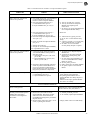
SECTION 1
IDENTIFICATION
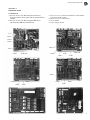
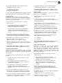
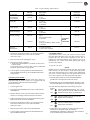
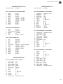
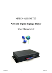
Circuit Boards
A Revision Level 6 CPU Board Required for Memory
Protection Feature and for games that use game ROM and
PROMs.
B Revision Level 4 CPU Board Equipped With Three
PROM Sockets and Game ROM Socket.
C Revision Level 4 CPU Board Without Third PROM
and Game ROM Sockets.
D Revision Level 3 CPU Board
E Driver Board
F Power Supply Board
J3 / J4
PROM 1
PROM 2
PROM 3
PROM 3
ROM 1
ROM 2
GAME ROM
G A M E ROM
ROM 1
PROM 2
PROM 1
ROM 2
PROM 2
PROM 2
ROM 2
PROM 1
ROM 1
ROM 2
PROM 1
ROM 1
2
http://www.firepowerpinball.com
497
SECTION 1
IDENTIFICATION
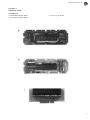
Circuit Boards
G D8000 Master Display Board.
H D8169 Master Display Board.
I Slave Display Board.
3
http://www.firepowerpinball.com
497
SECTION 1
IDENTIFICATION
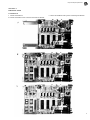
Circuit Boards
J D8224 Sound Board.
K D8224 Sound Board with optional C8228 Speech Module.
L D8224 Sound Board with optional C8226 Speech Module.
4
http://www.firepowerpinball.com
497
SECTION 1
IDENTIFICATION
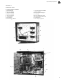
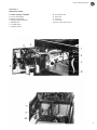
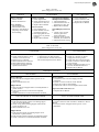
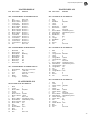
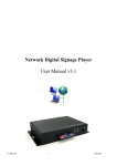
Location of Major Assemblies
A Master Display
B Player 1 Display.
C Player 2 Display.
D Player 3 Display.
E Player 4 Display.
F Driver Board.
G CPU Board
H Power Supply Board.
I Optional Speech Module
J Sound Board
K Keylock for Backglass
L Fuse Card
M Lamp Bridge Rectifier
N Solenoid Bridge Rectifier
O Transformer
P 6C1 Lamp Capacitor
C
B
D
E
A
G
H
I
J
K
L
M
F
N
O
P
5
http://www.firepowerpinball.com
497
SECTION 1
IDENTIFICATION
Location of Major Assemblies
Q Coin Lockout Relay.
R Diagnostic Switches
S Memory Protect Interlock
T Ball Roll Tilt
U Credit Knocker
V Volume Control
W Plumb Bob Tilt
X Slam Tilt
Y Speaker
Z Line Fuse
AA Line Filter and Varistor
6
http://www.firepowerpinball.com
497
SECTION 2
MECHANICAL MAINTENANCE
3. With the playfield up, adjust the short blade for 1/ 16
inch contact gap.
General Switch Blade Adjustments
4. The backup blade (which prevents vibration) should be
adjusted parallel to and just barely in contact with the
blade.
There are different types of switch blades used in any
game. Various lengths, thickness and forms are selected
characteristics to satisfy specific operational conditions
(bounce, current capacity, etc.). For this reason, always use
a blade of the same type for replacement. Basic guidelines
for switch adjustments follow:
Tilt Switches
1. To make the plumb bob tilt more sensitive, raise the
plumb bob on the shaft. To make it less sensitive, lower
the bob on the shaft.
1. Never kink or bend a blade sharply; adjust with a
sweeping, bowing motion with a switch adjusting tool or
duckbill pliers.
2. To make the ball roll tilt more sensitive, raise the
assembly at the front pivot slot. To make it less sensitive,
lower the assembly at the front pivot slot.
2. Before adjusting any switch, check that the screw
holding the switch stack is tight. This is recommended
because spacers in the switch stack occasionally shrink
causing a poor adjustment.
3. The slam tilt and playfield tilt switches are adjusted by
forming the switch blades.
3. Except when otherwise indicated, blade type switches
should have at least 1/32 inch between open contacts
and have at least a 1/ 32 inch follow-thru when closed.
4. First adjust the actuating blade for approximate gapping
and the other blade for the final gap and for follow-thru.
Contact Care
1. Switch contacts should be cleaned only when they cause
a malfunction.
2. For flipper button and flipper end-of-stroke switches,
remove tarnish with a contact file and then burnish.
Severely burnt contacts should be replaced as an assembly.
Flippers
Flippers are controlled by the flipper pushbuttons at each
side of the cabinet. Each coil consists of two windings: a
pullin winding and a lighter gauge hold?in winding. The
hold-in winding is normally bypassed by a closed switch.
The pull-in winding produces a strong stroke. However, if
this winding were to remain energized by the player it
would overheat. To reduce this high current, the hold-in
winding is put in series with the pull-in winding by opening
the end-of-stroke switch.
1. Adjust the long blade so that it is moved by the flipper
pawl assembly for about the last l/ 8 inch of movement.
2. Manually depress the plunger fully and adjust for
approximately 3/32 inch gap.
3. All other types of contacts MUST NOT be filed or
burnished.
3. There should be about 1/32 inch follow-thru with the
plunger released.
4. To clean contacts of other blade type switches, close the
contacts on a clean piece of paper about the thickness of
a business card and wipe gently until the contacts are clean.
4. NEVER LUBRICATE the plunger.
5. For drop target switches, remove the two screws
securing the circuit board. Clean the circuit board
plating with a rag and pencil eraser. Carefully clean the
wiper contacts with a burnishing tool - do not use an
abrasive.
Rollover Switches
Rollover Switches are activated by a wire form or button
which is actuated by the ball.
1. Before adjustment, make sure that the wire form
rollover is centered in the slot or that the switch blades
are positioned under the button actuator.
2. Adjust the long blade (closest to the playfield) to hold
the rollover up. Check this condition with the playfield
lowered.
5. For weak or sluggish flipper action, cheek for all the
following:
a. Dirty, pitted, or misadjusted flipper button or end of
stroke contacts.
b. Worn out coil sleeves.
c. Loose or broken bushing.
d. Worn out fiber links.
e. Weak or broken return spring.
f. Broken flipper shaft.
g. Coil loose
h. Loose screws
i. Flipper binding on playfield.
7
http://www.firepowerpinball.com
497
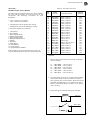
SECTION 3
GAME ADJUSTMENTS
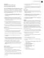
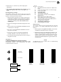
This section provides information for making game
adjustments and reviewing game status. Williams now
provides a greatly simplified method of customizing the game
to the location or the operator's requirements. This section
provides detailed procedures for making these changes.
There are four switches, all accessible from the coin door
(Figure 1) or the front of the cabinet, which are used to
display and change game features:
1. AUTO-UP/MANUAL-DOWN toggle switch (inside
coin door)
2. ADVANCE pushbutton (Inside coin door)
3. High Score Reset switch (Inside coin door)
4. Credit Button - front of cabinet
General Procedure
Game status functions are displayed and can be set in test 04.
To enter test 04, the AUTO-UP/ MANUAL?DOWN switch
is set to AUTO-UP and the ADVANCE pushbutton is
depressed in the game over mode. Test 04 will be entered
with the number of credits display showing 04 and the ball in
play display showing 00.
If problems are encountered making game adjustments (for
example, the ADVANCE pushbutton does not function after
entering test 04) refer to troubleshooting in Section 6.
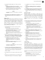
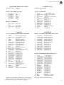
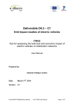
Refer to Table 1. Functions 00 through 12 are system audit
totals and cannot be changed from the coin door. Functions
13 through 35 can all be adjusted from the coin door.
In test 04, to advance from the system audit totals to game
feature status display, the AUTO-UP/MANUAL-DOWN
switch is first set to AUTO-UP. Each time the ADVANCE
pushbutton is depressed, the display will advance to the next
higher function number. Holding the ADVANCE pushbutton
depressed causes the function numbers to advance rapidly.
With the AUTO-UP/ MANUAL-DOWN switch set to
MANUAL-DOWN, depressing (or holding down) the
ADVANCE pushbutton causes the function numbers to
decrease (from 00 to 35 to 34, etc.).
With the desired function number showing in the ball
in play display, the current setting is shown on the
Player 1 display. With the
AUTO-UP/MANUAL-DOWN switch in the AUTO-UP
position, depressing the Credit Button advances the
value of the current setting on the Player 1 display.
Holding the credit button depressed causes the value to
advance rapidly. With the
AUTO-UP/MANUAL-DOWN switch set to
MANUAL-DOWN, depressing (or holding in) the
credit button causes the value to decrease. The value
left showing on the display is the new current
setting.
After all changes have been made and reviewed using
test 04, the game is turned OFF and then back ON to
return to the game over mode.
High Score to Date
Depressing the High Score Reset switch in the game
over mode changes the current high score to date
(Function 12) to the value of the backup high score to
date (Function 13).
The value of function 13 can be changed to any multiple
of 10,000 points. With the value of function 13 set to zero,
the high score to date feature is disabled. To change the
backup high score to date, proceed as follows:
1. If not already in test 04, enter test 04 in one of the
following ways:
a. From the game over mode, set the AUTOUP/MANUAL-DOWN switch to AUTO?UP and
depress the ADVANCE pushbutton.
b. From diagnostics, set the AUTO-UP/MANUALDOWN switch to AUTO-UP and depress the
ADVANCE pushbutton to advance the diagnostics
to test 04. 1
2. Set the AUTO-UP/MANUAL-DOWN switch to the
desired position and operate the advance pushbutton
until function 13 is indicated on the ball in play
display: The backup high score to date is indicated in
the Player 1 display.
Figure 1. Door Diagnostic Switches
8
Game Identification
Coins, Left Chute
(Closest to 2 coin door hinge)
Coins, Center Chute
Coins, Right Chute
Total Paid Credits
Total Specials
Total Replay (Extra Ball) Scores
Match and High Score to Date Credits
Total Credits
Total Extra Balls
Total Ball Time in Minutes
Total Number of Balls Played
Current High Score to Date
Backup High Score to Date
Replay 1 Score
Replay 2 Score
Replay 3 Score
Replay 4 Score
Maximum Credits
Standard and Custom Pricing Control
(00-07)
Left Coin Slot Multiplier
Center Coin Slot Multiplier
Right Coin Slot Multiplier
Coin Units Required for Credit
Coin Units Bonus Point
High Score Credits
Match (00 ON, 01 OFF)
Special
00 = Awards Credit
01 = Awards Extra Ball
02 = Awards Points
Scoring Awards
00 = Credits at R eplay Score
01 = Extra Ball at Replay Score
Maximum Plumb Bob Tilts (1-9)
Number of Balls (03 or 05)
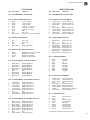
DESCRIPTION
29
30
31
thru
Unique Game Adjustments
35
*Indicates settings are game-dependent.
28
20
21
22
23
24
25
26
27
02
03
04
05
06
07
08
09
10
11
12
13
14
15
16
17
18
19
00
01
FUNCTION
03
03
*
—
00
*
*
*
*
*
03
00
00
—
—
—
—
—
—
—
—
—
—
*
*
*
*
*
0
20
*
1 ggg n
—
FACTORY
SETTINGS
—
—
—
9
9
9
9
9
6
—
—
2
2
2
2
2
2
2.3
2,4
2
2
5
6
7
7
7
7
8
9
1
2
NOTES
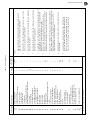
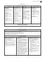
Table 1. Game Adjustments
Functions 01-11 cannot be changed from the coin door; however they
can be set to zero as described in Section 4.
Total Credits (Function 08) is the sum of Function 04 and as applicable,
Functions 05, 06, and 07.
Total Extra Balls (Function 09) is the sum of the game extra ball feature
and Functions 05 and 06, as applicable.
Current High Score to Date (Function 12) can be changed to the value of
the Backup High Score to Date (Function 13) by operating the HIGH
SCORE RESET switch while in the game over mode.
Function 13 may be set to any multiple of 10,000 points. Setting
Function 25 to zero with Function 13 set to any score but zero permits
the High Score to Date feature to operate but no credits are awarded.
Functions 14-17 (Replay Scores) may be set to any multiple of 10,000
points. Setting a function to zero disables the replay score point. Always
disable the Replay 4 level first, the Replay 3 level second, etc. The
replay levels must he set with ascending values.
Setting Maximum Credits (Function 18) to zero places the game in a
free play mode.
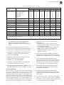
A typical factory setting for pricing is shown. With Function
19 set to 00, Functions 20-24 must be set manually. Refer to
Table 2 or 3 for seven standard pricing schemes (selected by
values of 01-07 for Function 19) and custom pricing values.
2.
3.
4.
5.
7.
8.
9.
6.
Game Identification in Function 00 readout indicates game number
(ggg) and revision level (n) of PROMs or Game ROM.
1.
Notes:
http://www.firepowerpinball.com
497
9
http://www.firepowerpinball.com
497
3. To change the backup high score to date, proceed as
follows:
a. To lower the backup value set the AUTOUP/MANUAL-DOWN switch to MANUAL-DOWN.
To raise the backup value, set it to AUTO-UP.
b. Operate the credit button until the desired backup
value is indicated on the player 1 display.
NOTE
To disable the high score to date feature, set function
13 to zero.
4. If no further game adjustments are required, turn the
game OFF and back ON to return to the game over
mode.
Replay Scores
There are four possible replays awarded from scoring. The
factory setting for the first three replay scores are provided
in Table 1 and on the instruction booklet inside the game.
The fourth replay is disabled. Replay 1 is function 14,
replay 2 function 15, replay 3 function 16, and replay 4
function 17. Replay points can be increased or decreased
by any multiple of 10,000 points. To make changes to
replay points, proceed as follows:
1. If not already in test 04, enter test 04 in one of the
following ways:
a. From the game over mode, set the AUTOUP/MANUAL-DOWN switch to AUTO-UP and
depress the ADVANCE pushbutton.
b. From diagnostics, set the AUTO-UP/MANUALDOWN switch to AUTO-UP and depress the
ADVANCE pushbutton to advance the diagnostics to
test 04.
2. Set the AUTO-UP/MANUAL-DOWN switch to the
desired position and operate the ADVANCE pushbutton
until function 14 is indicated on the ball in play display.
3. To change the score for Replay 1, proceed as follows:
a. To raise the replay points, set the AUTOUP/MANUAL-DOWN switch to AUTO?UP.
To lower the replay points, set it to MANUALDOWN.
b. Operate the Credit button until the desired value is
indicated on the Player 1 display.
NOTE
To disable any replay point, raise or lower the value
in the Player 1 display to zero.
4 With the AUTO-UP/MANUAL-DOWN switch set to
AUTO-UP, depress the ADVANCE pushbutton one
time. Function 15 is indicated on the ball in play display
and the current value of replay 2 is indicated on the
Player 1 display.
5. To change the score for replay 2, perform steps 3a and
3b.
6. Repeat step 4 to display Function 16 on the ball in play
display and the replay 3 score in the Player 1 display.
7. To change the score for replay 3, perform steps 3a
and 3b.
8. Repeat step 4 to display Function 17 on the ball in
play display and the replay 4 score on the Player 1
display.
9. To change the replay 4 score, perform steps 3a and 3b.
10. If no further game adjustments are required, turn
the game OFF and back ON to return to the game over
mode.
Maximum Credits
Maximum credits is the number of credits that can be
posted (by putting coins in the game or free credit awards)
before the coin lockout relay is released. Maximum credits
is Function 18 and the factory setting is 20. Maximum
credits may be set to any value from 1 to 99; setting
maximum credits to zero sets the game to a free play
mode.
To make changes to maximum credits, proceed as follows:
1. If not already in test 04, enter test 04 in one of the
following ways:
a. From the game over mode, set the AUTOUP/MANUAL-DOWN switch to AUTO?UP and
depress the ADVANCE pushbutton.
b. From diagnostics, set the AUTO-UP/MANUALDOWN switch to AUTO-UP and depress the
ADVANCE pushbutton to advance the diagnostics to
test 04.
2. Set the AUTO-UP/MANUAL-DOWN switch to the
desired position and operate the ADVANCE
pushbutton until Function 18 is indicated on the ball in
play display.
3. To raise the maximum credits set the AUTOUP/MANUAL-DOWN switch to AUTO-UP.
To lower the maximum credits set it to MANUALDOWN.
4. Operate the Credit button until the desired number of
maximum credits is indicated on the Player 1
display.
5. If no further game adjustments are required, turn the
game OFF and back ON to return to the game over
mode.
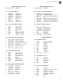
Game Pricing
Standard. Game Pricing
This feature accounts for differences in coin door
mechanisms and how credits are awarded. Function 19 can
be set to select one of seven standard game pricing schemes
with fixed values for Functions 20 through 24. (Function
19 can also be set to allow custom pricing schemes where
Functions 20 through 24 are set with appropriate values as
described in the CUSTOM GAME PRICING paragraphs).
To select one of the standard pricing schemes, proceed as
follows:
1. If not already in test 04, enter test 04 in one of the
following ways:
a. From the game over mode, set the AUTOUP/MANUAL-DOWN switch to AUTO-UP and
depress the ADVANCE pushbutton.
10
http://www.firepowerpinball.com
497
Table 2. Standard and Custom Price Settings
COIN DOOR
FUNCTION
MECHANISM
CREDITS
19
20
21
22
23
24
Twin-Quarter
Quarter, Dollar, Quarter
1 / 25¢, 3 / 50¢, 7 / $1
1 / 25¢, 3 / 50¢, 7 / $1 coin only
1 / 25¢, 7 / $1 coin only
1 / 25¢, 3 / 50¢, 6 / $1
1 / 25¢, 6 / $1 coin only
• 1 / 25¢, 5 / $1
1 / 25¢, 5 / $1 coin only
• 1 / 25¢, 4 / $1
• 1 / 25¢, 3 / $1
1 / 50¢
00
00
00
00
00
05
00
02
01
00
03
03
01
01
01
01
01
01
01
01
12
14
07
04
06
04
05
04
04
04
03
03
01
01
01
01
01
01
01
01
02
02
01
01
01
01
01
01
02
02
12
00
00
02
00
04
00
00
04
00
1DM, 5DM, 2DM
• 1 / 1DM, 3 / 2DM, 10 / 5DM
2 / 1DM, 5 / 2DM, 14 / 5DM
03
00
09
13
45
65
18
26
05
05
45
65
20-Cent, 50-Cent
1 / 20¢, 3 / 50¢
00
06
00
15
05
00
1 Franc, 10 Franc, 5 Franc
• 1 / 2F, 3 / 5F only, 8 / 10F only
04
01
16
06
02
00
25 Cent,
1 Guilder
• 1 / 25¢, 4 / 1G
1 / 25¢, 5 / 1G
06
00
01
01
00
00
04
04
01
01
00
04
50 Yen, 100 Yen
• 1 / 50Y, 2 / 100Y
07
01
00
02
01
00
1 Franc or
Twin-1 Franc
1 / 1F, 3 / 2F
1 / 1F
00
00
01
01
01
01
01
01
01
01
02
00
5 Franc,
10 Franc
• 1 / 5F, 2 / 10F
1 / 10F
07
00
01
01
00
00
02
02
01
02
01
00
Twin-2 Franc
• 1 / 2F
02
01
04
01
01
00
10, 20 Franc
• 1 / 10F, 2 / 20F
07
01
00
02
01
00
Twin-1 Sucre
1 / 3S, 2 / 5S
00
02
00
02
05
00
• Indicates standard price settings by adjusting only Function 19. For other price settings, set Function 19 to 00 and set Functions 20
through 24 to the values indicated in the chart.
b. From diagnostics, set the AUTO-UP/MANUALDOWN switch to AUTO-UP and depress the
ADVANCE pushbutton to advance the diagnostics to
test 04.
2. Set the AUTO-UP/MANUAL-DOWN switch to the
desired position and operate the ADVANCE pushbutton
until Function 19 is indicated on the ball in play display.
3. Refer to Table 2 and determine the value of Function 19
required for the desired pricing scheme. (Standard
pricing is set in bold type).
4. To raise the value of Function 19 set the AUTO-UP/
MANUAL-DOWN switch to AUTO-UP.
To lower, set it to MANUAL-DOWN.
5. Operate the Credit button until the value determined in
step 3 is shown in the Player 1 display.
6. If no further game adjustments are required, turn the
game OFF and back ON to return to the game over mode.
Custom Game Pricing
With Function 19 set to zero, the live Functions 20 through
24 may be set manually for custom game pricing
requirements. Functions 20, 21, and 22 relate to the type of
coin door mechanism and Functions 23 and 24 relate to how
credits are awarded. A large number of custom game pricing
schemes are provided in Table 2 and are set in light type. If
the required pricing scheme is not provided in Table 2, refer
to the explanation that follows the procedure to determine the
values for Functions 20 through 24. Proceed as follows:
1. If not already in test 04, enter test 04 in one of the
following ways:
a. From the game over mode, set the AUTO-UP/
MANUAL-DOWN switch to AUTO-UP and depress
the ADVANCE pushbutton.
b. From diagnostics, set the AUTO-UP/ MANUALDOWN switch to AUTO-UP and depress the
ADVANCE pushbutton to advance the
diagnostics to test 04.
2. Set the AUTO-UP/MANUAL-DOWN switch to the
desired position and operate the ADVANCE push button
until Function 19 is indicated on the no. of credits display.
3. Set the AUTO-UP/MANUAL-DOWN switch to
MANUAL-DOWN and operate the Credit button until
00 is indicated for Function 19 on the Player 1 display.
With Function 19 set to 00, Functions 20 through 24
are set to zero and now can be changed as required.
4. Refer to Table 2 (or use the explanation following
this procedure) and determine the required values
for Functions 20 through 24.
5. Set the AUTO-UP/MANUAL-DOWN switch to
AUTO-UP and momentarily depress the ADVANCE
pushbutton. Function 20 should be indicated on the ball
in play display.
6. For single chute coin doors, omit this step and leave the
value of 00. For twin or 3?chute coin doors, operate the
Credit button until the value for Function 20 determined
11
in step 4 is indicated in the Player 1 display.
http://www.firepowerpinball.com
497
7. Momentarily depress the ADVANCE pushbutton.
Function 21 should be indicated on the ball in play
display.
8. For twin chute coin doors, omit this step and leave the
value of 00. For single and 3 chute coin doors, operate
the Credit button until the value for Function 21
determined in step 4 is indicated on the Player 1 display.
9. Momentarily depress the ADVANCE pushbutton.
Function 22 should be indicated on the ball in play
display.
10. For single chute coin doors omit this step and leave the
value of 00. For twin or 3?chute coin doors, operate the
Credit button until the value for Function 22
determined in step 4 is indicated on the Player 1 display.
11. Momentarily depress the ADVANCE pushbutton.
Function 23 should be indicated on the ball in play
display.
12. Operate the credit button until the value for Function 23
determined in step 4 is indicated in the Player 1 display.
13. Momentarily depress the ADVANCE pushbutton.
Function 24 should be indicated on the ball in play
display.
14. Omit this step if no bonus credits are to be awarded for
inserting a certain value of coins. To award bonus
credits, operate the Credit button until the value for
Function 24 determined in step 4 is indicated on the
Player 1 display.
15. If no other game adjustments are to be made, turn
the game OFF and back ON to return to the game over mode.
Pricing Formulas
There are five different functions used to set custom game
pricing. Three pertain to the coin door mechanism and the
other two determine how credits are awarded. Since there
are many combinations of coin values and coin
mechanisms, this explanation details how the functions
relate to each other and provides a generalized procedure
for defining the desired pricing scheme.
Proportional values are assigned to Functions 20, 2 1, and
22 for the left (closest to hinge on coin door), center, and
right coin chute, respectively.
Function 23 defines the value of coins required for a single
credit in relation to the proportional values assigned to
functions 20, 21, and 22. Function 24 permits awarding a
bonus credit for depositing some value of coin(s). A general
procedure follows:
1. Determine the ratio of the coin chute values by dividing
by the largest number that leaves a remainder of zero.
Examples:
25c 25c 25c; ÷ 25 1: 1: 1
1DM 5DM 2DM 1 = 1:5:2
25c - 1G ÷ 4 = 1:0:4
5c 10c 25c ÷ 5 = 1:2:5
2. Determining the values of Functions 20 through 24 is
done in one of two ways. The first method requires that
bonus credit Function 24 be set to zero. The second
method defines the Function 24 value. Since some
pricing schemes may be implemented with either
method, some with only the first method, and others
with only the second method, both methods will have to
be tried in some cases.
Both methods use the ratio calculated in step 1, the largest
number of credits defined in the pricing scheme, and the
number of smallest value coins required to obtain the
largest number of credits.
Method 1
Function 20 = Cd x L
Function 21 = Cd x C
Function 22 = Cd x R
Function 23 = Cn x Lr
Function 24 = 00
Method 2
Function 20 = (Cd - 1) x L
Function 21 = (Cd - 1) x C
Function 22 = (Cd - 1) x R
Function 23 = Cn x Lr
Function 24 = Cn x (Cd - 1)
Where:
Cd = the largest number of credits in scheme
Cn = the number of smallest value coins required for Cd
L = Left chute ratio number
C = Center chute ratio number
R = Right chute ratio number
Lr = Lowest coin chute ratio
Examples:
25c - 25c Coin door
1 Play/25c, 3 Plays/50c
Ratio= 1:0:1
L = 1
C = 0
R = 1
Lr = 1
In this example either method will produce proper values
for functions 20-24.
Method 1
Cd = 3
Cn = 2 (two 25c coins for 3 plays)
Function 20 = Cd x L = 3 x 1 = 03
Function 21 = Cd x C = 3 x 0 = 00
Function 22 = Cd x R = 3 x 1 = 03
Function 23 = Cn x Lr = 2 x 1 = 02
Function 24 = 00
Method 2
Cd = 3
Cn = 2
Function 20 = (Cd - 1) x L = (3-1) x 1 = 02
Function 21 = (Cd - 1) x C = 00
Function 22 = (Cd - 1) x R = 02
Function 23 = Cn x Lr = 2 x 1 = 02
Function 24 = Cn x (Cd - 1) = 2 x (3-1) = 2 X 2 = 04
5c 10c 25c Coin door
1 Play/15c, 2 Plays/25c
Ratio = 1:2:5
L =1
C =2
R =5
Lr = 1
In this example, method 1 provides proper values but
method 2 will not:
Method 1
Cd = 2
Cn = 5 (five 5c coins required for 2 plays)
12
http://www.firepowerpinball.com
497
Function 20 = Cd x L = 2 x 1 = 02
Function 21 = Cd x C = 2 x 2 = 04
Function 22 = Cd x R = 2 x 5 = 10
Function 23 = Cn x Lr = 5 x 1 = 05
Function 24 = 00
Method 2
Cd = 2
Cn = 5
Function 20 = (Cd-1) x L = (2-1) x 1 = 01
Function 21 = (Cd-1) x C = (2-1) x 2 = 02
Function 22 = (Cd-1) x R = (2-1) x 5 = 05
Function 23 = Cn x Lr = 5 x 1 = 05
Function 24 = Cn x (Cd?1) = 5 X (2?1) = 05
By studying the values obtained in method 2 it will be
determined that the values set up pricing for 2 plays for 25c
(no plays for 15c). This example shows that some pricing
schemes can be set up using only one of the methods.
20c - 50c Coin door
1 Play/20c, 3 Plays/50c
Ratio = 2:0:5
L2
C0
R5
Lr 2
In this example, only method 1 will produce proper values.
Method 1
Cd = 3
Cn = 2.5 (two and one-half 20c coin required for 3 plays)
Function 20 = Cd X L = 3 X 2 = 06
Function 21 = Cd X C = 3 X 0 = 00
Function 22 = Cd X R = 3 X 5 = 15
Function 23 = Cn X Lr = 2.5 X 2 = 05
Function 24 = 00
High Score Credits
Function 25 determines the number of credits to be awarded
when the current highest score is exceeded by a player. Note
that the backup high score to date (Function 13) must be set
to some value other than zero for the high score feature to
operate. With Function 25 set to zero and Function 13 set to
any value other than zero, the high score to date feature will
still function but no credits will be awarded. To change the
number of credits for exceeding the high score, proceed as
follows:
1. If not already in test 04, enter test 04 in one of the
following ways:
4. Operate the credit button until the desired number of
high score credits is indicated on the player 1 display.
5. If no further game adjustments are required, turn the
game OFF and back ON to return to the game over
mode.
Match
Function 26 controls the match features. If this function is
set to 00, the match feature is on. If it is set to 01 , the
feature is off. With the match feature on, a free credit is
awarded at game over when the last two digits of a players
score match the digits shown in the ball in play display.
To change the match feature, proceed as follows:
1. If not already in test 04, enter test 04 in one of the
following ways:
a. From the game over mode, set the AUTOUP/MANUAL-DOWN switch to AUTO-UP and
depress the ADVANCE pushbutton.
b. From diagnostics, set the AUTO-UP/MANUALDOWN switch to AUTO-UP and depress the
ADVANCE pushbutton to advance the diagnostics to
test 04.
2. Set the AUTO?-UP/MANUAL-DOWN switch to the
desired position and operate the ADVANCE
pushbutton until Function 26 is indicated on the ball in
play display.
3. To raise the value of Function 26, set the AUTOUP/MANUAL-DOWN switch to AUTO?UP.
To lower the value, set it to MANUAL?DOWN.
4. Operate the credit button until the desired value is
indicated on the player 1 display (00 for match on or 01
for match off).
5. If no further adjustments are required, turn the
game OFF and back ON to return to the game over mode.
Special
Function 27 controls the special feature. If this function is
set to 00, a special awards a free credit; with the feature set
to 01 or 02, a special awards an extra ball or bonus points,
respectively. To change the award for a special, proceed as
follows:
1. If not already in test 04, enter test 04 in one of the
following ways:
a. From the game over mode, set the
AUTO-UP/MANUAL-DOWN switch to AUTO-UP
and depress the ADVANCE pushbutton.
a. From the game over mode, set the AUTOUP/MANUAL-DOWN switch to AUTO-UP and
depress the ADVANCE pushbutton.
b. From diagnostics, set the AUTO-UP/MANUALDOWN switch to AUTO-UP and depress the
ADVANCE pushbutton to advance the diagnostics to
test 04.
b. From diagnostics, set the AUTO-UP/MANUALDOWN switch to AUTO-UP and depress the
ADVANCE pushbutton to advance the diagnostics to
test 04.
2. Set the AUTO?UP/ MANUAL?DOWN switch to the
desired position and operate the ADVANCE pushbutton
until Function 25 is indicated on the ball in play display.
2. Set the AUTO-UP/MANUAL-DOWN switch to the
desired position and operate the ADVANCE
pushbutton until Function 27 is indicated on the ball in
play display.
3. To increase the number of credits, set the AUTOUP/MANUAL-DOWN switch to AUTO?UP.
To decrease the number of credits, set it to MANUALDOWN.
3. To raise the value of Function 27, set the AUTOUP/MANUAL-DOWN switch to AUTO-UP.
To lower the value, set it to MANUAL-DOWN.
13
http://www.firepowerpinball.com
497
4. Operate the Credit button until the desired value is
indicated in the player 1 display:
00 - Special Awards Credit
01 Special Awards Extra Ball
02 Special Awards Points
5. If no other game adjustments are required, turn the
game OFF and back ON to return to the game over mode.
Scoring Awards
Function 28 controls whether exceeding replay points
awards a free credit or an extra ball. Setting the function to
00 awards a credit; setting it to 01 awards an extra ball. To
adjust scoring, proceed as follows:
1. If not already in test 04, enter test 04 in one of the
following ways:
a. From the game over mode, set the AUTO-UP/
MANUALDOWN switch to AUTO-UP
and depress the ADVANCE pushbutton.
b. From diagnostics, set the AUTO-UP/MANUALDOWN switch to AUTO-UP and depress the
ADVANCE pushbutton to advance the diagnostics to
test 04.
2. Set the AUTO-UP/MANUAL-DOWN switch to the
desired position and operate the ADVANCE pushbutton
until Function 28 is indicated on the ball in play display.
3. To raise the value of Function 28, set the AUTO-UP/
MANUAL-DOWN switch to AUTO-UP.
To lower the value, set it to MANUAL-DOWN.
4. Momentarily depress the Credit button so that the desired
value is indicated on the player 1 display (00 for credit, 01
for extra ball).
5. If no further adjustments are required, turn the game
OFF and back ON to return to the game over mode.
Maximum Plumb Bob Tilts
Function 29 controls the multiple tilt feature. The plumb
bob tilt can be set so that the ball in play does not tilt the
first time that the bob contacts the ring. All tilts do not have
this capability.
To change the number of plumb bob tilts (1-9) proceed as
follows:
1. If not already in test 04, enter test 04 in one of the
following ways:
a. From the game over mode, set the AUTO-UP/
MANUALDOWN switch to AUTO-UP and depress
the ADVANCE pushbutton.
b. From diagnostics, set the AUTO-UP/MANUALDOWN switch to AUTO-UP and depress the
ADVANCE pushbutton to advance the diagnostics to
test 04.
2. Set the AUTO-UP/MANUAL-DOWN switch to the
desired position and operate the ADVANCE pushbutton
until Function 29 is indicated on the ball in play display.
3 To increase the number of plumb bob tilts, set the AUTOUP/MANUAL-DOWN switch to AUTO-UP. To decrease
the number, set it to MANUAL-DOWN.
4. Operate the credit button until the desired number of
plumb bob tilts is indicated on the player 1 display.
5. If no further game adjustments are required, turn the
game OFF and back ON to return to the game over mode.
Number of Balls
Function 30 controls the number of regular balls. To adjust
Function 30 proceed as follows:
1. If not already in test 04, enter test 04 in one of the
following ways:
a. From the game over mode, set the AUTO-UP/
MANUAL-DOWN switch to AUTO-UP and depress the
ADVANCEpushbutton.
b. From diagnostics, set the AUTO-UP/MANUALDOWN switch to AUTO-UP and depress the ADVANCE
pushbutton to advance the diagnostics to test 04.
2. Set the AUTO-UP/MANUAL-DOWN switch to the
desired position and operate the ADVANCE pushbutton
until Function 30 is indicated on the ball in play display.
3. To increase the number of regular balls per game, set the
AUTO-UP/MANUAL-DOWN switch to AUTO-UP.
To decrease the number, set it to MANUAL-DOWN.
4. Operate the credit button until the desired number of
balls is indicated in the player 1 display.
03 - 3 Ball Play
05 - 5 Ball Play
5. If no further game adjustments are required, turn the
game OFF and back ON to return to the game over
mode.
Unique Game Adjustments
Functions 31 through 35 provide game-dependent
adjustments for the Extra Ball feature, liberal to
conservative play, playfield restore, and (when applicable)
sound options. For adjustment values, refer to the
supplemental manual or to the game adjustment and
diagnostic procedures booklet provided with the specific
game. Proceed as follows:
1. If not already in test 04, enter test 04 in one of the
following ways:
a. From the game over mode, set the AUTO
UP/MANUAL-DOWN switch to AUTO-UP and
depress the ADVANCE pushbutton.
b. From diagnostics, set the AUTO-UP/MANUAL
DOWN switch to AUTO-UP and depress the
ADVANCE pushbutton to advance the diagnostics
to test 04.
2. Set the AUTO-UP/MANUAL-DOWN switch to the
desired position and operate the ADVANCE push
button until the function number is indicated on the ball
in play display.
3. To raise the value, set the AUTO-UP/MANUAL-DOWN
switch to AUTO-UP.
To lower the value set it to MANUAL-DOWN.
4. Operate the credit button until the desired value is
indicated on the player 1 display.
14
http://www.firepowerpinball.com
497
5. Repeat steps 2, 3, and 4 for any other unique game
adjustments.
TEST 04
READOUT DESCRIPTION
6. If no further game adjustments are required, turn the
game OFF and back ON to return to the game over
mode.
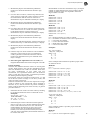
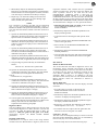
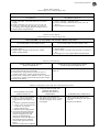
Restoring Factory Settings
The factory settings are restored using the coin door
switches and two switches on the CPU Board. Refer to
Figures 1 and 2 and proceed as follows:
1. With the game in the game over mode, set the AUTOUP/MANUAL-DOWN switch to MANUAL-DOWN
and momentarily depress the ADVANCE pushbutton.
All displays should go blank. The coin door must
remain open.
2. Remove the backglass and unlatch and open the insert
door.
00
01
02
03
04
05
06
07
08
09
10
11
12
PROM Identification (Game No. and Revision
level)
Coins Left Chute (Closest to coin door hinge)
Coins Center Chute
Coins Right Chute
Total Paid Credits
Total Number of Specials
Total Number of Credits or Extra Balls for
Replay Scores
Match/ High Score to Date Credits
Total Credits (Sum of 04-07 as applicable)
Total Extra Balls (Sum of Extra Ball features,
and 05 and 06 as applicable)
Total Ball Time in Minutes
Total Number of Balls played
Current High Score to Date
3. Set all switches on the MASTER COMMAND switch
to OFF (move to the right).
Feature Access
All of these features can be accessed from the coin door
(See Figure 1). To obtain bookkeeping totals proceed as
follows:
4. Set switch 7 on the MASTER COMMAND switch to
ON (move to the left).
1. With the game in the game over mode, set the AUTOUP/MANUAL-DOWN switch to AUTO-UP.
5. Momentarily depress the MASTER COMMAND
ENTER pushbutton. The LEDs should blink once.
2. Momentarily depress the ADVANCE pushbutton. The
game will go immediately to diagnostics test 04. The
number of credits display indicates 04; the ball in play
display indicates function 00, and the Player 1 display
indicates the PROM identification (game number and
revision level).
RESTORE
FA C T O R Y
SETTINGS
1 2 3 4 5 6 7 8
O
N
1 2 3 4 5 6 7 8
1 2 3 4 5 6 7 8
O
N
1 2 3 4 5 6 7 8
1 2 3 4 5 6 7 8
O
N
1 2 3 4 5 6 7 8
ZERO
AUDIT
T O TA L S
NOTE
If 'Indications are not as stated, refer to troubleshooting
procedures in Section 6.
O
N
O
N
MASTER
COMMAND
ENTER
NOT USED
O
N
1 2 3 4 5 6 7 8
LED
MASTER
COMMAND
O
N
LED
1 2 3 4 5 6 7 8
SECTION 4
GAME BOOKKEEPING AND EVALUATION
This section provides an explanation of the built-in game
bookkeeping features. The bookkeeping and game
evaluation features consist of..
O
N
6. Turn the game OFF and back ON two times to return to
the game over mode.
AUTO-CYCLE
MODE
DIAGNOSTIC
15
http://www.firepowerpinball.com
497
3. Momentarily depress the ADVANCE pushbutton.
Function 01 is indicated on the number of credits display
and the number of coins through the left chute (closest to
coin door hinge) is indicated on the Player 1 display.
4. Repeat step 3 to obtain the readings for functions 02
(coins through center chute), 03 (coins through right
chute), and 04 (total paid credits).
NOTE
If it is desired to recheck a total that you have advanced
past, set the AUTO-UP/MANUAL-DOWN switch to
MANUAL-DOWN and operate the ADVANCE pushbutton.
This will cause the function number to decrease (from 04 to
03, etc.)
5. Operate the ADVANCE pushbutton until Function 05 is
indicated in the ball in play display. The total number of
Special awards is indicated on the Player 1 display.
6. Operate the ADVANCE pushbutton until Function 06 is
indicated in the ball in play display. The total number of
credits or extra balls for replay scores is indicated in the
Player 1 display.
7. Operate the ADVANCE pushbutton until Function 07 is
indicated on the ball in play display. The total credits
awarded for the Match and High Score to Date features is
indicated on the player 1 display.
8. Operate the ADVANCE pushbutton until Function 08 is
indicated on the ball in play display. The total credits (sum
of paid credits and, as applicable, Functions 06 through 08).
9. The percentage of paid credits may be calculated as
follows:
Function 04 ÷ Function 08 % paid credits
10. Operate the ADVANCE pushbutton until Function 09
is indicated on the ball in play display. The total number
of extra balls (sum of the game extra ball feature,
Special,
and Function 06, as applicable).
11.Operate the ADVANCE pushbutton until Function 10
is indicated on the ball in play display. The total ball time
in minutes is indicated on the player 1 display.
12. Operate the ADVANCE pushbutton until Function 11 is
indicated on the ball in play display. The total number of
balls is indicated on the player 1 display.
13. Operate the ADVANCE pushbutton until Function 12 is
indicated on the ball in play display. The current High
Score to Date is indicated on the player 1 display.
14. Turn the game OFF and back ON to return to the game
over mode. If desired, reset the High Score to Date to the
backup value and reset the audit totals to zero as
explained in the following paragraphs.
High Score Reset
The current High Score to Date (Function 12) may be reset
to the backup High Score to Date (Function 13) from the
coin door. To adjust the backup High Score to Date, see
Section 3. With the game in the game over mode,
momentarily depress the HIGH SCORE RESET
pushbutton.
Resetting Audit Totals
Functions 01 to 11 may be reset to zero using switches
located on the CPU Board. Refer to Figure 2, there are two
8-position miniature slide switches and two pushbutton
switches located on the right side of the CPU Board. The
lower 8-position switch is not used and the lower
(DIAGNOSTIC) pushbutton switch is used only for
troubleshooting. Switch number 8 on the MASTER
COMMAND slide switch is set to ON (moved to the left) and
all other switches are set to OFF (moved to the right). Then
the MASTER COMMAND ENTER pushbutton is depressed.
To reset Function 0 1 through 11 to zero, proceed as follows:
1. With the game in the game over mode, set the coin door
AUTO-UP/MANUAL-DOWN switch to
MANUALDOWN.
2. Momentarily depress the ADVANCE pushbutton. All
displays should go blank.
3. Unlock and remove the backglass and open the insert
door.
4. Move all switches on the MASTER COMMAND slide
switch to the right (OFF).
5. Move switch 8 on the MASTER COMMAND slide
switch to the left (ON).
6. Momentarily depress the MASTER COMMAND
ENTER pushbutton.
7. Close and latch the insert door and replace the backglass.
Turn the game OFF and back ON to return to the game
over mode.
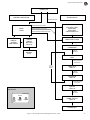
SECTION 5
BUILT-IN DIAGNOSTICS
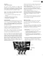
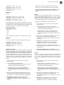
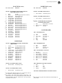
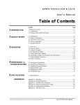
This section describes the built-in diagnostics used to test
the displays, lamps, solenoids, and switches in the game.
Control of diagnostics is from two switches in the coin door.
An Auto-Cycle test, which is initiated by switches on the
CPU Board, repeatedly tests the displays, lamps, and
solenoids. Refer to Figure 3. In addition to the tests
described in this section, there are CPU Board and Sound
Board self-tests which are described in Section 6,
Maintenance.
Display Digits Test
This test allows a complete test of all the displays. Proceed
as follows:
1 From the game over mode, set the AUTO-UP/
MANUAL-DOWN switch on the coin door to
MANUAL-DOWN.
2. Momentarily depress the ADVANCE pushbutton on the
coin door. All displays should go blank.
3. Momentarily depress the ADVANCE pushbutton again.
All displays should indicate all O's.
4. Repeat step 3, as desired. The indication on the displays
should sequence to all 1's, 2's, ... 9's, and 0's ...
5. If no further tests are required, turn the game OFF and
back ON to return to the game over mode.
Lamp Test – Test 01
This test causes all multiplexed lamps to blink on and off.
Note that general illumination lamps are not controlled by
this test or by any test. Proceed as follows:
1. Enter the Lamp Test in one of the following ways:
16
http://www.firepowerpinball.com
497
POWER ON
DIAGNOSTICS
NORMAL OPERATION
BATTERY FAILURE
PRESS DIAGNOSTIC START
GAME
OVER
INSERT
COIN(S)
FOR CREDIT
PRESS ADVANCE IN AUTO-UP
PRESS ADVANCE IN MANUAL-DOWN
CPU SELF TEST
ROM TEST
RAM TEST
CMOS RAM TEST
LEDS BLINK TWICE
PRESS
CREDIT
BUTTON
TO PLAY
ENTER MASTER
COMMANDS
PRESS
ADVANCE
NORMAL
PLAY
DISPLAY DIGITS
TEST
PRESS ADVANCE
IN AUTO-UP
AUTO
CYCLE
MODE
LAMP TEST
TEST 01
PRESS
ADVANCE
SOLENOID
TEST 02
PRESS ADVANCE
IN AUTO-UP
COIN DOOR DIAGNOSTICS
SWITCHES
DIAGNOSTIC
AUTO-UP
HIGH
SCORE
RESET
MANUALDOWN
ADVANCE
SWITCH
TEST 03
PRESS
ADVANCE
DISPLAY/CHANGE
GAME STATUS
TEST 04
POWER OFF
Figure 3. Normal Operation and Diagnostic Flow Chart
17
http://www.firepowerpinball.com
497
a. From the Display Digits test, set the AUTO
UP/MANUAL-DOWN switch to AUTO-UP and
momentarily depress the ADVANCE pushbutton.
b. From the game over mode,
(1) Set the AUTO-UP/ MANUAL-DOWN switch to
MANUAL-DOWN and momentarily depress the
ADVANCE pushbutton.
(2) Set the switch to AUTO-UP and operate the
ADVANCE pushbutton until 01 is indicated on the
number of credits display.
The multiplexed lights should blink on and off.
2. If no further tests are required, turn the game OFF and
back ON to return to the game over mode.
Solenoid Test –Test 02
This test permits checking of all solenoids by causing the
Driver Board to pulse each solenoid. Proceed as follows:
1. Enter the Solenoid Test in one of the following ways:
a. From the Display Digits or Lamp Test, set the
AUTO-UP/MANUAL-DOWN switch to AUTOUP
and operate the ADVANCE pushbutton until 02 is
indicated on the number of credits display.
b. From the game over mode,
(1) Set the AUTO-UP/ MANUAL-DOWN switch to
MANUAL-DOWN and momentarily depress the
ADVANCE pushbutton.
(2) Set the switch to AUTO-UP and operate the
ADVANCE pushbutton until 02 is indicated in the
number of credits display.
The ball in play display should indicate each solenoid
number as it is being pulsed.
2. To repeatedly pulse solenoids one at a time set the switch
to MANUAL-DOWN and momentarily depress the
ADVANCE pushbutton. The solenoid number indicated
in the ball in play display should be pulsed repeatedly.
3. If it is desired to change game adjustment or review game
status, refer to Section 3, Game Adjustments. Otherwise,
turn the game OFF and back ON to return to the game
over mode.
Auto Cycle Mode
This mode is provided to help diagnose intermittent problems
by continuously performing the Display Digits, Lamps, and
Solenoid Tests. Each cycle of this mode sequences through
the display tests, flashes the lamps 64 times, and pulses each
solenoid. This mode is initiated by using the coin door
switches and two switches on the CPU Board. Refer to
Figures 1 and 2 and proceed as follows:
1. With the game in the game over mode, set the AUTOUP/MANUAL-DOWN switch to MANUAL-DOWN and
momentarily depress the ADVANCE pushbutton. All
displays should go blank.
2. Remove the backglass and unlatch and open the insert door.
3. Set all switches on the MASTER COMMAND slide
switch to OFF (move to the right).
4. Set switch 6 to ON (move to the left).
5. Momentarily depress the MASTER COMMAND ENTER
pushbutton. The LED's should blink once.
6. Set the AUTO-UP/MANUAL-DOWN switch to AUTOUP and momentarily depress the ADVANCE pushbutton.
The Auto Cycle mode should start with the display digits
test.
7. To gain manual control during the Display Digits Test,
momentarily depress the ADVANCE pushbutton with the
toggle switch set to MANUAL-DOWN.
8. To return to the Auto Cycle mode, set the toggle switch to
AUTO-UP and momentarily depress the ADVANCE
pushbutton.
3. Each time the ADVANCE pushbutton is depressed, the
next solenoid will be indicated in the ball in play display
and will be pulsed.
9. To gain manual control during the Solenoid test,
momentarily depress the ADVANCE pushbutton with the
toggle switch set to MANUAL-DOWN.
4. If no further tests are required, turn the game OFF and
back ON to return to the game over mode.
10.To return to the Auto Cycle mode, set the toggle switch
to AUTO-UP.
Switch Test –Test 03
This test permits checking of all multiplexed switches in the
game. Proceed as follows:
11.To exit the Auto Cycle mode and advance to Switch Test
03, set the toggle switch to AUTO-UP and depress the
ADVANCE pushbutton during the Solenoid Test.
Operation is now as previously described for Test 03.
1. Enter the Switch Test in one of the following ways:
a. From the Display Digits, Lamp, or Solenoid Tests,
set the AUTO-UP/MANUAL-DOWN switch to
AUTO-UP and operate the ADVANCE pushbutton
until 03 is indicated on the number of credits display.
b. From the game over mode,
(1) Set the AUTO-UP/ MANUAL-DOWN switch to
MANUAL-DOWN and momentarily depress the
ADVANCE pushbutton.
(2) Set the switch to AUTO-UP and operate the
ADVANCE pushbutton until 03 is indicated on the
number of credits display.
All stuck switches will be sequentially indicated on the ball
in play display. If there are no stuck switches. the display
will be blank.
2. Actuate each switch and cheek for the proper switch
number on the ball in play display.
12.To terminate the Auto-Cycle mode and go to game over,
turn the game OFF and back ON.
SECTION 6
MAINTENANCE
This section provides procedures for board replacement, CPU
and Sound Board self-tests, and troubleshooting procedures.
For any problems first perform the CPU Board Self-Tests.
For sound problems also perform the Sound Board Self-Test.
After performing the self-test(s), refer to the troubleshooting
charts that follow.
Board Replacement
CPU Board
To remove the CPU Board, the Driver Board must first be
unmounted. Revision level 6 CPU Boards are required for
the memory protection feature. If a game ROM is used
instead of PROMs, jumper J3 must be connected and J4 18
http://www.firepowerpinball.com
497
removed; if a game ROM and PROMs are used, J4 must be
connected and J3 removed. Refer to the Foreword of the
Game Manual for specific requirements if earlier CPU Boards
must be used. To replace the CPU Board, proceed as follows:
Power Supply Board
Fuse F4 (I 10A SB or, tor games with four flippers, 15A SB)
for flipper solenoids must be installed on the replacement
board. Proceed as follows:
1. Turn the game OFF.
1. Turn the game OFF.
2. Remove the six screws and star washers that secure the
driver board to its mounting bracket.
2. Unplug the six cables from the board.
3. Carefully unplug the Driver Board from the CPU Board.
4. Disconnect the seven plugs from the CPU Board.
5. Remove the two screws and star washers that secure the
top of the CPU Board to its mounting bracket in the
backbox. (The bottom of the board is secured by a
groove in the bracket.)
6. Lift the CPU Board up and remove it from the backbox.
7. Inspect the PROMs and ROMs
a. If the replacement board does not have proper PROMS
or Game ROM, use the ICs from the old CPU board.
b. If the replacement board does not have green-labeled
ROMs, use the ROMs from the old board.
8. For revision level 6 CPU Boards using a Game ROM,
check that jumpers J3/J4 are connected as appropriate.
9. Set the replacement CPU Board into the groove in the
bracket and secure it at the top with the two screws and
star washers removed in step 5.
10. Reconnect the cables disconnected in step 4 using the
keys and cut-off pins as a guide. Make sure that the pins
are aligned, the connectors are firmly seated, and that no
pin terminations have been pushed out of the plugs.
3. Remove the six screws and star washers that secure the
board to its mounting bracket.
4. Position the replacement board on the mounting bracket
and secure with the six screws and star washers removed
in step 2.
5. Reconnect the six cables unplugged in step 2.
6. Turn the game ON and check power supply voltage using
Table 3 as a guide.
Master Display Board
Proceed as follows:
1. Turn the game OFF.
2. Unplug the seven cables from the board.
3. Remove the four nuts and lockwashers that secure the
board to the nylon spacers on the insert door and remove
the board.
4. Position the replacement board on the spacers and secure it
using the four nuts and lockwashers removed in step 3.
5. Reconnect the seven cables unplugged in step 2.
6. Turn the power ON and perform the display digits test in
accordance with procedures provided in Section 5.
Slave Display Board
Proceed as follows:
11. Carefully plug the Driver Board onto the CPU Board and
mount the Driver Board to the bracket using the six
screws and star washers removed in step 2.
1. Turn the game OFF.
12. Turn the game ON and perform the CPU Board SelfTest
procedures.
3. Remove the four nuts and lockwashers that secure the
board to the nylon spacers on the insert door and remove
the board.
Driver Board
Proceed as follows:
2. Unplug the cable connected to the board.
4. Position the replacement board on the spacers and secure it
using the four nuts and lockwashers removed in step 3.
1. Turn the game OFF.
5. Reconnect the cable unplugged in step 3.
2. Disconnect the 12 plugs from the board.
6. Turn the game ON and perform display digits test in
accordance with procedures provided in Section 5.
3. Remove the six screws and star washers that secure the
board to its mounting bracket,
4. Carefully unplug the Driver Board from the CPU Board
and remove the Driver Board.
5. Align the replacement board over the pins on the CPU
Board and carefully plug it onto the CPU Board.
6. Secure the board to the mounting bracket using the six
screws and star washers removed in step 3.
7. Reconnect the cables disconnected in step 2 using the
keys and cut-off pins as a guide. Make sure that the pins
are aligned, the connectors are firmly seated, and that no
pin terminations have been pushed out of the plugs.
8. Turn the game ON and perform Lamp, Solenoid, and
Switch tests in accordance with procedures provided in
Section 5.
Sound Board
When replacing the Sound Board, the replacement board
must be a D8224 Sound Board. have the proper PROM or
ROM installed, and be jumpered appropriately. Proceed as
follows:
1 Turn the game OFF.
2. Unplug the four or five cables from the Sound Board.
3. Remove the four screws and star washers that secure the
board to its mounting bracket and remove the board.
4. If the replacement board is not equipped with the proper
PROM or ROM, use the IC from the old board.
5. Refer to Figure 4 and check the jumpers on the
replacement board. If it is not jumpered appropriately,
jumper as required.
19
http://www.firepowerpinball.com
497
Table 3. Typical Voltage Measurements
METER
SETTING
MEASURE
ACROSS
TYPICAL
READING
Unregulated
Logic Supply
+50V dc
(+) F5
(-) Ground
+11V dc
Logic B+
+10V dc
(+) 3J6-7
(Gray Lead)
(-) Ground
+5.1V dc
Lamp Supply
+50V dc
(+) F3
(-) Ground
+18V dc
Solenoid Supply
+50V dc
(+) F2
(-) Ground
+40V dc
Display Voltage
+250V dc
3J5-4
(Brown-White lead)
(-) Ground
100V dc
VOLTAGE
-250V dc
General
Illumination
10V ac
(+) 3J5-3
(Orange and White- Black Leads)
(-) Ground
(+) Fuse Card Fuse
(-) Fuse Card Terminal
6. Position the replacement board on its mounting bracket
and secure with the four screws and star washers
removed in step 3.
7. Reconnect the cables unplugged in step 2.
8. Set option switches as follows:
a. If optional Speech Module is provided, set switch 2 to
ON for speech.
b. Set option switch 1 to ON or OFF to select synthesized
sounds or musical notes as appropriate.
9. Turn the game ON and perform the Sound Board and
Speech Module Self-Test or the Sound Board Self-Test
as appropriate.
CAUTION
HIGH
VOLTAGE
-10OV dc
6.3V ac
CPU Board Self-Test
A pushbutton switch on the CPU board is used to initiate
the CPU Board Self-Test. The coin door must be open to
perform this test. Successful completion of the test is
indicated by the LEDs blinking twice. Failure of a test is
indicated by one or both of the LEDs lighting and staying
lit. Proceed as follows:
1. Open the coin door.
NOTE
Should step 2 be performed with the coin door closed, both
LEDs will stay on. This results in audit totals being zeroed
and, unless the following action is taken, game adjustments
will revert to factory settings. Turn the game OFF and ON
twice. Next, open the coin door and proceed with step 2.
Optional Speech Module
When replacing the Speech Module, either the C 8226 or C
8228 board may be used as long as it is equipped with the
proper ROMs as indicated in the Game Manual.
Proceed as follows:
2. With the game turned ON, locate the DIAGNOSTIC
pushbutton on the right side of the CPU board.
1. Turn the game OFF.
4. For the following indications of the LEDs, proceed as
follows:
Indicates ROM/PROM failure; one or more
OFF
of IC17, IC20, IC21, IC22, and IC26 are faulty.
Isolate the faulty chip(s) by substitution.
ON
2. Unplug the Speech Module interconnect cable from the
Sound Board.
3. Remove the four screws and star washers that secure the
board to its mounting bracket and remove the board.
4. If the replacement board is not equipped with the proper
ROMs, use the ICs from the old board.
5. Position the replacement board in its mounting bracket
and secure with the four screws and lockwashers
removed in step 3.
6. Plug the interconnect cable into the Sound Board.
7. Turn the game ON and perform the Sound Board and
Speech Module Self-Test.
3. Momentarily depress the DIAGNOSTIC pushbutton. The
LEDs should blink twice and all displays should go blank.
ON
OFF
ON
ON
Indicates RAM failure (IC13 or IC16).
Replace the CPU Board.
Indicates CMOS RAM (IC19) failure.
Replace the CPU Board.
5. If the LEDs come on and stay on when the game is first
turned ON or the LEDs remain off when the
DIAGNOSTIC pushbutton is depressed, refer to Table 12
in the troubleshooting charts that follow.
20
http://www.firepowerpinball.com
497
REMOVED FOR SPEECH;
CONNECTED WITH NO
SPEECH MODULE
W1
W15
W2 CONNECTED, W3
REMOVED WITH WHITELABELED SOUND ROM
W3 CONNECTED, W2
REMOVED WITH BLUELABELED SOUND ROM
IC2
IC3
IC5
IC4
W2
IC6
W3
W4
W5
W6
W7
W9
W10
W8
W12
W13
W11
A. SOUND ROM JUMPERS
W1
W15
W7/W8 SHOWN FOR
LASER BALL WITH
SOUND PROM
IC2
IC3
IC5
IC4
W2
IC6
W3
W4
W5
W6
W7
W9
W10
W8
W12
W13
W11
B. SOUND PROM JUMPERS
JUMPER CONNECTION CHART
APPLICATIONS
JUMPERS (X = connected, O = removed)
W2
W3
W4
W5 W6
W7
W8
W9
W10
W11
W12
W13
2K ROMs (White Labels)
X
O
O
X
O
X
0
X
X
O
O
O
4K ROMs (Blue Labels)
O
X
O
X
O
X
O
X
X
O
O
O
Laser Ball with Sound PROM
O
X
X
O
X
O
X
O
O
X
X
O
Later Sound PROMs
O
X
X
O
X
O
X
O
O
X
X
O
Notes:
1. Jumper W1 must be connected on games without Speech Module. It must be removed for speech.
2. Jumper W15 always connected.
Figure 4. Sound Board Jumper Details
21
http://www.firepowerpinball.com
497
Sound Board and Speech Module Self-Tests
Depressing the Diagnostic pushbutton switch on the Sound
Board initiates the self-tests. The test first checks the
contents of Sound ROM (IC 12). If the chip passes its test
the test proceeds to produce several sounds from 1C12
Sound ROM and then produces speech from the ROMs on
the Speech Module. The cycle just described is then
repeated from the test of IC 12. To stop the self-test the
game must be turned OFF and ON. For the self-test proceed
as follows:
Sound Board Self-Test
When a Sound ROM is used, depressing the diagnostic
pushbutton causes a cheek of the 1C12 ROM. If the chip
passes its test the test proceeds to produce several
electronic sounds. The cycle just described is then repeated
from the test of IC12. For games using a sound PROM, a
similar sequence is performed. To terminate the Self-Test,
the game must be turned OFF and back ON.
1. Perform the CPU Board Self-Test.
2. Momentarily depress the diagnostic pushbutton switch on
the Sound Board.
2. Momentarily depress the diagnostic pushbutton on the
Sound Board.
3. If no sounds are produced;
a. Turn the game OFF, disconnect the Speech Module
cable from the Sound Board, and connect a jumper
from I0J4 pin 1 to the negative (-) terminal of C29.
b. Turn the game back ON and momentarily depress the
Diagnostic pushbutton on the Sound Board. If Sounds
are now produced, refer to Table 13 for faulty Speech
Module.
c. If no sounds are produced, check volume control in
the cabinet and connections to it. Refer to Table 13 for
faulty Sound Board.
1. Perform the CPU Board Self-Test.
3. If no sounds are produced, check the volume control and
connections to it. Refer to Table 15.
4. If sounds are produced but one or more sounds are missing
in Solenoid Test 02, refer to Table 14.
Troubleshooting Charts
Tables 4 through 12 are used in conjunction with the
diagnostic test described in Section 5 to isolate problems and
repair faulty games. For specific problems with:
5. If only electronic sounds are produced without silent
intervals refer to Table 13 and troubleshoot for faulty
Sound Board or Speech Module.
Game Operation – See Table 4
Switches – See Table 5
Solenoids – See Table 6
Lamps – See Table 7
Game does not operate or blows fuses – See Table 8
Master Display – See Table 9
Player Display – See Table 10
Losing memory – See Table 11
No response to CPU Self-Tests or intermittent operation –
See Table 12
6. If only speech is produced;
a. Isolate Sound Board as in 3. a., turn game back ON
and momentarily depress diagnostic pushbutton on
Sound Board.
b. If the electronic sounds are now produced check
Sound Analog connection to Speech Module and cheek
R8, R12, and R16 on Speech Module. If no other sounds
are produced, refer to Table 13 for faulty Sound Board.
Troubleshooting procedures provided in Tables 13, 14, and
15 are to be used with Sound Board/Speech Module
SelfTests described in Section 5. For certain types of
problems, use of Solenoid Test 02 is also necessary. Before
troubleshooting, perform the Self-Tests. The Self-Test
procedures provide a guide for use of the troubleshooting
procedures.
4. If only electronic sounds are produced with silent
intervals;
a. Check setting of balance control on Speech Module.
b. Refer to Table 13 and troubleshoot for faulty Sound
Board or Speech Module.
7. If all sounds stop after one cycle of electronic sounds,
the following areas are suspect:
a. Address or data connections to Speech Module faulty.
b. Speech Module 1C6 faulty.
8. If sounds are produced properly but one or more sounds
are missing in Solenoid Test 02, refer to Table 14.
A multimeter and a pulse-stretching logic probe are
required for fault isolation. When the procedures require
checking for activity, use of the logic probe provides the
better indication. However, checking for meter deflection
with the multimeter set for AC voltage, should give an
indication of activity. When required to check for the
occurrence of a pulse, the logic probe is required.
Table 4. Game Operation and Adjustments
GAME OPERATION
ADJUSTMENTS
1. Play game manually to verify
problem.
No Control from Coin Door
Diagnostic Switches
2. Review Section 2, Game Operation.
1. Check cabling for the switches in
7P1, 7P2, and 1P4.
3. Place in Diagnostics Test 04;
review and change game adjustments
to that desired.
2. Check for stuck Credit button
switch.
Unable to Adjust Setting
1. Check for open Credit button
switch
2. Replace CPU Board.
3. Replace CPU Board.
22
http://www.firepowerpinball.com
497
Table 5. Switches
(Place Diagnostics in Test 03)
4-8 SWITCHES
1 SWITCH
Always Actuated
1. Check contacts
2. Check shorted wires
Never Actuates
1. Check adjustment
2. Check broken wires
3. Check for open diode by
jumpering across diode
and actuating
Always Actuated
1. Check adjustments
2. Check shorted wires on
playfield or to 2J2, 2J3
3. Replace Driver Board
Never Actuates
1. Check adjustment
2. Check broken wires on
playfield or 2J2 2J3
3. Check plug 8P1/8J1 for
broken wires or pushed
out pins
4. Replace Driver Board
ALL SWITCHES
Switch Closure Displays
Multiple Switch Numbers
1. Check adjustments
2. Check shorted wires on
playfield or to 2J2, 2J3
3. Replace Driver Board
1. Check adjustments
2. Check Connectors 2J2,
2J3 are not exchanged
3. Replace Driver Board
Switch Displays Incorrect
No.
1 . Check correct switch
chart for game and
check adjustment
2. Incorrect wiring on playfield 2J2, 2J3 or 8P1/8/J1
3. Check Connector keying
Table 6. Solenoids
(Place Diagnostics in Test 02)
1 SOLENOID
Never Actuates
1. Check solenoid Chart to verify
number correct and in use
2. Broken wire to solenoid
3. Shorted diode across solenoid
4. Shorted/burned out solenoid
5. Open driver for that solenoidreplace Driver Board
ALL SOLENOIDS
Always Actuated
1. Shorted wire for that solenoid
2. Shorted driver for that solenoid on
Driver Board-replace Driver Board
Never Actuated
1. Check for +28 VDC on Power
Supply fuse 3F2 to ground
2. Check fuse 3F2 on Power Supply
3. Check Connectors 3J3 and 3J4 on
Power Supply
4. Check Connector 2J9 2J10, 2J I I,
2J12 for broken/shorted wires.
5. Replace Driver Board
FLIPPERS IN GENERAL
ONE FLIPPER
Never Operates
1. Switch contacts on flipper button open or out of
adjustment.
2. Shorted diode across coil.
Flipper Weak
1. Switch contacts on flipper button out of adjustment or
pitted contacts.
2. End of stroke switch on solenoid not adjusted
properly.
3. Check connections on solenoid and check for bind.
END-OF-STROKE ACTIVATED FLIPPER
Never Operates
1. End-of-stroke switch contacts on actuating flipper
open or out of adjustment.
2. Check wiring from actuating flipper end-of-stroke
switch to flipper coil.
3. Shorted diode across coil.
ALL FLIPPERS
Never Operate
1. Cheek Fuse 3F4 on Power Supply and 8P2
connection.
2. Diode or resistor in driver circuit shorted.
3. Relay 2Z1 on driver board faulty.
4. Other fault in driver circuit. Replace driver board.
Operates with Game Over, etc.
1. Replace Driver Board
DUAL-ACTION FLIPPER PAIR
Never Operates
1. Cheek connectors from switches to backbox to Driver
Board.
2. Switch contacts on flipper button open or out of
adjustment.
Flipper Weak
1. End-of-stroke switch on actuating flipper out of
adjustment or pitted contacts.
2. End-of stroke switch on flipper not adjusted properly.
3. Check connections on solenoid and cheek for bind.
23
http://www.firepowerpinball.com
497
Table 7. Lamps
(Place Diagnostics in Test 01)
1 LAMP
4-8 LAMPS
Always OFF
1. Check Bulb
2. Check Diode (Observe
Polarity)
3. Check wiring (broken
wires)
Always OFF
1. Check wiring (broken
wires)
2. Check Connectors (2J5,
2J7)
3. Replace Driver Board
Glows DIM
1. Cheek Bulb (correct
#bulb)
2. Check Diode (Observe
Polarity)
3. Check wiring (shorted
wires)
Glows DIM
1. Check wiring (broken
wires)
2. Check Diode
3. Check Connectors (2J5,
2J7)
4. Replace Driver Board
Always ON
1. Check Diode (Observe
Polarity)
2. Check wiring (shorted
wires)
Always ON
1. Check wiring (shorted
wires)
2. Check Diodes
3. Check Connectors (2J5,
2J7)
4. Replace Driver Board
ALL LAMPS
GENERAL ILLUMI.
Always OFF
1 . Check fuse 3F3 on Power
Supply
2. Check for +18 VDC on
fuse 3F3 to ground
3. Check Connector 3J4
4. Check Connector
8P2/ 8J2
5. Check wiring (broken or
shorts)
6. Replace Driver Board
Glows DIM
1. Check line voltage
2. Check for + 18 VDC on
fuse 3F3 to ground
Always ON
Normal Condition
Always OFF
1. Check Fuse on Fuse Card
2. Check for +6.3 VAC
3. Check Connectors (3J3)
4. Check Connectors 9P1 and
8P2/8J2
5. Check wiring (broken or
short)
Glows DIM
1. Check line voltage
All lamps are N44 or equivalent
All diodes are IN4001 or equivalent
Table 8. Inoperative or Blows Fuses
MACHINE INOPERATIVE
1. Remove plug from wall outlet and measure wall voltage.
2. With machine unplugged, check the line fuse, line cord, and ON/ OFF, switch with an Ohmmeter for continuity.
3. Check for any loose connections on line filter, ON/OFF switch.
4. Check that power connector to transformer is securely connected.
5. Check all fuses on power supply board.
6. Plug machine in, turn on and' check voltage on power supply board fuses.
MACHINE INOPERATIVE
Wall Fuse or Circuit Breaker Fuse
1. Diisconnect wall plug.
2. Disconnect connector from line
filter to transformer.
3. Check line cord with Ohmmeter for
shorts.
4. Check varistor and line filter for
shorts.
5. Plug cord in wall and see if wall
fuse still blows - if yes, disconnect
whatever else is on same wall plug
circuit and repeat steps 3 and 4
above.
Machine Fuse
1. Check for correct fuse rating.
2. Check varistor, line filter, line cord
for shorts. Disconnect connector
from line filter to transformer and
try another fuse.
4. If fuse still blows, repeat steps 1-3.
5. If fuse does not blow, disconnect
3P1 and 3P2 plugs from the power
supply board and reconnect plug
from line filter to transformer.
6. If fuse blows, cheek transformer
and both lamps and solenoid
rectifiers for shorts.
7. If fuse does not blow, plug in 3P2
and 3P1 then try again. If fuse now
blows, disconnect 3P3, 3P4, 3P5,
3P6, and try another fuse. If fuse
still blows replace Power Supply.
8. If fuse doesn't blow, hook up 3P3,
3P4, 3P5, and 3P6 one at a time. If
fuse blows when any one is
plugged, look for burned out
solenoid, dead shorts, etc.
Individual Power Supply Fuse
1. Disconnect load from portion of
the power supply that blows the
fuse by disconnecting the
appropriate plug.
a. 3F1 (+100 VDC, -100 VDC)
disconnect 3P5
b. 3F2 (+28 VDC) disconnect 3P4,
3P3
c. 3F4 (Flipper +28 VDC)
disconnect 3P3
d. 3F3 (+18 VDC) disconnect 3P4
e. 6FI (6.3 VAC) disconnect 7P1,
8P2, 9P1
f. 3F5, 6F ' 2, or 6F3 (+5 VDC)
disconnect 3P6, 3P5
2. If fuse still blows, replace Power
Supply.
3. If fuse does not blow, cheek for
shorts in wiring, burned out
solenoids, etc.
24
http://www.firepowerpinball.com
497
Table 9. Master Display
(Place Diagnostics in Display Digits Test)
USE EXTREME CAUTION WHEN MEASURING HIGH VOLTAGES!!!
NO DISPLAY
INCORRECT DISPLAY
1. Check -100 VDC, +100 VDC & fuse 3F1 on Power
Supply.
2. Check connectors 3J5, 4J7, 4.15, 1J3, 1J5, 1J6, 1J7
3. Check for +100 VDC and -100 VDC on connector
4J7-replace Power Supply Board if voltage incorrect
4. Replace Master Display Board.
1. Check +100 VDC, -100 VDC at 4J7
2. Check for broken or shorted wires on 4J5, 4J6, 1J5,
1J6, 1J7
3. Replace Master Display Board
Table 10. Player Display
(Place Diagnostics in Display Digits Test)
USE EXTREME CAUTION WHEN MEASURING HIGH VOLTAGES!!!
1 PLAYER DISPLAY INCORRECT/OFF
1. Check correct location of connector from Master
Display Board.
2. Replace Player Display-if still incorrect, replace
Master Display Board.
2-4 PLAYER DISPLAYS INCORRECT/OFF
1. Check correct location of connectors from Master
Display Board
2. Check voltage +100 VDC and -100 VDC on connector
4J7
3. If voltages are correct-replace Master Display Board.
Table 11. Losing Memory
GAME COMES UP IN TEST 04
WHEN TURNED ON
1. Check that the batteries are properly seated.
2. Turn game OFF and wait 30 seconds.
3. Check battery voltage from the anode of 1 D 17 to
ground. If less than 3.9 VDC, replace the batteries.
4. Check battery voltage from cathode of 1 D 17 to ground.
If less than 3.2 VDC, replace diode and recheck voltage.
5. Replace CPU Board.
GAME GOES TO DIAGNOSTICS FROM
GAME OVER OR DURING PLAY
Perform procedures for intermittent operation provided in
Table 12.
Table12. No Response to CPU Self- Test or Intermittent Operation
LEDs REMAIN ON AFTER
POWER TURN-ON
1. Check +5 VDC and Unregulated
Logic B+ on CPU and Power
Supply Boards. (See Table 4.) If
low:
a. Check ac input from transformer.
b. Check wiring from transformer
to 3P1-10, -11, and -12.
c. Check 3D6 and 3D7.
d. Replace Power Supply Board.
2. Turn game OFF and completely
remove Driver Board from the
backbox. Reapply power and
depress the DIAGNOSTIC
pushbutton on the CPU Board. If
the LEDs blink twice and then
remain OFF, replace the Driver
Board.
Otherwise replace the CPU Board.
LEDs DO NOT FLASH AND
REMAIN OFF WHEN
DIAGNOSTIC SWITCH
DEPRESSED
1. Turn game OFF and back ON.
2. If problems persist, check +5 VDC
from power supply. If ok, replace
CPU Board.
INTERMITTENT OPERATION
1. Make checks described in step 1
for LEDs remaining on after power
turn-on.
2. Replace CPU Board.
25
http://www.firepowerpinball.com
497
Table 13. Sound Problems on Games with Speech Module Option
SYMPTOM
CHECK
INDICATION/ACTION
FAULTY SOUND BOARD OR SPEECH MODULE
Only electronic sounds with
interval are produced.
1. Check that jumper W1 on Sound Board
is removed and check setting of
balance control on Speech Module.
2. Check for Speech Data activity:++
a. Sound Board IC10 pin 39
* b. Speech Module IC1 pin 12 (13)
3. Check for Speech Clock activity:++
a. Sound Board IC10 pin 19
* b. Speech Module IC I pin 9 (14)
4. Check for audio from Speech Module
*IC1 pin 3 (2)++
5. Check for audio from Speech Module
IC3 pin 7+
During silent interval
* First pin no. for C 8228 Speech Module;
no. in parentheses for C 8226
+
+
Only electronic sounds without
interval are produced.
1. Using logic probe check for negative
"D" and "B" Address Select pulses a
after last sound:
a. Sound Board 1C2 pin 6 ("D") and
pin 4 ("B")
b. Speech Module 1C6 pin 20 ("D")
and 1C7 pin 20 ("B")
2. Disconnect Speech Module cable and
check for pulse at Sound Board 1C2
pin 6 (no sounds are produced but a
pulse should occur a few seconds after
diagnostic pushbutton is depressed).
Some words replaced by noise.
Check for pulsing of "C" Address select:
a. Sound Board 1C2 pin 5
b. Speech Module 1C5 pin 20
2. a. Activity at both pins, proceed.
b. Activity at PIA none on Speech
Module; check plating and
connections
c. No activity; IC10 on Sound Board or
IC1 on Speech Module faulty.
3. Same as 2
4. a. 300 mVrms ac typical, proceed.
b. No ac; IC1 or associated circuitry
faulty.
5. a. 2 Vrms ac typical. C4, C12, R8, R12,
or R13 faulty. Repair or replace.
b. No audio. 1C3 or associated
circuitry faulty. Repair or replace.
1. a. All pulses occur. Replace Speech
Module IC7
b. "D" Pulse or "B" pulse at Sound
Board only; Check plating and
connections
c. No "B" pulse; Speech Module 1C6
or 1C7 or Sound Board 1C2 faulty.
Repair or replace.
d. No "D" pulse; proceed.
2. a. Pulse, replace 1C6 on Speech Module
b. No pulse, replace 1C2 on Sound
Board
a. Pulsing at Sound Board 1C2 only;
check plating and connections.
b. No pulsing; Sound Board 1C2 or
Speech Module 1C5 faulty. Repair or
Replace.
c. Pulses at both chips; Speech Module
IC5 IC6 or 1C7 faulty.
FAULTY SPEECH MODULE
Some words garbled.
Sounds produced after Speech
Module disconnected in
accordance with Diagnostic
Procedure.
Substitute new chips on Speech Module
one at a time for IC5, IC6, and IC7.
1. Remove IC5, IC6 and 1C7 from
Speech Module. Reconnect module
and remove test lead connected to
Sound Board in Diagnostic procedures.
Repeat self-test.
2. Replace chips removed in step 1 one at
a time, repeating the self-test.
TABLE CONTINUED ON NEXT PAGE
1. a. Sounds produced, proceed.
b. No sounds, replace Speech Module.
2. Chip(s) which cause no sounds faulty .
26
http://www.firepowerpinball.com
497
Table 13. Sound Problems on Games with Speech Module Option (con't)
SYMPTOM
CHECK
INDICATION/ACTION
FAULTY SOUND BOARD
Only speech produced
–—
IC12, IC10, IC13, or Q2 faulty.
No sounds produced after
speech module disconnected in
accordance with diagnostic
procedure.
1. a. Disconnect 10P4.
b. Short pins 1 and 2 of board
connector with fingers and listen for
low-level hum from speaker.
1. a. Hum produced, proceed.
b. No hum, check speaker connection,
and IC1 and associated circuitry.
2. Check + 5V, + 12V, and - 12V. 3.
Check Q3 collector voltage.
2. –—
3. a. +5V; proceed.
b. 0V; Q3, Q4, or associated circuitry
faulty.
4. a. No activity Y1 or 1C9 faulty.
b. Activity. Substitute new plug-in
chips or replace sound board.
4. Check for activity at 1C9 pin 37.
Table 14. Solenoid Test Sound Troubleshooting
SYMPTOM
CHECK
Functions properly in Self-Test
but one or more sounds missing
in solenoid test.
1.
2.
3.
4.
5.
6.
Check connection at 10P3 and 2P9.
Replace ROM or PROM
Check for pulse from Driver Board, replace driver if pulse missing
Check for pulse from Sound Board buffer; replace buffer if pulse missing
Check for pulses from 1C6 output; replace 1C6 if any pulses are missing.
Replace Sound Board.
Functions properly in Self-Test,
but all sounds are missing in
solenoid test.
1. Check connectors 10P13 and 2P9.
2. Replace ROM or PROM
3. Remove connector 10P3 and momentarily ground one of the used
pins at 10J3. If a sound is produced a solenoid driver transistor is stuck
on. Repair or replace Driver Board
4. Check that 1C5/ 1C7 buffer outputs are not stuck low; check that IC6 output is
not stuck high. Replace faulty chip
5. Replace Sound Board
Table 15. Troubleshooting Games without Speech Module Option
No Sounds Produced in Self- Test
CHECK
INDICATION/ACTION
1. Check +5V, + 12V, and - 12V
2. a. Disconnect 10P4.
b. Short pins 1 and 2 of
board connector with fingers and listen for
low-level hum.
1.
2. a. Hum produced; proceed.
b. No hum, check speaker connections
and IC1 and associated circuitry.
3. Check Q3 collector voltage.
3. a. +5V; proceed.
b. 0V, Q3, Q4 or associated circuitry
faulty.
4. a. No activity; Y1 or IC10 faulty.
b. Activity. Substitute new plug in
chips or replace Sound Board.
4. Check for activity at IC10 Pin 37.
27
http://www.firepowerpinball.com
497
SECTION 7
INTERCONNECTION CHARTS
The following interconnection charts are used to identify
the color and pin number of all the wires for all the
components. The following conventions are used
throughout —–
1. 1J1 is connector J1 on board 1.
3J6 is connector J6 on board 3.
2. J designations refer to the male part of plug.
P designations refer to the female part of plug.
3. The prefix numbers are as follows:
1 . CPU Board
2. Driver Board
3. Power Supply Board
4. Master Display Board
5. Slave Display Board
6. Back Box Miscellaneous
7. Cabinet
8. Playfield
9. Insert Board
10. Sound Board
11. Not Assigned
12. Optional Speech Module
Refer to Table 15 for solenoid connections. Figure 12
provides identification of connectors used in the game.
Table 16. Solenoid Connections
SOL.
NO.
WIRE
COLOR
01
02
03
04
05
06
07
08
09
10
11
12
13
14
15
16
*17
*18
*19
*20
*21
*22
GRY-BRN
GRY-RED
GRY-ORN
GRY-YEL
GRY-GRN
GRY-BLU
GRY-VIO
GRY-BLK
BRN-BLK
BRN-RED
BRN-ORN
BRN-YEL
BRN-GRN
BRN-BLU
BRN-VIO
BRN-GRY
BLU-BRN
BLU-RED
BLU-ORN
BLU-YEL
BLU-GRN
BLU-BLK
DRIVER
TRANS.
CONNECTIONS
2P11-4, 8P3-17
2P11-5, 8P3-18
2P11-7, 8P3-19
2P11-8, 8P3-20
2P11-9, 8P3-21
2P11-3, 8P3-22
2P11-2, 8P3-23
2P11-1, 8P3-24
2P9-9, 10P3-3
2P9-7, 10P3-2
2P9-1, 10P3-5
2P9-2, 10P3-4
2P9-3, 10P3-7
2P9-4, 7P1-16
2P9-5, 6P2
2P9-6, 7P1-18, 7P2-4
2P12-7, 8P3-11
2P12-4, 8P3-12
2P12-3, 8P3-13
2P12-6, 8P3-14
2P12-8, 8P3-15
2P12-9, 8P3-16
Q15
Q17
Q19
Q21
Q23
Q25
Q27
Q29
Q31
Q33
Q35
Q37
Q39
Q41
Q43
Q45
Q2
Q4
Q6
Q8
Q10
Q12
*NOTES:
1. Special switch connections for solenoids 17 through
22 are as follows:
17 — ORN-BRN — 2P13-5, 8P3-5
18 — ORN-RED — 2P13-3, 8P3-6
19 — ORN-BLK — 2P13-2, 8P3-7
20 — ORN-YEL — 2P13-4, 8P3-8
21 — ORN-GRN — 2P13-8, 8P3-9
22 — ORN-BLU — 2P13-9, 8P3-10
2. On some games, Solenoid 15 is used on the playfield,
used to drive lamps on the Insert Board, or used to
drive a special relay in the backbox. When used on the
playfield, the BRN-VIO wire is connected via 6P2 or
8P3-14; on the Insert Board, via 9P6-2; or for special
relay, via 6P2-1.
3. Typical wiring for solenoids and special switches:
RED (B+)
BLK (GRD)
28
http://www.firepowerpinball.com
MALE CONNECTORS AND FEMALE RECEPTACLES
(UNLESS SPECIFIED OTHERWISE ALL CONNECTOR HOUSINGS ARE WHITE)
METAL PINS
5A-9076
15
14
13
12
11
10
9
8
7
6
5
497
METAL PINS
5A-9077
4
3
2
1
1
2
3
4
5
6
7
8
9
10
11
12
13
14
15
16
17
18
5A-9125
1 PIN
5A-9103
4 PIN
5A-9090
6 PIN
5A-9104
6 PIN
5A-9089
9 PIN
5A-9105
9 PIN
5A-9088
15 PIN
5A-9106
12 PIN
5A-9087
18 PIN
5A-9107
15 PIN
METAL PINS
5A-9078
5A-9079
5A-9125
1 PIN FEMALE
4
1
5
2
6
3
5A-9108
6 PIN FEMALE
5A-9124
1 PIN MALE
METAL PINS
5A-9080
5A-9081
METAL PINS
5A-9078
5A-9079
1
2
3
1
3
5A-9319
4 PIN FEMALE
4
METAL PINS
5A-9080
5A-9081
5
3
6
1
4
2
5
3
6
5A-9317 (RED)
5A-9318 (BLUE)
6 PIN FEMALE
15
14
13
12
11
10
9
8
7
6
5
4
3
2
1
5A-9093
5A-9095 (BLACK)
15 PIN MALE
5
6
7
8
9
10
11
12
METAL PINS
5A-9078
5A-9079
1
2
3
4
5
6
7
8
9
3
5A-9109
12 PIN FEMALE
5A-9111
3 PIN MALE
METAL PINS
5A-9078
5A-9079
1
2
1
5
2
6
3
1
2
3
4
5
6
7
8
9
METAL PINS
5A-9078
5A-9079
12
11
10
9
8
7
6
5
4
3
2
1
METAL PINS
5A-9078
5A-9079
32
26
27
28
21
22
23
24
17
18
19
20
13
14
15
16
9
10
11
12
32
5
6
7
8
27
28
1
2
3
4
22
23
24
17
18
19
20
13
14
15
16
9
10
11
12
5
6
7
8
1
2
3
4
13
5
4
12
11
10
9
2
1
8
7
6
5
33
34
35
36
4
3
2
1
29
30
31
25
26
21
5A-9094
5A-9096 (BLACK)
15 PIN FEMALE
22
21
20
19
18
17
16
15
14
13
12
11
10
9
8
7
6
5
4
3
2
1
5A-9097
5A-9099 (BLACK)
5A-9339 (GREEN)
24 PIN MALE
1
25
14
23
2
36
15
24
4
3
31
16
3
5
35
7
6
7
6
30
17
8
10
8
34
18
9
11
9
29
19
10
12
33
20
11
3
5A-9132
12 PIN MALE
21
12
2
6
5A-9133
12 PIN FEMALE
22
13
1
5
5A-9192
6 PIN MALE
5A-9139
9 PIN FEMALE
METAL PINS
5A-9078
5A-9079
4
4
5A-9193
6 PIN FEMALE
23
14
2
5A-9110
3 PIN FEMALE
2
24
15
1
3
1
5A-9138
9 PIN MALE
5A-9316
6 PIN MALE
METAL PINS
5A-9078
5A-9079
4
5A-9188
4 PIN MALE
5A-9320
4 PIN MALE
2
3
5A-9189
4 PIN FEMALE
2
3
4
2
4
1
2
1
1
METAL PINS
5A-9080
5A-9081
3
4
4
METAL PINS
5A-9080(I)
5A-9081(I)
METAL PINS
5A-9080(I)
5A-9081(I)
5A-9098
5A-9100 (BLACK)
5A-9340 (GREEN)
24 PIN FEMALE
5A-9102
36 PIN FEMALE
5A-9101
36 PIN MALE
29
http://www.firepowerpinball.com
497
CPU BOARD
Pin Wire Color
Function
DRIVER BOARD
Pin Wire Color
Function
1J1 - INTERBOARD CONNECTOR
2P1 - INTERBOARD CONNECTOR
1P2 - LOGIC POWER BUS INPUT
*2P2 - SWITCH COLUMN DRIVE
1
2
3
4
5
6
7
8
9
1
2
3
4
5
6
7
8
9
Black
Black
Black
Gray
Gray
Gray
Key
N/C
Gray-White
Logic Ground
Logic Ground
Logic Ground
Logic B+ (+5 VDC)
Logic B+ (+5 VDC)
Logic B+ (+5 VDC)
Key
Not Used
Logic B+ (+12 V Unregulated)
Green-Gray
Green-Violet
Green-Blue
Key
Green-Black
Green-Yellow
Green-Orange
Green-Red
Green-Brown
Switch Column #8
Switch Column #7
Switch Column #6
Key
Switch Column #5
Switch Column #4
Switch Column #3
Switch Column #2
Switch Column # 1
1P3 - DISPLAY BLANKING
2P3 - SWITCH ROW INPUTS
1
2
3
4
1
2
3
4
5
6
7
8
9
N/C
N/C
Key
Blue-White
Not Used
Not Used
Key
Display Blanking
1P4 - DIAGNOSTIC SWITCH INPUTS
1
2
3
4
BlackWhite
Green
Blue
Red Memory Protect Interlock
Diagnostic Common
Diagnostic Advance
Diagnostic Auto/ Man.
1P5 - MASTER DISPLAY BCD OUTPUTS
1
2
3
4
5
6
7
8
9
Blue-Yellow
Blue-Orange
Blue-Red
Blue-Brown
Blue-Gray
Key
Blue-Violet
Blue-Black
Blue-Green
Display BCD D I
Display BCD Cl
Display BCD B I
Display BCD AI
Display BCD D2
Key
Display BCD C2
Display BCD B2
Display BCD A2
1P6 - MASTER DISPLAY STROBE OUTPUTS
1
2
3
4
5
6
7
8
9
Violet-Gray
Violet-Black
Violet-Blue
Violet-Green
Violet-Yellow
Violet-Orange
Key
Violet-Red
Violet-Brown
Display Strobe #16
Display Strobe # 15
Display Strobe # 14
Display Strobe #13
Display Strobe #12
Display Strobe # 11
Key
Display Strobe #10
Display Strobe # 9
1P7 - MASTER DISPLAY STROBE OUTPUTS
1
2
3
4
5
6
7
8
9
Brown-Gray
Brown-Violet
Brown-Blue
Brown-Green
Brown-Yellow
Brown-Orange
Brown-Red
Key
Brown-Black
Display Strobe #8
Display Strobe #7
Display Strobe #6
Display Strobe #5
Display Strobe #4
Display Strobe #3
Display Strobe #2
Key
Display Strobe #1
White-Gray
Key
White-Violet
White-Blue
White-Green
White-Yellow
White-Orange
White-Red
White-Brown
Switch Row #8
Key
Switch Row #7
Switch Row #6
Switch Row #5
Switch Row #4
Switch Row #3
Switch Row #2
Switch Row #1
2P4 - LAMP POWER BUS
1
2
3
4
5
6
7
8
9
Blue
Blue
Key
Blue
Blue
N/C
Blue
Blue
Blue
Lamp B+
Lamp B+
Key
Lamp B+
Lamp B+
Not Used
Lamp B+
Lamp B+
Lamp B+
2P5 - LAMP COLUMN DRIVE
1
2
3
4
5
6
7
8
9
Yellow Violet
Yellow Gray
Yellow Green
Key
Yellow-Blue
Yellow-Orange
Yellow-Black
YellowYellow-Red
Lamp Column #7
Lamp Column #8
Lamp Column #5
Key
Lamp Column #6
Lamp Column #3
Lamp Column #4
Brown Lamp Column #1
Lamp Column #2
2P6 - LAMP GROUNDS
1
2
3
4
5
6
7
8
9
Black
Key
Black
Black
N/C
Black
Black
Black
Black
Lamp Ground
Key
Lamp Ground
Lamp Ground
Not Used
Lamp Ground
Lamp Ground
Lamp Ground
Lamp Ground
*All Switch columns are not always used.
30
http://www.firepowerpinball.com
497
DRIVER BOARD (con't)
Pin Wire Color
Function
DRIVER BOARD (con't)
Pin Wire Color
Function
2P7 - LAMP ROW DRIVE
2P12 - SPECIAL SOLENOIDS DRIVE
1
2
3
4
5
6
7
8
9
1
2
3
4
5
6
7
8
9
Red-Brown
Red-Black
Red-Orange
Red-Yellow
Red-Green
Red-Blue
Key
Red-Gray
Red-Violet
Lamp Row#]
Lamp Row #2
Lamp Row #3
Lamp Row #4
Lamp Row #5
Lamp Row #6
Key
Lamp Row #8
Lamp Row #7
Orange- Violet
Orange -Gray
Blue-Orange
Blue-Red
Key
Blue-Yellow
Blue-Brown
Blue-Green
Blue-Black
Right Flipper Enable
Left Flipper Enable
Solenoid 19 (Special Solenoid 3)
Solenoid 18 (Special Solenoid 2)
Key
Solenoid 20 (Special Solenoid 4)
Solenoid 17 (Special Solenoid 1)
Solenoid 21 (Special Solenoid 5)
Solenoid 22 (Special Solenoid 6)
2P8 - LOGIC POWER BUS INPUT
2P13 - SPECIAL SWITCH INPUTS
1
2
3
4
5
6
7
8
9
1
2
3
4
5
6
7
8
9
Black
Black
Black
Black
Key
Gray
Gray
Gray
Gray
Logic Ground
Logic Ground
Logic Ground
Logic Ground
Key
Logic B+ (+5 VDC)
Logic B+ (+5 VDC)
Logic B+ (+5 VDC)
Logic B+ (+5 VDC)
Key
Orange-Black
Orange-Red
Orange-Yellow
Orange-Brown
N/C
N/C
Orange-Green
Orange-Blue
POWER SUPPLY
2P9 - CABINET SOLENOIDS DRIVE
1
2
3
4
5
6
7
8
9
Brown-Orange
Green-Violet
Brown-Green
Brown-Blue
Brown-Violet
Brown-Gray
Brown-Red
Key
Brown-Black
Solenoid 11 Sound
Solenoid 12 Sound
Solenoid 13 Sound
Solenoid 14 Credit Knocker
Solenoid 15
Solenoid 16 Coin Lockout
Solenoid 10 Sound
Key
Solenoid 9 Sound
2P10 - SOLENOID GROUNDS
1
2
3
4
5
6
7
8
9
Black
Black
Black
Black
Key
N/C
Black
Black S
Black
Solenoid Ground
Solenoid Ground
Solenoid Ground
Solenoid Ground
Key
Not Used
Solenoid Ground
olenoid Ground
Solenoid Ground
2P11 PLAYFIELD SOLENOIDS DRIVE
1
2
3
4
5
6
7
8
9
Gray-Black
Gray-Violet
Gray-Blue
Gray-Brown
Gray-Red
Key
Gray-Orange
Gray-Yellow
Gray-Green
Solenoid 8
Solenoid 7
Solenoid 6
Solenoid 1
Solenoid 2
Key
Solenoid 3
Solenoid 4
Solenoid 5
Key
Special Switch 3
Special Switch 2
Special Switch 4
Special Switch 1
Not Used
Not Used
Special Switch 5
Special Switch 6
3P1 POWER BUS INPUTS
1
2
3
4
5
6
7
8
9
10
11
12
Violet
Orange
N/C
White
N/C
N/C
N/ C
N/C
White
Gray
Gray
Gray-White 1
Lamps (+ 18 VDC)
Solenoids (+28 VDC)
Not Used
90 VAC
Not Used
Not Used
Not Used
Not Used
90 VAC
18.7 VAC
18.7 VAC
8.7 VAC C.T.
3P2 - POWER BUS INPUTS
1
2
3
4
5
6
N/C
N/C
Black
N/C
N/C
Black
Not Used
Not Used
Solenoid Rect.
Not Used
Not Used
Lamp Rect.
3P3 - SOLENOID POWER BUS
1
2
3
4
5
6
7
8
9
N/C
Black
Black
Blue
Blue
Red
Red
Red
Key
Not Used
Ground
Ground (Spec. Switch Common)
Flipper B+ (+28 VDC)
Flipper B+ (+28 VDC)
Solenoid B+ (+28 VDC)
Solenoid B+ (+28 VDC)
+28 VDC
Key
31
http://www.firepowerpinball.com
497
POWER SUPPLY (con't)
Pin Wire Color
Function
MASTER DISPLAY
Pin Wire Color
Function
3P4 - LAMP & SOLENOID POWER BUS
4P2 - MASTER DISPLAY PLAYER #2
1
2
3
4
5
6
7
8
9
10
11
12
1
2
3
4
5
6
7
8
9
10
11
12
13
14
15
Black
Black
Black
Black
Blue
Blue
Blue
Blue
Black
Black
Black
Black
Ground
Ground
Ground
Ground
Lamp B+ (+ 16 VDC)
Lamp B+ (+ 16 VDC)
Lamp B+ (+ 16 VDC)
Lamp B+ (+ 16 VDC)
Ground
Ground
Ground
Ground
3P5 - DISPLAY POWER BUS
1
2
3
4
5
6
Black
Ground
N/C
Not Used
Orange & Wht.-Blk -100 VDC
Brown
+ 100 VDC
Key
Key
Gray
Logic B+ (+5 VDC)
3P6 - LOGIC POWER BUS
1
2
3
4
5
6
7
8
9
10
11
12
13
14
15
N/C
N/C
N/C
N/C
Key
Gray-White
Gray
Gray
Gray
Gray
Black
Black
Black
Black
Black
Not Used
Not Used
Not Used
Not Used
Key
Logic B+ (+ 12 V Un-regulated)
Logic B+ (+5 VDC)
Logic B+ (+5 VDC)
Logic B+ (+5 VDC)
Logic B+ (+5 VDC)
Ground
Ground
Ground
Ground
Ground
MASTER DISPLAY
4P1 MASTER DISPLAY PLAYER #1
1
2
3
4
5
6
7
8
9
10
11
12
13
14
15
Brown-Black
Brown-Red
Brown-Orange
Brown-Yellow
Brown-Green
N/C
Brown-Blue
Brown
Red
Blue
Violet
Orange
Green
Yellow
White-Black
Units
10's
100's
1,000's
10,000's
Key
100,000's
a
b
f
g Segments
c
e
d
Cathode Keep Alive
White-Black
Red-Black
Red-Brown
Red-Orange
Red-Yellow
Yellow
Green
Orange
N/C
Violet
Blue
Red
Brown
Red-Green
Red-Blue
Cathode Keep Alive
Units
10's
100's
1000's
d
e Segments
c
Key
g
f
Segments
b
a
10,000's
100,000's
4P3 - MASTER DISPLAY PLAYER #3
1
White-Black
2
Orange-Yellow
3
Orange-Green
4
N/C
5
Orange-Blue
6
Orange-Violet
7Orange/Red 10's
8
Orange-Brown
9
Brown
10 Red
11 Blue
12 Violet
13 Orange
14 Green
15 Yellow
Cathode Keep Alive
100's
1000's
Key
10,000's
100,000's
Units
a
b
f
g Segments
c
e
d
4P4 - MASTER DISPLAY PLAYER #4
1
2
3
4
5
6
7
8
9
10
11
12
13
14
15
Yellow
Green
Orange
Violet
Blue
Red
Brown
Yellow-Brown
Yellow-Red
Yellow-Orange
N/C
Yellow-Green
Yellow-Blue
Yellow-Violet
White-Black
d
e
c
g Segments
f
b
a
Units
10's
100's
Key
1000's
10,000's
100,000's
Cathode Keep Alive
32
http://www.firepowerpinball.com
497
MASTER DISPLAY
Pin Wire Color
Function
PLAYER DISPLAYS
Pin Wire Color
Function
4P5 - MASTER DISPLAY STROBE INPUTS
5P2 - PLAYER #2 SLAVE DISPLAY
1
2
3
4
5
6
7
8
9
10
11
12
13
14
15
16
17
18
1
2
3
4
5
6
7
8
9
10
11
12
13
14
15
16
17
18
N/C
Brown-Gray
Brown-Violet
Violet-Gray
Violet-Black
Brown-Black
Brown-Red
Brown-Orange
Brown-Yellow
Brown-Green
Brown-Blue
Violet-Red
Violet-Orange
Violet-Blue
Violet-Brown
Violet-Green
Violet-Yellow
N/C
Not Used
Strobe # 8
Strobe # 7
Strobe #16
Strobe #15
Strobe # 1
Strobe # 2
Strobe # 3
Strobe # 4
Strobe # 5
Strobe # 6
Strobe # 10
Strobe # 11
Strobe # 14
Strobe # 9
Strobe #13
Strobe # 12
Not Used
Blue
Violet
Red-Blue
Green
Yellow
Red-Green
Red-Yellow
N/C
Brown-White
White-Black
Red-Orange
Red-Brown
N/C
Orange
Red-Black
Red
Brown
N/C
f
g
100,000's
e
d
10,000's
1,000's
Not Used
Anode Keep Alive
Cathode Keep Alive
l00's
10's
Key
c
Units
h
a
Not Used
4P6 - MASTER DISPLAY BCD INPUTS
5P3 - PLAYER #3 SLAVE DISPLAY
1
2
3
4
5
6
7
8
9
1
2
3
4
5
6
7
8
9
10
11
12
13
14
15
16
17
18
Blue-Red
Blue-Orange
Blue-White
Blue-Yellow
Blue-Brown
Blue-Black
Blue-Violet
Blue-Gray
Blue-Green
B1
C1
Blanking
D1
A1
B2
C2
D2
A2
4P7 - MASTER DISPLAY POWER INPUTS
1
2
3
4
5
6
White-Black
Brown
Gray
N/C
Black
Orange
Keep Alive -100 VDC
+100 VDC
Logic B+ (+5 VDC)
Not Used
Ground
-100 VDC
PLAYER DISPLAYS
5P1 PLAYER PI SLAVE DISPLAY
1
2
3
4
5
6
7
8
9
10
11
12
13
14
15
16
17
18
Blue
Violet
Brown-Blue
Green
Yellow
Brown-Green
Brown-Yellow
N/C
Brown-White
White-Black
Brown-Orange
Brown-Red
N/C
Orange
Brown-Black
Red
Brown
N/C
f
g
100,000's
e
d
10,000's
1,000's
Not Used
Anode Keep Alive
Cathode Keep Alive
100's
10's
Key
c
Units
b
a
Not Used
Blue
Violet
Orange-Violet
Green
Yellow
Orange-Blue
Orange-Green
N/C
Brown-White
White-Black
Orange-Yellow
Orange-Red
N/C
Orange
Orange-Brown
Red
Brown
N/C
f
g
100.000's
e
d
10,000's
1,000's
Not Used
Anode Keep Alive
Cathode Keep Alive
100's
10's
Key
c
Units
h
a
Not Used
5P4 - PLAYER #4 SLAVE DISPLAY
1
2
3
4
5
6
7
8
9
10
11
12
13
14
15
16
17
18
Blue
Violet
Yellow-Violet
Green
Yellow
Yellow-Blue
Yellow-Green
N/C
Brown-White
White-Black
Yellow-Orange
Yellow-Red
N/C
Orange
Yellow-Brown
Red
Brown
N/C
f
g
100,000's
c
d
10,000's
1,000's
Not Used
Anode Keep Alive
Cathode Keep Alive
100's
0's
Key
c
Units
b
a
Not Used
33
http://www.firepowerpinball.com
497
BACK BOX MISCELLANEOUS
Pin Wire Color
Function
CABINET (con't)
Pin Wire Color Function
6P1/6J1 - SWITCHED AC INPUT
7P2/7J2 - COIN DOOR
1
2
3
4
5
6
1
2
3
4
5
6
7
8
9
10
11
12
13
14
15
White-Red
White-Red
White-Red
White-Red
White-Red
White-Red
AC
Jumper
AC
Jumper
Jumper
Jumper
* 6P2/6J2 - SOLENOID 15
1
1
2
3
Brown-Violet
or
Red
Brown-Violet
N/C
Solenoid 15
Solenoid B+
Solenoid 15
Not Used
Yellow
Yellow-White
Red
Brown-Gray
N/C
Green-Brown
N/C
White-Yellow
White-Green
White-Blue
White-Violet
White-Gray
White
Green
Blue
CABINET
7P1/7J1 - CABINET SOLENOIDS & SWITCHES
1
Yellow
2
Yellow-White
3
Red
4
White
5
Green
6
Blue
7
Orange-Violet
8
Blue-Violet
9
Orange-Gray
10 Blue-Gray
11-15 N/C
16 Brown-Blue
* 17 Brown-Violet
18 Brown-Gray
19 Green-Brown
20 N/C
21 White-Brown
22 White-Red
23 White-Orange
24 White-Yellow
25 White-Green
26 White-Blue
27 White-Violet
28 White-Gray
29 N/C
** 30 Black-Blue
** 31
Black-Yellow
32
33
34
Black
Black-Brown
Black-Red
6.3 VAC Display Lamps
6.3 VAC Display Lamps
Solenoid B+
Diagnostic Common
Diagnostic Advance
Diagnostic Auto/ Man.
Right Flipper Enable
Right Flipper Switch
Left Flipper Enable
Left Flipper Switch
Not Used
Solenoid 14 (Knocker)
Solenoid 15
Solenoid 16 (Coin Lockout)
Switch Column #1
Not Used
Switch Row# 1
Switch Row #2
Switch Row #3
Switch Row #4
Switch Row #5
Switch Row #6
Switch Row #7
Switch Row #8
Not Used
Left (Dual Action)
Flipper Switch
Right (Dual Action)
Flipper Switch
Ground
Audio
Memory Protect Interlock
* Solenoid 15 has different applications in certain games.
Refer to the Note 2 for Table 16 for various connections.
** Connected only on games with dual-action flippers.
6.3 VAC Display Lamps
6.3 VAC Display Lamps
Coil B+
Solenoid 16 (Coin Lockout)
Not Used
Switch Column #1
Not Used
Switch Row #4
Switch Row #5
Switch Row #6
Switch Row #7
Switch Row #8
Diagnostic Common
Advance
Auto/Manual
PLAYFIELD
* 8P1/8J1 - PLAYFIELD SWITCHES (White-15 Pin)
1
2
3
4
5
6
7
8
9
10
11
12
13
14
15
Green-Red
Green-Orange
Green-Yellow
Green-Black
Green-Blue
Green-Violet
Green-Gray
White-Brown
White-Red
White-Orange
White-Yellow
White-Green
White-Blue
White-Violet
White-Gray
Switch Column #2
Switch Column #3
Switch Column #4
Switch Column #5
Switch Column #6
Switch Column #7
Switch Column #8
Switch Row #1
Switch Row #2
Switch Row #3
Switch Row #4
Switch Row #5
Switch Row 96
Switch Row #7
Switch Row #8
8P2/8J2 - PLAYFIELD LAMPS (White-24 Pin)
1
Yellow
2
Yellow-White
3
Yellow-Brown
4
Yellow-Red
5
Yellow-Orange
6
Yellow-Black
7
Yellow-Green
8
Yellow-Blue
9
Yellow-Violet
10 N/C
11 Red-Brown
12 Red-Black
13 Red-Orange
14 Red-Yellow
15 Red-Green
16 Red-Blue
17 Red-Violet
18 Red-Gray
19-22 N/C
23 Blue
24 Blue F
6.3 VAC Display
6.3 VAC Display
Lamp Column #1
Lamp Column #2
Lamp Column #3
Lamp Column #4
Lamp Column #5
Lamp Column #6
Lamp Column #7
Not Used
Lamp Row #1
Lamp Row #2
Lamp Row #3
Lamp Row #4
Lamp Row #5
Lamp Row #6
Lamp Row #7
Lamp Row #8
Not Used
Flipper B+ (+28 VDC)
lipper B+ (+28 VDC)
* All switch columns are not always used.
34
http://www.firepowerpinball.com
497
PLAYFIELD (con't)
Pin Wire Color
INSERT BOX (con't)
Function
Pin Wire Color
8P3/8J3 - PLAYFIELD SOLENOIDS, SPECIAL
SWITCHES (Black) (24 Pin)
1
2
3
4
5
6
7
8
** 9
10
11
12
13
*
14
** 15
16
17
18
19
20
21
22
23
24
Red
Black
Blue-Violet
Blue-Gray
Orange-Brown
Orange-Red
Orange-Black
Orange-Yellow
Orange-Green
Orange-Blue
Blue-Brown
Blue-Red
Blue-Orange
Blue-Yellow
Blue-Green
Blue-Black
Gray-Brown
Gray-Red
Gray-Orange
Gray-Yellow
Gray-Green
Gray-Blue
Gray-Violet
Gray-Black
Coil B+
Ground (Special Switch Common)
Right Flipper Coil
Left Flipper Coil
Special Switch 1
Special Switch 2
Special Switch 3
Special Switch 4
Special Switch 5
Special Switch 6
Solenoid 17 (Special Sol. 1)
Solenoid 18 (Special Sol. 2)
Solenoid 19 (Special Sol. 3)
Solenoid 20 (Special Sol. 4)
Solenoid 21 (Special Sol. 5)
Solenoid 22 (Special Sol. 6)
Solenoid 1
Solenoid 2
Solenoid 3
Solenoid 4
Solenoid 5
Solenoid 6
Solenoid 7
Solenoid 8
9P4/9J4 - PLAYER 3 KEEP ALIVE
1
1
Anode Keep Alive
Brown-White
Anode Keep Alive
* 9P6/9J6 - INSERT BOARD SOLENOID
CONTROLLED LAMPS
1
2
3
Red
Brown-Violet
Black
Solenoid B+ (+28 VDC)
Solenoid 15
Ground
SOUND BOARD
10P1 - POWER INPUTS
1
24
5
6
7
8
9
9P1/9J1 - INSERT DOOR LAMP CONNECTOR
(Black-15 Pin)
Yellow
Yellow-White
N/C
Yellow
Yellow-White
Yellow-Violet
Yellow-Gray
Red-Brown
Red-Black
Red-Orange
Red-Yellow
Red-Green
Red-Blue
Red-Violet
Red-Gray
Brown-White
9P5/9J5 - PLAYER 4 KEEP ALIVE
INSERT BOX
1
2
3
4
5
6
7
8
9
10
11
12
13
14
15
Function
Gray
N/C
Gray-White
N/C
Key
N/C
Gray
18.7 VAC
Not Used
18.7 VAC C.T.
Not Used
Key
Not Used
18,7 VAC
10P2 - SPEAKER INPUT
1
2
3
4
6.3 VAC Display Lamps
6.3 VAC Display Lamps
Not Used
6.3 VAC Display Lamps
6.3 VAC Display Lamps
Lamp Column #7
Lamp Column #8
Lamp Row #1
Lamp Row #2
Lamp Row #3
Lamp Row #4
Lamp Row #5
Lamp Row #6
Lamp Row #7
Lamp Row #8
N/C
Red
Black
N/C
Not Used
Speaker +
Speaker Corn
Not Used
10P3 - SOUND SELECT INPUTS
1
2
3
4
5
6
7
8
9
Key key
Brown-Red
Brown-Black
Brown-Yellow
Brown-Orange
N/C
Brown-Green
N/C
N/C
Sound (10)
Sound (9)
Sound (12)
Sound (11)
Not Used
Sound (13)
Not Used
Not Used
9P2/9J2 - PLAYER 1 KEEP ALIVE
10P4 - REMOTE VOLUME CONTROL
1
1
2
3
4
Brown-White
Anode Keep Alive
9P3/9J3 - PLAYER 2 KEEP ALIVE
1
Brown-White
Anode Keep Alive
* On some games Brown-Violet wire is connected to 8P3-14
for Solenoid 15 and Solenoid 20 is not used.
** On games with dual-action flippers Black-Blue and
Black-Yellow wires are connected to 8P3-9 and -15 for left
and right flipper switches, respectively. On these games,
Solenoid 21 is not used.
Red
Black
N/C
Shield
In
Out
Key
Shield
12P1/10JS -SPEECH MODULE INTERCONNECT
*
9P6 used only on games with solenoid controlled lamps on
insert board.
35