1
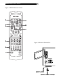
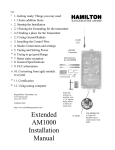
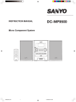
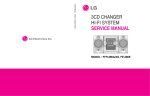
Owner’s Manual
RX-975
AM/FM Stereo Receiver
RX-975 AM/FM Stereo Receiver
WARNING:
There are no user serviceable parts inside. Refer all
servicing to qualified service personnel.
WARNING:
To reduce the risk of fire or electric shock, do not
expose the unit to moisture or water. Do not allow
foreign objects to get into the enclosure. If the unit
is exposed to moisture, or a foreign object gets into
the enclosure, immediately disconnect the power cord
from the wall. Take the unit to a qualified service
person for inspection and necessary repairs.
Read all the instructions before connecting or operating the
component. Keep this manual so you can refer to these safety
instructions.
2
Connect the component to the power outlet only with the supplied power supply cable or an exact equivalent. Do not modify
the supplied cable in any way. Do not attempt to defeat grounding and/or polarization provisions. Do not use extension cords.
Do not route the power cord where it will be crushed, pinched,
bent at severe angles, exposed to heat, or damaged in any
way. Pay particular attention to the power cord at the plug
and where it exits the back of the unit.
The power cord should be unplugged from the wall outlet if
the unit is to be left unused for a long period of time.
Immediately stop using the component and have it inspected
and/or serviced by a qualified service agency if:
• The power supply cord or plug has been damaged.
• Objects have fallen or liquid has been spilled into the unit.
Heed all warnings and safety information in these instructions and on the product itself. Follow all operating instructions.
• The unit has been exposed to rain.
Clean the enclosure only with a dry cloth or a vacuum cleaner.
• The unit has been dropped or damaged in any way
You must allow 10 cm or 4 inches of unobstructed clearance
around the unit. Do not place the unit on a bed, sofa, rug, or
similar surface that could block the ventilation slots. If the
component is placed in a bookcase or cabinet, there must be
ventilation of the cabinet to allow proper cooling.
Place the unit on a fixed, level surface strong enough to support its weight. Do not place it on a moveable cart that could
tip over.
Keep the component away from radiators, heat registers, stoves,
or any other appliance that produces heat.
The unit must be connected to a power supply only of the type
and voltage specified on the rear panel of the unit.
• The unit shows signs of improper operation
NOTE TO CATV SYSTEM INSTALLER:
Call the CATV system or antenna installer’s attention to Article 820-40 of the NEC. This provides guidelines for proper
grounding and, in particular, specifies that the cable ground
shall be connected to the grounding system of the building,
as close to the pint of cable entry as practical. See installation diagram.
NOTE:
This equipment has been tested and found to comply with the
limits for a Class B digital device, pursuant to Part 15 of the
FCC Rules. These limits are designed to provide reasonable
protection against interference in a residential installation.
This equipment generates and can radiate radio frequency
energy and, if not installed and used in accordance with the
instructions, may cause interference to radio or TV communications. There is no guarantee that interference will not occur
in a particular installation. If this equipment does cause interference to radio or television reception, which can determined by turning the equipment off and on, try to correct
the interference by one or more of the following measures:
• Reorient or relocate the receiving antenna.
• Increase the separation between the unit and the television tuner.
• Connect the unit to an AC power outlet on a different electrical circuit.
• Consult your authorized Rotel retailer for assistance.
3
English
Figure 1: Controls and Connections
RX-975 AM/FM Stereo Receiver
4
Figure 2: RR-949 Remote Control
31
37
32
33
38
39
34
Figure 3: Antenna Connections
35
36
5
English
Figure 4: Input Connections
RX-975 AM/FM Stereo Receiver
Figure 5: Output Connections
6
English
7
Contents
Figure 1: Controls and Connections
3
Figure 2: RR-949 Remote Control
4
Figure 3: Antenna Connections
4
Figure 4: Input Connections
5
Figure 5: Output Connections
6
About Rotel ........................................... 8
Getting Started ...................................... 8
Unpacking
8
Placement
8
Main Operating Controls ......................... 8
Power Switch
and Standby Switch
8
Remote Sensor
9
Front Panel Display
9
Master Volume
9
Tone Controls
9
Balance Control
9
Headphones Jack
9
PRESET AUTO SCAN Button
[SHIFT] MUTE
11
TV/BAND Button
11
TUNE/PRESET Button
[SHIFT] TV/BAND
11
CH TUNING Buttons
11
INPUT SOURCE Buttons
12
NUMERIC Buttons
12
Rear Panel Connections ........................ 12
Phono Inputs
and Phono Ground
12
CD Inputs
12
Tape Inputs and Outputs
12
VIDEO 1 Inputs/Outputs
12
VIDEO 2 – 5 Inputs
12
TV Monitor Output
12
Speaker Outputs
12
Preamp Inputs/Outputs
13
Antenna Connections ............................ 13
9
AM Loop Antenna
13
MEMORY Button
9
FM Wire Antenna
13
Input Source Buttons
9
AC Power Connections .......................... 14
Speaker Button
and Speaker LEDs
Tuning Controls .................................... 10
AC Input
14
BAND Button
10
TUNING Button
10
AC Convenience Outlet
[USA version only]
14
NUMERIC Buttons: Station Presets
10
Remote External Sensor
14
FREQUENCY DIRECT Button
10
Specifications ....................................... 15
MONO Button
10
Audio
15
Video
15
FM Tuner
15
AM Tuner
15
General
15
RR-949 Remote Control ....................... 11
AUDIO Button
11
Programming the RR-949
11
POWER Button
11
VOLUME Buttons
11
SHIFT Button
11
MUTE Button
11
RX-975 AM/FM Stereo Receiver
8
About Rotel
Getting Started
A family whose passionate interest in music led them to manufacture high fidelity components of uncompromising quality founded
Rotel over 30 years ago. Through the years
that passion has remained undiminished and
the family goal of providing exceptional value
for audiophiles and music lovers regardless
of their budget, is shared by all Rotel employees.
Thank you for purchasing the Rotel RX-975
AM/FM Stereo Receiver. The RX-975 is three
products in one:
The engineers work as a close team, listening to, and fine tuning each new product
until it reaches their exacting musical standards. They are free to choose components
from around the world in order to make that
product the best they can. You are likely to
find capacitors from the United Kingdom and
Germany, semi conductors from Japan or
the United States, while toroidal power transformers are manufactured in Rotel’s own
factory.
Rotel’s reputation for excellence has been
earned through hundreds of good reviews
and awards from the most respected reviewers in the industry, who listen to music every day. Their comments keep the company
true to its goal - the pursuit of equipment that
is musical, reliable and affordable.
All of us at Rotel, thank you for buying this
product and hope it will bring you many hours
of enjoyment.
1. A full-featured audio/video control center for analog audio and video source
components
2. A high-quality AM/FM tuner with 30
station presets, direct access tuning, and
auto-tuning.
3. A high power 2-channel amplifier.
Rotel’s Balanced Design Concept combines
advanced circuit board layout, comprehensive parts evaluation, and extensive listening tests for superior sound and long term
reliability. We are confident that you will enjoy the high performance of your Rotel
RX-975 for years to come.
In addition, the RX-975 includes a universal remote control that is factory programmed
operate the RX-975 and can be programmed
to operate up to seven other components of
your choice, providing the convenience of
whole-system control from a single remote.
Make sure there is enough room behind the
RX-975 for easy hookup. Remember, you are
connecting many other components to this
unit and you’ll probably need more space
than you think.
Don’t stack other objects (components or
other items) on top of the RX-975. Don’t let
water fall into the RX-975 as this could damage delicate circuitry.
Main Operating Controls
We suggest you look over the RX-975’s front
and rear panels before you start connecting other components to it. The following explanations will help you get familiar with the
units connections, features, and controls, with
number references corresponding to the illustrations at the front of this manual.
Most functions are duplicated on the front
panel and on the remote control shipped with
your unit. A few may be available only on
one or the other. When two reference numbers appear, one refers to the location of
the button on the front panel, the other to
the location of the button on the handheld
remote control.
Unpacking
Remove the unit carefully from its packing.
Look for the handheld remote control and
other accessories. Save the packing and box
as it will protect the RX-975 if you move or
need to return it for maintenance.
NOTE:
Placement
STANDBY Switch
Place the RX-975 on a solid, dry, level surface away from direct sunlight, excessive
heat, high humidity, or strong vibrations.
The RX-975 can generate considerable heat
during normal operation. Do not block its
ventilation openings. Allow a minimum of
10 cm (4 inches) of unobstructed open space
around the unit. If installed in a cabinet, make
sure that there is adequate ventilation.
Make sure the RX-975 is close to the other
components in your audio/video system and,
if possible, place it on its own shelf. This will
make initial cable routing, hookup, and any
subsequent system changes easier. It also
minimizes potential interference or heat
buildup from other components.
Front panel controls and displays used
for tuning the AM/FM receiver are described in the next section of this manual.
POWER Switch
and
The RX-975 has two pushbuttons for powering on and off. The POWER switch completely shuts down all of the circuitry, similar in effect to removing the power cord from
the AC outlet. The STANDBY switch deactivates the unit, but preserves power to some
circuits such as those that store memorized
circuits. When in STANDBY mode, a front
panel STANDBY LED indicator lights. The
STANDBY switch is duplicated on the
RX-975's remote.
English
9
In normal operation, use the STANDBY switch
to deactivate the unit when you are finished
listening and leave the POWER switch ON
at all times. This will preserve memory functions.
NOTE:
The STANDBY switch also controls
the rear panel AC outlets. When the RX-975
is in STANDBY mode, the AC outlet is also
off. When the RX-975 is fully functional, the
AC outlet is live.
Remote Sensor
This sensor receives infrared signals from the
handheld remote control. Make sure you do
not accidentally block this sensor with cables
or accessories.
Front Panel Display
The large fluorescent display in the upper
portion of the RX-975 provides status information used in operating the AM/FM receiver (such as station frequency display,
band, preset memory, etc.).
MASTER VOLUME
The MASTER VOLUME control adjusts the
level of all output channels simultaneously.
Rotate the control clockwise to increase the
volume. Rotate counterclockwise to decrease
the volume. MASTER VOLUME buttons are
also available on the RX-975's handheld remote control.
When you adjust the volume, a bar indicator in the display shows the volume setting.
TONE Controls
BASS and TREBLE controls increase and
decrease the audio signal’s low and high
frequency content respectively. Rotate clockwise to increase output in the respective frequency range and counterclockwise to reduce it. The center detent removes each
control from the audio path for maximum
signal integrity.
BALANCE Control
Input Source Buttons
Turn the BALANCE control clockwise to increase the output level of the right channel
speakers. Turn counterclockwise to increase
the output level of the left channel speakers.
The center detent position removes the control
from the circuit and provides equal output
from both left and right channels.
Ten large front panel buttons directly select
an audio or video input source (such as a
CD player, the built-in tuner, a tape recorder,
video sources, etc.) for listening. Push any
of these buttons (or the duplicates on the
handheld remote) to select the desired source.
You will hear this source and, if you have
selected a video source, see its picture on
your TV monitor. The front panel display will
show the current source selection.
HEADPHONES Jack
This jack accepts a standard 1/4 inch stereo headphone plug. Use an adaptor if your
headphones have the smaller mini-plug.
Inserting a headphone plug will automatically disable all speaker outputs.
SPEAKER Button
SPEAKER LEDs
and
The RX-975 provides output connections for
two pairs of speakers: A and B. The SPEAKER
BUTTON controls which pairs of speakers
outputs, if any, are active. A pair of SPEAKER
LED indicators located to the left of the DISPLAY shows the current speaker selection.
Press the SPEAKER button repeatedly to step
sequentially through the four available
speaker options:
• Speakers A active (LED A only lit)
• Speakers B active (LED B only lit)
• Speakers A and B active (both LEDs lit)
• All speakers off (no LEDs lit)
NOTE: Inserting a headphone plug into the
headphone jack disables all speaker outputs, regardless of the SPEAKER button setting.
MEMORY Button
The MEMORY button is used to confirm and
memorize tuner station presets. Its use is
described in detail in the Tuning Controls section of this manual.
TAPE MONITOR Buttons: Two of the INPUT SOURCE buttons have a special function. The TAPE 1 and TAPE 2 MONITOR
buttons activate the audio inputs of a tape
monitor loop consisting of a pair of outputs
and a matching set of inputs. Normally, this
tape monitor loop is used to play a tape deck
connected to these inputs or for real time
monitoring of a recording in progress on an
audio tape deck. Alternatively, the tape
monitor loop could be used to pass a signal to a graphic equalizer and listen to the
processed signal by pressing the corresponding TAPE MONITOR button. An indicator appears in the front panel display when TAPE
2 MONITOR is activated.
RX-975 AM/FM Stereo Receiver
Tuning Controls
The RX-975 features a digital synthesized
AM/FM tuner with 30 station presets. Operation of the tuning functions involves the
use of a row of numeric buttons and five large
buttons below the MASTER VOLUME knob.
BAND Button
The BAND button selects whether the tuner
is in AM or FM mode. Press the button to
toggle back and forth between AM and FM.
A corresponding indicator will light at the
left portion of the front panel display to
confirm your choice and the currently tuned
station frequency will be shown.
TUNING Button
This rocker switch (or pair of buttons labeled
CH UP/DOWN on the remote control) provides two different tuning functions, depending on the mode of operation.
In the normal FREQUENCY TUNING
mode, press a TUNING button and release
to manually jump to the next station frequency,
regardless of whether or not a station is
broadcasting on that frequency. For auto scan
tuning, press and hold the TUNING button
for approximately one second. An AUTO indicator will appear in the front panel display and the tuner will begin automatically
scanning up or down through the frequencies until the next available station is detected.
If this is not the desired station, repeat the
automatic tuning procedure to find the next
station. Weak stations will be skipped during auto tuning.
In the PRESET TUNING mode, press a
TUNING button and release to jump to the
next memorized station preset. Switch between FREQUENCY and PRESET tuning
modes by pressing the SHIFT button and then
the BAND/TV button on the remote control.
A PRESET indicator appears in the display
when PRESET TUNING is activated.
NOTE:
Several indicators in the front panel
display assist tuning. A large display shows
the tuned frequency and increases or decreases during tuning. A TUNED indicator
lights when a sufficiently strong signal is
received. A ST indicator lights when a stereo FM signal is received.
10
NUMERIC Buttons: Station
Presets
The RX-975 can store up to 30 station presets for recall at any time using the NUMERIC
buttons. To memorize a station:
1. Tune to the desired station, AM or FM.
2. Press the MEMORY button on the front
panel. A MEMORY indicator will flash
for five seconds in the front panel display.
3. While the MEMORY indicator is flashing,
press the number of the preset where you
wish to store the station frequency. For
example, to memorize the station as
preset 3, press the 3 button. To memorize preset 15, press the 1 button followed
by the 5 button.
4. A previously stored frequency is erased
from memory when a new frequency is
memorized for the same preset number.
To tune to a previously memorized
station, just press the preset number
on the NUMERIC buttons. For example,
to tune to preset 3, press the 3 button. To
tune to preset 15, press the 1 button and
then press the 5 button.
NOTE: If the TUNER is not already the selected INPUT SOURCE, selecting a station
preset will automatically switch to the
TUNER input and tune the memorized station.
The NUMERIC buttons can also be used for
direct access tuning (see below).
2. Enter the first digit of the station frequency
using the NUMERIC buttons. The digit will
appear in the frequency display and the
second bar will flash. Enter the remaining digits of the frequency. When all of
the digits have been entered, the tuner
will automatically tune to the displayed
station frequency.
NOTE: On the USA version only, pressing
1 in the FM mode will enter 10 as the
digit in the frequency display. On the European version, it is necessary to press 1
and then 0 to enter 10. For US FM stations, press only one digit following the
decimal point as shown in the first example below. For European FM stations,
press two digits following the decimal
point as show in the second example.
EXAMPLES:
(USA FM) 87.50MHz
Press 8>7>5
(Europe FM) 87.50MHz Press 8>7>5>0
(all AM) 1610kHz
Press 1>6>1>0
MONO Button
The MONO button changes the FM mode
from stereo reception to mono reception. In
stereo mode, a stereo signal will be heard
if the station is broadcasting a stereo signal and there is sufficient signal strength. A
stereo indicator will light in the front panel
display. In mono mode, a mono signal will
be heard even if the station is broadcasting
a stereo signal.
NOTE:
FREQUENCY DIRECT Button
If you know the frequency of the desired
station, you may tune it directly using the
FREQUENCY DIRECT button and the NUMERIC buttons.
1. Press the FREQUENCY DIRECT button to
change the NUMERIC buttons from station preset to Direct Access mode. The
station frequency in the front panel display will change to a series of four bars,
representing the digits of a station frequency, with the first bar flashing.
Switching to mono mode can be a
useful way to improve the reception of weak
or distant FM signals. Less signal strength
is required for clean mono reception than
for stereo reception.
English
11
RR-949 Remote Control
The RX-975 includes a handheld remote
control that does far more than operate the
RX-975. The RR-949 is a full-function programmable remote control that can operate up
to 8 audio/video components.
A separate manual, included with the remote,
gives detailed information on programming
and using the RR-949 to replace all of the
remote controls in your system. This section
is intended to provide only that information
which pertains to the use of the RR-949 to
operate the RX-975.
NOTE:
Many functions duplicate the RX-975
front panel controls and are listed here only
for your reference. Please refer to the previous Front Panel Controls section of this
manual if you need additional information.
AUDIO Button
To operate the RX-975 with the remote, make
sure that the AUDIO mode is active by pressing the AUD button on the remote before you
start. If it is active, pressing command keys
on the RR-949 will cause the AUDIO button
to flash red. Once the AUDIO mode is active, it will stay active unless you press one
of the other DEVICE buttons to control a different component.
Programming the RR-949
The RR-949 is preprogrammed from the
factory to operate the RX-975. Should the
AUDIO command set on your RR-949 not
operate the RX-975, it’s possible that the
programming has been inadvertently
changed. To program the remote to
operate the RX-975, set the AUDIO
Code = 001:
1. Press the AUDIO button at the top of the
remote while simultaneously pressing the
MUTE button and hold both for at least
one second. The AUDIO button will light
in red for 20 seconds, indicating that you
have entered the program mode. The next
step must be done within this 20 second
period, or the RR-949 will revert to its
standard operating mode.
2. Use the NUMERIC buttons to enter the
3-digit code (001) for the RX-975 – press
0, then 0, then 1. The AUDIO button will
flash each time you enter a digit.
3. Store the code number by pressing the
corresponding AUDIO button again. The
button will blink twice to confirm the storage of the code in memory.
POWER Button
Duplicates the function of the STANDBY
switch on the front panel. Press to activate
the RX-975. Press again to deactivate. The
main POWER button on the front panel must
be in the ON position for the remote standby
function to operate.
VOLUME Buttons
A pair of buttons which duplicate the function of the front panel volume control. Press
VOLUME UP to increase the volume and press
VOLUME DOWN to decrease the volume.
SHIFT Button
Used to access secondary functions on several RR-949 buttons. Press the SHIFT button
and then the desired button.
MUTE Button
Push this button once to turn the sound off.
A mute indication will appear in the front
panel display. Press the MUTE button again
to restore previous volume levels.
PRESET AUTO SCAN Button
[SHIFT] MUTE
This shift function activates a PRESET SCANNING feature. Press the SHIFT button and
then the MUTE button to scan through all
memorized station presets, playing each for
five seconds before moving to the next. To
stop the station scanning on the desired station preset, press the MUTE button again.
TV/BAND Button
Duplicates the AM/FM button on the front
panel. Toggles between AM and FM modes.
TUNE/PRESET Button
[SHIFT] TV/BAND
The TUNE/PRESET button toggles between
FREQUENCY TUNING mode (the CH TUNING buttons advance to the next station frequency) and PRESET TUNING mode (the CH
TUNING Buttons advance to the next memorized station preset). To change modes, press
the SHIFT button and then the TV/BAND button. A PRESET indicator in the front panel
DISPLAY will light when the PRESET mode
is active.
CH TUNING Buttons
A pair of buttons, labeled CH UP/DOWN,
which duplicates the functions of the front
panel TUNING button.
In the normal FREQUENCY TUNING
mode, press a CH button and release to
manually jump to the next station frequency,
regardless of whether or not a station is
broadcasting on that frequency. For auto scan
tuning, press and hold the CH button for approximately one second. An AUTO indicator will appear in the front panel display and
the tuner will begin automatically scanning
up or down through the frequencies until the
next available station is detected. If this is
not the desired station, repeat the automatic
tuning procedure to find the next station.
Weak stations will be skipped during auto
tuning.
In the PRESET TUNING mode, press a
CH button and release to jump to the next
memorized station preset. Switch between
FREQUENCY and PRESET tuning modes by
pressing the SHIFT button and then the
BAND/TV button on the remote control. A
PRESET indicator appears in the display when
PRESET TUNING is activated.
RX-975 AM/FM Stereo Receiver
INPUT SOURCE Buttons
Two rows of buttons duplicate the function
of the ten INPUT SOURCE buttons on the front
panel. Select an input source by pressing
the appropriate button. The AUX 1 and AUX
2 buttons correspond to the front panel
VIDEO 4 and VIDEO 5 buttons.
NUMERIC Buttons
Ten numeric buttons, labeled 0 through 9,
duplicate the function of the NUMERIC buttons on the front panel. Selects memorized
station presets.
Rear Panel Connections
The RX-975 provides rear panel connections
for five video sources, three audio sources,
and a phono input for use with a turntable.
These connections include standard RCA
audio inputs and outputs plus composite video
inputs and outputs.
The RX-975 includes two pairs of speaker
connections for the built-in power amplifier
as well as RCA preamp outputs for use with
external amplifiers. In addition, a composite video output connects the unit to your TV
monitor.
NOTE:
DO NOT plug any system component into an AC source until system hookup
is complete and you are confident that all
component-to-component connections have
been properly made.
All video cables should have a 75
ohm impedance rating. Although conventional audio interconnects will pass a
video signal, their construction and limited
bandwidth impose a performance penalty
because, in part, they do not adhere to the
75 ohm standard.
When making signal connections, make sure
that you always preserve proper channel consistency, i.e. connect LEFT channels to LEFT
channel jacks and RIGHT channels to RIGHT
channel jacks. All RCA-type connections on
the RX-975 follow these standard color codes:
Left audio: RCA jack with white inset
Right audio: RCA jack with red inset
Video: RCA jack with yellow inset
12
Connect your audio-only source components
to these RCA inputs and outputs:
Connect the RCA composite video output
of the VCR to the RCA composite video input
labeled VIDEO 1 PLAY.
Phono Inputs
Ground
Hookup the VIDEO 1 REC video output to
the RCA composite video recording input on
your VCR.
and Phono
Connect the left and right output cables of
a turntable to this pair of RCA inputs. Connect the ground wire from your turntable to
the phono ground lug, labeled GND.
CD Inputs
Connect the left and right analog outputs from
a CD player to the RCA input jacks labeled
CD.
Tape Inputs and Outputs
The RX-975 provides two sets of audio tape
connections labeled TAPE 1 and TAPE 2. Each
has a pair of inputs and a pair of record
outputs that allow recording on either tape
deck.
VIDEO 2 – 5 Inputs
These four sets of audio/video inputs allow
connection of four additional video components such as a play-only VCR, DVD player,
LaserDisc player, or DSS satellite receiver.
Connect the RCA analog audio outputs of
the first video component to the left and right
RCA analog audio inputs labeled VIDEO 2.
Then, connect the RCA composite video
output of the video source to the corresponding RCA composite connection labeled
VIDEO 2.
Repeat for additional components, using
VIDEO 3, VIDEO 4, and AUX/VIDEO 5.
Connect the left and right analog outputs from
an audio tape deck to the TAPE 1 IN input
jacks. Connect the TAPE 1 OUT output jacks
to the INPUTS on the audio tape deck.
NOTE: Any of the video source inputs may
also be used for an audio-only source. Simply omit the video connection.
Connect a second tape deck to the TAPE 2
connections – the outputs of the tape deck
to the IN jacks on the RX-975 and the OUT
jacks on the RX-975 to the inputs on the tape
deck.
TV Monitor Output
VIDEO 1 Inputs/Outputs
There are groups of connections for up to
five video source components. Each group
includes a pair of RCA analog audio inputs
and a composite video input. One group,
VIDEO 1, also includes a set of record outputs for sending audio and video signals to
a VCR.
Connect your VCR to the VIDEO 1 group
of inputs and outputs. This set of connections
allows recording.
Connect the analog audio outputs of the
VCR to the VIDEO 1 PLAY left and right RCA
audio jacks. Connect the VIDEO 1 REC left
and right RCA audio output jacks to the audio
inputs on the VCR.
The video output of the RX-975 sends the
video signal to your TV monitor. Connect the
TV MONITOR output to an RCA composite
video input on your television monitor. Whatever input source is selected on the RX-975
will appear on screen.
Speaker Outputs
The RX-975 has a built-in stereo amplifier
for driving left and right speakers. There are
two pairs of connections on the back panel
which allow you to connect two pairs of
speakers (A and B) and select them with a
front-panel button.
NOTE: The combined speaker impedance
must be a minimum of 4 ohms. If you are
driving just one pair of speakers (A or B
connections), use speakers with a nominal
impedance of 4 ohms or higher. If you are
driving two pairs of speakers (A and B) simultaneously, use speakers rated at 8 ohms
or higher.
English
13
The back panel speaker connections consist of two groups of binding posts which
accept bare wire or banana type plug connectors (except in the European Community
countries where their use is not permitted).
One group is used for the A speakers; the
other for the B speakers. Each group has a
positive (+) and negative (–) connection for
the right speaker and a positive (+) and
negative (–) connection for the left speaker
Each pair of connectors is color-coded for
polarity: red for the positive connection and
black for the negative connection. All speakers and all speaker wire is also marked for
polarity. It is essential for proper performance
to maintain this polarity at all speaker connections. Always connect the positive terminal
of each speaker to the corresponding red
speaker terminal on the RX-975 and the
negative speaker terminal to the corresponding black connector on the RX-975.
Route the wires from the RX-975 to the speakers. Give yourself enough slack so you can
move the components to allow access to the
speaker connectors. If you are using banana
plugs, connect them to the wires and then
plug into the backs of the binding posts. The
collars of the binding posts should be screwed
in all the way (clockwise). If you are attaching
bare wires directly to the binding posts,
separate the wire conductors and strip back
the insulation from the end of each conductor. Be careful not to cut into the wire strands.
Unscrew the binding post collars. Insert the
wire into the hole in the shaft. Turn the collars clockwise to clamp the wire in place.
NOTE :
Be sure there are no loose wire
strands that could touch adjacent wires or
connectors.
Preamp Inputs/Outputs
The RX-975 provides a pair of variable-level
RCA preamp audio outputs and a pair of
RCA amplifier inputs that allow you to use
external amplifiers in place of, or in addition to, the built-in amplifiers.
NOTE:
The preamp outputs are connected
to power amplifier inputs with metal jumpers in a standard PRE OUT/MAIN IN configuration. To disable the built-in power
amplifiers and use external amplifiers, it will
be necessary to remove these jumpers. Save
them for future use.
To hook up the RCA audio outputs
to an external amplifier, connect a standard
audio cable from each output to the input
of the amplifier channel that will power the
corresponding speaker.
Antenna Connections
The RX-975 requires two antennas to receive
radio signals, one for AM and one for FM.
Most users will get acceptable reception using
the indoor antennas which are supplied with
the RX-975. Instructions for hooking up these
antennas follow.
NOTE:
If you are located a long distance
from the radio transmitters, you may use
an outdoor antenna to improve reception.
Outdoor antenna systems can be dangerous if they are not properly grounded and
should be installed by a professional contractor familiar with the electrical code requirements in your local area.
AM Loop Antenna
The RX-975 includes a loop antenna to receive AM radio signals. Remove this antenna
from the box and locate it near the RX-975.
Connect the 300 ohm twin-conductor wire
from the loop antenna to the pair of screw
terminals labeled AM LOOP, attaching one
wire to each terminal. It does not matter which
wire attaches to which terminal, but make
sure that the connections are solid and that
the two wires do not touch.
You may need to rotate or otherwise reorient the antenna to find the best position.
NOTE:
To use an outdoor antenna, connect
its 300 ohm twin-conductor wire to the AM
terminals in place of the loop antenna, only
after a professional contractor has installed
the antenna system in accordance with local electrical codes.
FM Wire Antenna
The RX-975 includes a wire antenna to receive FM signals. In many countries (including
the USA), this antenna is a T-shaped twinconductor 300 ohm antenna. Remove this
antenna from the box and connect its two
conductors to the two screw terminals on the
supplied 300 ohm to 75 ohm adaptor. Connect the coax plug on the converter to the
FM 75 ohm antenna connector on the
RX-975.
For best reception, unfold the T-shaped wire
antenna. There are eyelets at both ends of
the T, which allow tacking the antenna to a
wall, if desired. Experiment with positioning for best reception.
In some countries, the RX-975 may be supplied with a single wire FM antenna terminated by a 75 ohm coax connector. If your
unit is supplied with this antenna, connect
it directly to the FM 75 ohm antenna connector.
NOTE:
To use an outdoor antenna, connect
its 75 ohm coax lead wire (or 300 ohm
twin-conductor wire and 300 ohm to 75
ohm adaptor) to the FM 75 ohm connector
in place of the indoor wire antenna, only
after a professional contractor has installed
the antenna system in accordance with local electrical codes.
RX-975 AM/FM Stereo Receiver
AC Power Connections
AC Input
Your RX-975 is configured at the factory for
the proper AC line voltage in the country
where you purchased it (120 volts AC, 60Hz
in the US or 230 volts AC, 50Hz in the
European community). The AC line configuration is noted on a decal on the back of
your unit.
Plug the supplied cord into the AC INPUT
receptacle on the back of the unit.
AC Convenience Outlet
[USA version only]
Two AC outlets let you plug a power cord
from a source component or other accessory
into the back of the RX-975 so that it will
be turned on and off automatically. The outlet
is powered whenever the RX-975 is fully
active and off when it is in STANDBY mode.
Remote External Sensor
This 3.5 mm mini-jack receives command
codes from industry-standard infrared receivers (Xantech, etc.) via hard-wired connections. This feature could prove useful when
the unit is installed in a cabinet and the frontpanel sensor is blocked. Consult your authorized Rotel dealer for information on these
external repeaters and the proper wiring of
a jack to fit the mini-jack receptacle.
14
English
15
Specifications
All specifications are accurate at the time of
printing.
Rotel reserves the right to make improvements
without notice.
Rotel and the Rotel HiFi logo are registered
trademarks of The Rotel Co, Ltd., Tokyo, Japan.
Audio
Continuous Amplifier Power:
100 watts/channel
(20–20k Hz, <0.05% THD, 8 ohms)
Total Harmonic Distortion:
<0.05% at rated power
Intermodulation Distortion (60 Hz: 7 kHz):
<0.05% at rated power
Frequency Response:
Line Level: 10 Hz - 70 kHz, ±3 dB
Phono: 20 Hz - 20 kHz, ±1.5 dB
Signal to Noise Ratio (IHF “A” weighted):
92 dB
Input Overload:
Line Inputs: 5 V
Phono Inputs: > 120 mV
Preamplifier Output Voltage:
1.1 V
Input Sensitivity/Impedance:
Line Level: 200 mV/47 kohms
Phono: 3.1 mV/47 kohms
Tone Controls (Bass/Treble):
±8 dB at 100 Hz/10 kHz
Video
Frequency Response:
3 Hz-10 MHz, ± 3 dB
Signal to Noise Ratio:
45 dB
Input Impedance:
75 ohms
Output Impedance:
75 ohms
Output Level:
1 volt
FM Tuner
Usable Sensitivity:
14.2 dBf
50dB Quieting Sensitivity:
20.2 dBf (mono)
45.3 dBf (stereo)
Signal to Noise Ratio (at 65 dBf):
70 dBf (mono)
65 dBf (stereo)
Harmonic Distortion (at 65 dBf):
0.3% (mono)
0.5% (stereo)
Frequency Response:
30 Hz-14 kHz, ± 1.5 dB
Capture Ratio:
2.0 dB
Alternate Channel Selectivity:
47 dB (± 400 kHz)
Spurious Response Ratio:
80 dB
Image Response Ratio:
65 dB
IF Response Ratio:
80 dB
AM Suppression Ratio:
52 dB
Stereo Separation (100Hz/1 kHz/10 kHz):
40 dB/45 dB/35 dB
Output level:
550 mV
Antenna Input:
75 ohms unbalanced
AM Tuner
Sensitivity:
500 µV/m
Selectivity:
25 dB
Image Response Ratio:
35 dB
Signal to Noise Ratio:
40 dB
Output level:
160 mV
Antenna Input:
Loop Antenna
General
Power Consumption:
350 watts
Power Requirements (AC):
120 volts, 60 Hz (USA version)
230 volts, 50 Hz (European version)
Weight:
11.5 Kg/25.4 lb.
Dimensions (W x H x D):
450 x 158 x 400 mm
17 3/4" x 61/4" x 153/4"
The Rotel Co. Ltd.
10-10 Shinsen-Cho
Shibuya-Ku
Tokyo 150-0045
Japan
Phone: +81 3-5458-5325
Fax: +81 3-5458-5310
Rotel of America
54 Concord Street
North Reading, MA 01864-2699
USA
Phone: +1 978-664-3820
Fax: +1 978-664-4109
Rotel Europe
Meadow Road
Worthing, West Sussex BN11 2RX
England
Phone: +44 (0)1903 524 813
Fax: +44 (0)1903 524 831
Rotel Deutschland
Kleine Heide 12
D-33790 Halle/Westf.
Germany
Phone: +49 05201-87170
Fax: +49 05201-73370
082 OMRX-975ENG 042499