1
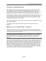
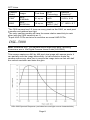
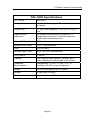
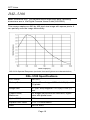
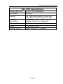
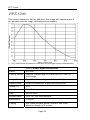
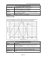
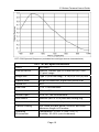
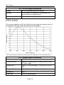
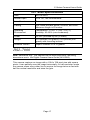
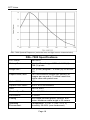
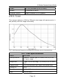
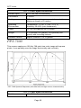
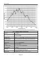
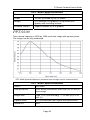
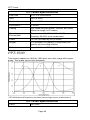
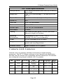
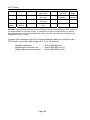
C-Series Cameras
Users Guide
PPT Publication #843-0099 Rev K
Disclaimer
PPT VISION, Inc. makes no representations or warranties for
merchantability or fitness for any particular purpose, as regards PPT
Vision's hardware or software. PPT Vision shall not be liable for errors
contained herein or for incidental or consequential damages in connection
with the furnishing, performance, or use of this publication or its contents.
PPT Vision reserves the right to revise this publication and to make
changes in the content hereof without obligation to notify any person of such
revision or changes.
Under the copyright laws, this publication may not be copied, photocopied,
reproduced, or reduced to any electronic medium or machine-readable
form, in whole or in part, without the prior written consent of PPT Vision.
Telephone:
Facsimile:
Web site:
(952) 996-9500
(952) 996-9501
pptvision.com
Impact, Digital Serial Link, and DSL are trademarks of PPT VISION, Inc.
Copyright © 1997-2012 PPT VISION, Inc. All Rights Reserved
Technical Support
If you have technical questions about the operation of any PPT Vision
products, contact your distributor or PPT Vision.
PPT C-Series Cameras
This document describes digital cameras manufactured by PPT Vision and
Camera Link cameras manufactured by other companies. All the cameras
in this document can be used with PPT’s C-Series machine vision microsystem.
PPT Vision does not support the use of these cameras in any manner other
than described herein.
Table of Contents
Safety Precautions................................................................2
General Information ..............................................................3
Mounting a Camera ..............................................................4
PPT-5700 Remote Head Dimensions ...................................5
Connecting a Camera ...........................................................6
LED Indicator ........................................................................7
Setup and calibration ............................................................7
DSL-5000 .............................................................................8
DSL-5100..............................................................................10
PPT-5200..............................................................................12
PPT-5300..............................................................................13
PPT-5700..............................................................................14
PPT-6200..............................................................................16
DSL-7000..............................................................................17
PPT-7300..............................................................................20
PPT-8200..............................................................................21
PPT-9200..............................................................................23
PPT-9300..............................................................................24
Camera Link Cameras ..........................................................25
Page 1
PPT Vision
Safety Precautions
Read all of the following instructions before setting up your camera. Save
this document for later use.
1.
Follow all warnings and instructions in this manual and in other user
guides shipped with your hardware components.
2.
Do not attempt to disassemble the camera. Do not remove screws
or attachments. There are no user-serviceable parts inside. Refer
servicing to PPT Vision or your local distributor.
3.
All PPT digital cameras connect to the vision device using a
standard Digital Serial Link (DSL) cable (Part # 431-0452-xx). Do
not attempt to use any other cable. (See page 26 for Camera Link
cables.)
4.
This camera is designed for indoor use. Do not expose it to
moisture, including rain or snow, and avoid operating it in wet
areas. Should the camera become wet, turn off the power
immediately. Moisture can damage the camera and create danger
of electric shock. Avoid using the camera when the humidity is
above 80%.
5.
Make sure your camera has enough airflow for proper ventilation.
The maximum safe case temperature during operation is 45° C
(114° F).
6.
Mount the camera body in a fixed position where it will not be
subject to excessive vibration. To reduce stress on the camera
connectors and cable, loop the cable and fasten it to the camera’s
mounting block. Do not crimp or tie the cable tightly with wire ties as
this may damage it internally. The cable’s minimum bend radius is
fifteen times the cable diameter. It is not intended for continuous
flexing or movement.
Page 2
C-Series Camera Users Guide
General Information
PPT's digital cameras digitize images at the camera source and transmit
them directly to the vision system as a digital signal. All PPT cameras
provide 8-bit resolution using internal 10-bit A/D converters and some have
progressive scan shutter exposure (allowing individual pixel readings).
Cameras have a hard-coat finish case that helps eliminate ground loops. All
camera settings (shutter, strobe, partial scan, etc.) are configured using
Impact software and are maintained in the camera’s memory so there are
no physical switches on the cameras.
PPT Vision cameras connect to the vision device with a standard DSL cable
(Part # 431-0452-xx).
All cameras can be used with PPT’s C-Series machine vision microsystems.
Before you install the camera
Carefully remove the camera and cabling from the shipping package and
inspect each item. Save all packing materials so you can repack the camera
in case you need to move or ship it.
Extreme temperature precautions: If your camera arrives in very hot or
cold weather, allow it to reach room temperature before using it. Wait for
any condensation to dry completely before connecting it to the vision
device.
Check the intended installation area to be sure there is enough room for the
camera and any lighting that may be needed. Avoid areas with excessive
heat, vibration, and environmental contaminants. Mount cameras away from
devices that emit large amounts of electromagnetic energy. Be sure that
cables are safely routed away from vehicle and pedestrian traffic. Do not
crimp or tie the cable tightly with wire ties as this may damage it internally.
The cable is not intended for continuous flexing or movement. The cable’s
minimum bend radius is fifteen times the cable diameter.
Page 3
PPT Vision
Camera Dimensions
NOTE: The DSL-5000, DSL-5100, and DSL-7000 cameras in this document
have an older body style. Refer to the Digital Camera Users Guide (8430085) for mounting dimensions.
The camera with a mounting block, but without a lens, weighs 0.44 pounds
(200 grams).
.39 (10.0)
.94 (23.9)
UNITS: inch (mm)
¼”-20 (2)
M5 or #10-32 x .25 (2)
M6 or ¼”-20 (countersunk, inserted
from camera side of block)
.69 (17.5)
Mounting Block and Camera body
Bottom View
2.19 (55.7)
1.88 (47.8)
1.75 (44.5)
Side View
Front View
Mounting a Camera
To mount the digital cameras, attach a mounting block (Part # 381-1114) to
the front of the camera.
Mounting
Screw (M3)
Camera
Mounting
Block
(front side)
Mounting
Ring
Page 4
C-Series Camera Users Guide
1.
Remove the lens from the camera body. Turn the mounting
screw counter-clockwise to loosen the mounting ring.
2.
If desired, insert a fastener through the countersunk hole in the
center of the bracket. Rotate the camera body so the image will
be in the desired orientation when the camera is mounted.
Place the mounting ring over the front of the camera body with
the mounting block facing the rear of the camera. (See diagram
below.)
3.
With the ring held tightly against the camera body, turn the
mounting screw clockwise to tighten the ring and secure it to the
camera. To adjust camera orientation up to five degrees after it
is mounted, loosen the screw slightly, turn the camera body,
then tighten the screw.
4.
Secure the mounting block to a rigid surface for proper stability
and heat transfer. Use fasteners in the pre-threaded holes in
the bottom of the mounting bracket, or through the camera-side
countersunk hole in the center of the bracket. (See Camera
Dimensions on page 4.)
Mounting
Ring
Camera
Body
Top of
image
Camera
Body
LED
Indicator
Mounting
Block
Rear View
Side View
PPT-5700 Remote Head Dimensions
The PPT-5700 camera has a small remote head with a 0.8 meter cable
attached to the camera body with a sixteen-pin connector.
The camera body, remote head, and connecting cable must be mounted in
a fixed position. The cable is not intended for continuous flexing or
movement.
Page 5
PPT Vision
Route the connecting cable away from devices that emit large amounts of
electromagnetic energy, such as electric motors or solenoids. They may
cause interference with image transmission.
Use a lens locking ring (Part # 381-1247) to secure a micro-lens on the
remote head.
ATTENTION: The remote head can be
damaged by electrostatic discharge if it is
disconnected from the camera body.
Remote Head
.75 (19) diameter
UNITS: INCH (mm)
.62 (15.7)
Lens and
Locking Ring
fasten here
5.51 (139.9)
Connecting a Camera
0.8-meter cable
connects to camera
Use only a standard DSL cable (Part # 431-0452-xx) to connect the camera
to the vision device. The maximum allowable cable length is 25 meters (82
feet).
To connect the cable, align the connector with the camera or device
connector, push gently until the cable seats securely, then tighten the
connector screws. To disconnect it, loosen the screws completely, then
grasp the connector and gently pull.
DSL Cable Connector
(431-0452-xx)
NOTE: To reduce stress on the cable and connectors, loop the cable and
fasten it to the camera’s mounting block. Do not crimp or tie the cable tightly
with wire ties as this may damage it internally. The cable is not intended for
continuous flexing or movement. The cable’s maximum bend radius is
fifteen times the cable diameter.
Page 6
C-Series Camera Users Guide
LED Indicator
LED
Indicator
Camera Rear View
The LED Indicator on the end of the camera indicates the camera's
communications and power status.
Indicator Color
Red
Green
Blinking Yellow
Status
The camera is receiving power but cannot detect the
DSL Link carrier. Indicates a damaged cable or bad
connection.
The camera is receiving power and detecting the
DSL Link carrier.
The camera is acquiring images (blinking may not be
visible during fast image acquisition)
Setup and calibration
Use the Impact programs to setup and calibrate the camera with a PPT
vision device. (Refer to the Impact Software Reference Guide.)
Calibration insures that measurements shown in Impact software tools
accurately indicate the inspected object’s measurements. A camera
requires calibration when it is first connected to the vision device, when the
camera-to-subject distance changes, and when the lens is changed. A
calibration target with 0.5, 1.0, and 2.0 mm dot pitches is available from
PPT (Part # 381-1177). Contact PPT for printed versions of targets with
larger pitches.
Light Sensitivity
The following table shows the camera’s relative sensitivity to light.
Camera
CCD
Relative
Imager
Pixel Area
2
Model
Technology
Sensitivity
5200
Sony
ICX 424AL
55 sq um
Page 7
HAD
1
PPT Vision
Camera
Model
Imager
Pixel Area
CCD
Technology
Relative
Sensitivity2
72001
Sony
ICX204AL
21 sq um
HAD
21/55 = 0.38
9200
Sony
ECX274AL
19 sq um
Super
HAD™ (2x)3
2 * 19/55 = 0.7
1
The 7200 camera has 2.5 times as many pixels as the 5200, so each pixel
is smaller and gathers less light.
2
The color camera models will have the same relative sensitivity to each
other (with the 5300 sensitivity as 1).
3
Super HAD CCDs are twice as sensitive as normal HAD CCDs.
DSL-5000
Note: Reference only. This camera has an older style body. Mounting
dimensions are in the Digital Camera Users Guide (843-0085).
This camera captures a 640 by 480 pixel size image with square pixels. It
can partially scan the image horizontally. In half-resolution mode the
camera scans every other line to acquire the image twice as fast with half
the vertical resolution and twice the gain.
DSL-5000 Spectral Response (excludes lens and light source characteristics)
Page 8
C-Series Camera Users Guide
DSL-5000 Specifications
PPT Part #
661-0267
Pick-up Device:
Interline Transfer type CCD with 640 (H) x 480
(V) pixels
Image Size:
⅓” (8.47 mm) diagonal – 4.74 (H) x 3.55 (V)
mm
Capture Rate,
Maximum:
38 images per second full-resolution; 71
images per second at ½ vertical resolution;
higher rates with partial scan
Optical Fill Factor:
60%
Square Pixel Value:
7.4 x 7.4 micrometers
Gain:
50% to 400%
Shutter Open Time:
47 to 192,512 microseconds
Lens Mount:
C mount
Cabling:
DSL cable provides power, controls, and
video. Maximum cable length is 25 meters
Operating
Environment:
Temperature: -5°+45° C (+23°∼114° F)
Humidity: 20~80% (non-condensed)
Power:
12 VDC provided by link (3 Watts)
Weight
0.6 pounds (0.28 kg)
Software version
Impact Software V3.0 or greater
Page 9
PPT Vision
DSL-5100
Note: Reference only. This camera has an older style body. Mounting
dimensions are in the Digital Camera Users Guide (843-0085).
This camera captures a 640 by 480 pixel size image with square pixels. It
can partially scan the image horizontally.
DSL-5100 Spectral Response (excludes lens and light source characteristics)
DSL-5100 Specifications
PPT Part #
661-0317
Pick-up Device:
Interline Transfer type CCD with 640 (H) x 480
(V) pixels
Image Size:
⅓” (8.47 mm) diagonal – 4.74 (H) x 3.55 (V)
mm
Capture Rate,
Maximum:
62 images per second full-resolution; higher
rates with partial scan
Optical Fill Factor:
60%
Square Pixel Value:
7.4 x 7.4 micrometers
Gain:
50% to 400%
Page 10
C-Series Camera Users Guide
DSL-5100 Specifications
Shutter Open Time:
32 to 127,795 microseconds
Lens Mount:
C mount
Cabling:
DSL cable provides power, controls, and
video. Maximum cable length is 25 meters
Operating
Environment:
Temperature: -5°+45° C (+23°∼114° F)
Humidity: 20~80% (non-condensed)
Power:
12 VDC provided by link (3 Watts)
Weight
0.6 pounds (0.28 kg)
Software version
Impact Software V3.0 or greater
Page 11
PPT Vision
PPT-5200
This camera captures a 640 by 480 pixel size image with square pixels. It
can partially scan the image vertically and horizontally.
PPT-5200 Spectral Response (excludes lens and light source characteristics)
PPT-5200 Specifications
Part #
661-0337
Pick-up Device
Interline Transfer type CCD with 640 (H) x 480 (V)
pixel image
Image Size
Type ⅓ (5.92 mm diag) – 4.74 (H) x 3.55 (V) mm
Capture Rate
64 fps full-resolution; higher with partial scan
Optical Fill
60%
Pixel Size
7.4 x 7.4 micrometers
Gain
50% to 400%
Shutter Open
31 to 127,795 microseconds
Lens Mount
C mount
Cabling
DSL cable provides power, controls, and video.
Maximum length is 25 meters
Page 12
C-Series Camera Users Guide
PPT-5200 Specifications
Environment
Temperature: -5°+45° C (+23°∼114° F)
Humidity: 20~80% (non-condensed)
Power
12 VDC provided by link (3 Watts)
Weight
0.31 pounds (140 grams); 0.44 pounds (200 grams)
with mounting bracket
Software
Impact Software V3.0 or greater
PPT-5300
This camera captures a 640 by 480 pixel size color image with square
pixels. It can partially scan the image vertically and horizontally.
PPT-5300 Spectral Response (excludes lens and light source characteristics)
PPT-5300 Specifications
Part #
661-0364
Pick-up Device
Interline Transfer type CCD with 640 (H) x 480 (V)
pixel color image
Image Size
Type ⅓ (5.92 mm diag) – 4.74 (H) x 3.55 (V) mm
Capture Rate
64 fps full-resolution; higher with partial scan
Optical Fill
30%
Page 13
PPT Vision
PPT-5300 Specifications
Pixel Size
7.4 x 7.4 micrometers
Gain
50% to 200%
Shutter Open
31 to 127,795 microseconds
Lens Mount
C mount
Cabling
DSL cable provides power, controls, and video.
Maximum length is 25 meters
Environment
Temperature: -5°+45° C (+23°∼114° F)
Humidity: 20~80% (non-condensed)
Power
12 VDC provided by link (3 Watts)
Weight
0.31 pounds (140 grams); 0.44 pounds (200 grams)
with mounting bracket
Software
Impact Software V6.5 or greater
PPT-5700
This camera captures a 640 by 480 pixel size image with square pixels. It
can partially scan the image vertically and horizontally. It has a small remote
head with a 0.8 meter cable attached to the camera body with a sixteen-pin
connector.
ATTENTION: The remote head can be
damaged by electrostatic discharge if it is
disconnected from the camera body.
Page 14
C-Series Camera Users Guide
PPT-5700 Spectral Response (excludes lens and light source characteristics)
PPT-5700 Specifications
Part #
661-0350
Pick-up Device
Interline Transfer type CCD with 640 (H) x 480
(V) pixel image
Image Size
Type ⅓ (5.92 mm diag) – 4.74 (H) x 3.55 (V) mm
Capture Rate
64 fps full-resolution; higher with partial scan
Optical Fill
60%
Pixel Size
7.4 x 7.4 micrometers
Gain
50% to 400%
Shutter Open
31 to 127,795 microseconds
Lens Mount
External (M15.5 x 0.5) with lens locking ring
Remote Head Cable
0.8 meter cable with 16 pin circular connector
Camera Cabling
DSL cable provides power, controls, and video.
Maximum length is 25 meters.
Operating
Environment
Temperature: -5°+45° C (+23°∼114° F)
Humidity: 20~80% (non-condensed)
Page 15
PPT Vision
PPT-5700 Specifications
Power
12 VDC provided by link (3 Watts)
Weight
0.31 pounds (140 grams); 0.44 pounds (200
grams) with mounting bracket
Software version
Impact Software V3.0 or greater
PPT-6200
This camera captures a 640 by 480 pixel size image with square pixels. It
can partially scan the image vertically and horizontally.
PPT-6200 Spectral Response (excludes lens and light source characteristics)
PPT-6200 Specifications
Part #
661-0348
Pick-up Device
Interline Transfer type CCD with 640 (H) x 480
(V) pixel image
Image Size
Type ½ (7.92 mm diag) – 6.34 (H) x 4.75 (V)
mm
Capture Rate
64 fps full-resolution; higher with partial scan
Optical Fill
60%
Pixel Size
9.9 x 9.9 micrometers
Page 16
C-Series Camera Users Guide
PPT-6200 Specifications
Gain
50% to 400%
Shutter Open
31 to 127,795 microseconds
Lens Mount
C mount
Cabling
DSL cable provides power, controls, and video.
Maximum length is 25 meters
Operating
Environment
Temperature: -5°+45° C (+23°∼114° F)
Humidity: 20~80% (non-condensed)
Power
12 VDC provided by link (3 Watts)
Weight
0.31 pounds (140 grams); 0.44 pounds (200
grams) with mounting bracket
Software version
Impact Software V3.0 or greater
DSL-7000
Note: Reference only. This camera has an older style body. Mounting
dimensions are in the Digital Camera Users Guide (843-0085).
This camera captures an image with a 1024 x 768 pixel size with square
pixels. It can partially scan the image horizontally. In half-resolution mode
the camera scans every other line to acquire the image twice as fast with
half the vertical resolution and twice the gain.
Page 17
PPT Vision
DSL-7000 Spectral Response (excludes lens and light source characteristics)
DSL-7000 Specifications
PPT Part #
661-0310
Pick-up Device :
Interline Transfer type CCD with 1024 (H) x
768 (V) pixels.
Image Size :
1/3” (6 mm) diagonal – 5.8 mm (H) x 4.92 mm
(V)
Capture Rate, Max:
16.5 full-resolution images per second; 28
images per second at ½ vertical resolution;
higher rates with partial scan
Optical Fill Factor :
55%
Square Pixel Value :
4.65 x 4.65 micrometers
Gain:
50% to 400%
Shutter Open Time :
77 to 315,392 microseconds
Lens Mount :
C mount
Cabling :
DSL cable provides power, controls, and
video. Maximum cable length is 25 meters
Operating
Environment:
Temperature: -5°+45° C (+23°∼114° F)
Humidity: 20~80% (non-condensed)
Page 18
C-Series Camera Users Guide
Power:
12 VDC provided by link (6 Watts)
Weight
0.6 pounds (0.28 kg)
Software version
Impact Software V3.0 or greater
PPT-7200
This camera captures a 1024 by 768 pixel size image with square pixels. It
can partially scan the image horizontally.
PPT-7200 Spectral Response (excludes lens and light source characteristics)
PPT-7200 Specifications
Part #
661-0338
Pick-up Device
Interline Transfer type CCD with 1024 (H) x 768
(V) pixel image.
Image Size
Type ⅓ (5.92 mm diag) – 4.76 mm (H) x 3.57 mm
(V)
Capture Rate
16.5 full-resolution fps; higher with partial scan
Optical Fill
55%
Pixel Size
4.65 x 4.65 micrometers
Gain
50% to 400%
Page 19
PPT Vision
PPT-7200 Specifications
Shutter Open
77 to 195,580 microseconds
Lens Mount
C mount
Cabling
DSL cable provides power, controls, and video.
Maximum length is 25 meters
Operating
Environment
Temperature: -5°+45° C (+23°∼114° F)
Humidity: 20~80% (non-condensed)
Power
12 VDC provided by link (3 Watts)
Weight
0.31 pounds (140 grams); 0.44 pounds (200
grams) with mounting bracket
Software version
Impact Software V3.0 or greater
PPT-7300
This camera captures a 1024 by 768 pixel size color image with square
pixels. It can partially scan the image horizontally and vertically.
PPT-7300 Spectral Response (excludes lens and light source characteristics)
PPT-7300 Specifications
Part #
661-0367
Page 20
C-Series Camera Users Guide
PPT-7300 Specifications
Pick-up Device
Interline Transfer type CCD with 1024 (H) x 768
(V) pixel image.
Image Size
Type ⅓ (5.92 mm diag) – 4.76 mm (H) x 3.57 mm
(V)
Capture Rate
16.5 full-resolution fps; higher with partial scan
Optical Fill
55%
Pixel Size
4.65 x 4.65 micrometers
Gain
50% to 200%
Shutter Open
77 to 195,580 microseconds
Lens Mount
C mount
Cabling
DSL cable provides power, controls, and video.
Maximum length is 25 meters
Operating
Environment
Temperature: -5°+45° C (+23°∼114° F)
Humidity: 20~80% (non-condensed)
Power
12 VDC provided by link (3 Watts)
Weight
0.31 pounds (140 grams); 0.44 pounds (200
grams) with mounting bracket
Software version
Impact Software V6.6 or greater
PPT-8200
The PPT-8200 camera captures a 1280 by 1024 pixel size image. It has
square pixels and can be fully windowed.
Page 21
PPT Vision
PPT-8200 Spectral Response (excludes lens and light source characteristics)
PPT-8200 Specifications
Part #
661-0339
Pick-up Device
CMOS active pixel sensor with 1280 (H) x 1024
(V) pixel image.
Image Size
Type ⅔ (11 mm diag) – 8.6 mm (H) x 6.9 mm (V)
Capture Rate
22.5 full-resolution fps; higher with partial scan
Optical Fill
50%
Pixel Size
6.7 x 6.7 micrometers
Gain
100% to 400%
Shutter Open
31 to 127,100 microseconds
Lens Mount
C mount
Cabling
DSL cable provides power, controls, and video.
Maximum length is 25 meters
Operating
Temperature: 0°+45° C (+32°∼114° F)
Page 22
C-Series Camera Users Guide
PPT-8200 Specifications
Environment
Humidity: 20~80% (non-condensed)
Power
12 VDC provided by link (2 Watts)
Weight
0.31 pounds (140 grams); 0.44 pounds (200
grams) with mounting bracket
Software version
Impact Software V3.0 or greater
PPT-9200
This camera captures a 1600 by 1200 pixel size image with square pixels.
The image can be fully windowed.
PPT-9200 Spectral Response (excludes lens and light source characteristics)
PPT-9200 Specifications
Part #
661-0349
Pick-up Device
CCD active pixel sensor with 1600 (H) x 1200 (V)
pixel image.
Image Size
Type 1/1.8 (8.8 mm diag) – 7.14 mm (H) x 5.35
mm (V)
Capture Rate
10.6 full-resolution fps; higher with partial scan
Optical Fill
50%
Page 23
PPT Vision
PPT-9200 Specifications
Pixel Size
4.4 x .4.4 micrometers
Gain
50% to 400%
Shutter Open
77 to 161357 microseconds
Lens Mount
C mount
Cabling
DSL cable provides power, controls, and video.
Maximum length is 25 meters
Operating
Environment
Temperature: 0°+45° C (+32°∼114° F)
Humidity: 20~80% (non-condensed)
Power
12 VDC provided by link (2 Watts)
Weight
0.31 pounds (140 grams); 0.44 pounds (200
grams) with mounting bracket
Software version
Impact Software V5.2 or greater
PPT-9300
This camera captures a 1600 by 1200 pixel size color image with square
pixels. The image can be fully windowed.
PPT-9300 Spectral Response (excludes lens and light source characteristics)
PPT-9300 Specifications
Part #
661-0368
Page 24
C-Series Camera Users Guide
PPT-9300 Specifications
Pick-up Device
CCD active pixel sensor with 1600 (H) x 1200 (V)
pixel image.
Image Size
Type 1/1.8 (8.8 mm diag) – 7.04 mm (H) x 5.28
mm (V)
Capture Rate
10.6 full-resolution fps; higher with partial scan
Optical Fill
50%
Pixel Size
4.4 x .4.4 micrometers
Gain
50% to 200%
Shutter Open
77 to 161,357 microseconds
Lens Mount
C mount
Cabling
DSL cable provides power, controls, and video.
Maximum length is 25 meters
Operating
Environment
Temperature: 0°+45° C (+32°∼114° F)
Humidity: 20~80% (non-condensed)
Power
12 VDC provided by link (4 Watts)
Weight
0.31 pounds (140 grams); 0.44 pounds (200
grams) with mounting bracket
Software version
Impact Software V6.6 or greater
Camera Link Cameras
Camera Link is an industry standard connection for digital imaging
equipment. The PPT C-Series conforms to the Camera Link specification
and can use the Camera Link compatible cameras listed here. All cameras
are configured using Impact software (V3.0 or greater).
Mfg.
Model
Adimec
1000m
Adimec
1600m
Adimec
2000m
Basler
A102K
Our Part #
Size
Weight Resolution
(w x h x l)
(w x h)
601-0304
45 x 45 x
185 g 1004 x 1004
75 mm
601-0307 52.5 x 52.5 x 80 250 g 1600 x 1200
mm
52.5 mm x 52.5 250 g 1980 x 1080
mm x 80 mm
601-0303 62 x 62 x 40.2 222 g 1392 x 1040
mm
Page 25
Speed
(fps)
30
17
17
14.8
PPT Vision
Mfg.
Model
Our Part #
Basler
L101K-2K
601-0306
Cohu
7712
601-0302
SVSVistek
SVS4021
MFCP
601-0316
Size
(w x h x l)
62 x 62 x
38.1mm
52.3 x 52 x
78.7 mm
50 x 55 x 43
mm
Weight Resolution Speed
(w x h)
(fps)
285 g 2048
9300
Linescan
lines/sec
340 g 1004 x 1003
30
200 g 2048 x 2048
11.5
NOTES: Camera specifications are provided by camera manufacturers. PPT Vision is
not responsible for changes, errors, or omissions. Refer to manufacturer’s camera
documentation for current specifications. Only Camera Link cameras listed here are
supported by PPT Vision.
Camera Link cameras use one of these standard cables to connect to the
PPT device (xx is the cable length of 2, 5, or 10 meters):
Straight connector...................... Part # 606-0543-xx
Right angle connector up ........... Part # 606-0544-xx-U
Right angle connector down....... Part # 606-0544-xx-D
Page 26
C-Series Camera Users Guide
Page 27