1
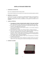
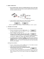
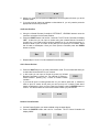
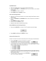
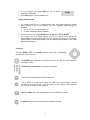
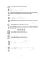
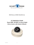
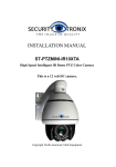
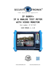
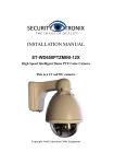
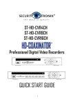
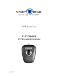
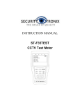
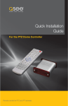
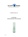
USER MANUAL ST-PTZ-RC Infrared Remote PTZ Controller v1.2 8/22/11 1 PACKAGE CONTENTS This package contains: One ST-PTZ-RC handheld infrared remote controller One PT Dome Controller One connection block One user manual Note: The ST-PTZ-RC handheld infrared remote controller requires 2 AAA batteries (not supplied). The PT Dome Controller requires a 12VDC 1A power supply (not supplied) such as the Securitytronix ST-PS12VDC1A. PRODUCT DESCRIPTION The ST-PTZ-RC is a consumer grade pan, tilt, zoom (PTZ) controller designed for PTZ dome cameras. The ST-PTZ-RC comes with one PT Dome controller allowing PTZ control of up to 255 PTZ cameras. SPECIFICATIONS ST-PTZ-RC Specifications (Typical) 1. Communications Protocol RS-485 2. Baud Rate 1200, 2400, 4800, 9600BPS 3. Camera Protocol PELCO-D, PELCO-P 2 AAA batteries for handheld remote (not supplied) 12VDC 1A power supply for PT Dome Controller (not supplied) 4. Power IMPORTANT NOTE PTZ controllers are designed to perform a wide variety of PTZ camera control functions. However, the utility of any PTZ controller is highly dependant upon the particular PTZ camera to be controlled as each camera has not only its own functions but specific methods of how those native functions are accessed and managed. Further, a particular PTZ controller’s terminology may differ from that used by a particular PTZ camera. Therefore, it will be necessary for the installer and/or user to consult BOTH the PTZ controller and PTZ camera’s user manuals to ensure proper set-up, configuration and application. v1.2 8/22/11 2 INSTALLATION AND OPERATION 1. UNPACKING and HANDLING Each unit is shipped assembled and factory tested. Ensure that all accessories are removed from the container before discarding packing material 2. MECHANICAL INSPECTION Inspect the front and rear of the equipment for shipping damage. Make sure the equipment is clean, and no connectors are broken, damaged, or loose. If equipment appears to be damaged or defective please contact your distributor or Securitytronix at 1-610-429-1511 for assistance. 3. SPECIAL ATTENTION a. The installer must comply with electrical safety standards. There must be sufficient space between the PT Dome Controller and the camera’s communication and power lines, power supplies and video lines and any high voltage equipment and/or cables. b. Do not open up or dismantle the ST-PTZ-RC or the PT Dome Controller’s cases. There are no serviceable parts inside the unit. c. Do not install ST-PTZ-RC or the PT Dome Controller in an environment where the temperature is above 104° F. d. Do not install the ST-PTZ-RC or the PT Dome Controller in a damp environment. e. Only use a dry cloth to clean the units. If there is dirt that is difficult to remove wipe gently with a mild detergent. Never use strong or abrasive detergents. f. A minimum 12VDC 1A power supply must be used. AC power cannot be applied. Using an AC or other incorrect power supply will damage the unit. The SecurityTronix ST-PS12VDC1A power supply is recommended. g. Only qualified installers are allowed to install, test and disassemble the ST-PTZ-RC and the PT Dome Controller. h. As the ST-PTZ-RC and PT Dome Controllers are sensitive devices any shock or collision to the units or shaking of the units will cause damage and void the warranty. 4. PRODUCT PICTURES 3 5. WIRING CONNECTIONS a. Per the diagram below, connect an unshielded twisted pair (UTP) control cable between the PTZ dome camera and the PT Dome Controller using the PT Dome Controller’s connection block. Be sure the connection polarities at the camera and the PT Dome Controller are the same. b. Connect a 12VDC 1A power supply to the PT Dome Controller’s power port. c. After the PT Dome Controller is powered on the unit will display A001 P001 or A refers to “address” so A001 = address 1. P refers to “preset point” so P001 = preset 1. 6. SETTINGS and FUNCTIONS Set Target Camera Protocol and Baud Rate a. Press the Infrared Remote Controller’s DISP one time. The UO 18 PT Dome Controller’s screen will display the current firmware version (in this case version 18). b. Press the DISP one more time and the PT Dome Controller’s screen will display the current camera protocol d -24 and baud rate. The first letter indicates the protocol where d is for PELCO-D and p is for PELCO-P. The last two digits indicate the current baud rate where 12 = 1200BPS, 24 = 2400BPS, 48 = 4800BPS and 96 = 9600BPS. c. If the settings need to be changed press SETUP. The protocol may be changed by using the Infrared Remote Controller’s UP/DOWN buttons and the baud rate via the LEFT/RIGHT buttons. Select the desired protocol and/or baud rate then press ENTER to save and confirm. The ST-PTZ-RC default protocol and baud rate settings are PELCO-D at 2400BPS. Set Target Camera Address a. Press the Infrared Remote Controller’s CAM button to go to the address command mode. This command will select your target camera. b. In this mode you can input a number by pressing any Infrared Remote Controller’s numeric key. For example, pressing key A001 1 will set the target camera address as c. If you want to input a number greater than 10, you need to press the -/-- buttons to enter a “plus 10” mode. At this point you can input up to 3 numbers. Press the C button to backspace. Once you have input the numbers press the ENTER button to confirm. 4 A- - - A- 26 d. Within any mode you can press the ESC button and the system will return you to the address mode. e. If you only want to change an address number below 10, you only need to press the appropriate numeric key one time. Set Preset Position a. Using the Infrared Remote Controller’s LEFT/RIGHT, UP/DOWN buttons move the camera to a location for the Preset Position. b. Press the PRSET button and hold for 3 seconds. The PT Dome Controller will display “SET”. At this time you can input a number using the Infrared Remote Controller’s numeric key. If you need to input a number greater than 10, you need to press the -/-buttons to enter a “plus 10” mode. At this point you can input up to 3 numbers. Press the C button to backspace. Once you have input the numbers press the ENTER button to confirm. P- - - Setc. P001 Repeat steps “a” and “b” for each desired Preset Position. Call a Preset Position a. Press the SHOT button to go to the preset select mode. This command will allow you to select the Preset Position for your camera. b. In this mode you can input a number by press any Infrared P001 Remote Controller’s numeric key. For example, P refers to “ Preset Position” pressing key 1 refers to Preset Position number 1. c. If you want to input a number greater than 10, you need to press the -/-- buttons to enter a “plus 10” mode. At this point you can input up to 3 numbers. Press the C button to backspace. Once you have input the numbers press the ENTER button to confirm. The camera will then move to the Preset Position you just entered. P- - - P-32 Delete a Preset Position a. Call the Preset Position your want to delete using the steps above. b. Press the DELETE button and hold for 3 seconds. The PT Dome Controller will display “CLR-”. P-12 CLr- 5 Set HOME Position a. Setting the HOME position is very similar to setting Preset Positions. b. Using the LEFT/RIGHT and UP/DOWN buttons move the camera to the desired Home Position. c. Press PRESET and hold for 3 seconds. d. Press HOME followed by ENTER to confirm. Set A and B Limiting Positions a. Setting the A and B Limiting Positions is very similar setting Preset Positions and the HOME position. b. Using the LEFT/RIGHT and UP/DOWN buttons move the camera to the desired A Position. c. Press PRESET and hold for 3 seconds. d. Press A followed by ENTER to confirm. e. Repeat the above steps for the B Limiting Position. Delete HOME and A and B Limiting Positions a. Press and hold DELETE for 3 seconds. The PT Controller’s screen will display CLrb. Press HOME, A or B followed by ENTER to confirm. Set Up and Run Pattern Tour A Pattern Tour allows the camera to automatically track a select group of Preset Positions. a. Pressing PATTERN once puts the ST-PTZ-RC into Pattern Track Setup Mode. The PT Dome Controller will display PStA b. In the setup mode up to 16 pre-existing Preset Positions can be selected. For example, if the camera is to tour Preset Position 6, Preset Position 2, Preset Position 3 and Preset Position 8: Press SHOT, 6, ENTER Press SHOT, 2, ENTER Press SHOT, 3, ENTER Press SHOT, 8, ENTER d. It is possible to set both the camera movement speed from one Preset Position to another as well as the dwell time the camera stays on a Preset Position. See “Set Speed” below for details. e. To end the Pattern Track Setup Mode press PATTERN and PStO the PT Dome Controller will display 6 f. To run a Pattern Tour press RUN and the PT Dome Controller’s will display g. Press RUN again to stop the Pattern Tour. PrUN Setting Camera Speed a. For camera travel time (i.e., camera rotation from one Preset Position to another either manually or by running Pattern Tour) four separate speed settings are available: S1 = 8, S2 = 40, S3 = 51 and S4 = 63 S1 is the slowest and S4 is the fastest b. Speed can be set by pressing SPEED then S1, S2, S3 or S4 and ENTER c. For Pattern Tour the default settings are 63 for camera travel speed and approximately 8 seconds dwell time (time the camera will remain on a particular Preset Position). Other speed settings may be made during the Pattern Track Setup Mode described above. Functions The UP, DOWN, LEFT, and RIGHT buttons control the corresponding movement of the PTZ camera. The ENTER button serves as a movement “stop” key. It is also a “confirm” key when inputting a number. Numeric keys 0 through 9 are number input buttons. The C button is to backspace during number input. The -/-- button is to enter into the “plus 10” mode if you want to enter a number greater than 10 (from 0 to 255). It can also place you into “normal” mode where you can only input numbers from 0 through 9. Pressing the ESC button will put the system into the address input mode. The CAM button places the system into the address input mode. 7 The SHOT button calls the desired Preset Position. HOME is for a Home Preset Position. A and B are Preset Positions that can serve as Left and Right Limiting Positions allowing the camera to automatically scan between the two positions. The PRESET button is to set a preset point. The DELETE button is to clear a preset point. Each of these keys needs to be pressed and held for 3 seconds to achieve the desired function. Pressing AUTO puts the system into auto cruise mode. Pressing SPEED sets the speed of the target camera’s movement. S1 through S4 are shortcut keys for speeds: S1 = 8, S2 = 40, S3 = 51, S4 = 63 with S1 the slowest and S4 the fastest. Pressing FOCUS + focuses the target camera far. Pressing FOCUS – focuses the target camera near. Pressing IRIS OPEN opens the target camera’s iris. Pressing IRIS CLOSE closes the target camera’s iris. Pressing ZOOM + zooms the target camera wide. Pressing ZOOM - zooms the target camera near (telephoto). Pressing PATTERN starts / stops pattern learning (Pattern Tour Setup) Pressing RUN runs a Pattern Tour. 8 Pressing DISP displays the system’s software version. Pressing SETUP allows the configuring of the ST-PTZ-RC’s protocol and baud rate. 7. TROUBLESHOOTING TIPS a. The ST-PTZ-RC is not controlling the camera at all – (i) be sure the R485 connections between the ST-PTZ-RC and the camera are using the same polarities; (ii) check to see if the correct baud rate has been set with the camera; (iii) check to see if the correct protocol has been with the camera. b. The ST-PTZ-RC is communicating with the camera, but certain functions do not work – PTZ controllers are designed to perform a wide variety of PTZ camera control functions. However, the utility of any PTZ controller is highly dependant upon the particular PTZ camera to be controlled as each camera has not only its own functions but specific methods of how those native functions are accessed and managed. Further, a particular PTZ controller’s terminology may differ from that used by a particular PTZ camera. Therefore, it will be necessary for the installer and/or user to consult BOTH the PTZ controller and PTZ camera’s user manuals to ensure proper set-up, configuration and application. c. Additional troubleshooting assistance can be found on-line at www.securitytronix.com in addition to support from Securitytronix sales engineers at 1-610-429-1511. 9