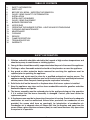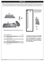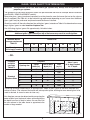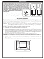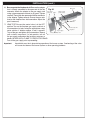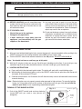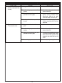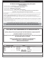
1
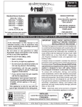
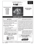
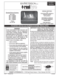
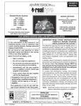
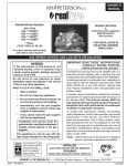
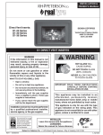
Owner’s
Manual
DESIGN CERTIFIED to
Burner systems:
ANSI Z21.60-2012
CSA 2.26-2012
ANSI Z21.97-2012
CSA 2.41-2012
CAN/CGA-2.17-M87
G45-GL-16/19(N,P)A-SS
G45-GL-18(N,P)A-SS
G45-GL-24(N,P)A-SS
G45-GL-30(N,P)A-SS
G45-GL-36(N,P)A-SS
FOR INSTALLATION IN
SOLID-FUEL BURNING
FIREPLACES
Regulated burner
system for use with
propane or natural gas
FOR USE WITH
FYRE GLASS / FYRE GEMS
G45-GL STAINLESS STEEL BURNER FOR INDOOR OR OUTDOOR USE
Important:
Read this manual carefully before starting installation of the burner system.
CODE AND SUPPLY REQUIREMENTS
The installation and the provisions for combustion
and ventilation air must conform with local codes and
ordinances, or in the absence of local codes, with the
latest National Fuel Gas Code, ANSI Z223.1/NFPA 54,
the Natural Gas and Propane Installation Code, CSA
B149.1, or International Fuel Gas Code.
WARNING
If the information in this manual is not followed
exactly, a fire or explosion may result, causing
property damage, personal injury, or loss of life.
Do not store or use gasoline or other
flammable vapors and liquids in the vicinity
of this or any other appliance.
WARNING
Improper installation, adjustment, alteration,
service, or maintenance can cause injury or
property damage. Read the installation, operating
and maintenance instructions thoroughly before
installing or servicing this equipment.
An LP-cylinder shall not be stored in the
vicinity of this or any other appliance.
WHAT TO DO IF YOU SMELL GAS:
• Do not try to light any appliance.
• Do not touch any electrical switch; do
not use any phone in the building.
• Immediately call the gas supplier from
a neighbor’s phone and follow the gas
supplier’s instructions.
• If you cannot reach the gas supplier,
call the fire department.
Installation and service must be performed
by an NFI Certified or other qualified
professional installer, service agency, or
the gas supplier.
This appliance is designed as an attended
appliance. Adults must be present when the
unit is operating. DO NOT leave this unit burning
when unattended. If this product is left burning
unattended it may cause damage or serious
injury.
INSTALLER: Leave this manual with the appliance.
CONSUMER: Retain this manual for future reference.
The installation of appliances designed for manufactured
home (U.S. only) or mobile home installation must
conform with the Standard CAN/CSA Z240 MH, Mobile
Housing, in Canada, or with the Manufactured Home
Construction and Safety Standard, Title 24 CFR, Part
3280, in the United States, or when such a standard
is not applicable, ANSI/NCSBCS A225.1/NFPA 501A,
Manufactured Home Installations Standard.
11-020
Robert H. Peterson Co. • 14724 East Proctor Avenue • City of Industry, CA 91746
REV 0 - 1212120945
1
L-A2-305
Manuel du
propriétaire
Systèmes de brûleur:
CONCEPTION CERTIFIÉE à
G45-GL-16/19(N,P)A-SS
G45-GL-18(N,P)A-SS
G45-GL-24(N,P)A-SS
G45-GL-30(N,P)A-SS
G45-GL-36(N,P)A-SS
ANSI Z21.60-2012
CSA 2.26-2012
ANSI Z21.97-2012
CSA 2.41-2012
CAN/CGA-2.17-M87
POUR L’INSTALLATION EN
CHEMINÉES BRÛLANTES DE
COMBUSTIBLE SOLIDE*
Système réglé de
brûleur pour l'usage
avec du propane et le
gaz naturel
POUR L'USAGE AVEC
LE VERRE / GEMMES
BRÛLEUR À L'ACIER INOXYDABLE G45-GL POUR L'USAGE D'INTÉRIEUR OU EXTÉRIEUR
Important:
Read this manual carefully before starting installation of the burner system.
AVERTISSEMENT
Si l'information en ce manuel n'est pas suivie
exactement, une incendie ou une explosion
peut résulter, entraînant des dégats matériels,
le dommage corporel, ou des pertes humaines.
Ne stockez pas ou n'employez l'essence ou
d'autres vapeurs et liquides inflammables à
proximité de ceci ou d'aucun autre appareil.
CODEZ ET FOURNISSEZ LES CONDITIONS
Ce brûleur extérieur doit être installé selon des codes
locaux et des ordonnances, ou en l'absence des
codes locaux, avec le plus défunt code national de
gaz de carburant, la norme ANSI Z223.1/NFPA 54, le
code d'installation de gaz naturel et de propane, CSA
B149.1, ou code international de gaz de carburant.
Un LP-cylindre ne sera stocké à proximité
de ceci ou d'aucun autre appareil.
L'installation, l'ajustement, le changement, le service,
ou l'entretien inexact peuvent causer des dommages
ou des dégats matériels. Lisez l'installation, l'opération
et les instructions d'entretien complètement avant
d'installer ou entretenir cet équipement.
AVERTISSEMENT
CE QUI À FAIRE SI VOUS SENTEZ LE GAZ:
• N'essayez pas de n'allumer aucun appareil.
• Ne touchez aucun commutateur électrique ;
n'utilisez aucun téléphone dans le bâtiment.
• Appelez immédiatement le fournisseur de
gaz du téléphone d'un voisin et suivez les
instructions du fournisseur de gaz.
• Si vous ne pouvez pas atteindre le
fournisseur de gaz, appelez les corps de
sapeurs-pompiers.
Cet appareil est conçu comme appareil occupé. Les
adultes doivent être présent quand l'unité fonctionne.
Ne laissez pas ce burning d'unité si sans surveillance.
Si ce produit est laissé sans surveillance brûlant
il peut causer des dommages ou des dommages
sérieux.
L'installation et le service doivent être
assurés par un NFI certifié ou tout autre
installateur professionnel qualifié, agence
de service, ou le fournisseur de gaz.
INSTALLATEUR: Laissez ce manuel avec l'appareil.
CONSOMMATEUR: Maintenez pour la future référence.
L'installation des appareils conçus pour la maison
manufacturée (États-Unis seulement) ou l'installation de
caravane résidentielle doit se conformer au CAN/CSA
standard Z240 MH, logement mobile, au Canada, ou à
la construction et au standard de sécurité à la maison
manufacturés, intitulent 24 CFR, la partie 3280, aux EtatsUnis, ou quand une telle norme ne s'applique pas, à ANSI/
11-020
NCSBCS A225.1/NFPA 501A, installations à la maison
manufacturées standard.
ROBERT H. PETERSON CO. • 14724 East Proctor Avenue • City of Industry, CA 91746
REV 0 - 1212120945
2
L-A2-305
TABLE OF CONTENTS
3
4
5
6
7
7
9
9
10
11
13
13
13
13
13
14
16
SAFETY INFORMATION
PARTS LIST
BEFORE YOU BEGIN - IMPORTANT INFORMATION
GLASS / GEMS QUANTITY DETERMINATION
INSTALLATION
INSTALLING THE BURNER
GLASS / GEMS PLACEMENT
BURNER PREPARATION
NOTES PAGE
OPERATING THE BURNER SYSTEM - LIGHTING AND EXTINGUISHING
CLEANING AND MAINTENANCE
MAINTENANCE
CLEANING
SERVICE
FLAME DESCRIPTION
TROUBLESHOOTING
WARRANTY
SAFETY INFORMATION
1. Children and adults should be alerted to the hazards of high surface temperatures and
should stay away to avoid burns or clothing ignition.
2. Young children should be carefully supervised when they are in the area of the appliance.
3. Clothing or other flammable materials should not be placed on or near the appliance.
4. Any guard or other protective device removed for servicing the appliance must be
replaced prior to operating the appliance.
5. Installation and repair must be done by a qualified professional service person. The
appliance must be inspected before use and at least annually by a qualified professional
service person. More frequent cleaning may be required as necessary.
6. Solid fuels shall not be burned in a fireplace where this burner system is installed.
7. Keep the appliance area clear and free from combustible materials, gasoline and other
flammable vapors and liquids.
8. The burner assembly must be replaced prior to the appliance being put into operation
if it is evident that the burner assembly is damaged. Contact your local dealer for
replacement parts.
9. A fireplace screen must be in place when the system is burning. Provisions for adequate
combustion air must be maintained. Unless other provisions for combustion air are
provided, the screen shall have an opening(s) for introduction of combustion air.
Combustion air is adequate when all flames curl into the fireplace and away from the
screen. When a glass fireplace enclosure (door) is used, leave the doors fully open when
the system is in operation.
REV 0 - 1212120945
3
L-A2-305
PARTS LIST
Before installation, check that your gas burner system is complete. See the PARTS LIST below. If any parts
are missing or damaged, contact your Real-Fyre® dealer before installing or using the burner. Be sure
you know the model and size of your set when ordering options or replacement parts and accessories.
4
Replacement parts
can be ordered from
your local dealer.
3
5
2
1
6
All drawings & photos in this manual are not to scale.
ITEM
DESCRIPTION
QTY
1.
Burner pan and valve assembly
1
2.
Handle extension
1
3.
Separator screen
1
4.
Connector kit (with adapter)
1
5.
or
Select sand granules (natural gas only)
Lava granules (propane gas only)
1
6.
Damper clamp
1
REV 0 - 1212120945
4
Fyre glass / Fyre gems are purchased
and packaged separately. Quantity
will vary, depending on selection.
Glass and gems are available in
various colors; contact your dealer
for further details.
L-A2-305
BEFORE YOU BEGIN - IMPORTANT INFORMATION
Before You Begin, review the information and
safeguards below about the installation and operation
of the Real-Fyre® burner system.
Fig. 5-1
Fireplace dimensions
Check to be sure that the fireplace meets the venting
and construction requirements for the installation
of the burner system.
Rear
width
THIS BURNER IS DESIGNED FOR USE WITH
PROPANE OR NATURAL GAS. Never use natural
gas in a burner system designed for use with propane
gas and never use propane gas in a burner designed
for natural gas.
Depth
Front
width opening
This product is not recommended for use in
temperatures below 32°F.
The fireplace must have a gas supply line that has
been installed by a qualified technician in accordance
with all local codes. The gas supply line must have a
½" minimum interior diameter. If the gas line to the
fireplace is longer than 20', a larger diameter line may
be necessary.
Be sure the burner system is properly sized for the
fireplace. Improper sizing may negatively impact the
proper drafting of the fireplace. Fig. 5-1 illustrates the
critical dimensions of the firebox.
Be sure to clean the fireplace floor of any ashes or other
foreign materials. It is recommended that the fireplace
and chimney be examined and cleaned by a chimney
sweep or other qualified person before you install the
burner system, and annually thereafter.
This burner system must be installed by an NFI
Certified or other qualified professional installer.
The burner system is to be installed only in a solid-fuel
burning fireplace with a working flue and constructed
of noncombustible material. The fireplace must have
an open damper. The chimney must be free of any
obstructions.
Min. Fireplace Dimensions
Burner
size
Width
Required Gas Pressure: The minimum inlet gassupply pressure for the purpose of input adjustment
is 5" for natural gas and 10" for propane gas. The
maximum inlet gas-supply pressure for this burner is
10.5" for natural gas and 13" for propane gas.
Testing the Gas Supply System: The burner system
and its individual shut-off valve must be disconnected
from the gas supply piping system while performing any
tests of the piping system at pressures in excess of ½
psig (3.5 kPa). The burner system must be isolated from
the gas supply piping system by closing its individual
manual shut-off valve during any pressure testing of
the gas supply piping system at test pressures equal
to or less than ½ psig (3.5 kPa). This is accomplished
by closing the gas supply line valve, which is required
by NFPA 54, section 5.54.
BTU
Depth Height
Front* Rear
NAT.
L.P.
16/19"
26"
20"
12"
18"
35k
28k
18"
28"
22"
12"
18"
65k
40k
24"
34"
28"
12"
18"
75k
60k
30"
40"
34"
12"
18"
85k
70k
36"
46"
40"
12"
18"
95k
80k
Height
* This required width allows for centering of the system.
Note: Rear width is at corresponding depth.
Minimum Free Opening Area of Chimney Damper for Venting (sq. in.)
For Factory-Built Fireplaces *
Chimney
Height
15' (min.)
20'
30'
16/19"
18"
24"
30"
36"
22
20
18
41
37
33
47
43
38
53
48
43
60
54
48
* For Masonry-Built Fireplaces; add 4 sq. in. to amount shown.
Important:
REV 0 - 1212120945
For safe operation and proper performance of this product and to comply with certification, listings,
and building code acceptances, use ONLY Peterson Real-Fyre® controls, parts, and accessories
that have been specifically listed or certified for use with this burner system. Use of other controls,
parts, or accessories is prohibited and will void all warranties, certifications, listings, and building
code approvals, and may cause property damage, personal injury, and loss of life.
5
L-A2-305
GLASS / GEMS QUANTITY DETERMINATION
CAUTION: Sand granules
granules are
arefor
foruse
usewith
withnatural
natural
gas
gas
systems
systems
only.
only.
Always
Always
useuse
vermiculite
lava granules
granules
for
for propane
propane
gasgas
systems.
systems.
The granules that come with the burner system are pre-measured and must be used per these instructions
(see GLASS / GEMS PLACEMENT section).
Decorative glass / gems (purchased separately) must be placed to cover the burner (but not on the valve or
pilot, if equipped). See Table 6-1 for the minimum bag requirement depending on your burner size. Additional
glass / gems may be purchased and placed around the burner if desired.
Should you wish to fill the entire fireplace floor with glass / gems; instead use Table 6-2 to determine how many
bags of glass / gems to order based on fireplace size.
One 10-lb. bag of glass / gems fills approximately 144 cubic inches.
CAUTION: When covering the burner with glass / gems; do not exceed 1" above the top of the burner.
Additional glass / gems directly on top of the burner may result in unsafe ignition.
Minimum burner
coverage requirement
Table 6-1
Glass / gem
10 lb. bag(s) needed
Burner size
16/19
18
24
30
36
42
48
60
1
1
1
1
2
2
2
3
- OR Fireplace
complete
coverage
Table 6-2
Fireplace
Opening size
28"
36"
Standard
Fireplace Sizes 32" see-thru
42"
50"
Center
width (in.)
Front to back
depth (in.)
Area
(sq. in.)
Glass / gems
10 lb. bags needed
for 2" depth
25
16
400
6
540
8
30
23
690
10
31
23
713
10
36
30
828
12
1085
15
1334
19
46
33
These bag quantities listed allow for an approximate 2" depth of glass / gems in the entire fireplace floor,
without a burner. (The volume of the burner will take up some space, allowing for some excess glass to be
used as desired, or stored as extra for later use.)
Your fireplace area can be determined by measuring the
center width of your fireplace in inches and multiplying by
the depth from front to back in inches. You can then use
the area column in the table above to approximate the
number of bags needed.
Center
Width
DEPTH
Depth
6
H
eight
HEIGHT
INSTALLATION
The damper clamp with hex bolt (Fig. 7-1) is provided as a means to prevent
full closure of the damper blade. The clamp is easily attached to most damper
blades with pliers or a wrench, and must be permanently installed. The clamp
is designed to prevent accidental closure of the damper when installed as
illustrated (Fig. 7-2 and Fig. 7-3). Should the clamp not fit, or fail to provide the
permanent vent opening listed in the table found above, have a permanent
stop installed, remove the damper blade, or have
the damper cut to provide the minimum permanent Set screw
opening required.
Note: These are minimum damper opening
specifications. The damper must be completely
opened when operating this gas appliance to
achieve the best ventilation possible.
Damper clamp
Fig. 7-1
Open
Closed
Fig. 7-2
Fig. 7-3
INSTALLING THE BURNER
The Real-Fyre burner system must be installed by a qualified professional service technician. Instructions must
be followed carefully to ensure proper performance and full benefit from the burner system. Check to be sure
the burner system is designed and labeled for the type of gas (natural or propane gas) supplied to the
fireplace. Fireplace floor must be level, clean, and smooth.
WARNING: Failure to position the parts in accordance with these diagrams or failure to use only parts
specifically approved with this appliance may result in property damage or personal injury.
REFER TO THE PARTS LIST WHEN FOLLOWING THESE INSTRUCTIONS.
1. MAKE SURE THE FIREPLACE GAS SUPPLY IS TURNED OFF.
2. Locate the handle extension included with your system. Remove the black ON/OFF control knob from the
burner assemby, attach it to the narrow forked end of the extension, and attach the extension to the valve
stem (that the knob originally was connected to). Reference the figure on the next page and the photos in
the GLASS / GEMS PLACEMENT section for orientation.
3. Locate the gas-supply stub inside the fireplace and remove the cap, if attached (see Fig. 7-4).
CAUTION: When removing the cap, make sure the stub does not turn, loosening the connection inside the wall.
4. Attach the nut end of the flex connector (Item 3) to the adapter found on the regulator behind the valve.
Tighten securely.
5. Place the burner system into the fireplace so that it is centered and the open burner pan faces outward.
Fig. 7-4
Gas line
cap
Gas supply
line stub
7
INSTALLATION (cont.)
6. Be sure gas to the fireplace is off. Remove the adapter
that is loosely connected to the open end of the flex
connector. Attach the adapter to the gas-supply stub
using a pipe compound resistant to all gases. Tighten
securely. Then attach the open end of the flex connector
to the adapter. Tighten securely. Ensure the pan rests
level on the fireplace floor after connection. Adjust the
pan if necessary.
Burner pan
Fig. 8-1
Heat shield
(removed) Ignitor
7. LEAK TEST: Be sure the control valve is in the OFF
position. Turn on the fireplace gas supply, and test at
all connections for leaks using the appropriate soapy
water solution. If bubbles appear, a leak is present.
Turn off the gas and tighten at all connections. Repeat
until no leaks are present. If a leak persists, turn off
the gas supply and contact the local gas company or
dealer. NEVER USE A FLAME TO CHECK FOR LEAKS.
Thermocouple
(under screen)
Spark
wire
Thermocouple wire
To gas supply
Regulator
Safety (ON/OFF) valve
Turn off the gas supply prior to proceeding.
Important:
Heatshields must be in place during operation of the burner system. Overheating of the valve
will cause shut down of the burner system or other operating problems.
8
GLASS / GEMS PLACEMENT
Burner pan
(Pack granules in pan
and around tubes)
Granules up to burner tube
Fig. 9-1
Separator
screen
(If front of screen rises up and does not
rest flat; bend it downward as needed)
Fig. 9-2
Side view
Separator
screen
s
ule
an
Gr oped
sl
Granules level
Burner tubes
Burner pan
Fig. 9-3
Relative to the slope of the
burner; DO NOT exceed a
1" depth of glass (directly
above the burner pan)
1"
Burner pan
Fig. 9-4
BURNER PREPARATION
After hooking up the burner to the fireplace gas supply, the decorative
media (granules and glass / gems) must be added for the burner to
function as designed.
Note: Installation is the same for glass and gems. Glass
shown here. These instructions show sand granules being
used as a base for the glass, but only natural-gas burners
use sand. For propane burners, follow these instructions
using lava granules.
WARNING
The burner and pilot must be OFF (fully extinguished), and all valve
covers must be in place before pouring media onto the burner. It may
also be necessary to temporarily cover the pilot assembly to keep media
out of it during this procedure.
GRANULE PLACEMENT
1. Pour the granules into the pan until they just cover the burner tubes.
Then pack the granules in the pan and around the burner tubes.
Add additional granules as needed to end with the granules level
with the top of the burner tubes. Slope the granules in the front
portion of the pan. See Fig. 9-1 and Fig. 9-3.
2. Place the separator screen over the granules such that the rear
of the screen hooks over the top and back of the burner pan, as
shown in Fig. 9-2 and Fig. 9-3. If the front of the screen rises up
from the floor of the pan, bend it downward as needed.
Note: The screen must correctly rest onto the burner pan. If it sits
too high; remove some of the granules to ensure a proper
fit. DO NOT allow for any granules to be above the screen.
GLASS / GEMS PLACEMENT
CAUTION: Glass pieces may have sharp edges. Be careful handling the
glass. Use hand protection, such as gloves, if necessary.
1. Pour the glass / gems directly on top of the granules and screen
so that the burner pan is covered completely and evenly. Relative
to the slope of the burner; DO NOT exceed a 1" depth of glass
(directly above the burner pan) as shown in Fig. 9-4. DO NOT place
glass directly under the pilot. See Fig. 9-5 and Fig.9-6.
Note: At this stage the burner will function as designed; however,
more glass / gems may be added around the burner for
decorative purposes. If glass / gems are desired behind the
burner pan, they may be left at a lower level than the back
of the pan, as shown in Fig. 9-6, or raised up to or above the
level in the back of the pan.
2. Add additional glass / gems around the burner pan as desired (Fig.
9-6). (Be sure to keep pilot area clear.)
Keep pilot
area clear
Fig. 9-6
Fig. 9-5
9
NOTES PAGE
Please use this page to record any information about your burner system that you may want to have at hand.
10
OPERATING THE BURNER SYSTEM - LIGHTING AND EXTINGUISHING
FOR YOUR SAFETY, READ BEFORE LIGHTING
WARNING:
If you do not follow these instructions exactly, a fire or explosion may result, causing property
damage, personal injury, or loss of life.
A. BEFORE LIGHTING, smell all around the burner
system area for gas. Be sure to smell next to the
floor because some gas is heavier than air and
will settle on the floor.
B. IF YOU SMELL GAS:
• Shut off the gas to the appliance.
• Extinguish any open flame.
• If odor continues, keep away from the
appliance, and immediately call the gas
supplier or fire department.
C. Use only your hand to push in or turn the gas
control knob. Never use tools. If the knob will not
push in or turn by hand, don’t try to repair it. Call
a qualified service technician. Force or attempted
repair may result in fire or explosion.
D. Do not use the burner system if any part has been
underwater. Immediately call a qualified service
technician to inspect the burner system and to
replace any part of the control system and any
gas control that has been underwater.
LIGHTING THE BURNER SYSTEM
1. After you have finished checking for leaks, ensure that the unit is turned completely off by pushing in the
ON/OFF control knob and turning clockwise toward OFF until you reach a stop.
2. Turn the ON/OFF control knob counter-clockwise to the ON position. DO NOT PUSH KNOB IN!
Note: You should not hear or smell any gas at this point.
3. Wait five (5) minutes to clear out any gas. Smell for gas, including near the floor. If you smell gas, stop
and follow step B of the safety information above. If you don’t smell gas, go to the next step.
4. LIGHTING INSTRUCTIONS
a. Press and hold in the electronic ignitor button. The ignitor will spark with a rapid clicking noise.
b. While holding in the electronic ignitor, push in the ON/OFF control knob to open the valve. Burner will
now ignite at the maximum BTU input.
c. Continue to hold knob for 10-15 seconds; this will allow the safety valve to activate and the main burner
to remain burning.
Note: Electronic igniter may not properly operate when exposed to high moisture. To manually light the
burner, lay a long-stem match on the surface of the embers near the gas inlet (do not hold the
match in your hand) or use a lighted long necked butane lighter.
TURNING OFF THE BURNER SYSTEM
Fig. 11-1
1. Push in the ON/OFF control knob and turn clockwise
toward OFF until you reach a stop (burner will
extinguish).
11
Electronic ignitor
On/Off
control
knob
ACTIONNANT LE SYSTÈME DE BRÛLEUR - ÉCLAIRAGE ET S'ÉTEIGNANT
POUR VOTRE SÛRETÉ, LISEZ AVANT L'ALLUMAGE
AVERTISSEMENT: Si vous ne suivez pas ces instructions exactement, une incendie ou une explosion peut
résulter, entraînant des dégats matériels, le dommage corporel, ou des pertes humaines.
A. AVANT L'ALLUMAGE, sentez tous autour du
secteur de système de brûleur pour le gaz. Soyez
sûr de sentir à côté du plancher parce qu'un
certain gaz est plus lourd que l'air et arrangerez
sur le plancher.
B. SI VOUS SENTEZ LE GAZ:
• Coupez le gaz à l'appareil
• Éteignez-vous n'importe quelle flamme nue.
• Si l'odeur continue, gardez à partir de
l'appareil, et appelez immédiatement le
fournisseur ou les corps de sapeurs-pompiers
de gaz.
C. Utilisez seulement votre main pour enfoncer ou pour
tourner le bouton de commande de gaz. N'utilisez
jamais les outils. Si le bouton n'enfoncera pas ou
ne tournera pas à la main, n'essayez pas de le
réparer. Appelez un technicien qualifié de service.
La force ou la réparation essayée peut avoir comme
conséquence l'incendie ou l'explosion.
D. N'employez pas le système de brûleur si
n'importe quelle partie a été sous-marine. Appelez
immédiatement un technicien qualifié de service
pour inspecter le système de brûleur et pour
remplacer n'importe quelle partie du système de
contrôle et de n'importe quelle commande de gaz
qui a été sous-marine.
ALLUMAGE DU SYSTÈME DE BRÛLEUR
1. Après que vous ayez fini la vérification les fuites, assurez-vous que l'unité est arrêtée complètement en
enfonçant le bouton de commande "MARCHE/ARRÊT" et en tournant dans le sens des aiguilles d'une
montre vers AU LOIN jusqu'à ce que vous atteigniez un arrêt.
2. Tournez le bouton de commande "MARCHE/ARRÊT" dans le sens contraire des aiguilles d'une montre
à la position de fonctionnement. NE POUSSEZ PAS LE BOUTON DEDANS!
Note: Vous ne devriez entendre ou sentir aucun gaz en ce moment.
3. Attendez cinq (5) minutes pour dégager dehors n'importe quel gaz. Sentez pour le gaz, y compris près
du plancher. Si vous sentez le gaz, arrêtez et suivez l'étape B d'information de sûreté ci-dessus. Si vous
ne sentez pas le gaz, passez à la prochaine étape.
4. INSTRUCTIONS D'ÉCLAIRAGE
a. Pressez et tenez dans le bouton électronique d'allumeur. L'allumeur étincellera avec un bruit cliquant
sur rapide.
b. Tout en se tenant dans l'allumeur électronique, enfoncez le bouton de commande "MARCHE/ARRÊT"
pour ouvrir la valve. Le brûleur mettra à feu maintenant à l'entrée de Btu de maximum.
c. Continuez à tenir le bouton pendant 10-15 secondes; ceci permettra à la soupape de sûreté d'activer et
au brûleur principal de rester brûlant.
Note: La bougie électronique peut correctement ne pas fonctionner une fois exposée à l'humidité élevée.
Pour allumer manuellement le brûleur, étendez une allumette de
long-tige sur la surface des braises près de l'admission de gaz
Fig. 12-1 Allumeur piézo-électrique
(ne tenez pas l'allumette dans votre main) ou employez un long
allumeur étranglé allumé de butane.
ARRÊTER LE SYSTÈME DE BRÛLEUR
1. Enfoncez le bouton de commande "MARCHE/ARRÊT" et tournez dans
le sens des aiguilles d'une montre vers AU LOIN jusqu'à ce que vous
atteigniez un arrêt (le brûleur s'éteindra).
12
Bouton de
commande
"Marche/
Arrêt"
CLEANING AND MAINTENANCE
MAINTENANCE
Once installed and operating properly, your RealFyre® burner will require regular maintenance.
You should inspect your burner and control for
the following:
1. Moisture may cause the glass / gems in your
burner pan to settle. To improve the burn,
follow these tips:
a. Settling of glass / gems - Using a
screwdriver or flat-blade knife, carefully
stir the glass, loosening the material.
Clear up any spills.
2. Debris around the control -Inspect control
and pilot to be sure they are free of dirt or
debris.
To protect your investment in your Real-Fyre®
gas fireplace burner system and keep it operating
safely for years to come, maintain, clean, and
inspect it regularly. We recommend following
these instructions at the beginning of each
fireplace season and as needed throughout the
year, depending on your usage pattern and the
environmental conditions in your home. More
frequent cleaning and maintenance may be
necessary when burning propane gas than with
natural gas.
• Check and readjust the burner orifice.
• Clean and test the ignitor and pilot (if
equipped).
3. Insects and burner blockage - Check the
burner ports and burner orifice, to make sure
they are free from debris. Blocked burner
ports and orifices may result in a fire.
CLEANING
The pilot assembly must be kept clean and clear
of debris at all times for the fireplace burner
system to be safely and effectively operated.
Dust, carpet fibers, paper, spider webs, pet hair,
etc. in the fireplace or on the burner assembly can
affect operation of the burner and pilot assembly.
Vacuum or use compressed air from a can or
compressor to clean out the burner assembly,
pilot assembly area, and pilot air intake openings,
and burner orifices. Blockage in this area will
affect the operation of pilot assembly.
FLAME DESCRIPTION
Observe the flames. The flames should be blue
at the base and a combination of blue / yellow
at the body and tips. The flames should be 16"
to 18" tall. (See Figure 13-1). Inspect the flames
periodically. If flames appear different, contact a
qualified professional service technician or your
gas supplier to correct the problem.
SERVICE
While some minor service conditions can be
handled by the owner of the burner, a qualified
professional service technician should be called
to maintain and service your glass burner
and control system. In addition, a periodic
examination and cleaning of the solid-fuelburning fireplace venting system should be
conducted by a qualified professional service
technician. The TROUBLESHOOTING section of
these instructions serves as a guide for ensuring
optimum performance of your burner.
Fig. 13-1
13
TROUBLESHOOTING
SYMPTOM
1. Smoking and/or sooting
CAUSE
A. Poor draft or downdraft
A. Check for chimney blockage.
Be sure chimney is at least
3' taller than anything within
10' of it in all directions. If not,
consult a chimney sweep.
Chimney cap or fan may help.
Under severe conditions, you
may need to open a window
near the fireplace about 1" to
2" when burning the unit.
B. Damper closed
B. Open damper fully when
operating burner system.
C. Burner is positioned too close to
the front of the firebox
C. Move burner system to the
center of the firebox.
D. Improper glass / gems placement
or amount
D. See PLACEMENT OF GLASS
/ GEMS section.
E. Air mixer on propane set is
closed
E. Open air mixer completely.
F. Improper burner for gas used
F. Use only a natural-gas set
with natural gas or use only a
propane-gas set with propane
gas.
A. Incorrect decorative media for
type of gas used
A. Consult your dealer for proper
set.
B. Insufficient gas supply
B. Other gas appliances may
be competing for gas supply.
Consult installer or plumber.
Orifice size is based upon
7" w.c. pressure for natural
gas and 11" w.c. pressure for
propane gas. Plumbing must
supply adequate pressure.
C. Blockage or kink in connector
kit, plumbing, or burner orifice
C. Clean out blockage. If connector
kit is kinked, replace it.
D. Valve not fully open
D. Open valve fully.
( I M M E D I AT E LY
STOP USING. Call
your gas supplier
or another qualified
professional installer
or service agency.)
2. Low flame
SOLUTION
14
TROUBLESHOOTING (cont.)
SYMPTOM
3. Uneven flame distribution
(Lower at one end of the
burner)
4. Flame at air mixer
(For propane units)
CAUSE
SOLUTION
A. Clogged or blocked portholes
A. Clear out burner ports.
B. Insufficient gas pressure and/or
supply
B. Consult installer or plumber
(see solution 2B).
C. Decorative media may be
packed down too tightly
C. Loosen media around burner
pipe by running a kitchen knife
along both sides of the pipe.
Even out media in burner pan.
D. Auxiliary shutoff valve partially
closed
D. Open valve fully. Usually you will
find this along the wall 3' from the
fireplace.
A. Clogged or blocked burner
ports
A. Clear out burner ports.
B. Insufficient gas pressure and/or
supply
B. Consult installer or plumber
(see solution 2b).
C. Decorative media may be
packed down too tightly
C. Loosen media around the burner
by running a kitchen knife along
both sides of the pipe. Be sure
granules are used with an air
mixer.
D. Excessive gas pressure
D. Contact your gas supplier.
15
WARRANTY
PETERSON VENTED DECORATIVE GAS APPLIANCE
LIMITED WARRANTY
All Peterson gas logs are WARRANTED for as long as you own them (lifetime).
All Peterson burner assemblies are WARRANTED for TEN (10) YEARS.
All Peterson glass is WARRANTED for FIVE (5) YEARS.
SPK-26 controls are covered by a THREE (3) YEAR “All Parts” Warranty.
All other Peterson valves, pilots, and controls are covered by a ONE (1) YEAR Limited Warranty (excluding batteries).
PLEASE KEEP A COPY OF YOUR SALES SLIP FOR PROOF OF PURCHASE
This warranty applies to the original purchaser and to single family residential use only. It commences from date of purchase, and is valid only with
proof of purchase.
This warranty does not cover parts becoming defective through misuse, accidental damage, electrical damage, improper handling, lack of routine
maintenance, storage, and/or installation. Product must be installed (and gas must be connected) as specified in the instructions or operator’s
manual, by a qualified professional installer. Accessories, parts, valves, remotes, etc., when used must be Peterson Co. product.
This warranty does not apply to rust, corrosion, oxidation, or discoloration, unless the affected component becomes inoperable. It does not cover
labor or labor-related charges.
This warranty specifically excludes liability for indirect, incidental, or consequential damages. Some states do not allow the exclusion or limitation of
incidental or consequential damages, so the above exclusion may not apply to you. This warranty gives you specified legal rights, and you may have
other rights that may vary from state to state.
For additional information regarding this warranty, or to place a warranty claim, contact the R.H. Peterson dealer where the product was purchased.
TO REGISTER YOUR PRODUCT ONLINE GO TO: WWW.RHPETERSON.COM,
AND CLICK ON PRODUCT REGISTRATION. THANK YOU FOR YOUR PURCHASE.
FOR USE IN THE COMMONWEALTH OF MASSACHUSETTS
INSTALLATION OF THIS APPLIANCE MUST BE PERFORMED BY A MASSACHUSETTS
LICENSED PLUMBER OR GAS FITTER ONLY.
CONNECTOR KITS USED FOR INSTALLATION AND OPERATION OF THIS APPLIANCE MUST
NOT BE MORE THAN 36" IN LENGTH.
FIREPLACE DAMPER MUST BE REMOVED OR PERMANENTLY
FIXED/WELDED IN FULL OPEN POSITION PRIOR TO
INSTALLING THIS PRODUCT.
Quality Check
Burner Orifices Nat.
Date:_________________
L.P.
Leak Test: ___________ Model#:
___________________
Main:
____ ____
Burn Test: ___________ Serial#:
___________________
Other:
____ ____
Gas Type:
Nat. / L.P.
Air Shutter: ___________________
Inspector:
___________________
Robert H. Peterson Co. • 14724 East Proctor Avenue • City of Industry, CA 91746
16