1
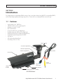
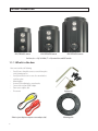
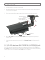
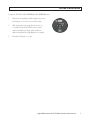
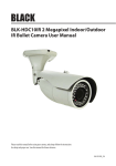
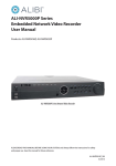
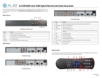
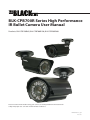
BLK-CPB700R Series High Performance IR Bullet Camera User Manual Products: BLK-CPB700R65, BLK-CPB700R150, BLK-CPB700R300 Please read this manual before using your camera, and always follow the instructions for safety and proper use. Save this manual for future reference. BLK-BulletCameras-2_CM 12/17/2013 ! WARNING CAUTION Changes or modifications not expressly approved by the manufacturer could void the user’s authority to operate the equipment. To prevent electric shock and risk of fire hazards, do NOT use other than the specified power source. REGULATORY NOTICE This device complies with Part 15 of the FCC Rules. Operation is subject to the following two conditions: (1) This device may not cause harmful interference, and (2) This device must accept any interference received, including interference that may cause undesired operation. This equipment has been tested and found to comply with the limits for a Class A digital device, pursuant to Part 15 of the FCC Rules. These limits are designed to provide reasonable protection against harmful interference in a residential installation. This equipment generates, uses, and can radiate radio frequency energy and, if not installed and use in accordance with the instructions, may cause harmful interference to radio communications. Operation of this equipment in a residential area is likely to cause interference, in which case the user will be required to correct the interference at his own expense. LEGAL NOTICE Observint Technologies (Observint) products are designed to meet safety and performance standards with the use of specific Observint authorized accessories. Observint disclaims liability associated with the use of non-Observint authorized accessories. The recording, transmission, or broadcast of any person’s voice without their consent or a court order is strictly prohibited by law. Observint makes no representations concerning the legality of certain product applications such as the making, transmission, or recording of video and/or audio signals of others without their knowledge and/or consent. We encourage you to check and comply with all applicable local, state, and federal laws and regulations before engaging in any form of surveillance or any transmission of radio frequencies. Other trademarks and trade names may be used in this document to refer to either the entities claiming the marks and names or their products. Observint disclaims any proprietary interest in trademarks and trade names other than its own. No part of this document may be reproduced or distributed in any form or by any means without the express written permission of Observint. © 2013 by Observint Technologies. All Rights Reserved. 11000 N. Mopac Expressway, Building 300, Austin, TX 78759 For Sales and Support, please contact your distributor. ii Table of Contents SECTION 1 SECTION 2 SECTION 3 SECTION 4 SECTION 5 APPENDIX A APPENDIX B Introduction . . . . . . . . . . . . . . . . . . . . . . . . . . . . . . . . . . . . . . . . . . . . . . . . . . . . . . . . . . . . . . . . . . . . . . . . 1 1.1Features. . . . . . . . . . . . . . . . . . . . . . . . . . . . . . . . . . . . . . . . . . . . . . . . . . . . . . . . . . . . . . . . . . . . . . . . . . . . 1 Installation . . . . . . . . . . . . . . . . . . . . . . . . . . . . . . . . . . . . . . . . . . . . . . . . . . . . . . . . . . . . . . . . . . . . . . . . . 4 2.1 General Guidelines. . . . . . . . . . . . . . . . . . . . . . . . . . . . . . . . . . . . . . . . . . . . . . . . . . . . . . . . . . . . . . . . . . . 4 2.2 Mounting the camera. . . . . . . . . . . . . . . . . . . . . . . . . . . . . . . . . . . . . . . . . . . . . . . . . . . . . . . . . . . . . . . . .4 2.3 Camera adjustments . . . . . . . . . . . . . . . . . . . . . . . . . . . . . . . . . . . . . . . . . . . . . . . . . . . . . . . . . . . . . . . . . 5 Software Setup. . . . . . . . . . . . . . . . . . . . . . . . . . . . . . . . . . . . . . . . . . . . . . . . . . . . . . . . . . . . . . . . . . . . . . 8 3.1LENS. . . . . . . . . . . . . . . . . . . . . . . . . . . . . . . . . . . . . . . . . . . . . . . . . . . . . . . . . . . . . . . . . . . . . . . . . . . . . . . 8 3.2EXPOSURE . . . . . . . . . . . . . . . . . . . . . . . . . . . . . . . . . . . . . . . . . . . . . . . . . . . . . . . . . . . . . . . . . . . . . . . . . . 9 3.3 WHITE BAL. . . . . . . . . . . . . . . . . . . . . . . . . . . . . . . . . . . . . . . . . . . . . . . . . . . . . . . . . . . . . . . . . . . . . . . . . 12 3.4DAY/NIGHT. . . . . . . . . . . . . . . . . . . . . . . . . . . . . . . . . . . . . . . . . . . . . . . . . . . . . . . . . . . . . . . . . . . . . . . . . 13 3.53DNR. . . . . . . . . . . . . . . . . . . . . . . . . . . . . . . . . . . . . . . . . . . . . . . . . . . . . . . . . . . . . . . . . . . . . . . . . . . . . .15 3.6SPECIAL . . . . . . . . . . . . . . . . . . . . . . . . . . . . . . . . . . . . . . . . . . . . . . . . . . . . . . . . . . . . . . . . . . . . . . . . . . . 16 3.7Adjust. . . . . . . . . . . . . . . . . . . . . . . . . . . . . . . . . . . . . . . . . . . . . . . . . . . . . . . . . . . . . . . . . . . . . . . . . . . . . 22 3.8RESET. . . . . . . . . . . . . . . . . . . . . . . . . . . . . . . . . . . . . . . . . . . . . . . . . . . . . . . . . . . . . . . . . . . . . . . . . . . . . 23 3.9EXIT. . . . . . . . . . . . . . . . . . . . . . . . . . . . . . . . . . . . . . . . . . . . . . . . . . . . . . . . . . . . . . . . . . . . . . . . . . . . . . . 23 Cleaning. . . . . . . . . . . . . . . . . . . . . . . . . . . . . . . . . . . . . . . . . . . . . . . . . . . . . . . . . . . . . . . . . . . . . . . . . . . 24 Specifications . . . . . . . . . . . . . . . . . . . . . . . . . . . . . . . . . . . . . . . . . . . . . . . . . . . . . . . . . . . . . . . . . . . . . . 25 Troubleshooting. . . . . . . . . . . . . . . . . . . . . . . . . . . . . . . . . . . . . . . . . . . . . . . . . . . . . . . . . . . . . . . . . . . . 27 Camera Dimensions. . . . . . . . . . . . . . . . . . . . . . . . . . . . . . . . . . . . . . . . . . . . . . . . . . . . . . . . . . . . . . . . . 28 BLK-CPB700R65 . . . . . . . . . . . . . . . . . . . . . . . . . . . . . . . . . . . . . . . . . . . . . . . . . . . . . . . . . . . . . . . . . . . . . . . . . 28 BLK-CPB700R150 . . . . . . . . . . . . . . . . . . . . . . . . . . . . . . . . . . . . . . . . . . . . . . . . . . . . . . . . . . . . . . . . . . . . . . . . 29 BLK-CPB700R300. . . . . . . . . . . . . . . . . . . . . . . . . . . . . . . . . . . . . . . . . . . . . . . . . . . . . . . . . . . . . . . . . . . . . . . . 30 High Performance IR CCTV Bullet Camera User Manual iii Precautions • • • • • • This camera should be installed by qualified personnel only. There are no user serviceable parts inside. Do not disassemble this camera other than to make initial adjustments. Use a UL approved regulated 24 volt AC or 12 volt DC power supply. Use appropriate low voltage power cable to prevent fire or electrical shock. Please insure that your installation area can support the weight of the camera. Handle this camera carefully • • • • • • • • • • • • • iv Do not use a strong or abrasive detergent when cleaning the camera. Do not install near cooling or heating devices. Do not install the camera in extreme temperature conditions. Use the camera in environments where temperature is within 14°F to 122°F. Use adequate ventilation if a camera is installed where high temperatures may occur. Do not install or use the camera in an environment where the humidity is high. Very high humidity levels can reduce image quality. Do not install the camera under unstable lighting conditions. Severe lighting change or flicker can cause the camera to work improperly. Do not touch the front lens of the camera. Be careful not to leave fingerprints on the lens cover. Do not drop the camera or subject it to physical shocks. Do not expose the camera to rain or spill liquids on it. If it gets wet, wipe dry immediately. Liquids can contain minerals that corrode the electronic components. Do not expose the camera to radioactivity. If exposed to radioactivity the CCD will fail. Do not disassemble the camera. There are no user-serviceable parts inside it. Do not drop the camera or subject them to physical shocks. It can cause malfunctions to occur. Never point the camera at a strong light, or exposing it to a spotlight or an object reflecting the strong light. Smear or blooming may occur, and it can damage the CCD. Before applying power to the camera, check the power source to ensure that it is within specifications. SECTION 1: INTRODUCTION SECTION 1 Introduction These high performance indoor/outdoor IR bullet cameras feature a very high resolution Sony® 960H CCD sensor providing 700 TVL, with True Day & Night capability, dual voltage range (24 Vac, 12 Vdc), and on-screen display (OSD) for control and setup. 1.1 Features • • • • • • • • • • • High resolution: color - 700 TV lines 3DNR (2D or 3D) for no noise or ghosting effect Maximum sens-up (x2 ~ x256) OSD control functions DC auto-iris varifocal lens, ×32 digital zoom Backlight compensation (BLC) and Day & Night mode Motion detection (4 zones) and privacy masking (8 zones) Digital Wide Dynamic Range function (D-WDR) Anti-fog lens IP67 rated and vandal proof hood Dual voltage (24 Vac or 12 Vdc) Cable channel Direction adjustment Elevation adjustment Horizon adjustment Drop cable Sun shield Power connector LENS, IR LEDs Video connector OSD Control Far-Near, Tele-Wide controls BLK-CPB700R camera High Performance IR CCTV Bullet Camera User Manual 1 SECTION 1: INTRODUCTION BLK-CPB700R65 camera BLK-CPB700R150 camera BLK-CPB700R300 camera Far-Near (∞ 1 N), Tele-Wide (T 1 N) controls lens and OSD controls 1.1.1 What’s in the box Your camera includes the following: • • • • • • • Four (4) coarse-threaded screws to secure the base plate to the mounting surface Four (4) machined screws to secure the camera bracket to the base plate Mounting plate Hex wrench for adjusting the camera bracket Camera video test port to BNC adapter Power source adapter cable This manual Video test port adapter and power source adapter (red) 2 Hardware kit Mounting plate SECTION 1: INTRODUCTION 1.1.2 Tools you need To install the camera, you will need: • • • • 12 Vdc or 24 Vac power source Tools for mounting the camera Video and power extension cables, if needed Hand-held CCTV video setup monitor (optional) High Performance IR CCTV Bullet Camera User Manual 3 SECTION 2: INSTALLATION SECTION 2 Installation 2.1 General Guidelines • Camera Lens: Handle the camera carefully to prevent scratching or soiling the lens. If the lens or IR array shield becomes soiled, clean it only with approved products. See the Cleaning section later in this manual. • Monitor impedance: Set the monitor impedance switch to 75Ω. • Power supply: To avoid fire or shock hazard, use only a UL listed power supply. • Camera drop cable: The camera drop cable includes two connectors: —— Power connector (red sleeve) – Use 24 Vac power source (AC24V 1A adapter) or 12 Vdc power source (DC12V 1A adapter). When applying 12 Vdc power, observe the power polarity. Power polarity indicators are molded onto the power connector sleeve (see the picture below). —— Video coax connector (BNC, yellow sleeve) – for transmission of the video signal across coax (75 Ω) cable. Power Polarity Indicators Power Connector Video BNC Connector 2.2 Mounting the camera The camera can be mounted on any surface with sufficient strength to support it. The video/power drop cable from the camera can be routed either through the cable hole in the center of the base plate, or through a cable guide in the mounting bracket. 1. Using the camera mounting plate as a guide, mark the location of the screws that anchor the mounting plate to the mounting surface. If you are routing the drop cable through base, also mark the position of the hole for the drop cable. NOTE 2. 4 Position the mounting plate so that the cable guide in the mounting bracket is pointing away from any source of water, dust, and other contaminates. Drill holes for the screws that anchor the base to the mounting plate to the surface. Four (4) course-threaded screws are provided. However, depending on the surface materials, more appropriate fasteners may be required. SECTION 2: INSTALLATION 3. Drill a 3/4” hole for the drop cable, if necessary. 4. Anchor the mounting plate to the mounting surface using the screws provided, or screws better suited for the surface structure. 5. Route the drop cable through the hole through the base plate, or through the cable guide in the mounting bracket, then attach the camera to the mounting plate using the four (4) machine screws provided. 6. Connect the camera drop cable to video and power cables as required. Drop cable connectors are not waterproof. NOTE 2.3 Camera adjustments In this procedure, set the camera to point at your surveillance target. Rotate the far - near and tele - wide rings to frame the video image. 1. Apply power to the camera. 2. Observe video from your camera on a monitor. a. If using a hand-held CCTV video setup monitor with your camera: i. Remove the cover to the OSD control panel by unscrewing it counter clockwise. BLK-CPB700R65 OSD Controls b. BLK-CPB700R150 and BLK-CPB700R300 OSD Controls ii. Connect the BNC adapter cable to the VIDEO TEST port on the OSD control panel. iii. Connect a CCTV setup monitor to the BNC adapter cable. If using a CCTV video system monitor to setup your camera, connect the video output of the camera to your CCTV monitor. High Performance IR CCTV Bullet Camera User Manual 5 SECTION 2: INSTALLATION 3. Verify that video from the camera can be seen on the monitor. 4. While observing video from the camera, loosen the direction adjustment lock nut and the elevation and horizon adjust hex screws (use the hex wrench provided). 5. Point the camera at your surveillance target, then tighten the lock nut and hex screws to hold the camera in place. Direction adjustment lock nut Elevation adjustment Horizon adjustment 360° 180° 360° OSD Control Far-Near, Tele-Wide controls 6. Rotate the Far - Near adjustment ring and the Tele - Wide adjustment ring to improve the image of the your surveillance target. 7. Configure your camera using the software menus in the OSD. See Software Setup in the following section of this manual. 2.3.1 LED LEVEL adjustment (BLK-CPB700R150, BLK-CPB700R300 only) The LED LEVEL is preset at the factory. However, an adjustment screw is provided on the OSD panel of the BLK-CPB700R150 and BLK-CPB700R300 cameras for environments where the image brightness in dark conditions is still not satisfactory after performing a Software Setup of the camera. The LED LEVEL of the BLK‑CPB700R65 camera is not adjustable. 6 SECTION 2: INSTALLATION To adjust the LED LEVEL of a BLK-CPB700R150 or BLK-CPB700R300 camera: 1. WIth the camera operating in a dark environment, unscrew the OSD panel access cover to access the OSD controls. 2. While observing the video image from the camera, use a screwdriver to turn the LED LEVEL screw to counterclockwise to brighten the image, and/or clockwise to darken the image until the image brightness is acceptable. 3. Reinstall the OSD panel access cover. High Performance IR CCTV Bullet Camera User Manual 7 SECTION 3: SOFTWARE SETUP SECTION 3 Software Setup The OSD SETUP menu can be viewed from the camera video output or through the VIDEO TEST port under the OSD Control cover. Configuration settings are made using the OSD control panel, located on the underside of the camera. Unscrew the cover to access the controls. Depending on the model of your camera, the OSD control panel may appear as one of the following: BLK-CPB700R65 OSD Controls BLK-CPB700R150 and BLK-CPB700R300 OSD Controls Use the SETUP joy stick on the OSD control panel to navigate through the menu system. Press the joy stick in (toward the camera) to enter the SETUP menu or select an entry, rock the stick up or down to highlight an item in the list, and left or right display the option you want to select. The SETUP menu consists of a list of sub-menus or displays the option selected for a camera function. When sub-menus are available, the symbol is shown. 3.1 LENS Highlight the LENS selection, press the joystick in (toward the control board) to open the DC LENS submenu. BRIGHTNESS: With the cursor pointing at the BRIGHTNESS option, rock the joystick left and right to change the setting. The DC Lens option provides 0 - 50 brightness adjustment steps. 8 SECTION 3: SOFTWARE SETUP MODE: Rock the joystick down to highlight MODE. Rock the joystick left or right do display INDOOR or OUTDOOR (installation environment). RETURN: To return to the SETUP menu and save your brightness and mode settings, rock the joystick down to highlight RETURN, then press it in to select return. 3.2 EXPOSURE To open the EXPOSURE submenu, highlight EXPOSURE, then press the joy stick in. The EXPOSURE sub-menu will open. SHUTTER: This function is used to select automatic (AUTO) shutter speed control, or set the shutter speed manually. SHUTTER speed can between 1/60 sec and 1/100,000 sec. AGC (AUTOMATIC GAIN CONTROL): Higher gain increases brightness but also increases any noise. When a high gain level is applied, higher noise levels are seen. OFF: AGC not active. AUTO: AGC level is determined by the camera. LOW: Sets gain to 28 dB. MIDDLE: Sets gain to 32 dB. HIGH: Sets gain to 36 dB. SENSE-UP: The SENSE-UP feature is used to sense the degree of darkness in low light or dark conditions and improve image brightness accordingly. OFF: SENSE-UP not active. AUTO: SENSE-UP is active. SENSE-UP level is determined by settings in the submenu. High Performance IR CCTV Bullet Camera User Manual 9 SECTION 3: SOFTWARE SETUP NOTE The SENSE-UP feature is only available when the SHUTTER option is set to AUTO or 1/60 (DC LENS). When SENSE-UP is activated, the increased magnification can induce noise and pixilation. SENSE-UP: Rock the joystick left or right to observe the optimal screen brightness in low light conditions. Select a multiplier between x2 ~ x256. RETURN: Highlight RETURN and press the joystick in to save changes and return to the EXPOSURE menu. BLC: Back Light Compensation. This feature enables the camera to compensate for strong back light conditions in a selected area of the image. OFF: The BLC function is disabled. BLC: The BLC function is enabled. Use the sub-menu to setup options. When selected, an area of the image where BLC is applied can be defined. GAIN: Select LOW, MIDDLE, or HIGH. The current selection is applied to the image. AREA: Select AREA to enter a graphical sub-menu for defining the position and size of the part of the image where BLC is applied. POSITION _ ^ SIZE ^ ^ 10 ^ ^ ^ _ SECTION 3: SOFTWARE SETUP —— —— —— After selecting the AREA graphical submenu, a POSITION screen opens. Rock the joystick up, down, left and/ or right to position the upper-left corner of the BLC area, then push the joystick in to confirm your selection and enter the SIZE graphical submenu. In the SIZE graphical submenu, rock the joystick up or down to raise or lower the bottom edge of the AREA. Rock the joystick left and/or right to contract or expand the AREA horizontally. Press the joystick in twice to return to the BLC menu. DEFAULT: Select DEFAULT to revert to the default AREA position and size. RETURN: Select RETURN to return to the EXPOSURE submenu. HSBLC (Highlight Suppression Back Light Compensation): The HSBLC feature enables you to suppress specific areas of the image that are very bright to improve the readability of darker areas. This feature is especially effective for reading car license plates at the night. HSBLC Off HSBLC On LEVEL: With the cursor pointing at LEVEL, rock the joystick right or left to increase or decrease the decrease the HSBLC level. MODE: Select either ALL DAY or --- (MODE off). DEFAULT: Select DEFAULT to revert to the default HSBLC settings. RETURN: Select RETURN to return to the EXPOSURE menu. High Performance IR CCTV Bullet Camera User Manual 11 SECTION 3: SOFTWARE SETUP D-WDR: The D-WDR feature employs intelligent light level control to compensate for strong backlight conditions. D-WDR Off D-WDR ON OFF: The D-WDR function is disabled. INDOOR: The D-WDR is preset with default LOW-LEVEL and HIGH-LEVEL settings for normal indoor lighting condition. These settings can be adjusted in the INDOOR sub-menu. RETURN: Select RET to return to the EXPOSURE menu. OUTDOOR: The D-WDR is preset with default LOW-LEVEL and HIGH-LEVEL settings for normal outdoor lighting condition. These settings can be adjusted in the OUTDOOR sub-menu. RETURN: Select RET to return to the EXPOSURE menu. RETURN: In the EXPOSURE menu, select RETURN to return to the SETUP menu. 3.3 WHITE BAL The WHITE BAL (white balance) function is used to control the screen color balance. ATW (Auto Tracking White Balance): Normal setting for a color temperature range from 1,800˚K to 10,500˚K (ex: a fluorescent lamp or outdoors). 12 SECTION 3: SOFTWARE SETUP AWB: The function to search for the color which is matched well with the ambient environment. AWC g SET: With this setting, focus the camera on white paper, then press the joystick in to set the white balance to ambient lighting conditions. If the environment and/or light source changes, the white balance should be re-adjusted. MANUAL: This option is used to make fine adjustments to the white balance setting. To use this option: —— —— Set the white balance using ATW or AWC. Select MANUAL. Rock the joystick right and/or left to Increase or decrease the value of BLUE (B-gain) or RED (R-gain) while monitoring the color of the image. —— NOTE Select RETURN to go to the SETUP menu. The White Balance may not be worked properly in the following conditions: * When there is a very high color temperature in the field of view, such as a clear sky or at sunset. * Extreme dark. * If the camera is aimed directly at fluorescent light, or if there is a drastic lighting change. If white balance adjustments don’t perform well, use AWB mode. 3.4 DAY/NIGHT The DAY/NIGHT feature is used to configure the camera to provide images in color, black and white, or either depending on lighting conditions. High Performance IR CCTV Bullet Camera User Manual 13 SECTION 3: SOFTWARE SETUP EXT: This feature is not used in these cameras. B/W: The picture is displayed in black and white only. When B/W is used, WHITE BAL is disabled. Selecting this option opens the B/W sub-menu. BURST: Burst ON sends a color signal to the monitor in B/W mode. This signal does degrade the clarity of the image from the camera. Some DVRs require a color burst signal to detect the camera. IR SMART: This option controls the IR LED output level to compensate for object distance. IR SMART is applied to objects in a specified area of the image. IR SMART off IR SMART on Selecting IR SMART ON opens the IR SMART sub-menu where you can set the IR gain and position and size of the target area. VALUE: With the cursor pointing to GAIN, rock the joystick right or left to increase or decrease the IR level. The default value is 50. AREA: Select AREA to enter a graphical sub-menu for defining the position and size of the part of the image where IR SMART is applied. —— 14 In the POSITION window, rock the joystick up, down, left and/or right to position the upper-left corner of the IR SMART area, then push the joystick in to confirm your selection and enter the SIZE graphical submenu. SECTION 3: SOFTWARE SETUP POSITION —— _ ^ SIZE _ ^ ^ —— ^ ^ ^ In the SIZE graphical submenu, rock the joystick up or down to raise or lower the bottom edge of the AREA. Rock the joystick left and/or right to contract or expand the AREA horizontally. Press the joystick in twice to return to the IR SMART menu. IR DWDR: Adjust this setting to the optimum value to produce the best dynamic range of the object in the area selected. The default value is 2. RETURN: Select RET to return to the B/W menu, or END to close the SETUP menu. COLOR: The picture is displayed in color. AUTO: In this mode, the camera automatically switches to COLOR in normal condition and to B/W mode when ambient illumination is low. Selecting this option opens the AUTO sub-menu. DELAY: This option specifies the switching time from color to B/W and B/W to color. The default setting is 5. D g N (AGC): This option sets the AGC brightness when switching from day to night. The default setting is 60. N g D (AGC): This option sets the AGC brightness when switching from night to day. The default setting is 20. RETURN: Select RET to return to the SETUP menu. 3.5 3DNR The 3DNR feature is used to reduce the level of background noise in a low luminance environment. OFF: Deactivates 3DNR noise reduction. High Performance IR CCTV Bullet Camera User Manual 15 SECTION 3: SOFTWARE SETUP ON: Activates the noise reduction feature. Selecting this option opens the 3DNR sub-menu where the level of noise reduction can be adjusted. LEVEL: With the cursor pointed at the LEVEL, rock the joystick left or right to decrease or increase the level of noise reduction. The default setting is 200 (maximum). RETURN: Select RET to return to the SETUP menu, or END to close the SETUP menu. 3.6 SPECIAL Selecting SPECIAL opens a feature list of special camera functions. CAM TITLE: This feature will display a user defined camera name on the image. OFF: When OFF is selected, the camera title is not displayed. ON: Selecting ON opens the CAMERA TITLE display where the title can be specified. If no label is selected, the title CAMERA 001 appears on the screen. 16 SECTION 3: SOFTWARE SETUP On the camera title screen: —— —— —— —— —— —— To enter a character in the title at the cursor position, rock the joystick up, down, left and right to highlight a character (0 - 9, A - Z, u - .). The character under the cursor and the bar under the character position title both blinks slowly. Press the joystick in to select the character and move to the next character position. To move to a character position in the title, highlight f or g (to move left or right), then press the joystick in. To erase a character position, move the cursor to the position using the f or g characters, then move the cursor to the position in the character array before the “0” (top line, leftmost position), and press the joystick in to select it (blank character. To clear all entries in the title, highlight CLR then press the joystick in. To position the title on the image, highlight POS, press the joystick in, rock the joystick up, down, left or right to move the title to the position you prefer, then press the joystick in to select it. To return to the SPECIAL sub-menu, highlight END, then press the joystick in. D-EFFECT: Allows you to apply a digital effect to the image, such as freezing the image, mirroring it, etc. FREEZE: When switched ON, this option temporarily maintains the current image on the screen. MIRROR: Rock the joystick left or right to select the mirror option you prefer. Mirror options include OFF, MIRROR, V-FLIP (vertical flip), and ROTATE (rotate 90° clockwise). High Performance IR CCTV Bullet Camera User Manual 17 SECTION 3: SOFTWARE SETUP MIRROR (off) MIRROR D-EFFECT selected D-ZOOM: D-ZOOM allows you to zoom in on a portion of the image by first setting the digital zoom magnification (x1 ~ x32), and then using the PAN and TILT controls to move to the area of the image you want to see. When D-ZOOM is used, SMART DZOOM and DIS are disabled. To use the D-ZOOM feature: —— Move the cursor to point at D-ZOOM, then rock the joystick right to set the RANGE (magnification). Similarly, adjust the PAN and TILT options to move to the portion of the image you want to magnify. —— RETURN: Select RETURN to return to the D-EFFECT menu. —— SMART DZOOM: Select this option to automatically magnify the a section area of image where motion is detected. The magnification level (RANGE), sensitivity, and the section of the screen to detect for motion are adjustable. When SMART ZOOM is used, D-DZOOM and DIS are disabled. 18 SECTION 3: SOFTWARE SETUP DIS (Digital Image Stabilizer): The DIS feature attempts to compensate for the ghosting in a low light conditions to produce a clearer image. DIS off DIS on NEG. IMAGE: Set this option to ON to show a color-reversed or black and white-reversed image. RETURN: On the D-EFFECT menu, select RETURN to return to the SPECIAL menu. MOTION: The MOTION feature allows you to quickly identify areas of the image where motion is detected. Set MOTION to ON then press the joystick in to open the MOTION sub-menu. You can configure up to four motion detect areas on the image. AREA: Move the cursor to AREA, then rock the joystick right or left to select 1, 2, 3, or 4. The area selected will blink in the background. AREA DISPLAY: Move the cursor to AREA DISPLAY, then rock the joystick right or left to select ON to configure that area, or OFF to disable that area. If ON, push the joystick in to open the submenu for the area selected: —— —— —— In the POSITION display, rock the joystick left, right, up and/or down to move the block (detection area) to the region of the display you want to monitor, then press the joystick in to select that position and move to the SIZE display. In the SIZE display, rock the joystick right or left to expand or contract the area horizontally. Rock the joystick down or up to expand or contract the area vertically. Press the joystick in twice to return to the MOTION submenu. Move the cursor to SENSITIVITY, then rock the joystick left or right to adjust the motion detection sensitivity for objects in you want the camera to detect in that area. Repeat this procedure to configure or disable the other motion detection zones. High Performance IR CCTV Bullet Camera User Manual 19 SECTION 3: SOFTWARE SETUP VALUE (sensitivity): VALUE allows you to select the camera sensitivity to movement in the area selected. The higher the setting value is, the higher the sensitivity to movement. MOTION VIEW: This feature is used to highlight objects found moving in motion detection areas. —— —— OFF. The feature is not used. ON: When motion is detected, the motion detection areas where motion is detected are highlighted. RETURN: Select RETURN to return to the SPECIAL menu. PRIVACY: The PRIVACY feature allows you to block up to 8 areas of the image from being seen. The areas blocked are covered by a color-coded polygonal (3-, 4-, or 5-sided) shape. Set PRIVACY to ON then press the joystick in to open the PRIVACY sub-menu. AREA: Set the cursor on AREA, then rock the joystick right or left to select any area 1 .. 8. These 8 areas can be individually enabled or disabled, positioned anywhere over image, are color coded, and can be reshaped. To setup a privacy for the area selected: —— —— —— Set the cursor on AREA DISPLAY and rock the cursor to ON to use the area, or OFF to disable it. If set to ON, press the joystick in to re-shape and position the privacy area: —— To reshape the privacy area, rock the joystick up, down, left or right to reposition the corner of the shape you want to move. Press the joystick in to move to another corner of the image, then advance to the POSITION display. You can reposition the top left, top right, bottom left, and bottom right corners of the shape. —— In the POSITION display, rock the joystick up, down, left or right to move the shape to the area you want to block, then press the joystick in to select it. If using the area, move the cursor to COLOR, and rock the joystick left or right to select one of 15 colors for the rectangle. Repeat this procedure for each of the 8 areas. RETURN: Select RETURN to return to the SPECIAL menu. DEFECT: This feature is used to eliminate up to 512 white spots (defects) in the image. Selecting DEFECT opens the DEFECT sub-menu. 20 SECTION 3: SOFTWARE SETUP SENSE-UP: Use this option to set the sensitivity for finding defects. The higher the value of “SENS UP”, the more defects will be compensated. Setting this level to x64 or x32 produces the best results. DIFF: Use this option to set the defect size from 1 to 3. The higher the DIFF value, the brighter the defects it will detect. Lower DIFF values detect fainter defects. THRESHOLD: The higher value of “THRESHOLD” you set, the more defects will be compensated. START: Selecting START initiates defect repair processing. Follow the instructions on the image to complete the operation RETURN: Select RETURN to return to the SPECIAL menu. DEFOG: The DEFOG function improves object recognition in foggy or dusty weather condition. DEFOG off DEFOG on OFF: Select OFF to disable this feature. AUTO: Press the joystick in to open the DEFOG AUTO submenu. In the submenu, set the DETECT LEVEL for the clearest picture. MANUAL: Select MANUAL to then press the joystick in to open the DEFOG MANUAL submenu: —— —— —— LEVEL: Rock the joystick left or right to select the level of the DEFOG function (0 .. 31). High level numbers apply more filtering. COLOR GAIN: Sets the color level (1 - 10). The higher the number, the more intense the color. EDGE GAIN: Sets the edge gain level (1 - 10). The higher the number, the more intense the color. GAMMA: Rock the joystick left or right to set adjust the camera for the best video appearance. High Performance IR CCTV Bullet Camera User Manual 21 SECTION 3: SOFTWARE SETUP —— —— GAMMA can be set to 0.05 to 1.00 in increments of 0.05, or set to USER (default). Select the GAMMA level to produce the best image on the monitor. NOTE: If you replace the monitor, you may need to change the GAMMA setting. RETURN: Select RETURN to return to the SPECIAL menu. RETURN: Select RETURN to return to the SPECIAL menu. 3.7 Adjust Use the adjust feature for perfecting the image from your camera. SHARPNESS: With the cursor pointing at SHARPNESS, rock the joystick right or left as necessary to produce the clearest image from your camera. MONITOR: Rock the joystick right or left to select the monitor type you using (LCD or CRT), or select USER. The monitor feature enables you to setup your camera to produce the best image for the monitor you use. Rock the joystick left or right to select either LCD, CRT or USER. In the monitor type sub-menu, adjust the settings for each parameter to produce the preferred image. RETURN: Rock the joystick to select RET, to return to the SETUP menu. 22 SECTION 3: SOFTWARE SETUP 3.8 RESET Use RESET to revert the camera configuration settings to the factory default values. FACTORY: Select FACTORY to reset the camera configuration. RETURN: Rock the joystick to select RETURN, to return to the SETUP menu. 3.9 EXIT Select EXIT to close the SETUP menu. High Performance IR CCTV Bullet Camera User Manual 23 SECTION 4: CLEANING SECTION 4 Cleaning Clean the camera dome with an approved glass cleaning solution and a lint free cloth. • • Dust can be removed from the unit by wiping it with a soft damp cloth. To remove stains, gently rub the surface with a soft cloth moistened with a mild detergent solution, then rinse and dry it with a soft cloth. Remove all foreign particles, such as plastic or rubber materials, attached to the camera housing. These may cause damage to the surface over time. CAUTION 24 Do not use benzene, thinner or other chemical products on the camera assembly; these may dissolve the paint and promote damage of the surfaces. Before using any chemical product, read the accompanying instructions carefully. SECTION 5: SPECIFICATIONS SECTION 5 Specifications Table 1.Component specifications Component BLK-CPB700R65 Sensor type BLK-CPB700R150 BLK-CPB700R300 1/3” Sony 960H CCD Effective pixels 976 (H) × 494 (V) approx. 480K pixels Total pixels 1020 (H) × 508 (V) approx. 520K pixels Resolution 700 TV lines Scanning system 2:1 Interlace Minimum illumination 0 lux (IR LED on) Video output 1.0 Vp-p composite. 75 Ohms S/N ratio 52 dB AGC Low / Middle / High Sens-UP OFF / AUTO (X2 ~ X256) Backlight compensation OFF / BLC / HLC D-WDR OFF / INDOOR / OUTDOOR Motion detection 4 zones Privacy masking 8 zones DIS (Digital Image Stabilizer) OFF / ON Communication Coaxial I/F (UTC) Day & Night Auto (AGC) / Day / Night / Ext White balance ATW / AWB / AWC->SET / Manual (1,800 K ~ 11,000 K) 3DNR (2D or 3D) 1 ~ 200 levels selectable Mirror H-Rev / V-Rev / ROTATE / PIP D-ZOOM x32 SMART DZOOM OFF / ON DEFOG OFF / MANUAL / AUTO Blemish compensation Auto (512 point) Power source Dual voltage Power consumption IR LED on: 300 mA max. IR LED on: 600 mA max IR LED on: 1000 mA max Lens DC auto iris varifocal lens (2.8 mm ~ 12 mm) DC auto iris varifocal lens (2.8 mm ~ 12 mm) DC auto iris varifocal lens (5 mm ~ 50 mm) High Performance IR CCTV Bullet Camera User Manual 25 SECTION 5: SPECIFICATIONS Component BLK-CPB700R65 BLK-CPB700R150 BLK-CPB700R300 Storage temperature, humidity -4 ºF ~ 140 ºF (-20 ºC ~ +60 ºC), humidity: 20 % RH ~ 95 % RH Operating temperature, humidity 14 ºF ~ 122 ºF (-10 ºC ~ +50 ºC), humidity : 20 % RH ~ 80 % RH Dimension (w × h × d) Weight 26 2.87 in × 3.19 in × 8.03 in (73 mm × 81 mm × 204 mm) 3.31 in × 3.50 in × 8.98 in (84 mm × 89 mm × 228 mm) 3.94 in × 5.28 in × 11.42 in (100 mm × 134 mm × 290 mm) 1.76 lb (800 g) 3.31 lb (1500 g) 4.41 lb (2000 g) APPENDIX A: TROUBLESHOOTING APPENDIX A Troubleshooting Problem Possible Cause Nothing appears on the screen - Check the power connection. - Check the video signal cable connection to the monitor. The video image is dim or not clear. - If the camera lens is dirty, clean it with a soft, clean cloth. - Adjust the monitor controls, if necessary. - If the camera is facing a very strong light, change the camera position.. - Adjust the lens focus. The screen is dark. - Adjust the contrast control of the monitor. - If you have an intermediate device, set the impedance (75Ω /Hi-Z) properly, and check the cable connections. The camera is not working properly and the surface of the camera is hot. - Verify that the camera is correctly connected to an appropriate regulated power source. The MOTION DETECTION function is not working - Is “MOTION DETECTION” mode turned on? - Check the setting of the MD AREA. The image on the monitor flickers - Make sure that the camera isn’t facing direct sunlight or fluorescent light. If necessary,change the camera position. Colors are not quite right. - Check the settings in the WHITE BAL menu. The SENS-UP does not work. - Verify that the AGC setting in the EXPOSURE menu isn’t set to OFF. - Check the SHUTTER setting in the EXPOSURE menu. High Performance IR CCTV Bullet Camera User Manual 27 APPENDIX B: CAMERA DIMENSIONS APPENDIX B Camera Dimensions BLK-CPB700R65 8.03” 180° 360° Side 2.87” 3.19” Front 28 360° APPENDIX B: CAMERA DIMENSIONS BLK-CPB700R150 8.98” 180° 360° 360° Side 3.31” 3.50” Front High Performance IR CCTV Bullet Camera User Manual 29 APPENDIX B: CAMERA DIMENSIONS BLK-CPB700R300 11.42” Side 7.41” 2.68” 360° 360° 6.30” 3.94” 3.82” 5.28” Front 3.46” 30 180°