1
Safe Operation
Practices • Set-Up • Operation
• Maintenance
• Service • Troubleshooting
• Warranty
L
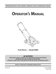
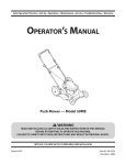
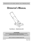
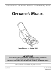
Rear Tine Tiller m Model Series 450
MTD LLC, P.O. BOX 361131 CLEVELAND, OHiO 44136-0019
PrintedIn USA
FormNo.769-05499
(October08, 2009)
1
ToTheOwner
ThankYou
Thank you for purchasing
a Garden Tiller manufactured
by
If you have any problems
MTD LLC. It was carefully engineered to provide excellent
performance
when properly operated and maintained.
Please read this entire manual
It instructs
prior to operating
your machine.
persons
who will operate
address and mailing
the equipment.
you how to safely and easily set up, operate
maintain
carefully
and
follow
concerning
address can be found
to ensure your complete
Please be sure that you, and any other
the machine,
or questions
the machine,
phone your local authorized MTD service dealer or contact us
directly. MTD's Customer Support telephone
numbers, website
Throughout
the
machine
satisfaction
this manual,
are observed
on this page. We want
at all times.
all references
to right and left side of the
from the operating
position
recommended
safety practices at all times. Failure to do so could
result in personal injury or property damage.
All information
product
in this manual
information
is relative to the most recent
available
at the time of printing.
Review
this manual frequently to familiarize yourself with the machine,
its features and operation.
Please be aware that this Operator's
Manual may cover a range of product specifications
for various
models. Characteristics
and features discussed and/or illustrated
in this manual
may not be applicable
to all models.
MTD LLC
reserves the right to change product specifications,
designs and
equipment
without notice and without
incurring obligation.
Table of Contents
Safe Operation
Practices ........................................
3
Engine Maintenance
..............................................
Service ....................................................................
16
20
Troubleshooting
.....................................................
21
Parts ................................................
22
Assembly & Set-Up ..................................................
Controls & Features ................................................
7
11
Operation
12
Replacement
14
Warranty
................................................................
Maintenance
&Adjustment.
.................................
RecordProductinformation
Before setting
up and operating
down
plate by standing
your new equipment,
[3N[3N[3N[3N[3ND
please
at the operator's
position
and looking
SERIALNUMBER
at the front right corner of the tine shield. This information
will be necessary, should
site, Customer Support
service dealer.
you seek technical
Department,
Back Cover
MODEL NUMBER
locate the model plate on the equipment
and record the
information
in the provided area to the right. You can locate the
model
..................................................
support
via our web
FINFINFINFINFIND
or with a local authorized
CustomerSupport
Please
do NOT return
If you have difficulty
this machine,
the machine
assembling
to the retailer
this product
you can seek help from
Visit us on the web at www.mtdproducts.com
0
Call a Customer
0
Write
Support
Representative
without
or have any questions
the experts.
0
or dealer
Choose
from
at (800) 800-7:310
us at MTD LLC • RO. Box :3611:31 • Cleveland,
first contacting
regarding
the options
the controls,
below:
or (330) 220-468:3
OH • 441:36-0019
our Customer
operation,
Support
Department.
or maintenance
of
2
importantSafeOperationPractices
WARNING!
This symbol
could endanger
all instructions
points
the personal
safety and/or
in this manual
with these instructions
out important
before
property
attempting
may result in personal
When you see this symbol.
safety instructions
of yourself
to operate
which,
if not followed,
and others.
this machine.
Read and follow
Failure to comply
injury.
HEED ITS WARNING!
CALIFORNIA
PROPOSITION
65
WARNING! Engine Exhaust, some of its constituents,
and certain vehicle components
contain or emit chemicals known to State of California to cause cancer and birth defects
or other reproductive
,A
WARNING!
Battery
compounds,
harm.
posts, terminals,
chemicals
known
and related
accessories
to the State of California
contain
lead and lead
to cause cancer and reproductive
harm. Wash hands after handling
DANGER! This machine
this manual.
operator
was built to be operated
As with any type of power
according
equipment,
carelessness
can result in serious injury. This machine
toes and feet. Failure to observe
the following
to the safe operation
is capable
practices
in
or error on the part of the
of amputating
safety instructions
fingers,
hands,
could result in serious
injury or death.
Training
1.
2.
Read, understand,
machine
all instructions
and in the manual(s) before
assemble
future
and follow
and operate.
and regular
attempting
Keep this manual
reference
on the
to
in a safe place for
and for ordering
replacement
3.
Be familiar with all controls and their proper operation.
Know how to stop the machine and disengage them
Never allow children under 14 years of age to operate this
machine. Children 14 and over should read and understand
the instructions
and safe operation
and on the machine
adult.
4_
5.
and be trained
small children
area.
in this manual
and supervised
by an
this machine
without
proper
clear of all persons, particularly
and pets. Stop machine
if anyone
enters the
Preparation
Thoroughly
Disengage
levers and shift (if provided)
clutch
starting
can be
this machine
in bare
into neutral
the engine.
Never leave this machine
unattended
with the engine
Never attempt
running,
to make any adjustments
except where specifically
operator's
while
engine is
recommended
in the
manual.
SafeHandling 0f 6as01ine:
in handling
injury
or property
gasoline. Gasoline
damage
is extremely
use extreme
flammable
care
and the
vapors are explosive. Serious personal injury can occur when
gasoline is spilled on yourself or your clothes which can ignite.
Wash your skin and change
clothes immediately.
a.
Use only an approved
b.
Never fill containers
gasoline container.
inside a vehicle
or on a truck
or trailer bed with a plastic liner. Always place
containers on the ground away from your vehicle
inspect the area where the equipment
is to
be used. Remove all stones, sticks, wire, and other foreign
objects
injury.
parts. Never operate
To avoid personal
Never allow adults to operate
instruction.
Keep the area of operation
practices
clothes or jewelry
caught in moving
feet or sandals.
running.
5.
quickly.
3.
4.
work shoes and close fitting
slacks and shirt. Loose fitting
('N") before
parts.
2.
Wear sturdy, rough-soled
which
could be tripped
over and cause personal
before filling.
When practical,
e_
equipment
11.
After striking
dispenser
nozzle.
12.
Keep the nozzle in contact
with the rim of the fuel
tank or container
at all times until fueling
opening
complete.
Do not use a nozzle lock-open
Extinguish
all cigarettes,
g.
Never remove
Disengage
is
handles).
device.
all clutch levers (if fitted)
Engine exhaust
indoors.
Never over fill fuel tank. Fill tank to no more than 1/2
of filler
15.
Use caution
when tilling
underground
utilities.
damage
i.
Replace gasoline
j.
If gasoline is spilled, wipe it off the engine and
equipment.
Move unit to another area. Wait 5
before starting
securely.
or fuel container
clothes
3.
4.
6.
while under
damage.
Keep bystanders
Repair any damage
the influence
caution
if anyone
when
Never operate
hard or slippery
the machine
Exercise caution
9.
Look down
Use only attachments
If situations
while
manual
2.
machine
towards
occur which
are not covered
Contact
proper
enters the area.
3.
by the
injury.
in this manual,
Customer
Support
use
for
dealer..
operating
at high transport
Do
speeds on
in safe
to cool at least five minutes
before
operation
with safety devices. Check their
regularly.
Check bolts and screws for proper tightness at frequent
intervals to keep the machine in safe working condition.
inspect
Before cleaning,
machine
repairing,
for any damage.
or inspecting,
stop the engine
and make certain the tines and all moving parts have
stopped. Disconnect the spark plug wire and ground it
on or crossing
hazards or traffic.
and accessories
Never tamper
Also, visually
4.
attachments
Allow a machine
against the engine to prevent
5.
Do not change
the engine.
the engine
The governor
unintended
governor
controls
starting.
settings
or over-speed
the maximum
safe
speed of engine.
or falling.
you.
6.
found
or replace
safety and instruction
labels, as
necessary.
7.
to the instructions
Maintain
in this
Follow this manual
transporting,
for safe loading,
unloading,
and storage of this machine.
and keep feet well away from the tines at all times.
Always refer to the operator's
if the machine
I
approved
order.
storing.
8.
4
and accessories
Failure to do so can result in personal
Keep machine,
working
it is in
and behind and use care when in reverse or
Start the engine according
while the engine is running.
assistance and the name of you nearest servicing
surfaces.
to avoid slipping
for
and operating.
20.
operating
8.
starting
Maintenance & Storage
of
of the handle bars and do not restrain the machine.
Exercise extreme
before
Never pick up or carry machine
parts. Contact with
away from the machine
Stop the machine
the spark plug wire
Inspect thoroughly
19.
Be careful when tilling in hard ground. The tines may catch
in the ground and propel the tiller forward. If this occurs,
pulling
the engine.
Keep all shields, guards, and safety devices in place and
operating properly.
not carry passengers.
10.
it against
disconnect
18.
1.
gravel surfaces. Stay alert for hidden
7.
start making
to till soil
hands and feet.
Never operate this machine without good visibility or light.
Always be sure of your footing and keep a firm hold on the
handles.
letgo
should
stop the engine,
care and good judgement.
operation.
5.
injury.
an unusual noise or
21.
Do not operate machine
alcohol or drugs.
and
If the machine
manufacturer.
Operation
2.
near fences, buildings
Rotating tines can cause property
17.
dryer or other gas appliances.
parts can amputate
hot and can cause a burn. Do
inside
is an open flame, spark or pilot light
as on a water heater, space heater, furnace,
the rotating
area.
an odorless
by attempting
vibration,
and remove any fuel soaked debris.
Do not put hands or feet near rotating
monoxide,
Do not overload machine capacity
too deep at too fast of a rate.
To reduce fire hazards, keep machine free of grass,
leaves, or other debris build-up. Clean up oil or fuel
where there
or
16.
the engine.
Never store the machine
stop
any adjustments,
or in a poorly ventilated
carbon
become
or personal
and ground
spillage
the
gas.
Muffler and engine
not touch.
fuel expansion.
minutes
indoors
contains
14.
neck to allow space for
cap and tighten
(behind
the engine
is hot or running. Allow engine to cool at least two
minutes before refueling.
inch below bottom
Repair
and stop engine
position
the tines, making
Never run an engine
and deadly
1.
disconnect
the engine.
Wait until the tines come to a complete
before unclogging
inspections.
cigars, pipes and other
gas cap or add fuel while
against
before you leave the operating
13.
Never fuel machine
I.
stop the engine,
Thoroughly
inspect the machine for any damage.
the damage before starting and operating.
fl
k.
object,
If this is not possible, then refuel such equipment
on
a trailer with a portable container, rather than from a
sources of ignition.
h.
a foreign
the spark plug wire and ground
gasoline
d_
remove gas-powered
from the truck or trailer and refuel it on the ground.
SECTION 2 --
IMPORTANT SAFE OPERATION
PRACTICES
manual
for important
is to be stored for an extended
period.
details
9.
If the fuel tank has to be drained,
10.
Observe
proper disposal
etc. to protect
11.
do this outdoors.
laws and regulations
the environment.
internal
According to the Consumer Products Safety Commission
(CPSC) and the U.S. Environmental
Protection Agency (EPA),
this product
SparkArrester
for gas, oil,
_
brushcovered
has an Average Useful Life of seven (7) years,
or 130 hours of operation.
Life have the machine
Atthe
inspected
combustion
engine and should
on ARNING!
or near anyThis
unimproved
machine
or grass-covered
land unless the
engine's
exhaust
system is equipped
end of the Average Useful
arrester
meeting
applicable
annually
any).
by an authorized
service dealer to ensure that all mechanical and safety
systems are working properly and not worn excessively.
Failure to do so can result in accidents,
injuries
or death.
Ira spark arrester is used, it should
working
order by the operator.
above is required
not be used
isforest-covered,
equipped with an
with a spark
local or state laws (if
be maintained
in effective
In the State of California
by law (Section
4442 of the California
the
Public
Notice Regarding Emissions
Resources Code). Other states may have similar laws. Federal laws
Engines which are certified to comply with California and federal
EPA emission regulations for SORE (Small Off Road Equipment)
A spark attester for the muffler is available through your
nearest engine authorized service dealer or contact the service
are certified
to operate
department,
may include
the following
Modification
(EM), Oxidizing
Injection
on regular
emission
unleaded
control
apply on federal
gasoline,
and
lands.
RO. Box 361131 Cleveland,
Ohio 44136-0019.
systems: Engine
Catalyst (OC), Secondary
Air
(SAI) and Three Way Catalyst (TWC) if so equipped.
SECTION 2 --
IMPORTANT SAFE OPERATION
PRACTICES
S
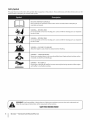
Safety Symbols
This page depicts and describes safety symbols that may appear
machine before attempting
to assemble and operate.
on this product.
Read, understand,
and follow
all instructions
on the
READ THE OPERATOR'S MANUAL(S)
Read, understand,
assemble
and follow
all instructions
WARNING--
WARNING--
WARNING--GASOLINE
parts. Contact with the rotating
parts can amputate
parts. Contact with the rotating
parts can amputate
IS FLAMMABLE
Allow the engine to cool at least two minutes
WARNING-monoxide,
area. Engine exhaust contains carbon
HOT SURFACE
and muffler
the muffler,
become extremely
the use of this power machine
I
SECTION 2 --
IMPORTANT SAFE OPERATION
operation.
Allow engine
to persons who read, understand
in this manual and on the machine.
SAVETHESEINSTRUCTIONS!
6
hot during
to cool before touching.
Your Responsibility--Restrict
and instructions
or in a poorly ventilated
an odorless and deadly gas.
Engine parts, especially
the warnings
before refueling.
CARBON MONOXIDE
Never run an engine indoors
WARNING--
follow
to
ROTATING TINES
Do not put hands or feet near rotating
hands and feet.
WARNING!
attempting
ROTATING TINES
Do not put hands or feet near rotating
hands and feet.
A
in the manual(s) before
and operate
PRACTICES
and
3
Assembly& Set-Up
Contents of Carton
OneTiller
One Depth
NOTE:This
Stake
operator's
The tiller illustrated
manual
Assembly
One Shift Rod
One Operator's
Manual
One Engine Operator's Manual
covers various models
may vary slightly
only those instructions
One Handlebar
which
of tillers.
from your machine.
pertain
to your model
number.
plug
wire and Before
groundassembly,
it against disconnect
the engine the
to spark
ARNING!
prevent unintended
starting.
_
Assembly
I.
Unpacking Instructions
to the right or left side of the tiller are
determined
behind
from
Tip the tiller forward
so that it rests on the front
counterweight.
NOTE: References
I.
Depth Stake
Follow
the machine
in the operating
position.
2.
Unthread
remove
Remove the staples, break the glue on the top flaps, or cut
the tape at the end of the carton and peel it along the top
the "T" knob from the top of the depth
Flat Washer
Remove any loose parts included
Operator's
with the tiller (i.e., the
Manual, etc.).
3.
Cut the corners and lay the carton down
4.
Remove the packing
5.
Roll or slide the tiller out of the carton.
thoroughly
6.
pin
from the clevis pin. See Fig. 3-I.
flap to open.
2.
stake and
the flat washer and hex bolt. Remove the cotter
flat.
material.
Check the carton
for loose parts.
Extend the control cable and lay it on the floor. Be careful
not to bend or kink the control cable.
NOTE:This
engine.
machine
is shipped
without
gasoline or oil in the
Be certain to service the engine with gasoline
as instructed
in the separate
Engine Operator's
Manual
and oil
before
Depth
operating.
Stake
Figure 3-1
3.
Raise the tine shield hinge flap assembly
depth
stake assembly
up through
4.
5.
the tine shield and depth stake
Secure it with the cotter
pin.
Insert the hex bolt into the top hole of the depth
assembly.
the T-knob
6.
the tine shield assembly.
Insert the clevis pin through
assemblies.
and insert the
in the slot, under the fine shield and
stake
Place the flat washer on the hex bolt and thread
onto the hex bolt. Tighten
Tip the tiller back down
securely. See Fig. 3-I.
so that it rests on the tines.
4.
HandlebarAssembly
1.
the clutch
Remove the top two bolts and flange lock nuts from the
handle mounting
brackets,
Remove the slot head screw, nut and two flat washers from
bail. See Fig. 3-4.
but do not remove the bottom
Head Screw
bolt and nut. See Fig. 3-2.
Washers
Bolts&Flange
/
Lock Nuts
/
/
/
!l_
Contro
Handle
/Handle
%_Bracket
Nut
Threaded
Tube
Figure 3=4
5.
Figure 3-2
2.
Place the handle assembly
mounting
3.
in position
between
6.
previously
removed.
ClutchCable
1.
Remove the threaded
and nut from the cable end.
2.
Route the clutch cable to the right side of the handle
mounting
brackets and underneath
the handle.
3.
Push the cable through
the hole in the center of the handle
and snap in the plastic fitting.
See Fig. 3-3.
Internally
Threaded
Tube
Figure
8
I
SECTION3--
Thread the eyebolt
ASSEMBLY&
3=3
SET-UP
it
and nut removed
earlier into the
internally threaded tube at the end of the cable. The thread
engagement
should be about 3/4".Tighten the nut against
the tube at the end of the cable. See Fig. 3-4.
NOTE: Do not overtighten
eyebolt
onto the bail by securing
the handle
brackets.
and secure with the hardware
eyebolt
from the top with the slot head screw, flat washers and lock
nut.
Line up the holes in the handle with the holes in the
bracket
Fasten the threaded
tension
the clutch cable. Too much
may cause it to break.
WARNING!
adjustment
Be certain to check the clutch cable
before operating the tiller.
ControlRod
Adjustments
1.
Make sure the handle assembly is in the highest
Refer to the Controls & Features Section.
2.
Remove the hairpin clips from
rubber washers in place.
3.
the control
position.
ClutchCable
NOTE: Service the engine
rod, put the
this adjustment.
removed
1.
hairpin clip. See Fig. 3-5.
Position
the tiller so the front counterweight
solid object,
2.
Rubber
checking
3.
With the gear selection
Rod
Standing
Bracket
4.
Manual.
on the right side of the tiller, examine
WARNING!
cover.
__
a
lever in NEUTRAL, start the engine.
(inside the belt cover). It should
Washer_
is against
such as a wall.
Refer to the separate Engine Operator's
ontrol
before
Manual packed with your tiller for proper fuel and engine oil
recommendations.
Insert the shorter, angled end of the control rod through
the indicator bracket on the shift cover and secure it with
the previously
with oil and gasoline
Refer to the separate Engine Operator's
Do not put your fingers
If the belt turns without
unthreading
the bail engaged,
the internally
the belt
not be turning.
threaded
under the belt
adjust it by
tube at the end of
the cable a few turns clockwise -- when standing in the
operator's position --and
then retighten the nut against
the tube.
k_
5.
Now move the shift lever to the FORWARD position.
6.
Carefully engage the clutch by lifting the clutch
against the handle. The wheels should spin.
7.
If the wheels
j
Figure
do not spin with the tiller in forward,
by unthreading
counter-clockwise
3-5
Insert the longer end of the control
the gear selector
rod through
bail
adjust
the tube at the end of the cable a few turns
-- when
-- and then retighten
4.
control
standing
in operator's
position
the nut against the tube.
the hole in
handle and secure with a cotter pin.
8.
Recheck both adjustments,
and readjust
as necessary.
NOTE:A secondary cable adjustment
is available if you reach
the point that additional adjustment
is needed. Remove the
belt cover and move the hex nuts at the other end of the cable
towards
handle.
the end of the casing. Then readjust
SECTION
3 --
the hex nuts at the
ASSEMBLY& SET-UP
9
Set-Up
Tires
The tires on your tiller may be over-inflated
purposes.
Reduce the tire pressure before
for shipping
operating
the tiller.
Recommended
operating tire pressure is approximately
p.s.i. (check the sidewall of the tire for the manufacturer's
recommended
20
pressure).
circumstances
is 30 p.s.i. tire
Equal
tire pressure
should
ARNING!
Maximum
pressure
under any
be maintained on both tires.
_
__
Gas& 0il Fill-Up
Service the engine
separate engine
instructions
with gasoline and oil as instructed
manual
in the
packed with your tiller. Read the
carefully.
WARNING!
Use extreme
care when
handling
gasoline. Gasoline is extremely flammable
and the
vapors are explosive. Never fuel the machine
indoors
SECTION
3--
or while
ASSEMBLY&
the engine
SET-UP
is hot or running.
4
Controls
and Features
Handle
Adjustment
Lock
r
Clutch Control
Depth Stake
Figure 4=1
EngineControls
See the separate
information
ChokeLever(if equipped)
Engine Operator's
and functions
Manual
The choke lever is used to enrich the fuel mixture
for additional
of the engine controls.
carburetor
GearSelection Handle
The gear selection
handle is located
when starting
Primer(If equipped)
on the front of the handle
The primer
is used when starting
assembly. It is used to select NEUTRAL, REVERSE, or one of the
FORWARD modes.
HandleAdjustmentLock
ClutchControl
The handle may be adjusted
the Handle Adjustment
The clutch control is located beneath the handle. Squeezing the
clutch handle against the handle engages the wheel and tine
drive mechanisms.
the desired
Lock.
position
a cold engine.
to the height
desired
Lock, then moving
and then re-locking
the Handle Adjustment
Make sure the valve is in the ON (horizontal)
control
by unlocking
the handle bars to
FuelShut-OffValve (if equipped)
ThrottleControl
The throttle
in the
a cold engine.
lever is located
on the engine.
engine speed and stops the engine.
It controls
the
position
when
starting
the engine.
Any time the tiller is not in operation
storing,
performing
maintenance
valve is in the OFF (vertical)
or adjustment),
(i.e.,
make sure the
position.
Depth Stake
The depth
stake controls
the tilling
depth.
11
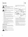
Operation
When using the tiller for the first time, use the second
Starting the Engine
adjustment
hole from the top (1" of tilling
depth).
See
Figure 5-1.
_
instructions and
warnings
on theand
machine
in
WARNING!
Read,
understand,
follow and
all the
this manual before operating.
NOTE:When pushing the machine with the engine off, you will
hear a ratcheting-gear sound coming from the tiller's chain case.
This is normal.
Use this position
for the first
of the tiller while
the that
engine
running
or being
WARNING!
Be sure
no is
one
is standing
in front
started.
1.
Place the gear selection lever in NEUTRAL.
2.
Place the throttle control lever in the FASTposition or-- if
equipped -- place the engine speed control in the START
position.
3.
Move the choke lever to the CHOKEposition or-- if
equipped -- push the primer two (2) or three (3) times.
Wait about two (2) seconds between each push.
)ort Position
Clevis
NOTE:A warm engine may not require choking or priming.
4.
Stand at the side of the tiller. Grasp the starter handle and
pull out slowly, until it pulls slightly harder. Let the rope
recoil slowly.
5.
Pull the starter handle rapidly. Do not allow the handle to
snap back. Allow it to recoil slowly while keeping a firm
hold on the starter handle.
6.
Repeat the previous
7.
steps until the engine starts.
As the engine warms up and begins to operate evenly,
move the choke lever gradually to the RUN position. If the
engine falters, return to the choke position,
Figure£1
2.
When breaking up sod and for shallow cultivation, use the
setting which gives 1" of tilling depth (second hole from
the top). Place the side shields in their lowest position.
3.
For further depth, raise the depth stake and side shields
and also make one or two more passesover the area.
4.
When tilling loose soil, the depth stake may be raised to its
highest position (use the bottom adjustment hole) to give
the deepest tilling depth. Raisethe side shields to their
highest position.
5.
To transport the tiller, lower the depth stake by using the
top adjustment hole.
6.
To adjust the depth stake, remove the clevis pin and hairpin
clip. Move the depth stake to the desired setting and
secure with the clevis pin and hairpin clip. See Figure 5-1.
then slowly
move to the RUN position.
NOTE:See the Engine Operator's Manual
tiller for more detailed instructions.
packed with your
Stopping the Engine
To stop the engine, move the throttle control to the STOPor
OFF position. Disconnect the spark plug wire and ground it to
prevent accidental starting while the equipment is unattended.
Setting the Depth
Tilling depth is controlled by the depth stake which can be
adjusted to five different settings. Adjust the side shields as you
adjust the depth stake.
i_
and
ground itAlways
againstdisconnect
the enginethe
before
WARNING!
sparkperforming
plug wire
any adjustments.
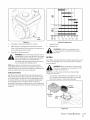
To adjust the side shields, remove the wing nuts. Move the
side shield to the desired
nuts. Tighten
position
and replace the wing
securely. See Fig. 5-2.
F
Operatingthe Tiller
1.
Select the depth
stake setting.
2.
Start the engine as instructed
Manual.
3.
Move the gear selection
modes or reverse.
WARNING!
in the Engine Operator's
handle to one of the forward
Do not move the gear selection
with the wheels or tines engaged.
;hields
handle
Make certain the
tiller is stopped completely
before changing the
gear selection. A partial engagement
may be
necessary
when engaging
the tines.
NOTE: Use the reverse tine drive when tilling virgin
ground, sod or hard soil. Use the forward tine drive when
cultivating
4.
or tilling
soft ground.
Squeeze the clutch handle against the handle to engage
the wheels and tines.
NOTE: Make certain the gear selection
indicator
positioned
before engaging the clutch handle.
between gears, the engine will stall.
k.
5.
For further
depth, raise the depth
stake and side shields
and also make one or two more passes over the area.
_hk
9.
When tilling
loose soil, the depth
stake may be raised to its
highest position by using the bottom adjustment
hole to
give the deepest tilling depth. Raise the side shields to the
highest
10.
position.
To transport
the tiller, do not engage the tines. Select the
wheel drive only.
Figure 5-2
8.
To transport
is correctly
If it is
that the wheels are lifted off the ground while using
WARNING!
the
tine drive, Do
or not
the push
tiller could
down move
on the backward
handles so
and
cause personal
6.
injury.
For best results, it is recommended
the garden
twice (lengthwise,
the soil.
to thoroughly
then widthwise)
be tilled
pulverize
the tiller, lower the depth stake by using the
top adjustment
hole.
SECTION
S --
OPERATION
13
6
Maintenance
& Adjustments
Lubrication
ground
it against
the engine
before plug
performing
ARNING!
Disconnect
the spark
wire and any
maintenance
or repairs.
_
Transmission
The transmission
Maintenance
requires
is pre-lubricated
no checking
and sealed at the factory.
unless the transmission
It
is disassembled.
To
fill with grease, lay the right half of the transmission
on its side,
add 22 ounces of Benalene 920 grease, and assemble the left
Engine
Refer to the separate Engine Operator's
maintenance
instructions.
Manual
half to it. This grease can be obtained
for engine
dealer by ordering
Support
Tires
number
part number
at your nearest authorized
737-0300
or calling
the Customer
on page 2.
Clutch Handle
Recommended
operating
tire pressure is approximately
14 p.s.i.
on 14 inch tires and 20 p.s.i, on 16 inch tires. (Check the sidewall
of the tire for the manufacturer's
recommended
pressure).
Maximum tire pressure under any circumstances is 30 p.s.i. Equal
tire pressure should be maintained
on both tires.
WARNING!
seating
Excessive pressure (over 30 p.s.i.) when
beads may cause the tire/rim
burst with force sufficient
assembly
to
to cause serious injury.
Air Cleaner
Lubricate
the pivot point
on the clutch handle and the cable at
least once a season with light oil. The control
in both directions.
Clean it every hour under extremely
normal conditions.
dusty conditions.
Poor
engine performance
or flooding usually indicates that the air
cleaner should be serviced. Refer to the Engine Operator's
Manual for maintenance
instructions.
SparkPlug
freely
PivotPoints
Lubricate
all the pivot points and linkages
at least once a season
with light oil.
TineShafts
Remove the tine assemblies
Service the air cleaner every 10 hours under
must operate
and lubricate
the tine shafts at least
once a season.
Wheel Shafts
Remove the wheel assemblies
least once a season.
and lubricate
the axle shafts at
Adjustments
The spark plug should be cleaned and the gap reset every
25 hours of engine operation.
Spark plug replacement
is
recommended
at the start of each tiller season; check the
Engine Operator's
specification.
Manual
for the correct
adjustments
while the engine is running, except
WARNING!
Never attempt to make any
where specified in the Operator's Manual.
plug type and gap
Engine Adjustment
Refer to the separate
adjustment
Engine Operator's
Manual
for engine
instructions.
HandleAdjustment
The handle may be adjusted to the desired
Controls & Features Section for details.
height.
Refer to the
Belt TensionAdjustment
Periodic adjustment
normal
of the belt tension
may be required
stretch and wear on the belt. Adjustment
tines or wheels
maintains
seem to hesitate while
turning,
if the
but the engine
the same speed. To adjust the tension
to the Assembly
due to
is needed
& Set-Up Section for instructions.
on the belt, refer
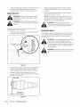
IdlerPulleyRod
After the belt tension
has been adjusted,
if the belt is excessively
stretched, you may need to adjust the idler pulley rod. This can
be checked easily.
With the engine offand
the gear selection
the clutch control
handle to each forward
bail disengaged,
bracket touches the idler pulley rod with the clutch control
disengaged, then an adjustment
is necessary.
1.
Disconnect
and ground
shift
mode. If the indicator
bail
the spark plug wire against the
engine.
2.
Remove the belt cover as described
Replacement
3.
under Belt
in the Service section.
Remove the hairpin
clip and spring washer from the idler
pulley rod. See Fig. 6-1.
ntrol Rod
Bracket
k.
Figure 6=1
4.
Move the idler pulley
bracket.
5.
Replace the spring washer and hairpin clip.
6.
Check the clearance
bracket
by shifting
rod to the lower hole in the idler
of the idler pulley rod to the indicator
to each forward
mode.
SECTION 6 --
MAINTENANCE
& ADJUSTMENTS
15
7
EngineMaintenance
MaintenanceSchedule
First S Hours
Each Useor
EverySeason
Every Season
EverySeason
Service
Every S Hrs.
or 25 Hours
or SOHours
orlO0 Hours
Dates
,/
CheckEngine Oil Level
Change Engine Oil
_"
_"
CheckAir Cleaner
_"
Service Air Cleaner
V/
CheckSparkPlug
V/
Replace Spark Plug
V/
Clean around muffler
V/
Periodic inspection and adjustment
of the engine is essential
if high level performance
is to be maintained.
Regular
Oil
maintenance
NOTE: Check the oil level before each use and after every five
hours of operation to be sure correct oil level is maintained.
will also ensure a long service life. The required
service intervals
and the kind of maintenance
to be performed
are described in the table above. Follow the hourly or calendar
intervals, whichever occur first. More frequent service is required
Check oil level regularly.
when operating
Seethe Assembly & Set-Up Section for instructions on how
to properly check the oil.
in adverse
conditions.
anyARNING!
maintenance.
prevent
accidental
Shut To
offthe
engine
before
disconnect the spark plug boot.
_L
start-up,
performing
NOTE: If engine must be tipped to transport equipment
inspect or remove grass, keep spark plug side of engine
Transporting
smoking,
cleaner.
or tipping
hard starting,
engine spark plug down
spark plug fouling,
Changingthe Oil
NOTE: Be sure to check engine on a level surface with the engine
or to
up.
may cause
or oil saturation
stopped.
Drain the oil while the engine
rapid and complete
I.
of air
Drain fuel from tank by running
engine until the fuel tank is
empty. Be sure fuel fill cap is secure.
2.
Remove drain plug and allow oil to drain into a suitable
container.
_
is still warm to assure
draining.
muffler
will be
hot. Behas
careful
to touchthe the
ARNING!
If very
the engine
been not
running,
muffler.
_li
See Fig. 6-I.
drain
oil, drainBefore
fuel from
tankengine
by running
engine
ARNING!
tipping
or equipment
until fuel tank is empty.
to
16
f
f
====l_
lOw
_
"%
_m_= _
m__
20w
20
mmm30
20w40, 20w50 _
I
_
_
_
v
15w40, 15w50 _____
®,
10w40 _Img
I
lOw30 _____n
_
_
("6)-30 o -20o -10° 0°
,,.
Drain
3.
Figure 6-1
Reinstall the drain plug and tighten it securely.
4.
Refill with the recommended
Refer to the Assembly
how to properly
5.
Reinstall
--
for instructions
2.
2-stroke
couldnon-detergent
shorten the engine's
AUTION!engine
DO oil.
NOTIt use
oil or
service life.
left in contact with the skin for prolonged
ARNING!
Used this
motor
oil may unless
cause skin
cancer if
periods.
Although
is unlikely
you handle
AirFilter
used oil on a daily basis, it is still advisable
Paper filters cannot
to
thoroughly
wash your hands with soap and water as
soon as possible after handling used oil.
compatible
with the environment.
sealed container
Temperature
Multi Viscosity
_
the oil fill cap securely.
oil in a manner
j
on
check the oil level.
NOTE: Please dispose of used motor
20o 300 40o
20o 40o 60o 80o 100°
Ambient
repeatedly
_
0°
10°
n/b.
r--
Single Viscosity
oil and check the oil level.
& Set-up section
(°F)-20 °
_
be cleaned
or every 100 operating
and must be replaced
once a year
hours; more often if used in extremely
dusty conditions.
that is
We suggest you take it in a
to your local service station
for reclamation.
Do
solvents for cleaning
WARNING!
Never
_i
or explosion
not throw it in the trash or pour it on the ground.
could
NOTE: Never run the engine
Oil Recommendations
the gasoline
air cleaner
element.
A fire
use
or low
flash point
result.
without
the air cleaner.
Rapid
engine wear will result.
SAE 10W-30 is recommended
for general, all temperature
When adding oil to the engine,
refer to the viscosity
use.
chart shown
on this page. Engine oil capacity is 600 ml (approximately
20 oz.).
Do not over-fill. Use a 4-stroke, or an equivalent high detergent,
premium
quality
automobile
SG, SF.Motor
container.
motor oil certified
manufacturer's
oils classified
1.
Press the tab on the air filter cover and lift the cover. See
Fig. 6-2. Replace paper element when dirty or damaged.
Clean foam element or replace when damaged.
to meet or exceed U.S.
requirements
for service classification
SG, SF will show this designation
on the
x
Air Filter
Cover
Figure 6-2
SECTION
7
--
ENGINE MAINTENANCE
17
2.
To clean foam element,
separate it from the paper element
and wash in liquid detergent
thoroughly
before
4.
and water. Allow to dry
Check that the spark plug washer is in good condition
and thread
using. Do not oil the foam element.
5.
After the spark plug is seated, tighten
wrench
WARNING!
plug removed.
the spark plug in by hand to prevent
to compress
NOTE:When
DO NOT check for spark with spark
installing
a new spark plug, tighten
spark plug seats to compress
If the engine
has been running,
tightened.
_
engine operation,
properly
and free of deposits.
1.
gapped
1/2turn
the washer.
the
muffler will be very hot. Be careful not to touch the
muffler.
To ensure proper
with a spark plug
the washer.
after the spark plug seats to compress the washer. When
reinstalling
a used spark plug, tighten 1/s-lAturn after the
DO NOT crank engine with spark
plug removed.
WARNING!
cross-
threading.
An improperly
tightened
spark plug can
plug damage
must bethe
securely
may
engine.
CAUTION!
become very The
hot spark
and
the spark plug must be
Cleaning the Engine
Remove the spark plug boot and use a spark plug wrench
If the engine
to remove the plug. See Fig. 6-3.
has been running,
an hour before
the engine.
compressed
cleaning.
Clean around
allow it to cool for at least half
Periodically
the muffler.
remove dirt build-up
from
Clean with a brush or
air.
CAUTION!
Do not spray engine with water to clean
because water could contaminate
fuel. Using a
garden
hose or pressure washing
also force water into the muffler
passes through
the muffler
equipment
opening.
can
Water that
can enter the cylinder,
causing damage.
WARNING!
Accumulation
of debris around
muffler
could cause a fire. Inspect and clean before every
use.
J
Figure 6-3
2.
Visually inspect the spark plug. Discard the spark plug if there
is apparent wear, or if the insulator is cracked or chipped.
Clean the spark plug with a wire brush if it is to be reused.
3.
Measure the plug gap with a feeler gauge. Correct as
necessary by bending side electrode.
should be set to 0.030 in.
Electrode
0.02-0.03 in.
4=--=== 0.60=0.80 rnrn
Figure 6-4
SECTION
7
--
ENGINE MAINTENANCE
See Fig. 6-4. The gap
Off-SeasonStorage
Engines stored between
30 and 90 days need to be treated
with
a gasoline stabilizer and engines stored over 90 days need to be
drained of fuel to prevent deterioration
and gum from forming
in fuel system or on essential
your engine deteriorates
the carburetor,
replaced.
1.
i_
carburetor
during
and other fuel system components,
Remove all fuel from tank by running
from lack of fuel.
is running.
WARNING!
Change the oil. See Changing
3.
Remove spark plug and pour about
into the cylinder.
distribute oil.
engine
Never leave engine
2.
4.
parts. If the gasoline
6.
until it stops
while
it
the Oil earlier in this section.
a 1/2ounce of engine
oil
the engine and the muffler.
Store in a clean, dry and well ventilated
that operates
areas that
area away from any
with a flame or pilot light, such
as a furnace, water heater, or clothes
dryer. Also avoid any
area with a spark producing
tools are operated.
motor, or where power
If possible,
also avoid storage
because that promotes
7.
or
Replace spark plug and crank it slowly to
Clean debris from around
appliance
serviced
unattended
Touch up any damaged paint, and coat other
may rust with a light film of oil.
5.
in
storage, you may need to have
Keep the engine
oil leakage.
electric
areas with high humidity,
rust and corrosion.
level in storage. Tilting
can cause fuel or
SECTION
7 -- ENGINEMAINTENANCE
19
7
Service
Belt Replacement
Fig. 7-1.
Your tiller has been engineered
with a belt designed for long
life and optimal performance.
It should never be replaced with
Off-SeasonStorage
a non-OEM
belt. Order all belts through
dealer or by contacting
2.
Customer
an authorized
Support
service
as instructed
on page
If the tiller will not be used for a period longer than 30 days, the
following
steps should be taken to prepare the tiller for storage.
Clean the exterior
Refer to Fig. 7-1 for the following
thoroughly.
Lubrication
steps.
of the engine and the entire tiller
Lubricate the tiller as described
instructions.
Using a pressure washer
to clean your tiller
in the
is not
recommended.
The washer may cause damage to the
electric components,
spindles, pulleys, bearings or the
engine.
Engine
PuJ
Using a pressure washers will result in shortened
life and reduce serviceability.
Refer to the Engine Operator's
engine storage instructions.
Manual for the correct
Wipe the tines with an oiled rag to prevent
rust.
Store the tiller in a clean, dry area. Do not store next to
corrosive materials, such as fertilizer.
Bolt
NOTE:When
unventilated
to rustproof
equipment
storing any type of power equipment
in an
area or metal storage shed, care should be taken
the equipment.
and especially
Using a light oil or silicone,
any springs, bearings,
coat the
and cables.
Figure 7-1
1.
Disconnect
and ground
the spark plug wire against the
engine.
2.
Remove the belt cover from the left side of the tiller by
removing the two hex head screws from the top of the belt
cover.
3.
Remove the two hex cap nuts and flat washers from the
front side of the belt cover. Remove the hex nut and flat
washer at the back of the cover.
4.
5.
Remove the belt keeper assembly located behind the
engine pulley by removing the two hex bolts and lock
washers.
Remove the old belt and install the new belt. Follow the
instructions
in reverse order to re-install
and belt cover.
NOTE: Upon reassembly,
the belt keeper
make certain the belt is routed
idler pulley and inside of belt keepers
by the engine
over the
pulley. See
2O
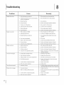
Troubleshooting
Problem
Engine fails to start
Engine runs erratic
Cause
Remedy
1. Fuel tank empty or stale fuel.
1. Fill tank with clean, fresh gasoline.
2. Throttle control lever not in correct starting
position (if equipped).
2. Move throttle
3. Blocked fuel line.
3. Clean fuel line.
4. Dirty air cleaner.
4, Refer to the Engine Operator's
5. Choke notin
5. Move switch to ON position.
ON position.
lever to start position.
Manual
6. Spark plug wire disconnected.
6. Connect wire to spark plug.
7. Faulty spark plug.
7. Clean, adjust gap or replace.
8. Engine flooded.
8. Refer to the Engine Operator's
1. Tiller running
1. Move choke lever to OFF position.
on CHOKE.
Manual
2. Spark plug wire loose.
2. Connect and tighten
spark plug wire.
3. Blocked fuel line or stale fuel.
3. Clean fuel line; fill tank with clean, fresh
gasoline.
4. Ventin
Engine overheats
5. Water or dirt in fuel system.
5. Drain fuel tank. Refill with fresh fuel.
6. Dirty air cleaner.
6. Refer to the Engine Operator's
Manual
7. Carburetor
7. Refer to the Engine Operator's
Manual
out of adjustment.
1. Engine oil level low.
1. Fill crankcase with proper oil.
2. Dirty air cleaner.
2. Refer to the Engine Operator's
Manual
3. Air flow restricted.
3. Refer to the Engine Operator's
Manual
4. Carburetor
Tines do not engage
4. Clear vent.
gas cap plugged.
not adjusted
1. Foreign object
properly.
lodged in tines.
4. Adjust carburetor as instructed
Operator's Manual
1. Dislodge foreign
2. Replace tine clevis ptn(s).
3. Pulley and idler not in correct adjustment.
3. Take tiller to authorized
4. Not shifting
4. Refer to the Operation
shifting
5. Control
cable not adjusted
6. Belt worn and/or
Tines skip over ground
object.
2. Tine clevis pin(s) missing.
properly.
1. Improper
properly.
stretched.
in the Engine
service dealer.
Section for proper
procedures.
5. Adjust control
cable
6. Replace belt.
rotation.
].
Forward
rotation
should only be used on soil
that has already been tilled, not on virgin soil.
Wheels do not engage
1. Replace clevis pin.
1. Clevis pin missing.
2. Tiller is not being shifted
properly.
2. Refer to Operation
Section for proper shifting
procedures.
3. Control
cable not adjusted
4. Belt worn and/or
stretched.
properly.
3. Adjust control
4. Replace belt.
cable
9
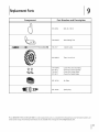
Replacement
Parts
Component
l
" -9
Phone (800) 800-7310
serial number
or (330) 220-4683
ready). Parts Manual
to order replacement
downloads
are also available
Part Number
and Description
954-0434
Belt, 4L x 58.16
742-0305A
Articulating
746-1117
Clutch Cable
Tine
934-04233
Tires, 14 x 4.5 x 6
714-04043
911-0415
714-0147
911-0415
Cotter
Clevis
Cotter
Clevis
951-10794
Air Filter
951-10292
Spark plug
parts or a complete
Pin, Tine Assembly
Pin, Tine Assembly
Pin, Depth Stake
Pin, Depth Stake
Parts Manual
(have your full model number
and
free of charge at www.mtdproducts.com.
22
1
MANUFACTURER'S
LiMiTED WARRANTY
The limited warranty set forth below is given by MTD LLC with
respect to new merchandise purchased and used in the United States
and/or its territories and possessions, and by MTD Products Limited
with respect to new merchandise purchased and used in Canadaand/
or its territories and possessions (either entity respectively, "MTD").
"MTD" warrants this product (excluding its Normal Wear Parts and
Attachments as described below) against defects in material and
workmanship for a period of two (2) years commencing on the date
of original purchase and will, at its option, repair or replace, free of
charge, any part found to be defective in materials or workmanship.
This limited warranty shall only apply if this product has been
operated and maintained in accordance with the Operator's Manual
furnished with the product, and has not been subject to misuse,
abuse, commercial use, neglect, accident, improper maintenance,
alteration, vandalism, theft, fire, water, or damage because of other
peril or natural disaster. Damage resulting from the installation or use
of any part, accessory or attachment not approved by MTD for use
with the product(s) covered by this manual will void your warranty as
to any resulting damage.
Normal Wear Parts are warranted to be free from defects in material
and workmanship for a period of thirty (30) days from the date of
purchase. Normal wear parts include, but are not limited to items
such as: batteries, belts, blades, blade adapters, tines, grass bags,
wheels, rider deck wheels, seats, snow thrower skid shoes, friction
wheels, shave plates, auger spiral rubber, engine oil, air filters, spark
plugs and tires.
Attachments-- MTD warrants attachments for this product against
defects in material and workmanship for a period of one (1) year,
commencing on the date of the attachment's original purchase or
lease. Attachments include, but are not limited to items such as:
grass collectors and mulch kits.
HOWTO OBTAINSERVICE:Warranty service is available, WITH
PROOFOF PURCHASE,through your local authorized service dealer.
To locate the dealer in your area:
In the U.S.A.
Check your Yellow Pages, or contact MTD LLC at RO. Box 361131,
Cleveland, Ohio 44136-0019, or call 1-800-800-7310, 1-330-2204683 or log on to our Web site at www.mtdproducts.com.
In Canada
Contact MTD Products Limited, Kitchener, ON N2G4J1, or call 1-800668-1238 or log on to our Web site at www.mtdcanada.com.
This limited warranty does not provide coverage in the following
cases:
a.
FOR
c. Service completed by someone other than an authorized service
dealer.
d. MTD does not extend any warranty for products sold or exported
outside of the United States and/or Canada, and their respective
possessions and territories, except those sold through MTD's
authorized channels of export distribution.
e. Replacement parts that are not genuine MTD parts.
f. Transportation charges and service calls.
g. MTD does not warrant this product for commercial use.
No implied warranty, including any implied warranty of
merchantability of fitness for a particular purpose, applies after
the applicable period of express written warranty above as to the
parts as identified. No other express warranty, whether written or
oral, except as mentioned above, given by any person or entity,
including a dealer or retailer, with respect to any product, shall
bind MTD. Duringthe period of the warranty, the exclusive remedy
is repair or replacement of the product as set forth above.
The provisions as set forth in this warranty provide the sole and
exclusive remedy arising from the sale. MTD shall not be liable
for incidental or consequential loss or damage including, without
limitation, expenses incurred for substitute or replacement lawn
care services or for rental expenses to temporarily replace a
warranted product.
Some states do not allow the exclusion or limitation of incidental
or consequential damages, or limitations on how long an implied
warranty lasts, so the above exclusions or limitations may not apply
to you.
In no event shall recovery of any kind be greater than the amount of
the purchase price of the product sold. Alteration of safety features of
the product shall void this warranty. You assume the risk and liability
for loss, damage, or injury to you and your property and/or to others
and their property arising out of the misuse or inability to use the
product.
This limited warranty shall not extend to anyone other than the
original purchaser or to the person for whom it was purchased as a
gift.
HOWSTATELAW RELATESTO THIS WARRANTY: This limited
warranty gives you specific legal rights, and you may also have other
rights which vary from state to state.
IMPORTANT: Owner must present Original Proof of Purchase to
obtain warranty coverage.
Log splitter pumps, valves, and cylinders havea separate oneyear warranty.
b. Routine maintenance items such as lubricants, filters, blade
sharpening, tune-ups, brake adjustments, clutch adjustments,
deck adjustments, and normal deterioration of the exterior finish
due to use or exposure.
MTD LLC, P.O. BOX 361131 CLEVELAND, OHIO 44136=0019; Phone: 1=800=800=7310, 1=330=220=4683
MTD Canada Limited = KITCHENER, ON N2G 4J1; Phone 1=800=668=1238
GDOC-100016 REV. B