1
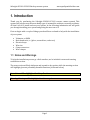
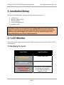
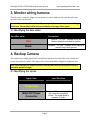
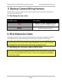
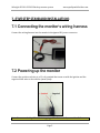
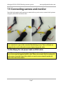
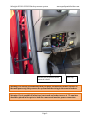
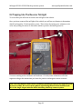
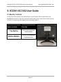
SAFESIGHT ™ SC0301-SC3102 Reverse back up camera system Installation Guide and User’s Manual Version 1 Table of Contents 1.Introduction...................................................................................................................................................................................................1 1.1Notesandwarnings ........................................................................................................................................................................1 2.Installation/Setup .......................................................................................................................................................................................2 2.1LCDmonitor .......................................................................................................................................................................................2 2.2Monitorinputs...................................................................................................................................................................................2 3.Monitorwiringharness ............................................................................................................................................................................3 3.1Identifyingthebarewires............................................................................................................................................................3 4.Backupcamera ............................................................................................................................................................................................3 4.1Identifyingcamerainputs ............................................................................................................................................................3 5.Backupcamerawiringharness............................................................................................................................................................4 5.1Identifyingthebarewires...........................................................................................................................................................4 6.RCAextensioncable ..................................................................................................................................................................................4 6.1IdentifyingtheredpowerleadsonRCAcable....................................................................................................................5 7.Fivestepstandardinstallation..............................................................................................................................................................5 7.1Connectingthemonitorswiringharness..............................................................................................................................5 7.2Poweringupthemonitor .............................................................................................................................................................5 7.3Connectingthecamera’swiringharness ..............................................................................................................................6 7.4Poweringupthecamera...............................................................................................................................................................6 7.5Connectingcameraandmonitor...............................................................................................................................................7 7.6IdentifyingtheredpowerleadsonRCAcable....................................................................................................................5 8.Tapingintoa+12voltterminal.............................................................................................................................................................8 8.1Mainpowerconnection.................................................................................................................................................................8 8.2Tappingintoareversetaillight .............................................................................................................................................10 9.SC0301‐SC3102userguide..................................................................................................................................................................11 9.1Monitorcontrols............................................................................................................................................................................11 10.Troubleshooting.....................................................................................................................................................................................12 10.1Monitorisconnectedto+12voltsbutwillnotturnon ............................................................................................12 10.2Thecamerasystemworksbuthasalotofstaticandlinesrunningthroughthepicture..........................12 10.3Monitorisdisplayingaverydimimage ...........................................................................................................................12 10.4Monitorrandomlyturnsonandoff ...................................................................................................................................13 10.5Bothcameraandmonitorareconnectedto+12voltsbutthereisstillnopicture......................................13 SafesightSC0301‐SC3102Backupcamerasystem www.qualitymobilevideo.com 1. Introduction Thank you for purchasing the Safesight SC0301‐SC3102 reverse camera system! This systemwillhelppreventthemostdeadlytypeofautomobileaccidents,reversingaccidents. Allthat’sleftistoinstallanduseyoursystem.Inthefollowinginformationwewillguide youthroughinstallingyoursystemandgettingthemostoutofit. Firstwebeginwithacoupleofthingsyoushouldhaveonhandtohelpwiththeinstallation ofyoursystem: VoltmeterorDMM Basichandtools,i.e.(pliers,screwdriver,socketset) Electricaltape Wireties Crimpconnectors Wirecrimper 1.1 Notes and Warnings Tohelptheinstallationprocessgoalittlesmother,we’veincludedanotesandwarning notificationsection. Thenotessectionwillhelpelaborateandexpandonkeypoints,whilethewarningsection willhighlight/preventpotentiallyharmfulsituations(asshownbelow). Note:Noteswillbehighlightedinthisyellowbox. Warning:Warningswillbehighlightedinthisorangebox. Page1 SafesightSC0301‐SC3102Backupcamerasystem www.qualitymobilevideo.com 2. Installation/Setup Webeginbyidentifyingthecontentsofthebackupcamerasystem: 1. LCDMonitor 2. Monitorwiringharness 3. Backupcamera 4. Camerawiringharness 5. Extensioncable Warning:Allelectricalconnectionsshouldbedoneafterremovingthenegativepost ofthebattery.Undernocircumstancedoesqualitymobilevideo.comassumeany liability.Usetheseinstructionsatyourownrisk.Theseinstructionsaremeantasa guidebutrequireknowledgebytheinstaller.Ifyouareunfamiliarpleaseseek professionaladvicepriortoanyandallinstallation. 2.1 LCD Monitor Themonitorhasasinglepigtailwiththreedifferentinputsattheendofthecord,ayellow, whiteandred. 2.2 Identifying the inputs Input Color Input Function Primary video input Yellow Input Secondary Video input White Input Red DC Power Connector This is the DC power connector; the center pin is positive 12volts. The outer shield is negative 12 volts. Page2 SafesightSC0301‐SC3102Backupcamerasystem www.qualitymobilevideo.com 3. Monitor wiring harness ThisDCpowerconnectorplugsintothemonitor’spowerinputononeend,andsplitsinto twobarewiresontheother Note:Intheeventthatthemonitorwillnotrespondpleasemakesureitisreceivinga videofeed.Thismonitorwillnotturnonwithoutreceivingavideosignal 3.1 Identifying the bare wires Bare Wire color Connection Red Positive + 12 volts – connect this to an electric terminal controlled by ignition Black Negative – 12 volts – connect this to vehicle’s (metal) body/ clean ground 4. Backup Camera The camerahasasinglepigtailwithtwodifferentinputsattheendofthecord,ablackfor powerandyellowforvideo.Thecameraalsocomeswithinfraredlightsfornighttimeuse. Note:Infraredlightsoncameraarenotvisiblebythenakedeyebutprovideablack andwhitepictureatnight. 4.1 Identifying the inputs Input Color Input Function Primary video input Yellow Input Black DC Power Connector This is the DC power connector; the center pin is positive 12volts. The outer shield is negative 12 volts. Page3 SafesightSC0301‐SC3102Backupcamerasystem www.qualitymobilevideo.com 5. Backup Camera Wiring Harness ThisDCpowerconnectorplugsintothecamera’spowerinputononeend,andsplitsinto twobarewiresontheother 5.1 Identifying the bare wires Bare Wire color Connection Red Positive + 12 volts – connect this to an electric terminal controlled by ignition Black Negative – 12 volts – connect this to vehicle’s (metal) body/ clean ground 6. RCA Extension Cable ThissingleyellowRCAvideocableisincludedwiththecameraandisdesignedtotakethe videosignalfromthecameraanddisplayitonthemonitor.(Usually18‐25ftlong) Note:TheyellowRCAcablemayhavetworedpowerwiresoneachend.Theydonot needtobeconnectedasapartofthestandardinstallationprocess.Theseredleads aredesignedtobeusedasalternativemeansofpoweringuptheunits. 6.1 Identifying the red power leads on RCA cable Note:Theseredleadsareadirectpassthroughwire.Itisasthoughyouhaveasingle pieceofwirerunthelengthoftheRCAcable.Thesewirescanbeusedtosendpower tothecamerafromthefrontofthevehicle,orsendareversesignalfromthelightto thefrontofthevehicle Page4 SafesightSC0301‐SC3102Backupcamerasystem www.qualitymobilevideo.com 7. (FIVE STEP STANDARD INSTALLATION) 7.1 Connecting the monitor’s wiring harness Connectthewiringharnessintothemonitor’sdesignatedDCpowerconnector. 7.2 Powering up the monitor Connectthepositiveredwiretoa12voltterminalthatturnsonwiththeignitionandthe negativeblackwiretothevehicles(metal)body. Note:Foramoreindepthlookintotappinga12voltterminal,seesection8.1 Page5 SafesightSC0301‐SC3102Backupcamerasystem www.qualitymobilevideo.com 7.3 Connecting the camera’s wiring harness Connectthewiringharnessintothecamera’sdesignatedDCpowerconnector. 7.4 Powering up the camera Connectthepositiveredwiretoa+12voltsideofthereverselightandthenegativeblackwiretothe vehicles(metal)body. Note:Tohavecontinuousoperation,connecttoapowersourcethatturnsonwith theignition.Foramoreindepthlookintotappinga12voltterminal,seesection8.1 Page6 SafesightSC0301‐SC3102Backupcamerasystem www.qualitymobilevideo.com 7.5 Connecting camera and monitor Nowthatbothmonitorandcameraareconnectedtoapowersource,connectbothsystems usingtheyellowRCAextensioncable. Note:IftheyellowRCAcablehastworedpowerwiresoneachend,theydonotneed tobeconnectedasapartofthestandardinstallationprocess.Theseredleadsare designedtobeusedasalternativemeansofpoweringuptheunits. 7.6 Identifying the red power leads on RCA cable Note:Theseredleadsareadirectpassthroughwire.Itisasthoughyouhaveasingle pieceofwirerunthelengthoftheRCAcable.Thesewirescanbeusedtosendpower tothecamerafromthefrontofthevehicle,orsendareversesignalfromthetail‐ lighttothefrontofthevehicle. Page7 SafesightSC0301‐SC3102Backupcamerasystem www.qualitymobilevideo.com 8. TAPPING INTO A POSITIVE + 12 VOLT TERMINAL 8.1 Main power connection Themainpowerconnectioncanbemademanydifferentways.Youcanconnectmain powerby: Usingacigarettelightercord Tapingthebackofacigarettelighter Tappingpoweratthefuseblock Tappingpowerfromanauxiliarycircuit Tappingpowerfromthekeycylinder Tappingdirectlyintothereversetail‐light Themethodwerecommendistoconnectpowertothefuseblock.Werecommendusinga voltmetertofindafuseorcircuitthatturnsonwiththekeyandisnotacriticalcircuitlike “ABSpump”.Youtypicallywanttotapcircuitslikeradio,cigarettelighter,auxiliarypower socket.Intheeventofashortcircuityouwillnotloseacriticalcomponentthatcould compromisesafety. Theeasiestwaytotapthefuseblockistopurchaseafusetapfromusoranymajorauto partsstore.Thefusetapwillsupplyyouwithaterminalorwireinwhichyouwillconnect toyourfuse. Atthefuseblockyoumakeyourpositivepowerconnectionforboththemonitorand camera. Thenegativepowerconnectioncanbemadeanywhereonthevehicle.Werecommendthat youplacethegroundonafactorygroundterminalorprepareanewonebygrindingaway thepainttoexposebaremetal. Page8 SafesightSC0301‐SC3102Backupcamerasystem www.qualitymobilevideo.com In‐linefusetoprotectinthe eventofashort Fusetap Warning:Itisalwaysrecommendedthatyouplaceaninlinefusewithin6inchesof themainpowertap;thisprotectsthesystemandthewiringintheeventofashort. Warning:Fireispossibleifinlinefuseisnotusedandashortoccurs.A7.5ampfuse shouldbeplacedinlinepriortoboththecameraandmonitorpowerconnection. Page9 SafesightSC0301‐SC3102Backupcamerasystem www.qualitymobilevideo.com 8.2 Tapping Into The Reverse Tail-light Toaccessthisyouwillneedtoremovethetaillightofthevehicle. Onceyouhaveremovedthetaillightofthevehicleyouwilluseavoltmetertodetermine whichleadsupplies12voltspositivepower.Thisisdonebysettingyourvoltmetertodc voltsandprobingthewirestodeterminewhichispositiveandwhatgroundis. Acorrectreadingonthevoltmeterwillindicate+12volts;somevoltmeterswillread negativevoltage,thismeansthatyouhavethepositiveandnegativewiresreversed. Note:Thisstepmustbedonewithavoltmeter;guessingorusingatestlightwillyield incorrectresults.Wereceivemanyphonecallsstatingdefectivemerchandiseand thisisthesinglelargestmistakewheninstallingabackupcamerasystem. Page10 SafesightSC0301‐SC3102Backupcamerasystem www.qualitymobilevideo.com 9. SC0301-SC3102 User Guide 9.1 Monitor Controls Onthefrontofthemonitoryouwillfindtherearenobuttons.Mostnotablythereisno on/offpowerbuttononthisunit,insteaditisbuiltwithanautosensefeaturethatturnson assoonasitsensesanyvideosignal,suchasabackupcamera. Button Location Function Top Button Controls the mirror/non mirror function Bottom Button Controls four designated brightness levels Page11 SafesightSC0301‐SC3102Backupcamerasystem www.qualitymobilevideo.com 10. Troubleshooting Thissectionoftheguideshouldhighlightcommonissuesusersmayencounterandoffer simplesolutions. 10.1 Monitor is connected to + 12 volts but will not turn on TheSC3102backupmonitordoesnothaveabluestandbyscreenwhennotreceivinga videofeed.Thismeansthatifthecameraisnotreceivingpowerandsendingavideosignal tothemonitor,itwillnotturnon. 1. Makesurethecamerahaspower. 2. MakesurethecameraisconnectedtothemonitorusingtheRCAextensioncable. 10.2 The camera system is working but has a lot of static and lines running through the picture Thisistypicallycausedbypoorgroundconnectionoratapped+12voltterminalthatis receivingalotofnoise. 1. Makesurethatyouhaveasolidgroundconnection.Ifnotsimplyfindabetter groundanditshouldsolvealargemajorityofstaticornoise. 2. Ensuretheterminaltappedinfor+12voltisnotreceivingalotofnoise. 3. Iftheproblemstillpersistsaftermakingsurethereisasolidground,we recommendtappingintoadifferent+12voltterminal. 4. Arelaymayberequiredonsomenewervehiclesduetothelightingsystemsthatare controlledbycontrolmodulesthatemitACvoltage. 10.3 Monitor is displaying a very dim picture Adimpictureonthemonitorismostoftencausedbysimplebrightnesslevelsettingson themonitororinsomecasesaweakpowerconnection. 1. Makesurethebrightnesslevelsettingsonthemonitorarenotsettolow. 2. Ifthebrightnesslevelsonthemonitoraresettolowadjustasdesired. 3. Ensurebothcameraandmonitorareproperlyconnectedtoastrong+12volt terminal. Page12 SafesightSC0301‐SC3102Backupcamerasystem www.qualitymobilevideo.com 10.4 Monitor randomly turns on and off Themonitorwillrandomlyturnonoroffiftheincorrectreversecircuitisused.Many newervehicleshavelightbulbsthathavedualfilaments.Dualfilamentbulbstypicallyhave athreewireconnection. 1. Useavoltmetertodeterminewhichwireisthecorrectonetotap. 2. Metermustread12voltswhenthevehicleisplacedintoreverse.Anyfluctuation involtagelargerthan1voltgenerallymeansthattheincorrectwirehasbeen tapped. 3. Tapthereversewireusinganinsulatedwiretap. 4. Thereverselightmaybecontrolledbyalightingmodule;inwhichcasearelay wouldbeneeded. 10.5 Both camera and monitor are connected +12 volts but there is still no picture SincetheSC3102monitorhasanauto‐sensefeature,ifthereisnopictureonthemonitorit couldbeduetoafaultyconnectiononthecameraendormonitorend. 1. Makesurethemonitoriscorrectlyconnectedtoa+12volts 2. Makesurethecameraisconnectedtoa+12volts 3. EnsuretheRCAextensioncableisconnectedcorrectlyonboththecameraand monitorend. 4. Testthemonitorusingadifferentvideosourcetodetermineifthemonitoris faulty 5. Testthecamerawithadifferentmonitortodetermineifthecameraisfaulty Page13