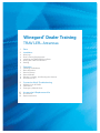
1
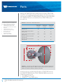
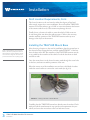
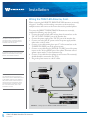
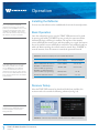
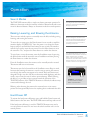
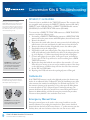
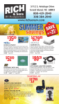
Winegard® Dealer Training
TRAV’LER® Antennas
1
Parts
2
Installation
7
Operation
9
Conversion Kits & Troubleshooting
2
2
3
4
6
7
7
7
8
8
8
9
9
9
10
10
10
Warnings
Roof Location Requirements
Installing the TRAV’LER Mount Base
Wiring the TRAV’LER Antenna
Sealing
Installing the Reflector
Basic Operation
Receiver Setup
Search Modes
Raising, Lowering, and Stowing the Antenna
Hard Power Off
RP-SK21/11 & OE-DISH
Calibrate EL
Emergency Manual Stow
Accessories & Replacement Kits
Accessories
Replacement Kits
Parts
Although all TRAV’LER multi-satellite antennas include a TRAV’LER
mount base and a satellite provider specific reflector, the dimensions vary in
size between the DIRECTV SWM TRAV’LER antenna, the DISH®/Bell
TV™ TRAV’LER antenna, and the Shaw Direct TRAV’LER antenna
(see table 2.1).
The following parts are included with
all models of TRAV’LER antennas:
• Installation/operation manual
• TRAV’LER mount base with
attached 30′ power/control cable
• Reflector
• TRAV’LER interface box
• Interface box power supply
• 24″ AC power cord
• 30′ coaxial cable
• Mounting hardware
• Cable entry hardware
TABLE 2.1. Dimensions of TRAV’LER antennas
DIRECTV SWM
TRAV’LER
antenna
DISH/Bell TV
TRAV’LER
antenna
Shaw Direct
TRAV’LER
antenna
Length of assembled antenna
(see fig. 2.1A)
44″
42″
46″
Width of antenna with reflector
(see fig. 2.1B)
34″
25″
37″
23.5″
23.5″
23.5″
Maximum width of mount base
(see fig. 2.1D)
24″
24″
24″
Minimum width of mount base
(see fig. 2.1E)
21″
21″
21″
Width of antenna without reflector
(see fig. 2.1C)
A
C
B
E
D
FIGURE 2.1. Dimensions of TRAV’LER antenna. A, Length of assembled antenna. B,
Width of antenna with reflector. C, Width of antenna without reflector. D, Maximum
width of mount base. E, Minimum width of mount base.
Aside from the parts included with all models of TRAV’LER antennas,
the DIRECTV SWM Slimline TRAV’LER (SK-SWM3) antenna also
includes the following parts:
1. 21V SWM power inserter
2. DIRECTV® 4-way SWM splitter
1
TRAV’LER Multi-Satellite TV Antennas
Parts
Installation
Warnings
Do not attempt to install this system in the rain or under any wet conditions.
Moisture may affect electronics and void your warranty.
Do not paint the antenna. Painting the antenna will void your warranty.
Pay attention to the pinch points as the antenna raises. The pinch points
should be labeled on the antenna.
Roof Location Requirements
Before installing the antenna, make sure that the chosen location meets the
minimum roof space requirements for the antenna (see table 2.2). Note that
the length of the antenna must be parallel to the centerline of the vehicle.
For best performance and to reduce
signal acquisition time, park the
vehicle on a level surface that is free of
obstructions such as trees or buildings.
TABLE 2.2. Roof space requirements for TRAV’LER antennas
Minimum area required (length x width)
DIRECTV SWM TRAV’LER antenna
44″ x 34″
DISH/Bell TV TRAV’LER antenna
42″ x 25″
Shaw Direct TRAV’LER antenna
46″ x 37″
Before removing the TRAV’LER
antenna from its box, contact your RV
dealer or manufacturer. Your RV may
be pre-wired or have a reinforced area
for this system.
For the TRAV’LER antenna to safely operate, the chosen location must
meet the clearance requirements for the antenna (see table 2.3). Within the
operational radius (~3′), there should not be any obstructions taller than
the lowest operational height of the antenna, and there should not be any
obstructions above the antenna that will prevent the antenna from raising.
TABLE 2.3. Clearance requirements for TRAV’LER antennas in inches
Operational radius
Maximum height of
obstruction within
operational radius
Maximum height
to which antenna
extends above roof
DIRECTV SWM
TRAV’LER antenna
33″
10″
37.5″
DISH/Bell TV
TRAV’LER antenna
32.5″
8″
37″
Shaw Direct
TRAV’LER antenna
33″
6″
39″
Units pre-wired for a TRAV’LER
antenna have the communication
cable pre-ran for easier installation.
TRAV’LER Multi-Satellite TV Antennas
Installation
2
Installation
Roof Location Requirements, Cont.
The chosen location on the roof must be within five degrees of level and
offer enough support for a secure installation. Do not install the TRAV’LER
antenna in a location where a gap of 3/16″ or more exists between the bottom
of the antenna and the roof, as the antenna may damage the roof.
Finally, choose a location for cables to enter the vehicle. Cables must not
be run through the area where the reflector stows. Cables in this area may
interfere with the operation of the TRAV’LER antenna and may cause
damage to the object or the antenna.
Installing the TRAV’LER Mount Base
Keep in mind that the more level the
base is, the more quickly the antenna
will locate the correct satellite. A base
more than five degrees off-level may
prevent the unit from acquiring signal.
After choosing a location on the roof for installation, place the mount base in
the chosen location. Rotate the base until the marked “FRONT” of the base
faces the front of the RV. The centerline of the TRAV’LER antenna must be
on or parallel to the centerline of the vehicle. Level the base front-to-back
and side-to-side.
Once the mount base is in the chosen location, mark through the screw holes
on the base, and trace around the perimeter of the unit.
Move the mount out of the installation area, and use a solid bead of sealant
inside the traced outline to connect the screw marks (see fig. 2.2).
FIGURE 2.2. Sealing underside of TRAV’LER base
Carefully place the TRAV’LER mount base directly onto the sealant. Check
with your vehicle manufacturer for any special screw requirements for your
vehicle, and screw the mount base to the roof with nine screws.
3
TRAV’LER Multi-Satellite TV Antennas
Installation
Installation
Wiring the TRAV’LER Antenna
Once the base has been properly installed, cables should be connected. Cables
should be run with some slack. In order to leave room for service, do not
pull cables too tightly. Depending on the length of the cable on the roof, you
may need to use cable clamps between the unit and the cable entry plate.
Clamping every 12–16″ should eliminate any unnecessary cable movement.
The DISH/Bell TV TRAV’LER antenna and Shaw Direct TRAV’LER
antenna all require the following steps for connecting to the interface box:
1. Connect the power/control cable running from the mount base to the
“DC OUT/ANT. COMM.” port of the interface box.
2. Connect the power supply to the “DC IN” port of the interface box.
3. Connect one end of the AC power cord to the power supply and the
other end to a 110V outlet.
When routing coax cable, avoid
sharp turns in coax cable to prevent
cable damage.
Do not cut the 30’ power/control cable.
If shortening the length of the supplied
coax cables, be careful not to cut the
black power/control cable.
If setting up a DISH/Bell TV or Shaw Direct TRAV’LER antenna, then
connect a coax cable from the mount base to each receiver (see fig. 2.3).
The power supply must be used for all
installations. The TRAV’LER antenna
requires 48 VDC from the power supply.
Power Supply
The DISH/Bell TV TRAV’LER antenna
is compatible with DISH Pro Plus
separators and triplexers. A DISH Pro
Plus separator or triplexer can adapt
a single coax cable for use with dual
input receivers, however, they may not
be used with domes.
Interface Box
Receiver
Receiver
Receiver
FIGURE 2.3. Cable connections for DISH/Bell TV or Shaw Direct TRAV’LER antenna
(SK-1000 pictured here)
If using three receivers, connect the
third receiver to port C. Coax port C is
disabled during the search process;
as a result, signal acquisition may be
delayed for the third receiver.
TRAV’LER Multi-Satellite TV Antennas
Installation
4
Installation
Wiring the TRAV’LER Antenna, Cont.
When connecting the DIRECTV SWM TRAV’LER antenna to receiver(s),
only port C should be used for making connections to the mount base;
multiple receivers will connect to the mount base via the provided splitter.
The power inserter must not be
mounted on the roof of the vehicle.
The power inserter must always be
installed inside the vehicle.
If hooking up to only one receiver, the
splitter is not needed, but the power
inserter must still be installed.
To connect the DIRECTV SWM TRAV’LER antenna to receiver(s),
complete the following steps (see fig 2.4):
1. Connect the power/control cable running from the mount base to the
“DC OUT/ANT. COMM.” port of the interface box.
2. Connect the power supply to the “DC IN” port of the interface box.
3. Connect one end of the AC power cord to the power supply and the
other end to a 110 V outlet.
4. Connect a coax cable running from port “C” of the mount base to the
“POWER TO SWM” port of the power inserter.
5. Connect a coax cable from the “SIGNAL TO IRD” port of the power
inserter to the “In from SWM” port of the splitter. Terminate unused
splitter outputs with a 75 ohm termination cap.
6. Connect a coax cable from the splitter to each receiver. The receiver(s)
should already be connected to the TV(s).
7. Plug in the power inserter to a 110 V outlet.
Power Supply
Interface Box
The DIRECTV SWM TRAV’LER antenna
can alternatively be wired so that a
cable runs from the TRAV’LER antenna
to the splitter and from the splitter to
the power inserter and receiver(s). In
this setup option, the splitter can be
mounted on the roof of the vehicle.
For more information, refer to the
installation manual.
Power
Inserter
Splitter
Non-DVR Receiver
DVR Receiver
FIGURE 2.4. Wiring option for DIRECTV SWM TRAV’LER antenna
5
TRAV’LER Multi-Satellite TV Antennas
Installation
Installation
Sealing
After completing wiring, return to the roof. Seal around the hole where
cables enter the vehicle, and seal around the cable entry plate (see fig. 2.5).
A
B
C
D
FIGURE 2.5. Sealing point of cable entry. A, Positioning cable entry plate over sealed
hole. B, Securing cable entry plate to roof. C, Securing cable clamps. D, Sealing.
The unit can be removed from the
transition plate. See figure 2.7.
Run a solid bead of sealant around the edge where the transition plate meets
the roof, making sure to cover each screw head (see fig. 2.6). Be careful not to
get any sealant above the transition plate. This way, the unit can be removed (if
necessary) from the transition plate without breaking the sealant.
FIGURE 2.7. Unit (right)
removed from transition
plate (left)
Do not seal
above here
If the TRAV’LER antenna is not sealed
properly, water may get into the unit,
and the unit will fail due to corrosion.
FIGURE 2.6. Sealant correctly applied and preventing water intrusion
TRAV’LER Multi-Satellite TV Antennas
Installation
6
Operation
Installing the Reflector
If it is not possible to install the
reflector with the unit in the stowed
position, press “POWER” to turn on the
unit, and as the antenna raises, press
“POWER” and “SELECT” at the same
time; when the antenna stops moving,
the reflector can then be installed.
In most cases, the reflector can be installed with the unit in the stowed position.
Basic Operation
Once the sealant has begun to cure, the TRAV’LER antenna can be raised
by pressing and holding “POWER” for two seconds; the antenna will then
automatically begin searching for satellites. The top line of the interface
screen will display the antenna type, and after peaking on a signal, the bottom
line of the interface screen will display an asterisk for each satellite found (see
table 2.4). Before traveling, the antenna must be stowed. Press “POWER” to
stow the antenna. Once the antenna is stowed, the power will shut off.
TABLE 2.4. Interface box displays for various TRAV’LER antennas
If the TRAV’LER antenna cannot find
the primary satellite (119° for DISH,
101° for DIRECTV, 91.5° for Bell TV,
or 107° for Shaw Direct) due to an
obstruction, the search routine will fail.
In this case, the TRAV’LER antenna will
stow, and the interface box will indicate
a failed search.
Antenna type
(top line display)
Possible satellites found
(bottom line display)
DIRECTV SWM TRAV’LER antenna
LG DTV SWM3
*101 *99 *103
DISH/Bell TV TRAV’LER antenna
(used with DISH programming)
SM Dish 1000
*119 *110 *129
DISH/Bell TV TRAV’LER antenna
(used with Bell TV programming)
SM ExpressVu
*91 *82
Shaw Direct TRAV’LER antenna
LG Shaw Direct
*111 *107
Receiver Setup
After the TRAV’LER antenna has found and locked onto satellites, the
receiver needs to be set with the following selections (see fig. 2.8).
Online receiver setup guides are
available for the TRAV’LER antenna
at www.winegard.com/receivers/
setupguide.php.
FIGURE 2.8. Receiver setup selections. A, DISH selections. B, DIRECTV selections.
7
TRAV’LER Multi-Satellite TV Antennas
Operation
Operation
Search Modes
The TRAV’LER antenna offers a simple one-button automatic operation. In
addition to Automatic mode, the interface includes a Manual mode with a user
menu for advanced features. Always use Automatic mode for normal operation.
The Diagnostics menu should not be
entered or used unless advised by
Winegard personnel.
Raising, Lowering, and Stowing the Antenna
The user menu includes options to manually move the dish, including raising,
lowering, and stowing the antenna.
To enter the user menu, press the Power button for two seconds or until the
interface displays “POWER ON.” Once the power is on, release the Power
button, and press and hold the Enter button for two seconds. The interface
will ask if you wish to enter the user menu. Press the Select button to move
the asterisk to “Yes,” and press the Enter button to confirm the selection.
To raise, lower, or stow the antenna, enter the Installation menu by pressing
the Select button until the asterisk is next to Installation and then pressing
the Enter button to confirm the selection.
From the Installation menu, the antenna can be manually raised or stowed.
The antenna will raise in increments.
The antenna can also be lowered from the Installation menu. Keep in mind,
however, that lowering the antenna is not the same as stowing the antenna,
even though the antenna may appear to be stowed. The lower function was
designed to help a user who may hit an obstruction while deploying and who
needs a way to lower the unit in order to prevent damage. When lowering
the dish, it is a good idea to have someone watch the operation of the
TRAV’LER antenna; if the TRAV’LER antenna is skewed, the reflector may
contact and/or damage the roof.
When entering the user menu, the
antenna will automatically begin the
search routine if the Enter button is
not pressed within ten seconds of
powering on the unit.
The TRAV’LER interface box can be
operated via three buttons: the Power
button, Select button, and Enter
button. The Power button turns on/off
the antenna. The Select button moves
between selections. The Enter button
confirms a selection. See figure 2.9.
WINEGARD COMPANY
POWER ON
A
B
C
FIGURE 2.9. Interface box.
A, Power button. B, Select
button. C, Enter button.
Warning: when lowering the antenna, the antenna lowers in its current
position and may potentially lower onto anything that is underneath the dish.
Hard Power Off
To activate the hard power off features, press and hold the Power button and
Select button at the same time. The TRAV’LER antenna will stop and turn off.
If the hard power off feature is used, the TRAV’LER antenna may not be
in a safe position for travel. Do not move the vehicle until the unit is in the
stowed position.
TRAV’LER Multi-Satellite TV Antennas
Operation
8
Conversion Kits & Troubleshooting
During a conversion to a DISH
TRAV’LER antenna, the reflector and
cable harness have been removed.
The coaxial cables are disconnected
from the turret. The reflector bracket
and stiffener plate have not yet been
removed (see fig. 2.10).
A
B
FIGURE 2.10. Reflector, cable
harness, and coaxial cables
removed and/or disconnected
for conversion. A, Reflector
bracket. B, Stiffener plate.
To install the DISH reflector and LNB
assembly, four holes in the reflector
bracket must align with four holes in
the adaptor plate (see fig. 2.11).
1
1
2
4
3
2
4
3
FIGURE 2.11. Four holes to
align in reflector bracket (left)
and adaptor plate (right)
9
RP-SK21/11 & OE-DISH
Conversion kits are available for the TRAV’LER antenna. The conversion kits
are compatible with converting the DIRECTV Slimline antenna (SK-3005),
DIRECTV triple LNB (SK-3003), or DIRECTV SWM Slimline antenna
(SK-SWM3) to the DISH TRAV’LER antenna (SK-1000).
To convert from a DIRECTV TRAV’LER antenna to a DISH TRAV’LER
antenna, complete the following steps:
1. If converting a DIRECTV SWM Slimline antenna to a DISH TRAV’LER
antenna, remove the power inserter and SWM splitter; these will not be used.
2. Remove the reflector.
3. Disconnect the coaxial cables from the turret, remove the bolt holding the
cable harness to the unit, and detach the cable harness from the lift arm.
4. Remove the reflector bracket. If applicable, remove the stiffener plate.
5. If applicable, remove the adaptor plate.
6. If applicable, install a new adaptor plate. Then, align the four holes on the
inside of the reflector bracket with the four holes in the adaptor plate (see
fig. 2.11). Replace 3/16″ Allen screws through the four holes, and tighten.
7. Connect and tighten the coax cables. Leave port D open, and install an
F-cap on port D. The F-cap will not be used if converting from a SWM
TRAV’LER antenna.
8. Replace the clamp that holds the coax cables to the arm with a 5/16″ screw.
If the cable tie is missing or was not used to mark the position of the clamp
on the cable harness, install the clamp 14″ from the end of the connectors.
9. Set the IDU for DISH 1000.
10. Repackage the LNB, and return the repackaged parts to Winegard.
Calibrate EL
If the TRAV’LER antenna is stuck in the deployed position, the elevation may
need to be re-calibrated. Select “Calibrate EL” from the Installation menu. After
a few moments, the interface box will display, “On EL hard stop?/Yes No*.” If
the antenna is pointing as far upwards as it can go, then press the Select button
to move the asterisk to “Yes,” and press Enter to confirm the selection. The
antenna should now be able to be stowed. If not, contact Winegard Technical
Services for additional help, or follow the emergency manual stow procedure.
“Restore to factory defaults” is also used when issues occur.
Emergency Manual Stow
Emergency manual stow can be used as a last resort if unable to stow the
antenna otherwise. First, unplug the interface box. Then, remove the black
plastic bolt from the back of the mount. Insert a 3/8″ socket extension into the
auxiliary drive, and turn clockwise to lower the unit. Do not use a drill!
TRAV’LER Multi-Satellite TV Antennas
Conversion Kits & Troubleshooting
Accessories & Replacement Kits
Accessories
Various accessories are available for the TRAV’LER antenna, including
Model CL-SK26 control cable extension, Model SKA-004 roller plate,
and Model SKA-008 thin roof plate. Model CL-SK26 is a 25′ power/
communication cable that connects directly to the existing TRAV’LER
power cable to allow runs up to 55′. Model SKA-004 is a roller plate for
protecting a rubber RV roof. Model SKA-008 is a thin roof support plate for
reinforcement at the TRAV’LER antenna mounting location.
Accessories available include Model
SKA-004 roller plate and Model SKA-008
thin roof support plate (see fig. 2.12).
Replacement Kits
The following replacement kits are available for the TRAV’LER antenna:
a. Turret Replacement Kits
• SK-LG00, Large Motor Turret for DIRECTV Slimline/SWM3
• SK-SM00, Small Motor Turret for DISH 1000/DIRECTV triple LNB
• RP-SK20,Transition Plate Replacement
b. LNB Replacement Kits
• RP-SK01, DISH1000 - 2780490
• RP-SK05, DIRECTV Slimline 5 - 2780594
• RP-SK09, DIRECTV SWM3 - 2780156
• RP-SK73, Shaw Direct
c. Reflector Replacements
• RP-SK11, DISH 1000
• RP-SK33, DIRECTV Triple
• RP-SK35, DIRECTV Slimline 5/ SWM3
d. Sheathed Cables from LNB to Turret with P-Clamp and screw
• RP-SK41, DISH 1000 – 3753873
• RP-SK45, DIRECTV SL5 – 3753881
• RP-SK47, Shaw – 3753895
• RP-SK49, DIRECTV SWM3 – 3753110
e. Back-up and Feed Arm Assembly with No LNB or Sheathed Coax
• RP-SK81, DISH 1000
• RP-SK89, DIRECTV Slimline 5 & SWM3
f. Back-up and Feed Arm Assembly with LNB and Coax
• RP-SK95, DIRECTV SWM3
• RP-SK65, DIRECTV Slimline 5
• RP-SK63, DIRECTV Triple
• RP-SK21, DISH 1000
g. Interior Components
• RP-SK87, Power Supply and 24″ Power Cord
• RP-SK83, IDU
• SKM-854, IDU, Power Supply, and 24″ Power Cord
A
B
FIGURE 2.12. Available
accessories. A, Model SKA-004.
B, Model SKA-008.
TRAV’LER Multi-Satellite TV Antennas
Accessories & Replacement Kits
10
Winegard Company • 3000 Kirkwood Street • Burlington, IA 52601 • 1-800-288-8094 • Fax 319-754-0787 • www.winegard.com
Printed in U.S.A. ©2013 Winegard Company 2/15
Winegard, RoadTrip, Mission, TRAV’LER, Carryout, Pathway and Rayzar are registered trademarks of Winegard Company.
DIRECTV is a registered trademark of DIRECTV, LLC. DISH is a registered trademark of DISH Network L.L.C.
Bell TV is a trademark of Bell Canada, Inc. Shaw Direct is a trademark of Shaw Satellite G.P.
Disclaimer: Although every effort has been made to ensure that the information in this document is correct and complete, no company shall be held liable
for any errors or omissions in this document. Information provided was accurate at time of printing.