1
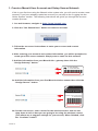
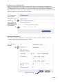
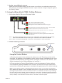
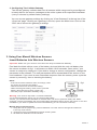
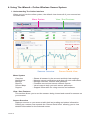
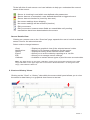
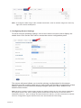
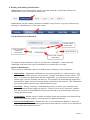
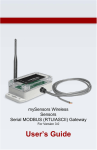
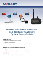
Monnit Wireless Sensors
and Cellular Gateway
Quick Start Guide
Inside the Box
You should find the following items in the box:
• Monnit™ Wireless Sensors
• MonnitLink™ Wireless Cellular Gateway
• Power Supply
• Antenna
• Mounting Hardware
• Quick Start Guide
• Batteries
MonnitLink™ Cellular Gateway Quick Start
• Create an iMonnit user account and assign wireless gateway and sensors.
• Plug the power supply into a power outlet then connect to the gateway.
• Once all three lights turn green, your network is ready to bring sensors online.
IMPORTANT!
DO NOT plug your Cellular Gateway in until after you have created an account on
iMonnit.com and added your cellular gateway and wireless sensors to the account.
1. Create a Monnit User Account and Setup Sensor Network
If this is your first time using the iMonnit online system site, you will need to create a new
account. If you have already created an account you can skip to the “Logging into the
Online System” section. The following instructions will guide you through the account
creation process.
1. In a web browser, navigate to https://www.imonnit.com.
2. Click the “Get Started Here” button to create an account.
3. Follow the on-screen instructions to enter your account and contact
information.
4. After entering your account and contact information, you will be prompted to
create your first sensor network. Simply enter a name for this network.
5. Add the information from your MonnitLink™ gateway then click the
“Assign Gateway” button.
ID: ZTL-RFUSB1
IC: 9794A-RFUSB1
ID: #### Code: XXXXXX
Pe
Back of
+
_
el
6a. Add the information from your first Monnit wireless sensor then click the
“Assign Sensor” button.
Sensor
Contains: FCC ID: ZTL-RFSC1
IC: 9794A-RFSC1
Sensor ID: ######
Sensor Code: XXXXXX
6b. On the next screen, enter a name for the wireless sensor and use the
drop down to tell us how you are going to be using the wireless sensor.
(This allows us to suggest settings for your sensor.) When finished, click
the “Continue” button.
PAGE 2
7. Setup sensor notification(s).
The next screen will allow you to setup notifications for the sensor that was just
added to the network. You have the option of using pre-configured notifications based
on suggestions from our system, or you can create your own custom notification.
If you choose to create your own notification, it will be available for any similar sensors
that are added to your account in the future.
Or, create your
own custom
notification here.
Select any
pre-configured
notifications you
want to use with
your sensor.
Custom notifications
To create a custom notification, click on the “Create your own” button. Set your
custom notification settings and click “Save”.
Set notification
settings.
Then click “save”.
PAGE 3
8. Assign any additional sensors.
When you have finished setting up the sensor, you will see a confirmation screen. At
this point you can assign additional sensors to your network or begin using the system
by clicking “Done”.
2. Using the MonnitLink CGW2 Cellular Gateway
1. Understanding the Ethernet Gateway Lights
1
2
3
CGW - Sensors communication problem
CGW communication with the sensors is OK
Blinking: Sensors communication with CGW is in progress
Last communication transaction with Monnit’s server was unsuccessful
Last CGW communication with Monnit’s server is OK
Blinking: CGW communication with Monnit’s server is in progress
GSM/GPRS network registration is in progress
GSM/GPRS registration is OK (CGW is registered successfully in the
GSM network)
Note 1: The CGW resets itself after receiving new configuration from the server (ex. new HB),
LED1 starts with RED and the reset cycle continues till all 3 LEDS are GREEN
Note 2: After successful SW upgrade , LED 2 and 3 flash RED then reset cycle starts.
2. Cellular Gateway Controls
Control Button
Power Switch
Using the Control Button:
1) Pressing the power button will turn the device on or off. Powering on the device
will trigger the gateway to immediately send all stored sensor messages to the online
system and download any pending system messages to deliver to the sensors. (The
default heartbeat for the cellular gateway is 5 minutes.)
2) Press and hold to Factory Reset Button to reset the gateway to factory settings.
This resets the gateway heartbeat to 5 minutes. You will need to login to the online
system after resetting the gateway to reconfigure the gateway to your desired settings.
Note: If your gateway powers up and the lights do not turn green, you may have a connectivity
issue. Wait a few minutes to see if the lights will turn green. If they do not, power off the device by
pressing the power button, then turn the device back on. If it still does not connect, try resetting
the device to the factory settings. If this still does not fix the issue, call Monit customer support.by
disconnecting then reconnecting power. If it still does not connect, try resetting the device to the
factory settings. If this still does not fix the issue, call Monit customer support.
PAGE 4
3. Configuring The Cellular Gateway
The cellular gateway collects data from all sensors within range and is preconfigured
to batch deliver the sensor messages to the online system at the specified heartbeat
(every 5 minutes by default factory settings).
You can access gateway settings by clicking on “View Gateways” in the top bar of the
“Overview” page. Clicking on a gateway in the list, opens the detail view. Click on the
“Edit” tab to access the gateway’s settings.
3. Using Your Monnit Wireless Sensors
Insert Batteries Into Wireless Sensors
Important: Make sure your sensors are at least 3ft. away from Ethernet Gateway.
Peel back the black sticker cover of the battery slot and slide the coin cell battery into
the sensor as shown in fig.1. It will power on within 10-20 seconds. Once online, your
sensor is ready to be deployed. If you wish to change a sensor configuration, change the
parameter in the software. The new parameters will be transmitted to the sensor on the
next heartbeat. If you need a more immediate response from the sensor, power cycle the
sensor by removing, then re-inserting the battery.
Notes:
- If the sensor status indicator does not change, reset
the sensor by removing the battery.
- Wait 60 seconds then re-insert the battery.
- When inserting the battery, make sure to push the
battery all the way back using a paper clip.
- Note the proper orientation of battery in fig.1
Battery
Insertion
fig.1
+
_
Warning: Your sensors ship with a 10 minute heartbeat.
It is recommended that unless you are using the AA battery
solution, you should set the heartbeat to no faster than one hour to preserve battery life. When
changing a sensor’s heartbeat, the new configuration information will be sent to the sensor on it’s next
heartbeat. If you want to update the sensors immediately you can reset them manually.
Manual Sensor Reset Process:
1 - Using the end of a paper clip, push the batteries out of the sensors through the small hole
in the top of the sensor
2 - Change the sensor heartbeat through the online system
3 - Re-insert the batteries into the sensors
PAGE 5
4. Using The iMonnit™ Online Wireless Sensor System
1. Understanding The Online Interface
When you log into the online system, the default view shows all of your sensors last
recorded data.
Menu System
View / Sort Features
Date Range Selector
Sensors Overview
Sensor Details View
Menu System
Overview
Notifications
Manage
Reports
Sensor Maps
Support
- Shows all sensors in the account and their last readings.
- Manage sensor notifications and show all sent notifications.
- Manage networks, sensors and gateways.
- Printable account and sensor network reports.
- Visual maps to help you track sensor placement.
- Support information for using sensors and software.
View / Sort Features
This section allows you to sort the sensors being viewed and search for sensors on
your account.
Sensor Overview
Displays sensors on your account with their last reading and status information.
Clicking on a sensor row expands the “Sensor Detail View” allowing you to view
detailed information for the selected sensor.
PAGE 6
To the left side of each sensor row is an indicator to help you understand the current
status of the sensor.
Sensor is checking in and within user defined safe parameters.
Sensor has met or exceeded a user defined threshold or triggered event.
Sensor has not checked in (inactivity alert sent).
No sensor readings since shipping
No sensor readings will be recorded (Inactive)
Edit your sensor
Edit your sensor, however some fields are unavailable until pending
transactions have been downloaded to the sensor
Sensor Details View
Clicking on a sensor row on the “Overview” page expands the row to include a detailed
sensor view for the selected sensor.
Select a tab to change between:
Chart
Notifications
History
Export
Edit
Calibrate
- Displays a graphical view of the selected sensor’s data.
- Allows you to manage notifications for the sensor.
- Displays a history of the selected sensor’s data.
- Allows you to archive data by exporting as a .csv file.
- Allows you to manage sensor settings.
- Available on certain sensor types to provide more accurate data.
Note: The data shown on the chart, notification, history and export tabs is based on the date
range indicated on the upper right side of the sensor detail information. To change the date
range, click inside the date box.
2. Chart and History Views.
Clicking on the “Chart” or “History” tabs within the sensor detail panel allows you to view
the sensor’s data history in a graphical chart format or as text.
PAGE 7
Note: To change the date range of the viewable information, click on the date range box at the top
right of the sensor detail panel.
3. Configuring Sensor Settings
To edit a sensors operation settings, click on the sensor overview row to display the
details view. Click on the “Edit” tab to access the sensor configuration panel.
The sensor edit panel allows you to set the primary configurations for the sensor.
Mousing over the question mark icon by each setting will provide an explanation of that
setting. When you have finished making changes, press the “Save” button at the
bottom of this section.
Note: Be sure to click the “Save” button anytime you make a change to any of the sensor parameters.
All changes made to the sensor settings will be downloaded to the sensor on the next sensor
heartbeat (check-in). Once a change has been made and “Saved,” you will not be able to edit that
sensor’s configurations again until the sensor has downloaded the new setting.
PAGE 8
4. Editing and Adding Notifications
Notifications for a single sensor can be created, deleted or edited by clicking the
“Notifications” tab in a sensor’s detail view.
Notifications can be created, deleted or edited for any sensor or group of sensors by
clicking on “Notifications” in the main menu.
The Notification List Window
Create a New
Notification
Click to Enable /
Disable a
Notification
Edit Notification
View / Edit / Delete
Notification
To create a new notification, click on “Create new notification”, then name the
notification and select the type of notification you would like to create.
Class of Notification
There are four notification options available when creating a new notification.
• Application - Application notifications are sensor specific (i.e. water sensor = trigger alert when water present, temp sensor = trigger alert when temp is above 70F,
etc.). If creating an application specific notification, you will need to choose what
sensor type you are creating the alert for. The system will automatically populate a
list of sensor types that are currently being used within the network. The notificatiion
you create will be based on the selected sensor type.
• Inactivity - Set-up “Inactivity” notifications to alert you when your sensors have
stopped communicating with the servers. Failure to set up an “Inactivity” notification will result in no email/SMS txt being sent should your sensors stop communicating with the servers.
• Low battery - Allows users to define a battery power percentage level that will trigger an alert from the system, warning them to replace batteries.
• Advanced Notifications - Allows the user to set notifications based on more advanced rules, such as comparing past data points with the current one to determine
if the notification should be sent.
PAGE 9
Setting and Editing Notification Settings
People to Notify
Start typing a name into the box and the system will automatically populate the
name of a user within your sensor network. If there are already multiple users on
the network, a drop down list of names will appear. Select the name of the user
for the notification. If the person to be notified does not have an account on the
network, you may quick add them by selecting the “Add Recipient” link and entering
in their contact information.
Notification Parameters
This area allows the user to set notification parameters such as naming the
notification, customizing the notification message and setting sensor conditions that
will trigger the notification.
Assigned Devices
Allows you to tell the system which sensor(s) will trigger the notification being
created. When a notifications is sent from the system, it will automatically include
the sensor name and data that caused the notification to be sent.
A notification can be assigned to multiple sensors. Application specific notifications
(ex. Temperature) can only be assigned to sensors of that application type. General
notifications such as “battery status”, can be assigned to any or all sensors.
5. Exporting Sensor Data
Clicking on the “Export” tab within the sensor data window allows you to export sensor data
to a comma separated value (.csv) file or send the sensor data to an external web source.
To export sensor data you must first select the date range for the data you want to export.
Once the date range is selected, determine whether you want sensor data from the
selected sensor only, from all sensors in the network or all sensors assigned to the account.
When you are finished, click on “Export Data” at the bottom of this window. The data will be
exported to a comma separated value (.csv) file format.
Note: Only the first 2,500 records within the selected date range will be exported.
You can alternately send your sensors’ incoming data to a 3rd party by clicking on the
“Configure data push” button at the bottom of the window. From this area you can pass
data from your wireless sensor network devices to another service in real time. This is done
by coding the data into a url query then sending the data via http get request at the time
data is received. There is an extensive list of parameters that can be passed, as listed in
the viewed window, that allow you to send detailed information about both the data and the
sensor.
PAGE 10
6. Calibrating Sensor Data
Certain wireless sensors can be calibrated for more accurate readings (ex. temperature
sensors). If calibration is possible for a sensor, the “Calibrate” tab will be visible in the detail
view. To calibrate a sensor, replace the last reading with the more accurate reading and
click “Calibrate”. All future readings from the sensor will be based off the new calibration
setting.
7. Manage Sensor Networks
To view or edit information about your wireless sensor network(s), click on “Manage” in the
main navigation. This area allows you to edit network details, create new sensor networks,
and manage wireless gateways and sensors for your network(s).
Click to
Manage
Create a
new network
Select which
network to view
Edit network
information
Add a device
to the network
Remove device
from network
Clear sensor
history and data
Move device
to
PAGE 11
another network
Note: Some buttons and features are only visible if there is more than one sensor network setup on the
account, such as the network selection box in the upper right corner.
If more than one sensor network is setup on the account, you can easily move gateways and sensors
from one network to another by clicking on the “Move Device” button at the far right of the device’s
“Status” section.
If you clear a sensor’s data, the data history is deleted from the entire system and can not be recovered.
We recommend exporting a sensor’s data history using the export function in the sensor details view
(“Overview” page) before clearing the sensor’s data if you want to have a record of the data.
PAGE 11
Additional Information and Support
You can find additional information on using Monnit Wireless Sensors, including product
documentation and video tutorials on the Monnit website at http://www.monnit.com/support.
Information to Users
The Monnit wireless products referenced in this Quick Start Guide have been tested and found to comply
with the standards for FCC, IC and CE certifications. For certification information on individual products
please view product data sheets or product specifications on the Monnit website.
Industry
Canada
WARNING: Changes or modifications not expressly approved by Monnit could void the user’s authority to operate the equipment.
For additional information or more detailed instructions on how to use your Monnit
Wireless Sensors or the iMonnit Online System, please visit us on the web at
http://www.monnit.com/support/.
Monnit Corporation
7304 South Cottonwood
Suite #204
Midvale, Utah 84047
801-561-5555
www.monnit.com
All trademarks are property of Monnit. ©2013 Monnit Corp. All Rights Reserved.
M-QS04-2B (12/13)