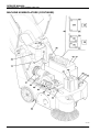
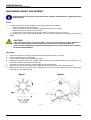
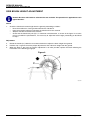
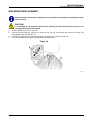
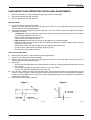
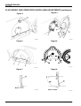
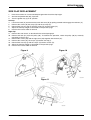
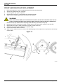
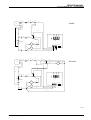
1
Terra 128B - 132B
SERVICE MANUAL
146 0721 000(2)2003-04
SERVICE MANUAL
INDEX
GENERAL INFORMATION
MACHINE LIFTING
MACHINE TRANSPORTATION
OTHER AVAILABLE MANUALS
SAFETY - ACCIDENT PREVENTION
GENERAL SAFETY RULES
TECHNICAL DATA
MAINTENANCE
SCHEDULED MAINTENANCE
SCHEDULED MAINTENANCE TABLE
MACHINE NOMENCLATURE
3
3
3
3
4
4
5
7
7
7
8
SWEEPING SYSTEM
VISUAL INSPECTION OF THE BELT FROM THE ENGINE TO THE MAIN BRUSH
BELT REPLACEMENT FROM THE ENGINE TO THE MAIN BRUSH
MAIN BRUSH HEIGHT ADJUSTMENT
MAIN BRUSH REPLACEMENT
SIDE BRUSH HEIGHT ADJUSTMENT
SIDE BRUSH REPLACEMENT
MAIN MOTOR ELECTRICAL INPUT CHECK
MAIN MOTOR BRUSH/CARBON BRUSH CHECK AND REPLACEMENT
MAIN BRUSH AND REDUCTION UNIT REPLACEMENT
SIDE BRUSH MOTOR ELECTRICAL INPUT CHECK
SIDE BRUSH MOTOR REPLACEMENT
TROUBLESHOOTING
11
11
11
12
13
14
15
16
18
19
22
23
24
FLAP
FLAP HEIGHT AND OPERATION CHECK (AND ADJUSTMENT)
SIDE FLAP REPLACEMENT
FRONT AND REAR FLAP REPLACEMENT
FRONT FLAP LIFTING CABLE ADJUSTMENT (only for Terra 132B)
FRONT FLAP LIFTING CABLE REPLACEMENT (only for Terra 132B)
25
25
27
28
29
31
DUST AND DEBRIS COLLECTION SYSTEM
DUST FILTER CLEANING AND INTEGRITY CHECK
FILTER-SHAKER OPERATION CHECK
FILTER-SHAKER MOTOR ELECTRICAL INPUT CHECK (optional)
TROUBLESHOOTING
33
33
34
34
35
TRACTION SYSTEM
DRIVING BELT VISUAL INSPECTION
DRIVING BELT TENSOR ADJUSTMENT
DRIVING BELT CONTROL CABLE REPLACEMENT
DRIVING BELT CONTROL CABLE SHEATH REPLACEMENT
DRIVING BELT REPLACEMENT
DRIVING WHEEL OR AXLE BEARING REPLACEMENT
TROUBLESHOOTING
36
36
36
37
38
39
40
42
OTHER SYSTEMS
SCREW AND NUT TIGHTENING CHECK
43
43
146 0721 000(2)2003-04
1
SERVICE MANUAL
ELECTRICAL SYSTEM
BATTERY MAINTENANCE AND RECHARGING
BATTERY INSTALLATION AND BATTERY TYPE SETTING (WET OR GEL)
FUSE REPLACEMENT
ELECTRONIC BOARD REPLACEMENT
HOOD SAFETY SWITCH OPERATION CHECK
CHECK IF THE MACHINE DOES NOT START WHEN THE (OPTIONAL) BATTERY CHARGER PLUG IS
CONNECTED TO THE NET OUTLET
COMPONENT LAYOUT
WIRING DIAGRAMS
44
44
44
45
46
47
47
48
50
In this manual, all the references to front part, R.H. side, L.H. side or rear part have to be intended
with the operator on the driving seat.
2
146 0721 000(2)2003-04
SERVICE MANUAL
GENERAL INFORMATION
MACHINE LIFTING
GENERAL INFORMATION
WARNING!
Do not work under the lifted machine, if it is not securely fixed.
MACHINE TRANSPORTATION
WARNING!
Before transporting the machine, ensure that:
•
All doors, drawers and carters are closed
•
The ignition key is not inserted
•
The machine is fastened to the mean of transportation
OTHER AVAILABLE MANUALS
The following manuals are available by Advance Literature Service Department:
–
Terra 128B - Spare Part List - Advance Form Number 146 0597 000
–
Terra 128B - Use and Maintenance Manual - Advance Form Number 146 0596 000
–
Terra 132B - Spare Part List - Advance Form Number 146 0788 000
–
Terra 132B - Use and Maintenance Manual - Advance Form Number 146 0791 000
146 0721 000(2)2003-04
3
SERVICE MANUAL
GENERAL INFORMATION
SAFETY - ACCIDENT PREVENTION
The following symbols indicate potentially dangerous situations. Always read carefully this information and take
the necessary precautions to protect people and objects.
DANGER!
Indicates a dangerous situation (risk of death) for the User.
WARNING!
Indicates the risk of being injured.
CAUTION!
Indicates a caution or a remark related to important or useful functions. Take care of the
paragraphs marked by this symbol.
GENERAL SAFETY RULES
Specific warnings and cautions to inform about potential damages to people and machine are shown below.
DANGER!
– To perform maintenance/repair procedures turn the machine ignition key to OFF position and
disconnect the battery.
– This machine must be used by qualified and authorized personnel only. Children or disabled
people cannot use this machine.
– Keep the battery far from sparks, flames and smoke. During the normal operation explosive
gases are delivered.
– Do not wear jewels when working near electrical components.
– Do not work under the lifted machine, if it is not securely fixed.
– Do not operate the machine near dangerous, inflammable and/or explosive powders, liquids
or vapors.
– Battery charging produces explosive hydrogen gas. Keep the hood open during battery
charging and perform the operation only in well-ventilated areas and far from naked flames.
4
146 0721 000(2)2003-04
SERVICE MANUAL
GENERAL INFORMATION
WARNING!
– Carefully read all maintenance/repair instructions before performing any maintenance/repair
procedure.
– Take all necessary precautions to prevent hair, jewels and loose clothes from being caught
by the machine moving parts.
– Do not smoke during battery charging.
– Do not leave the machine unattended with the ignition key inserted and the parking brake
deactivated.
– Do not use the machine on surfaces with a gradient greater than the one indicated on the
machine.
– Do not wash the machine with pressurized water or corrosive substances. Do not use
compressed air to clean this type of machine.
– Do not use the machine in too dusty areas.
– While using this machine take care not to cause damage to people.
– Storage temperature must be within +32°F - +104°F (0°C - +40°C).
– The machine working temperature must be within +32°F - +104°F (0°C - +40°C).
– Humidity range should be within 30% and 95%.
– Do not use the machine as a transport vehicle.
– Do not allow the brushes to operate while the machine is stationary to avoid damaging the
floor.
– In case of fire, use a powder extinguisher. Do not use water.
– Do not remove or modify the plates affixed on the machine.
– If parts must be replaced, require ORIGINAL spare parts from a Dealer or Authorized Retailer.
– The machine must be disposed of properly, because of the presence of toxic-harmful
materials (battery acid, oil, etc.), which are subject to standards that require disposal in
special centers (see the related chapter in the Use and Maintenance Manual).
– When lead batteries (WET) are installed on this machine, do not tilt the machine more than 30°
from its horizontal position to not allow the highly corrosive acid to leak out of the batteries.
When it is necessary to tilt the machine for maintenance, remove the batteries.
TECHNICAL DATA
Dimensions
Cleaning width (with side brush)
Terra 128B
Terra 132B
700 mm (27.6 in)
820 mm (32.3 in)
Minimum machine length
Machine width, without side brush
1070 mm (42.13 in)
667 mm (26.26 in)
773 mm (30.4 in)
Height when the handlebar is
lowered
836 mm (32.91 in)
Minimum height from ground
40 mm (1.6 in)
Handlebar height,
minimum/maximum
Main brush size
824 /1120 mm (32.4 / 44 in)
Ø 245 mm x 500 mm
(9.65 x 19.69 in)
Side brush size
Speed with maximum push force
Ø 347 mm (13.7 in)
4,24 Km/h (2.63 mph)
Maximum slope
Hopper capacity
Machine total weight
Front wheel, steering
Ø 245 mm x 600 mm
(9.65 x 23.62 in)
4,38 Km/h (2.74 mph)
2%
40 Lt (1.4
ft3)
94,78 Kg (210.62 lb)
50 Lt (1.7 ft3)
100,9 Kg (222.4 lb)
Ø 125/37.5-50 mm (4.92/1.48-1.97 in)
Continues
146 0721 000(2)2003-04
5
SERVICE MANUAL
GENERAL INFORMATION
Rear wheels, driving
Ø 250 x 50 mm (Ø 9.84 x 1.97 in)
Main electric motor
600 W - 3000 RPM
Sound level (Lpa)
64 dB (A)
Electric filter-shaker (optional)
12 V, 30 W
Batteries
Terra 128B
Terra 132B
Standard battery
Lead, with acid electrolyte (WET)
Optional battery
Gel, hermetic (GEL)
Battery voltage
12 V
Battery compartment max. size
398x262x283 (15.7x10.3x11.1 in)
Dust suction and filtering
Terra 128B
Terra 132B
2
2 m (22
Paper dust filter 5-10 µm
Electric filter-shaker (optional)
ft2)
12V, 30 W
Vacuum in main brush
compartment
4 mm H2O (0.63 in H2O)
(*) 1062,8 mm (41.8 in)
(**) 1060,2 mm (41.7 in)
(*) (**)
541,3 mm (21.3 in)
(*) 353,8 mm (13.9 in)
(**) 382,8 mm (15.1 in)
(*) 671,2 mm (26.4 in)
(**) 772,9 mm (30.4 in)
(*) 666,8 mm (26.3 in)
(**) 766,8 mm (30.2 in)
(*) 612,9 mm (24.1 in)
(**) 712,9 mm (28.1 in)
(*) 939,7 mm (37 in)
(**) 938,8 mm (37 in)
(*) = Terra 132B
(**) = Terra 132B
S300366
6
146 0721 000(2)2003-04
SERVICE MANUAL
GENERAL INFORMATION
MAINTENANCE
SCHEDULED MAINTENANCE
The machine proper and safe operation is granted by a careful and constant maintenance.
See GENERAL INFORMATION and SAFETY - ACCIDENT PREVENTION
The following table sums up the scheduled maintenance. The indicated periods can be subjected to variations
according to working conditions. These must be defined by the person in charge of maintenance.
For maintenance operation instructions see the following paragraphs.
SCHEDULED MAINTENANCE TABLE
On delivery
Every
10
hours
Battery liquid level check
!
! (1)
Driving belt visual inspection:
traction, main brush
!
Flap height and operation check
!
Maintenance operation
Every
200
hours
Every
400
hours
!
!
Dust pre-filter cleaning and integrity
check
! (1)
!
!
Nut and screw tightening check
Drive belt check and tensor
adjustment
Every
100
hours
!
Side and main brush height check
Filter-shaker operation check
Every
50
hours
!
Driving belt replacement: traction,
main brush
!
Main electric motor brush (or
carbon brush) check or
replacement
!
Hood opening switch operation
check
!
Check if the machine does not start
when the (optional) battery charger
plug is connected to the net outlet.
!
(1): Or before each start.
146 0721 000(2)2003-04
7
SERVICE MANUAL
GENERAL INFORMATION
MACHINE NOMENCLATURE
In this Manual you find numbers in brackets – example: (2). These numbers refer to the components indicated in
these two nomenclature pages. Refer to these pages each time you want to find the component mentioned in the
text.
1.
2.
3.
4.
5.
6.
7.
8.
9.
10.
11.
12.
13.
14.
15.
16.
17.
18.
19.
20.
21.
22.
23.
24.
25.
26.
27.
28.
29.
30.
8
Control panel
Ignition key
Discharged battery warning light
Semi-discharged battery warning light
Charged battery warning light
Display
Display selection button: hour counter/ hour and minutes
counter / battery voltage (V),
Filter-shaker button (optional)
Panel fastening screws
Serial number plate / technical data / EC certification
Machine serial number
Handlebar
Selector lever
Handlebar inclination adjusting knobs
Can holder
Hood
Rear wheels on fixed axis
Pivoting front wheel
Side brush
Main brush (inside)
Side brush lifting and adjusting knob
Side brush retainer
Lift side flap
Right side flap
Front flap
Rear flap
Hopper
Hopper hook
Hopper hook handle
Manual filter-shaker handle
31.
32.
33.
34.
35.
36.
37.
38.
39.
40.
41.
42.
43.
44.
45.
46.
47.
48.
49.
50.
51.
52.
53.
54.
55.
56.
57.
Main brush movable door
Main brush height left adjuster
Main brush height right adjuster
Main brush right door
Main brush right door fastening screws
Pedal brake on front wheel (optional)
Batteries
Battery connector
Battery charger
Battery charger electrical cable
Main fuse
Side brush motor fuse
(Lead) battery caps
Lead (WET) or gel (GEL) battery selector switch positioned on
the electronic battery charger
Battery assembly diagram
Charged battery warning light
Main brush belt
Drive belt
Drive pulley to main brush
Drive pulley to traction
Fan
Main electric motor
Hood safety switch
Battery charger electrical connector (brown) (prearrangement)
Front flap lifting lever (*)
Ground discharge chain
Key fuse
(*) Only on Terra 132B
146 0721 000(2)2003-04
SERVICE MANUAL
GENERAL INFORMATION
MACHINE NOMENCLATURE (CONTINUES)
S300367
146 0721 000(2)2003-04
9
SERVICE MANUAL
GENERAL INFORMATION
MACHINE NOMENCLATURE (CONTINUES)
S300368
10
146 0721 000(2)2003-04
SERVICE MANUAL
SWEEPING SYSTEM
VISUAL INSPECTION OF THE BELT FROM THE ENGINE TO THE MAIN
BRUSH
SWEEPING SYSTEM
1.
2.
3.
4.
5.
6.
Drive the machine on a level ground and activate the pedal brake (36), if present.
Turn the ignition key (2) to “0” position.
Open the hood (16).
Visually inspect the timing belt (47) condition from the engine to the main brush. To check the belt completely,
rotate is by operating manually on the fan (51).
If the timing belt is worn, replace it performing the following procedure.
Carry out steps from 1. to 3. in the reverse order.
BELT REPLACEMENT FROM THE ENGINE TO THE MAIN BRUSH
1.
2.
3.
4.
5.
6.
Drive the machine on a level ground and activate the pedal brake (36), if present.
Turn the ignition key (2) to “0” position.
Remove the main brush (see the procedure in the related paragraph).
Remove the belt (47) from the pulley (49). To facilitate the operation, rotate the pulley (49) by manually
operating on the fan (51).
Remove the screws (35) and the right door (34) together with the belt (47).
Install in the reverse order of removal, with the following change:
– Set the belt tensioner (47) as shown in the figure below.
Figure 1
S300412
146 0721 000(2)2003-04
11
SERVICE MANUAL
SWEEPING SYSTEM
MAIN BRUSH HEIGHT ADJUSTMENT
Remark: Brushes with harder or softer bristles are available. This procedure is applicable to each
type of brushes.
Check
1.
Check the main brush correct height from the ground, proceeding as follows:
– Drive the machine on a level ground.
– Keep the machine stationary and rotate the main brush for a few seconds.
– Stop the main brush and move the machine.
– Check that the main brush print (A), along is width, is from 0.8 to 1.6 in (2 to 4 cm).
In case the print (A) is not within the specifications, it is necessary to adjust the brush height, proceeding as
follows.
CAUTION!
If the main brush print is excessive (above 1,6 in [4 cm]), the machine regular operation is
affected and the moving or electrical parts can overheat, thus reducing machine life.
Take care when performing the above-mentioned checks and use the machine only according
to the indicated conditions.
Adjustment
2.
3.
4.
5.
6.
7.
Drive the machine on a level ground and activate the pedal brake (36), if present.
Turn the ignition key (2) to “0” position.
Loosen the knobs (B) on both side of the machine.
Operating on the knobs (B) move, on both sides of the machine, the brush height variation indicator (C) as
necessary and then screw down the knobs (B).
The index (C) must be set to the same position on both machine sides.
Perform step 1 again to check the proper adjustment of the main brush height from the ground.
When the main brush is too worn out the adjustment is no more possible; replace the brush following the
instructions on the following page.
Figure 1
Figure 2
S300228
12
S300229
146 0721 000(2)2003-04
SERVICE MANUAL
SWEEPING SYSTEM
MAIN BRUSH REPLACEMENT
Remark: Brushes with harder or softer bristles are available. This procedure is applicable to each
type of brushes.
CAUTION!
It is advisable to use protective gloves when replacing the main brush because there can be
cutting debris between the bristles.
1.
2.
3.
4.
5.
6.
7.
8.
9.
10.
11.
12.
13.
14.
Drive the machine on a level ground and activate the pedal brake (36), if present.
Turn the ignition key (2) to “0” position.
Loosen the knobs (A) on both side of the machine.
Move the brush height variation indicators (B) until the brush reaches the maximum distance from the ground.
Screw down the knobs (A).
Open the hood (16).
On the left side of the machine, loosen the knob (C).
Remove the brush cover (D) pressing downward to disengage the retainers (E).
Pull out the brush (F).
Check that the drive hub (I) is free from dirt or foreign materials (cords, clothes, etc.) accidentally rolled up.
The new brush must be installed with the bristles rows (G) bended as shown in the figure (top view).
Install the new brush on the machine and ensure that its flange (H) correctly fits on the related drive hub (I).
Reinstall the brush cover (D), engaging the retainers (E).
Screw down the knob (C).
Carry out the Main Brush Height Adjustment as described on the previous page.
Figure 3
Figure 5
Figure 4
Figure 8
Figure 7
Figure 6
S300232
S300231
S300230
I
S300369
146 0721 000(2)2003-04
S300234
S300235
13
SERVICE MANUAL
SWEEPING SYSTEM
SIDE BRUSH HEIGHT ADJUSTMENT
Remark: Brushes with harder or softer bristles are available. This procedure is applicable to each
type of brushes.
Check
1.
Check the side brush correct height from the ground, proceeding as follows:
– Drive the machine on a level ground and lower the side brush.
– Keep the machine stationary and rotate the side brush for few seconds.
– Stop the side brush and move the machine.
– Check that the side brush print (A) is, in extension and orientation, as shown in the figure. In case the
print is not within the specifications, it is necessary to adjust the brush height, proceeding as described
in step 2.
Adjustment
2.
3.
4.
Rotate the handle (21) clockwise or counter-clockwise to adjust the brush height from ground.
Perform step 1 again to check the proper adjustment of the side brush height from the ground.
When the brush is too worn out and the adjustment is no more possible, replace the brush following the
instructions in the following paragraph.
Figure 9
S300413
14
146 0721 000(2)2003-04
SERVICE MANUAL
SWEEPING SYSTEM
SIDE BRUSH REPLACEMENT
Remark: Brushes with harder or softer bristles are available. This procedure is applicable to each
type of brushes.
CAUTION!
It is advisable to use protective gloves when replacing the side brush because there can be
cutting debris between the bristles.
1.
2.
3.
4.
Turn the ignition key (2) to “0” position.
Insert the hand inside the side brush and press the tabs (A) inward and then remove the brush (B)
disengaging it from the four pins (C).
Install the new brush on the machine engaging it on the pins (C) and on the tabs (A).
Carry out the Side Brush Height Adjustment as described above.
Figure 10
S300237
146 0721 000(2)2003-04
15
SERVICE MANUAL
SWEEPING SYSTEM
MAIN MOTOR ELECTRICAL INPUT CHECK
WARNING!
This procedure must be performed by qualified personnel only.
Discharged motor electrical input check
1.
2.
Remove the main brush (see the procedure in the related paragraph).
Open the hood (16).
WARNING!
Carry out the following operation with extreme care.
3.
4.
5.
6.
7.
16
Set an ammeter (A) on the battery positive cable (B).
Remove the side brush motor fuse (42).
Press and hold the hood safety switch (53), turn the ignition key to (2) “I” position, without pulling the selector
lever (13) and then check that the main motor electrical input is:
– Max. 50 A at 12 V, with cold engine
– Max. 45 A at 12 V, with hot engine
If the electrical input is higher, perform the following operations to detect and correct the causes:
– Remove any dirt or foreign materials from the transmission system, which can possibly hinder or slow
down regular movements.
– If necessary, carry out the motor brush check (see the procedure on the following pages).
– If necessary, disassemble the suction motor (see the procedure in the related paragraph), clean it and
check its moving parts.
If the above-mentioned procedures do not lead to a correct electrical input, it is necessary to replace the
motor (see the procedure on the following page).
Carry out steps from 1. to 4. in the reverse order.
If the electrical input with the engine discharged is correct, it is necessary to carry out the charged motor
electrical input check, according to the following procedure.
146 0721 000(2)2003-04
SERVICE MANUAL
SWEEPING SYSTEM
Charged motor electrical input check
8.
9.
10.
11.
Reinstall the main brush (see the procedure in the related paragraph).
Check that the main brush height adjustment is correct (see the procedure in the related paragraph).
Warm up the main electric motor by operating the machine for at least ten minutes.
Open the hood (16).
WARNING!
Carry out the following operation with extreme care.
12. Set an ammeter (A) on the battery positive cable (B).
13. Remove the side brush motor fuse (42).
14. Press and hold the hood safety switch (53), turn the ignition key to (2) “I” position, without pulling the selector
lever (13) and then check that the main motor electrical input is max. 55 A at 12 V.
15. If the electrical input is higher, check that the main brush height adjustment is correct (see the procedure in
the related paragraph) and then carry out steps from 10 to 14 again.
16. Carry out steps from 11. to 13. in the reverse order.
Figure 11
S300371
146 0721 000(2)2003-04
17
SERVICE MANUAL
SWEEPING SYSTEM
MAIN MOTOR BRUSH/CARBON BRUSH CHECK AND REPLACEMENT
1.
2.
3.
4.
5.
6.
7.
Drive the machine on a level ground and activate the pedal brake (36), if present.
Turn the ignition key (2) to “0” position.
Open the hood (16).
Disconnect the battery electrical connector (38) and remove the batteries (37) and the related holder.
Remove dust and dirt from the motor exterior part; then disengage and remove the clamp (A).
For each of the four brushes, lift the retaining spring (B) and remove the brushes (C).
Check if the four brushes are worn. The brushes are worn when there is not sufficient contact with the motor
armature, because of their use, of the contact surface which is not integral or because the thrust spring is
broken, etc.
8. If necessary, remove the brushes to replace them, by unscrewing the nuts (D) and disengaging the lead-in
wires (E).
9. It is advisable to replace all the brushes at the same time.
10. Install in the reverse order of removal, with the following caution:
– When connecting the terminals (E), take care of their insulation from the surrounding parts of the frame.
Figure 12
S300272
18
146 0721 000(2)2003-04
SERVICE MANUAL
SWEEPING SYSTEM
MAIN BRUSH AND REDUCTION UNIT REPLACEMENT
Removal
1.
2.
3.
4.
5.
Drive the machine on a level ground and activate the pedal brake (36), if present.
Turn the ignition key (2) to “0” position.
Open the hood (16).
Disconnect the battery electrical connector (38).
Remove the belt (47) from the pulley (49). To facilitate the operation, rotate the pulley (49) by manually
operating on the fan (51).
6. Remove the belt (48) from the pulley (50).
7. Remove the screws (9) and lift the control panel (1).
8. Disconnect the main brush cables, (A) "red" and (B) "black", from the electromagnetic switch (C) and from
the insulator (D) respectively.
9. Remove the internal retaining clamp (F) and then remove the main motor electrical cable (E) from the frame.
10. Unscrew the seven screws (G) and remove the reduction unit assembly (H).
Disassembly at the cabinet bench
11.
12.
13.
14.
15.
16.
17.
18.
19.
20.
Remove the screws (L) and the carter (M) at the cabinet bench.
Remove the screws (K) and shaft with ring gear and pulley (N, O, P) assembly.
Unscrew the screws (Q) and remove the electric motor, reduction unit, ring gear and pulley (R, S, T, U).
Unscrew the screw (V) and pull out the shaft with ring gear and pulley (W, T, U).
Remove the screws (X) and the reduction unit (S).
Loosen the dowel (Y) and remove the screw (Z).
Pull out the fan (AA) and recover the key (AB).
Remove the screw and the bracket (AC) with the motor.
Remove the screws (AD) and the main electric motor (R).
Install in the reverse order of removal.
Figure 13
Figure 14
S300240
146 0721 000(2)2003-04
S300373
19
SERVICE MANUAL
SWEEPING SYSTEM
MAIN BRUSH AND REDUCTION UNIT REPLACEMENT (Continues)
Figure 15
S300374
20
146 0721 000(2)2003-04
SERVICE MANUAL
SWEEPING SYSTEM
MAIN BRUSH AND REDUCTION UNIT REPLACEMENT (Continues)
Figure 16
S300375
146 0721 000(2)2003-04
21
SERVICE MANUAL
SWEEPING SYSTEM
SIDE BRUSH MOTOR ELECTRICAL INPUT CHECK
WARNING!
This procedure must be performed by qualified personnel only.
1.
2.
Remove the side brush (see the procedure in the related paragraph).
Remove the screws (9) and lift the control panel (1).
WARNING!
Carry out the following operation with extreme care.
3.
4.
5.
Turn the ignition key (2) to "I" position, without pulling the selector lever (13).
With an ammeter (A) on the (gray) cable (B), connecting the motor to the electromagnetic switch, check that
the motor electrical input is approximately 3 A at 12 V.
If the electrical input is higher, it is necessary to replace the motor (see the procedure on the following page).
Carry out steps from 1. to 3. in the reverse order.
Figure 17
S300244
22
146 0721 000(2)2003-04
SERVICE MANUAL
SWEEPING SYSTEM
SIDE BRUSH MOTOR REPLACEMENT
1.
Remove the battery (37) and the related holder.
WARNING!
If you do not remove the batteries before inclining the machine, serious damages to people or
the machine can occur.
2.
Operating on the handles (14), lower the handlebar (12) as shown in the figure below, then carefully lower
the machine at the back (as shown in the figure below).
3. Remove the side brush (A).
4. Remove the screw (B).
5. Remove the hub (C) and recover the key (D).
6. Remove the nut (H) and the adjusting knob (I), and recover the retaining bolt (J) and the washer (K).
7. Disconnect the electrical connector (E).
8. Remove the screws (F).
9. Remove the side brush motor (G).
10. Install in the reverse order of removal.
11. Carry out the side brush height adjustment as described in the previous paragraph.
Figure 18
S300245
146 0721 000(2)2003-04
23
SERVICE MANUAL
SWEEPING SYSTEM
TROUBLESHOOTING
THE MACHINE DOES NOT START with the key (2) to "I" position (the control panel does not activate).
Possible cause:
1. The battery connector (38) is not correctly connected (connect it)
2. The hood (16) is not correctly closed (close it)
3. The battery is discharged (charge it)
4. Possible disconnection of an electrical cable under the control panel (1) (disconnect the battery and connect
the cable)
5. For machines with battery charger, the connections must be as follows:
– Red cable: to battery positive terminal (+)
– Black cable: to battery negative terminal (-)
– Brown cable (of signal): to connector (54)
6. The key fuse (57) or the main fuse (41) are burned (replace them)
THE CONTROL PANEL ACTIVATES BUT THE MOTORS DO NOT START
Possible cause:
1. Electromagnetic switch malfunction (replace it)
2. For machines with filter-shaker, filter-shaker relay malfunction (replace it)
THE MAIN BRUSH DOES NOT ROTATE
Possible cause:
1. Dust or foreign materials hinder the operation of the main brush traction system (remove them)
2. The electric motor brushes are worn (replace them).
3. The electric motor has a malfunction (repair or replace it).
4. Drive belt from the electric motor broken (replace the belt).
5. The wiring harness is damaged (repair it).
6. The belt tensioner is malfunctioning (repair it).
7. The coupling or reduction unit are broken (repair or replace them).
THE SIDE BRUSH DOES NOT ROTATE
Possible cause:
1. Dust or foreign materials between the brush and the motor (remove them)
2. Malfunction in the electrical motor (repair or replace the electrical motor).
3. The fuse (42) is burned (replace it)
4. The wiring harness is damaged (repair it).
THE ELECTRIC MOTOR ROTATES EVEN IF THE KEY IS TO "0" POSITION
Possible cause:
1. Electromagnetic switch malfunction (replace it)
WARNING!
In this case, proceed very carefully when you disconnect the battery by the connector (38),
because the hood safety device is not working.
24
146 0721 000(2)2003-04
SERVICE MANUAL
FLAP
FLAP HEIGHT AND OPERATION CHECK (AND ADJUSTMENT)
FLAP
1.
2.
3.
Drive the machine on a level and adequate ground to check the flap height.
Activate the pedal brake (36), if present.
Turn the ignition key (2) to “0” position.
Side flap check
4.
5.
Check the side flap (23 and 24) integrity.
Replace the flaps when they have cuts (A) larger than 20 mm or cracks (B) larger than 10 mm (see the
“Service Manual” for Flap Replacement).
Check that side flap (C) height from ground is within 0 – 3 mm. (As shown) If necessary adjust the flap height,
proceeding as follows:
– Left flap (23): Open the hood (16). Loosen the knob (D) and remove the brush left cover (E) by pulling
outward to disengage the retainers (F).
Adjust the flap (G) height using its slots (H).
Install in the reverse order of removal.
– Right flap (24): Remove the main brush, as described in the related paragraph.
Remove the belt (47) from the pulley (49). To facilitate the operation, rotate the pulley (49) by manually
operating on the fan (51).
Remove the screws (35) and the right cover (34) together with the belt (47).
On the machine, adjust the flap (I) height using its slots (L).
Install in the reverse order of removal.
Front and rear flap check
6.
7.
8.
Remove the main brush, as described in the related paragraph.
Check the front (M) and rear (N) flap integrity.
Replace the flaps when they have cuts (A) larger than 20 mm or cracks (B) larger than 10 mm (see the
“Service Manual” for Flap Replacement).
9. Check that:
– The front flap (O) lightly touches the ground and that, however, it is not detached from ground (as shown
in the figure).
– The rear flap (C) height from ground is within 0 - 3 mm. (As shown)
If necessary, adjust the flap height using its slots (P).
10. (Only for Terra 132B) Activate the front flap lifting lever (55) and check that the front flap (Q) rotates upward
of 90° (as shown in figure); release the lever and check that the flap returns to the initial position and does
not stay in an intermediate one. If necessary, refer to the following pages for the adjustment or replacement
of front flap control cable.
11. Install in the reverse order of removal.
Figure 1
Figure 2
S300246
146 0721 000(2)2003-04
S300247
25
SERVICE MANUAL
FLAP
FLAP HEIGHT AND OPERATION CHECK (AND ADJUSTMENT) (continues)
Figure 4
Figure 3
S300249
S300248
Figure 6
Figure 5
P
P
M
N
S300251
S300250
Figure 8
Figure 7
S300376
26
S300377
146 0721 000(2)2003-04
SERVICE MANUAL
FLAP
SIDE FLAP REPLACEMENT
1.
2.
3.
Drive the machine on a level and adequate ground to check the flap height.
Activate the pedal brake (36), if present.
Turn the ignition key (2) to “0” position.
Left flap
4. Loosen the knob (A) and remove the brush left cover (B) by pulling outward to disengage the retainers (C).
5. Remove the screws (D) the straps (E) and the rear flap (F).
6. Reinstall the new rear flap (F) with the straps (E) and the screws (D).
7. Adjust the side flap height as described on the previous page.
8. Install in the reverse order of removal.
Right flap
9. Remove the main brush, as described in the related paragraph.
10. Remove the belt (47) from the pulley (49). To facilitate the operation, rotate the pulley (49) by manually
operating on the fan (51).
11. Remove the screws (35) and the right cover (34) together with the belt (47).
12. Remove the screws (G), the straps (H) and the rear flap (I).
13. Reinstall the new flap (I) with the straps (H) and the screws (G).
14. Adjust the side flap height as described on the previous page.
15. Install in the reverse order of removal.
Figure 9
Figure 10
S300253
S300254
Figure 11
S300255
146 0721 000(2)2003-04
27
SERVICE MANUAL
FLAP
FRONT AND REAR FLAP REPLACEMENT
1.
2.
3.
4.
5.
Drive the machine on a level and adequate ground to check the flap height.
Activate the pedal brake (36), if present.
Turn the ignition key (2) to “0” position.
Remove the main brush, as described in the related paragraph.
(Only for Terra 132B) Lightly lift the front side of the machine.
WARNING!
When lead batteries (WET) are installed on this machine, do not tilt the machine more than 30°
from its horizontal position to not allow the highly corrosive acid to leak out of the batteries.
6.
7.
8.
9.
10.
Remove the clip (E) and disconnect the lifting cable terminal (F) from the front flap (G).
Remove the screws (C) and the strap (D) and then remove the front flap (A) and/or the rear flap (B).
Reinstall the new flap (A and/or B) with the strap (D) and the screws (C).
Adjust the flap height as described on the previous page.
Install in the reverse order of removal.
(Only for Terra 132B) If necessary, refer to the following pages for the adjustment or replacement of front flap
control cable.
Figure 12
S300378
28
146 0721 000(2)2003-04
SERVICE MANUAL
FLAP
FRONT FLAP LIFTING CABLE ADJUSTMENT (only for Terra 132B)
Correct adjustment check
1.
2.
3.
4.
Drive the machine on a level ground and activate the pedal brake (36), if present.
Turn the ignition key (2) to "0" position.
Remove the main brush, as described in the related paragraph.
Activate the front flap lifting lever (55) and check that the front flap (A) rotates upward of 90° (as shown in
figure); release the lever and check that the flap returns to the initial position and does not stay in an
intermediate one.
Adjustment of the cable on the control lever
5.
Loosen the ring nut (B) and turn the screw (C) as necessary to reach the condition indicate at step 4.; tighten
the ring nut (B).
If it is not possible to achieve a correct adjustment, perform the adjustment of the cable on the flap, according
to the following procedure.
Adjustment of the cable on the flap
6.
7.
8.
Remove the hopper (27).
Open the hood (16).
Remove the battery (37).
WARNING!
If you do not remove the batteries before inclining the machine, serious damages to people or
the machine can occur.
9. Close the hood (16).
10. Operating on the handles (D), lower the handlebar (E) as shown in the figure, then carefully lower the rear
side of the machine (as shown in the figure).
11. Remove the clip (F) and disconnect the lifting cable terminal (G) from the front flap (H).
12. Loosen the nut (I) and turn the terminal (G) as necessary; tighten the nut (I). Connect the lifting cable terminal
(G) to the front flap (H), then install the clips (F).
13. Carry out step 4 again to check the correct adjustment.
Reassembly
14. Carry out steps from 3. to 6. and 10. in the reverse order.
Figure 13
S300379
146 0721 000(2)2003-04
29
SERVICE MANUAL
FLAP
FRONT FLAP LIFTING CABLE ADJUSTMENT (only for Terra 132B)
(continues)
Figure 14
S300380
Figure 15
S300381
30
146 0721 000(2)2003-04
SERVICE MANUAL
FLAP
FRONT FLAP LIFTING CABLE REPLACEMENT (only for Terra 132B)
1.
2.
3.
4.
5.
Drive the machine on a level ground and activate the pedal brake (36), if present.
Turn the ignition key (2) to "0" position.
Remove the hopper (27).
Open the hood (16).
Remove the battery (37).
WARNING!
If you do not remove the batteries before inclining the machine, serious damages to people or
the machine can occur.
6.
7.
8.
9.
10.
11.
12.
13.
14.
15.
16.
17.
18.
19.
Close the hood (16).
Operating on the handles (A), lower the handlebar (B) as shown in the figure, then carefully lower the rear
side of the machine (as shown in the figure).
Remove the clip (C) and disconnect the lifting cable terminal (D) from the front flap (E).
Loosen the nut (F) and remove the terminal (D).
Remove the nut (F) and the spring (G).
Remove the screws (9) and lift the control panel (1), and then move it laterally.
Disengage the clip (H) from the cable.
Connect a probe (cord or equivalent) to the cable end (I) (this operation is necessary to facilitate the insertion
of the cable inside the machine).
Remove the cable (L) from the machine and leave a probe in its place (to reinstall the cable later); when
removing the cable, check through the opening (M) that the electrical cables and other machine parts are
correctly routed.
Remove the flap-lifting lever fixing screws (N).
Remove the cable and the lever (O).
Carry out steps from 16. to 8. in the reverse order.
Adjust the front flap lifting cable, as described on the previous pages.
To reinstall, carry out steps from 7. to 1. in the reverse order.
Figure 16
S300382
146 0721 000(2)2003-04
31
SERVICE MANUAL
FLAP
FRONT FLAP LIFTING CABLE REPLACEMENT (only for Terra 132B)
(continues)
Figure 17
S300383
32
146 0721 000(2)2003-04
SERVICE MANUAL
DUST AND DEBRIS COLLECTION SYSTEM
DUST FILTER CLEANING AND INTEGRITY CHECK
DUST AND DEBRIS COLLECTION SYSTEM
Remark: Besides the standard paper filter, optional polyester filters are also available. The
following procedure is applicable to each type.
1.
2.
3.
4.
5.
6.
7.
8.
Drive the machine on a level ground and activate the pedal brake (36), if present.
Turn the ignition key (2) to “0” position.
Disengage the retainer (28)
By means of the handle (29) pull out the hopper (17).
Turn the handle (A) upward (90° approximately) and let the filter frame (B) rotate outward.
Pull out the pre-filter (H) and the dust filter (C) upward.
Clean the pre-filter (H).
In an outdoor area, clean the filter shaking it on a level and clean surface, tapping the side (E), opposite to
the wire gauze (F). Complete the cleaning by means of compressed air (G) of max. 6 bars (87 psi), blowing
only from the side protected by the wire gauze (F).
According to the filter type, take care of the following cautions:
– Paper filter (standard), do not use water or detergents to clean it; the filter can be damaged
– Polyester filter (optional): to clean it, see the above-mentioned instructions. For a better cleaning, it is
allowed to wash the filter with water and non-frothing detergents. This type of washing, even if it is better
for quality, reduces the life of the filter that must be replaced more frequently. The use of inadequate
detergents can damage the filter.
– Check the filter body for lacerations.
9. If necessary clean the filter compartment rubber seal (D) along its perimeter and check its integrity. If
necessary, replace it.
10. Install in the reverse order of removal, with the following caution:
– Reinstall the filter with the wire gauze (F) facing the front part of the machine.
Figure 2
Figure 1
S300415
146 0721 000(2)2003-04
S300258
33
SERVICE MANUAL
DUST AND DEBRIS COLLECTION SYSTEM
FILTER-SHAKER OPERATION CHECK
1.
2.
While using the machine, when the panel filter is supposed to be full, activate the filter-shaker proceeding as
follows, according to the type of filter-shaker installed:
– Manual filter-shaker: Pull the handle (30) outward up to the end of stroke, then release it: the interior
return spring strikes the dust filter frame and shakes it.
Repeat this operation several times.
– Electric filter-shaker (optional): press and hold the filter-shaker button (8) for a few seconds and check
that the related sound is heard.
– Restart machine operation and check if the filter has been shaken. If the filter has been shaken correctly,
the machine intake capability is greatly improved.
If necessary, check and replace the filter-shaker installed.
FILTER-SHAKER MOTOR ELECTRICAL INPUT CHECK (optional)
WARNING!
This procedure must be performed by qualified personnel only.
1.
2.
3.
Drive the machine on a level ground and activate the pedal brake (36), if present.
Remove the hopper (27).
Lift the side brush by means of the handle (21).
WARNING!
Carry out the following operation with extreme care.
4.
5.
6.
Turn the ignition key (2) to "I" position, without pulling the selector lever (13).
Activate the filter-shaker motor by means of the button (8) and, at the same time, by means of an ammeter
(A) on the cable (B), check that the filter-shaker motor (C) electrical input is approximately 3 - 5 A at 12 V. If
the electrical input is higher, it is necessary to replace the motor.
Carry out steps from 1. to 4. in the reverse order.
Figure 3
S300259
34
146 0721 000(2)2003-04
SERVICE MANUAL
DUST AND DEBRIS COLLECTION SYSTEM
TROUBLESHOOTING
THE SUCTION SYSTEM (FAN) DOES NOT ROTATE
Possible cause:
1. The battery is discharged (charge the battery).
2. The electric motor brushes are worn (replace them).
3. Main electric motor failure (repair or replace it)
4. Foreign materials obstruct the fan (remove them).
5. The wiring harness is damaged (repair it).
6. The fan is no more connected to the shaft (fixit it again)
THE FILTER-SHAKER MOTOR (optional) DOES NOT OPERATES
Possible cause:
1. Electric motor failure (repair or replace it)
2. The filter-shaker button (16) is broken (replace it)
3. Filter-shaker relay failure (replace it)
4. The wiring harness is damaged (repair it).
5. Dust accumulation in the filter-shaker motor vibrating mass case (disassemble the filter-shaker and clean it)
6. Filer-shaker motor overheating (let the filter-shaker motor cool down and try again).
146 0721 000(2)2003-04
35
SERVICE MANUAL
TRACTION SYSTEM
DRIVING BELT VISUAL INSPECTION
TRACTION SYSTEM
1.
2.
3.
4.
5.
6.
Drive the machine on a level ground and activate the pedal brake (36), if present.
Turn the ignition key (2) to “0” position.
Open the hood (16).
Visually inspect the driving belt (48) condition. Check the belt completely by turning it manually one full turn.
If the belt is worn, replace it according to the procedure indicated in the related paragraph.
Carry out steps from 1. to 3. in the reverse order.
DRIVING BELT TENSOR ADJUSTMENT
Correct adjustment check
1.
Check the tensor correct adjustment, operating according to the procedure below:
– Turn the ignition key (2) to “I” position.
– Pull carefully the selector lever (A) and check that at the first half of the stroke (B) the machine stands
still; then check that at the beginning of the second half of the stroke (C) the machine starts to move,
until it reaches the maximum speed at the end of the second half of the stroke.
If the lever operation is not correct, perform the adjustment of the cable on the lever and if necessary, on the
tensor, according to the following procedure.
Adjustment of the cable on the lever
2. Turn the ignition key (2) to “0” position.
3. Loosen the ring nut (D) and turn the screw (E); tighten the ring nut (D).
4. Carry out step 1 again to check the correct adjustment.
If a correct adjustment is not possible, perform the adjustment of the cable on the tensor, according to the following
procedure.
Adjustment of the cable on the tensor
5.
6.
7.
8.
Turn the ignition key (2) to “0” position.
Open the hood (16).
Loosen the nut (F) and turn the screw (G); tighten the nut (F).
Carry out step 1 again to check the correct adjustment.
Figure 2
Figure 1
S300260
36
S300261
146 0721 000(2)2003-04
SERVICE MANUAL
TRACTION SYSTEM
DRIVING BELT CONTROL CABLE REPLACEMENT
1.
2.
3.
4.
5.
6.
7.
8.
Drive the machine on a level ground and activate the pedal brake (36), if present.
Turn the ignition key (2) to “0” position.
Open the hood (16).
Remove the clip (A) and move the fork (B) of the driving belt control cable.
Unscrew the terminal (C) and remove it.
Pull out the cable (D) by pulling it from the side of the selector lever.
If necessary, remove the sheath (E) (see the procedure on the following page).
Install in the reverse order of removal, with the following caution:
– Do not lubricate the new control cable, as the cable exterior surface is already coated to facilitate the
correct sliding of the sheath (Teflon).
Adjust the driving belt tensor (see the procedure on the previous page).
Figure 4
Figure 3
S300262
146 0721 000(2)2003-04
S300263
37
SERVICE MANUAL
TRACTION SYSTEM
DRIVING BELT CONTROL CABLE SHEATH REPLACEMENT
1.
2.
3.
4.
5.
6.
7.
8.
9.
Remove the driving belt control cable (see the procedure on the previous page).
Turn the ignition key (2) to “0” position.
Open the hood (16).
Unscrew the nut (A) fixing the sheath on the tensor side.
Connect a probe (cord or equivalent) to the sheath end (B) (this operation is necessary to facilitate the
insertion of the sheath inside the carter).
Disengage the clip (C) from the sheath.
Move away the guard (D).
Remove the sheath by pulling it out of the plastic frame and leaving the probe in place of the sheath (for the
subsequent sheath reinstallation).
Install in the reverse order of removal, with the following change:
– When inserting the sheath by means of the probe, if it is necessary to check its correct routing, remove
the screws (9) and lift the control panel (1) after having disconnected the battery electrical connector
(38).
Figure 5
Figure 6
S300264
38
S300384
146 0721 000(2)2003-04
SERVICE MANUAL
TRACTION SYSTEM
DRIVING BELT REPLACEMENT
1.
2.
3.
4.
5.
6.
7.
8.
9.
Drive the machine on a level ground and activate the pedal brake (36), if present.
Turn the ignition key (2) to “0” position.
Remove the hopper (27).
Open the hood (16).
Remove the belt (48) from the pulley (50).
Remove the screws (A) fixing the axle to the frame, on machine both sides.
Lightly lift the machine and detach the axle with the wheels (B).
Recover the driving belt (C).
Install in the reverse order of removal.
Figure 7
S300266
146 0721 000(2)2003-04
39
SERVICE MANUAL
TRACTION SYSTEM
DRIVING WHEEL OR AXLE BEARING REPLACEMENT
1.
2.
3.
4.
5.
6.
7.
8.
9.
Drive the machine on a level ground and activate the pedal brake (36), if present.
Turn the ignition key (2) to “0” position.
Remove the hopper (27).
Open the hood (16).
Remove the belt (48) from the pulley (50).
Remove the screws (M) fixing the axle to the frame, on machine both sides.
Lightly lift the machine and detach the axle with the wheels (N).
Recover the driving belt (O).
At the cabinet bench, remove the screw (A) of the relevant wheel.
Driving wheel disassembly
10. By means of a puller (B), remove the right or left driving wheel (C or D), after having inserted a protection
washer in the threaded hole (E). (The wheel is connected to the shaft by means of a lightly forced parallel
coupling).
Recover the key (P).
The right wheel (C) is not identical to the left wheel (D) and it has a blue stamp on the internal side.
Both wheels have a red mark (I) that must be on the external part of the axle for the right wheel (C) and on
the internal part of the axle for the left wheel (D) (as shown in the figure).
Axle bearing disassembly
11. Disassemble the left driving wheel (D) and then unscrew the threaded dowels (F) and pull out the axle
bearings (G and H), recovering the flanges (L).
12. Install in the reverse order of removal, with the following change:
– Wheel (C and D) installation on the shaft, can be performed by means of a mallet.
– If the bearings (G and H) have been disassembled, their installation with dowels (F), must be performed
when installing the axle assembly on the machine frame by means of the flanges (L) to center the axle
on the frame.
40
146 0721 000(2)2003-04
SERVICE MANUAL
TRACTION SYSTEM
DRIVING WHEEL OR AXLE BEARING REPLACEMENT (continues)
Figure 8
S300267
Figure 9
S300268
146 0721 000(2)2003-04
41
SERVICE MANUAL
TRACTION SYSTEM
TROUBLESHOOTING
THE MACHINE DOES NOT MOVE
Possible cause:
1. Dust or foreign materials rolled up between the transmission elements (remove them)
2. The selector lever control cable is misadjusted or broken (adjust/replace it)
3. The driving belt (48) is broken (replace it)
4. The brake (36) is activated (deactivate it).
5. The wheel bearings do not set on the traction shaft (adjust them by means of the related dowel pins).
42
146 0721 000(2)2003-04
SERVICE MANUAL
OTHER SYSTEMS
SCREW AND NUT TIGHTENING CHECK
OTHER SYSTEMS
1.
2.
3.
4.
5.
Drive the machine on a level ground and activate the pedal brake (36), if present.
Turn the ignition key (2) to “0” position.
Remove the hopper (27).
Open the hood (16).
Remove the battery (37).
WARNING!
If you do not remove the batteries before inclining the machine, serious damages to people or
the machine can occur.
6.
Carry out the following checks:
– Accessible fixing screw and nut tightening
– Other fixing element proper position
– Other component and item visible faults.
7. Close the hood (16).
8. Operating on the handles (14), lower the handlebar (12) as shown in the figure below, then carefully lower
the machine at the back (as shown in the figure below).
9. Under the frame, check the following:
– Accessible fixing screw and nut tightening
– Other fixing element proper position
– Other component and item visible faults.
10. Carry out steps from 1. to 5. and 8. in the reverse order.
Figure 1
S300269
146 0721 000(2)2003-04
43
SERVICE MANUAL
ELECTRICAL SYSTEM
BATTERY MAINTENANCE AND RECHARGING
ELECTRICAL SYSTEM
See Use and Maintenance Manual
BATTERY INSTALLATION AND BATTERY TYPE SETTING (WET OR GEL)
Battery type selection
1.
2.
3.
The machine can be equipped with the following types of batteries:
– Lead battery, with acid electrolyte
– Gel battery, hermetic
To identify battery voltage and capacity, see chapter Technical Data.
To assemble the battery on the machine, see the diagram (45).
Battery removal
4.
5.
6.
7.
8.
Drive the machine on a level ground and activate the pedal brake (36), if present.
Turn the ignition key (2) to “0” position.
Open the hood (16).
Disconnect the battery electrical connector (38).
Remove the battery (37).
New battery installation
9.
According to the battery type selected (lead or gel), before connecting the battery to the machine electrical
system, the machine electronic board and the battery charger (if installed on the machine) must be set,
performing the following operations:
Machine electronic board setting
10. Remove the screws (9) and carefully pull out the control panel (1).
11. Operating on the electronic board, install a jumper wire (A) on the “WET” connectors (C) for lead battery or
on the “GEL” connectors (D) for gel battery.
12. Reinstall the control panel (1) and tighten the screws (9).
Battery charger setting
13.
14.
15.
16.
Take the battery charger selector (44) to (WET) for lead battery, or to (GEL) for gel battery.
Install the battery on the machine according to the diagram (45) and connect the electrical cables.
Connect the battery electrical connector (38).
Charge the battery (see the procedure in the Use and Maintenance Manual).
Figure 1
S300270
44
146 0721 000(2)2003-04
SERVICE MANUAL
ELECTRICAL SYSTEM
FUSE REPLACEMENT
1.
2.
3.
4.
Drive the machine on a level ground and activate the pedal brake (36), if present.
Turn the ignition key (2) to “0” position.
Open the hood (16).
Disconnect the battery electrical connector (38).
60 A fuse (main fuse) replacement
5.
Remove the guard (41) and pull out the underlying 60 A fuse.
15 A fuse (side brush motor fuse) replacement
6.
Pull out the 15 A fuse (42).
10 A fuse replacement (Key-electronic board fuse)
7.
Pull out the 10 A fuse (57).
Reset
To reset the machine, install in the reverse order of removal.
146 0721 000(2)2003-04
45
SERVICE MANUAL
ELECTRICAL SYSTEM
ELECTRONIC BOARD REPLACEMENT
1.
2.
3.
4.
5.
6.
7.
8.
Drive the machine on a level ground and activate the pedal brake (36), if present.
Turn the ignition key (2) to “0” position.
Open the hood (16).
Disconnect the battery electrical connector (38).
Remove the screws (9) and lift the control panel (1).
Disconnect the electrical connector (A).
Remove the electronic board (B) by disconnecting the screws (C).
Install in the reverse order of removal, with the following change:
– The new electronic board must be aligned (set) to the battery type (37) installed on the machine,
according to the following procedure:
– Install a jumper wire (D) on the “WET” connectors (E) for lead battery, or on the “GEL” connectors (F)
for gel battery.
Figure 2
S300272
46
146 0721 000(2)2003-04
SERVICE MANUAL
ELECTRICAL SYSTEM
HOOD SAFETY SWITCH OPERATION CHECK
1.
2.
3.
4.
5.
6.
7.
With the machine off, open the hood (16).
Try to start the machine by turning the ignition key (2) to "I" position and check that it is not possible to start
the machine.
Close the hood (16).
Start the machine by turning the ignition key (2) to "I" position.
Open the hood (16) and check that the machine turns off immediately.
Turn the ignition key (2) to "O" position.
Close the hood (16).
CHECK IF THE MACHINE DOES NOT START WHEN THE (OPTIONAL)
BATTERY CHARGER PLUG IS CONNECTED TO THE NET OUTLET
1.
2.
3.
With the machine off, insert the battery charger electrical cable plug (40) in the electrical net outlet.
Try to start the machine by turning the ignition key (2) to "I" position and check that it is not possible to start
the machine.
Disconnect the electrical cable plug (40) from the net.
146 0721 000(2)2003-04
47
SERVICE MANUAL
ELECTRICAL SYSTEM
COMPONENT LAYOUT
Remark: The symbol in brackets (..) after the name of the component refers to the wiring
diagram (see the following pages).
1.
2.
3.
4.
5.
6.
7.
8.
9.
10.
11.
12.
13.
14.
15.
16.
17.
18.
19.
20.
21.
22.
48
Main motor (M1)
Side brush motor (M2)
Filter-shaker motor (M3)
Control panel
Ignition switch (SW1)
Discharged battery warning light
Semi-discharged battery warning light
Charged battery warning light
Display
Display selection button: hour counter/ hour and minutes counter / battery voltage (V)
Filter-shaker button (optional) (SW3)
Electronic board (EB1)
Battery connector (CN1)
60 A main fuse (F1)
15 A side brush motor fuse (F2)
10 A key fuse (F3)
Electromagnetic switch (ES1)
Insulator
Battery charger (CH1)
Battery charger connector (CN2)
Filter-shaker relay (R1)
Hood safety switch (SW2)
146 0721 000(2)2003-04
SERVICE MANUAL
ELECTRICAL SYSTEM
Figure 3
S300385
146 0721 000(2)2003-04
49
SERVICE MANUAL
ELECTRICAL SYSTEM
WIRING DIAGRAMS
Wiring diagrams for optional equipments:
1. Standard
2. With filter-shaker
KEY
CH1
CN1
CN2
EB1
ES1
F1
F2
F3
M1
M2
M3
R1
SW1
SW2
SW3
Battery charger
Battery connector
Battery charger connector
Electronic board
Electromagnetic switch
Main fuse (60A)
Side brush fuse (15A)
Key fuse (10A)
Main brush motor
Side brush motor
Filter-shaker motor
Filter-shaker relay
Key switch
Hood safety switch
Filter-shaker switch
COLOR CODE
BK
Black
BU
Blue
BN
Brown
GN
Green
GY
Grey
OG
Orange
PK
Pink
RD
Red
VT
Violet
WH
White
YE
Yellow
50
146 0721 000(2)2003-04
SERVICE MANUAL
ELECTRICAL SYSTEM
CN2
SW2
BN
F3
SW1
WH
WH
OG
CH1
STANDARD
OG
BU
BK
RD
RD
CN1
RD
F1
ES1
RD
+
GY
EB1
+
BATTERIES 12V
GY
M2
-
F2
V-
BK
BK
CN1
CN2
Gel Pb
RD
M1
BK
Out V+
BK
SW2
BN
F3
SW1
SW3
WH
WH
OG
BK
BN
CH1
R1
OG
RD
M3
BK
WITH SHAKER
OG
YE
BU
BK
RD
RD
CN1
RD
F1
ES1
RD
+
GY
EB1
+
BATTERIES 12V
M2
-
GY
F2
V-
BK
BK
BK
CN1
M1
Out V+
Gel Pb
RD
BK
BK
S300416
146 0721 000(2)2003-04
51
SERVICE MANUAL
ELECTRICAL SYSTEM
52
146 0721 000(2)2003-04
Nilfisk-Advance, Inc.
14600 21st Avenue North
Plymouth, MN, 55447-3408
www.nilfisk-advance.com
Phone:
800-989-2235
Fax:
800-989-6566
©2003 Nilfisk-Advance, Inc.,
Plymouth, MN 55447-3408
Printed in Italy