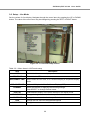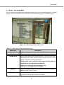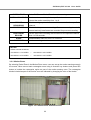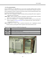
1
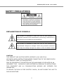
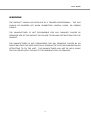
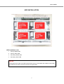
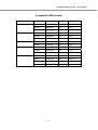
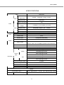
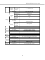
EST9120/EST16120 User Guide USER GUIDE EST9120/EST16120 9/16 channel MPEG-4 Triplex DVR V. 1.5 This document contains preliminary information and subject to change without notice. EST9120/EST16120 User Guide SAFETY PRECAUTIONS EXPLANATION OF SYMBOLS This symbol is intended to alert the user to the presence of important operation and maintenance (servicing) instructions in the literature accompanying the appliance. This symbol is intended to alert the user to the presence of unprotected “dangerous voltage” within the product’s enclosure that may be strong enough to cause a risk of electric shock CAUTION THIS PRODUCT HAS MULTIPLE-RATED VOLTAGES (110V AND 220V). SEE INSTALLATION INSTRUCTIONS BEFORE CONNECTING TO THE POWER SUPPLY. THIS PRODUCT USES A LITHIUM BATTERY. RISK OF EXPLOSION IF THE BATTERY ON THE MAIN BOARD IS REPLACED BY AN INCORRECT TYPE. DISPOSE OF USED BATTERIES ACCORDING TO INSTRUCTIONS. THIS EQUIPMENT AND ALL COMMUNICATION WIRINGS ARE INTENDED FOR INDOOR USE. TO REDUCE THE RISK OF FIRE ELECTRIC SHOCK, DO NOT EXPOSE THE UNIT TO RAIN OR MOISTURE. 2 User Guide WARNING THE PRODUCT SHOULD BE INSTALLED BY A TRAINED PROFESSIONAL. THE DVR SHOULD BE POWERED OFF WHEN CONNECTING CAMERA, AUDIO, OR SENSOR CABLES. THE MANUFACTURER IS NOT RESPONSIBLE FOR ANY DAMAGES CAUSED BY IMPROPER USE OF THE PRODUCT OR FAILURE TO FOLLOW INSTRUCTIONS FOR THE PRODUCT. THE MANUFACTURER IS NOT RESPONSIBLE FOR ANY PROBLEMS CAUSED BY OR RESULTING FROM THE USER PHYSICALLY OPENING THE DVR FOR EXAMINATION OR ATTEMPTING TO FIX THE UNIT. THE MANUFACTURER MAY NOT BE HELD LIABLE FOR ANY ISSUES WITH THE UNIT IF THE WARRANTY SEAL IS REMOVED. 3 EST9120/EST16120 User Guide THE LIST OF CONFIGURATION DVR SET CLIENT SOFTWARE CD REMOTE CONTROLLER BATTERY MANUAL (SERVER & REMOTE CLIENT S/W) RUBBER RINGS & SCREWS (4x4x4EA) IDE HDD CABLE(2EA) HDD BRACKETS(4EA) POWER CABLE 110V & 220V 4 User Guide THE OPERATION OF REMOTE CONTROLLER POWER Power On/Off ID (DVRs) Input DVR ID (ID : i.e. 00 or 01) F/REW Jump 60 seconds backward PLAY Play/Pause F/ADV Jump 60 seconds forward REW Rewind (X1, X2, X4, X8) FREEZE/CAP Freeze/Capture for Still Image FF Fast Forward (X1, X2, X4, X8) ALARM Disable alarm operation LOCK/ SETUP Key lock of all of the functions /Setup menu screen ARCHIVE Display of archive list AUDIO Disable, Mute or Highlighted channel only DISPLAY Change division (1->4->9->16) SEQ Sequence of Full or Quad view RECORD Manual recording SEARCH Search menu screen DIRECTION Direction or number 1 to 4 SELECT Enter and Save button SETUP Setup or Menu button ESC Esc PTZ PTZ menu screen NUMBER Channel 1 to 9 +10 Channel 10 and channel 11 to16 10CH->press +10 and number 0 11CH->press +10 and number 1 12CH->press +10 and number 2 13CH->press +10 and number 3 14CH->press +10 and number 4 15CH->press +10 and number 5 16CH->press +10 and number 6 5 EST9120/EST16120 User Guide VIDEO SIGNAL SELECT / SETTING SETTING Video mode Video output NTSC PAL BNC VGA O X O X X O O X O X X O X O X O NOTICE Do not change the setting when the power is on. When the position of the switch is changed, the DVR should be rebooted to apply the new setting. 6 User Guide HDD INSTALLATION HDD installation order 1. Primary Master HDD 2. Primary Slave HDD 3. Secondary Master HDD 4. Secondary Slave HDD NOTICE The brands and models of all HDD should be the same. If the brands and models of each HDD are different with others, the DVR could not recognize HDD. 7 EST9120/EST16120 User Guide Compatible HDD models BRAND CAPACITY RPM BUFFER INTERFACE HITACHI 80GB 7200RPM 2M E-IDE 160GB 7200RPM 8M E-IDE 250GB 7200RPM 8M E-IDE 80GB 7200RPM 2M E-IDE 160GB 7200RPM 8M E-IDE 250GB 7200RPM 8M E-IDE 80GB 7200RPM 2M E-IDE 160GB 7200RPM 2M E-IDE 80GB 7200RPM 2M E-IDE 160GB 7200RPM 8M E-IDE 250GB 7200RPM 8M E-IDE 40GB 7200RPM 2M E-IDE 80GB 7200RPM 2M E-IDE 160GB 7200RPM 2M E-IDE 250GB 7200RPM 2M E-IDE MAXTER SAMSUNG WESTERN DIGITAL SEAGATE 8 User Guide SPECIFICATIONS ITEM Description Channel, 9/16CH, Composite 1.0Vp-p, 75 Ohm Input Level Input Video Signal Format NTSC/PAL Video Loss Check Yes Main Monitor 1 CH BNC, 1 CH S-VIDEO, 1CH VGA Output Output Output Level Composite 1.0Vp-p +_0.2, 75 Ohm Signal Format NTSC/PAL & VGA Etc Output 9/16CH Loop-back , 1CH SPOT Input & Output 4 CH Line input & 1 CH Line output Audio Codec G.711 Sensor Input 9/16 (NC/NO Selectable) Alarm Output 8 Audio Alarm Alarm Output By Alarm, Motion, HDD Error, Temperature, FAN & POWER Failure, Video Loss, And ABCD (A Blind Camera Detection) Compression MPEG-4 Multi-operation TRIPLEX (Playback/Record/Network) MAX. 120fps @ 352x240 NTSC MAX.60fps @ 704x240 Frame MAX. 30fps @ 704x480 Rate MAX. 100fps @ 352x288 Recording PAL MAX. 50fps @ 704x288 MAX. 25fps @ 704x576 Recording quality grade 5 grades Recording Mode Continuous / Schedule / Motion/ Sensor/ Manual Motion Detection Motion detection setup by Grid Pre & Post Recording Yes Display Frame Rate ( /Sec) Playback NTSC: 30fps/channel, 60 field PAL: 25fps/channel, 50 field Multi-Decoding 1, 4, 9, 16 & PIP 9 EST9120/EST16120 User Guide Playback Fast Forward / Speed Reverse × 2, 4, 8, 16, 32, Max Search Mode Time, Event, Channels Interface Type Internal EIDE/ATA133 Max Capacity 250GB of 1 HDD HDD Max HDD 4 Number Storage File system NaFS: Own developed & Designed for never broken by any power failure USB 2.0 memory stick Backup Still Image & AVI & CDRW Network Moving picture & Still Image Menu Display GUI Input Method Front Keypad, Remote controller Console & External Modem 1 RS-232C (9pin D-SUB connector) Camera control 1 RS-485/422 (4 Terminal Block) Dynamic IP support Yes Network Interface 10/100 base-T Ethernet (RJ-45) Network Functions Live, Search, Backup, PTZF Camera Control Client S/W Central Monitoring System Yes DLS (Day Light Saving) Yes Multi-Language Yes S/W Upgrade USB memory stick Power Source 100~127V/200~240V, 50-60Hz User I/F Serial port Network Additional Functions Power 10 User Guide TABLE OF CONTENTS 1. Features ...................................................................................................................................13 2. Name, Function and Connection..............................................................................................14 2-1. Front Panel ....................................................................................................................14 2-2. Rear Panel .....................................................................................................................16 3-1. Setup – Main Screen .....................................................................................................18 3-2. Setup – Live Mode .........................................................................................................20 3-3. Setup – Recording Mode ...............................................................................................21 3-3-1. Motion Zones .....................................................................................................22 3-3-2. Recording Schedule..........................................................................................23 3-4. Setup – Device Mode ....................................................................................................24 3-4-1. ALARM-OUT .......................................................................................................25 3-4-4. PTZF control ......................................................................................................26 3-5. Setup – System Mode ...................................................................................................27 3-6. Setup – Security Mode ..................................................................................................30 3-7. Setup – Network Mode ..................................................................................................31 3-7-1. Ports ...................................................................................................................32 3-7-2. Network types ....................................................................................................33 3-8. Setup - Storage Mode....................................................................................................35 3-9. Saving Setup .................................................................................................................35 4. Live & Search...........................................................................................................................36 4-1. Live Window ..................................................................................................................36 4-2. SEARCH Window........................................................................................................37 4-3. Play mode ......................................................................................................................39 5. Archiving Video into USB Memory Device ...............................................................................40 5-1. Capturing images or video .............................................................................................40 5-2. Transferring still images or video into USB ....................................................................41 6. Network ....................................................................................................................................44 6-1. Overview ........................................................................................................................44 6-2. Minimum PC requirements ............................................................................................45 6-3. Installing the program ....................................................................................................45 6-4. Live viewer .....................................................................................................................45 6-4-1. Main user interface ..............................................................................................46 6-4-2. Main control panel ...............................................................................................46 11 EST9120/EST16120 User Guide 6-5. Search and Playback Viewer .........................................................................................49 6-5-1. Main user interface ..............................................................................................49 6-5-2. Main control panel ...............................................................................................49 6-6. System configuration .....................................................................................................51 6-6-1. General................................................................................................................51 6-6-2. Site ......................................................................................................................53 6-6-3. Event ...................................................................................................................53 6-6-4. Record .................................................................................................................54 7-6-5. Disk......................................................................................................................54 7 Using DDNS ..............................................................................................................................55 7-1. DDNS Registration Procedure .......................................................................................55 7-2. DVR SETUP ..................................................................................................................56 7-3. Using Client Program.....................................................................................................57 12 User Guide 1. Features ● 9/16 channels real-time live display and 16channels simultaneous playback. ● MPEG-4 - Unbeatable recording picture quality and compression ratio has been tuned for years. It best fits for minimizing recording space and networking speed. ● TRIPLEX - Simultaneous Recording, Playback, and Networking ● NaFS (File System developed) - Designed & developed for preventing loss and broke of recording data by any power failure. ● DSP solution -To be updated up to 240/200fps recording speed. ● Reliability - Real Time Operating System and simplified hardware as well as watchdog timer ensure the reliability. ● Individual channel recording and playback with different frame rate. ● High-quality live and playback resolution. ● Multi-site management - Supported by CMS application. ● Network features - Remote Live, Playback, PTZF Control, and Backup. ● Network via LAN, DHCP, ADSL (Dynamic and Static IP address). ● 4 channels audio recording. ● Various recording mode selectable – By Alarm, Motion, HDD Error, Temperature, FAN and Power Failure, Video Loss, A Blind Camera Detection. ● User-friendly setup menu with graphic user interface. ● Easy to schedule a complicated weekly recording plan. ● The OSD icons on screen provide various helpful and well-explained information. ● Motion detection – Grid 30x24 motion zone per camera is provided. ● USB ports for JPEG, MPEG data backup and software upgrade using USB flash memory stick. ● Still image capture and review as JPEG format. ● Internal Pan/Tilt/Zoom/Focus controller. ● Easy operating with the buttons on the front and the remote controller. ● User verification by password certification. ● Video loss detection. ● Backup - Still-images or AVI data into USB flash memory stick and Network. ● Variety of Hard Drive Sizes - up to internally 1TB (250GB HDD X 4) for long-term recording. ● Multi-Languages -User can easily select language from Setup menu. ● Various Video Output - VGA(800x600 24 Bit Color), S-VHS, SPOT 13 EST9120/EST16120 User Guide 2. Name, Function and Connection 2-1. Front Panel The following information will help you operate the front panel controls. Figure 2.1.1. Front panel Table2.1.1. Indication lamps Name Description HDD LED light is on when the system is accessing hard disk. REC LED light is on when the system is recording video data. ALARM LED light is on when alarm sensor(s) is/are triggered or motion is detected. NETWORK LED light is on when client is connected to the system through the network. BACKUP LED light is on when USB storage device is stored images or video. Table 2.1.2. Front panel buttons Name Description POWER Power ON/ OFF. If a password has set for power off in the SECURITY setup menu, the system will ask you the password when you press the STAND BYON button. DISPLAY SEQ AUDIO Press to select full, quad, 9 or 16 split screen in live display mode. Press to start auto sequencing of the screen in full or quad display mode. Press to select audio mode. SINGLE, MIX, MUTE MUTE- All of 4 channels. SINGLE- Highlighted channel only. MIX- All of 4 channels. PTZ Press to control PTZ operation SETUP Press to launch SETUP menu. ALARM Press to disable alarm operation. ARCHIVE Press to see the ARCHIVE LIST in live display mode. 14 User Guide FREEZE/ Press to freeze and capture video in jpeg format in live or playback mode. CAPTURE REW/ Press to rewind the footage at 1x, 2x, 4x, 8x, 16x, and 32x speed in playback LOG mode or to see the LOG LIST in live display mode. F/REW Jump/Step backward. In playback mode, the playback position moves 60 seconds backward. F/ADV Jump/Step forward. In playback mode, the playback position moves 60 seconds forward. FF Press to fast forward the footage at 1x, 2x, 4x, 8x, 16x, and 32x speed in playback mode. SEARCH Press to go to SEARCH menu in live display mode or to play and pause the PLAY/PAUSE footage in playback mode. REC Press to start or stop manual recording. Press to move up the menu items in setup mode. It is also used as the number 1 when entering password. Press to move right in the menu or to change the values in setup mode. It is also used as the number 2 when entering password. Press to move down the menu items in setup mode. It is also used as the number 3 when entering password. Press to move left in the menu or to change the values in setup mode. It is also used as the number 4 when entering password. Press to select desired menu item or to store the setup value in the setup menu. ESC Press for temporal storage of the changed value or to return to the previous menu screen. USB Port There is a USB Port located on the left side of the front panel. This USB port is used to archive footage into a USB storage device. 15 EST9120/EST16120 User Guide 2-2. Rear Panel Figure 2.2.1. Rear Panel Table 2.2.1. Rear panel connections Connection VIDEO IN Description 9/16 connectors for video input. Connect camera output to Video-in (NTSC/PAL) VIDEO OUT 9/16 connectors for video output.(loop back) SPOT Composite video output for spot monitoring. VIDEO Composite video output in NTSC or PAL format S-VHS S-VHS output VGA Connector for VGA monitor AUDIO IN 4 connectors for audio input. AUDIO OUT 1 connector for audio output. RS-232 LAN For engineering use only. RJ45 connector for LAN connection. RS-485/422 For camera control use. SENSOR IN Connector for sensor device connection. ALARM OUT 8 connectors for alarm device connection. 16 User Guide Provides simple On/Off switching by using relay. 0.5A/125V, 1A/30V POWER Connect AC115/230V power cable. SWITCHES TEST 422/485 For future use Select 422 or 485 VGA Set to ON when VGA monitor is used. PAL Set to ON when video is PAL CAUTION: Once the position of the switch is changed, 9-16CH should be rebooted to apply the new setting value. 17 EST9120/EST16120 User Guide 3. Getting Started – Setting Up the DVR The following sections detail the initial setup of the DVR 3-1. Setup – Main Screen When you press the SETUP button, the DVR will ask for a password. The default password is 1111, which can be entered by pressing the up button 4 times and then pressing the SEL button. We recommend you protect the system by assigning a new password immediately. The procedure for assigning a password is found in section 3.6. After a password has been assigned, enter the password by using the direction keys (representing 1, 2, 3, & 4), and then press the SEL button for the password validation. Once the password is entered, you will see the screen as shown in Figure 3.1.1. Navigate through the menu items and press the SEL button to enter the sub-category menu. Figure 3.1.1. Setup menu screen 18 User Guide LIVE OSD SEQUENCE SEQ-DWEL TIME OSD CONTRAST CHANNEL RECORD DISPLAY, BRIGHTNESS, CONTRAST, HUE, SATURATION RESOLUTION CHANNEL FRAME RATE, QUALITY, RECORDING, MOTION ZONE, MOTION SENSIVITY, SENSOR TYPE, PRE RECORD, POST EVENT RECORD, AUDIO, SCHEDULE DEVICE ALARM-OUT PTZ SPOT CHANNEL SPOT EVENT DWELL TIME KEY TONE REMOTE CONTROL ID SYSTEM DVR ID DESCRIPTION LOAD FA CTORY DEFAULT LOAD DEFAULT DATE FORMAT SET DATE & TIME LANGUAGE DAY LIGHT SAVING SECURITY ADMIN PASSWORD USER PASSWORD NETWORK PASSWORD NETWORK PORT CLIENT ACCESS BANDWIDTH SAVING NETWORK TYPE DDNS STORAGE OVERWRITE FORMAT DISK INFO Table 3.1.1. Setup menu configuration 19 EST9120/EST16120 User Guide 3-2. Setup – Live Mode Set the values for live display. Navigate through the menu items by pressing the UP or DOWN button. The value of the menu item may be changed by pressing the LEFT or RIGHT button. Figure 3.2.1. Live mode setup screen Table 3.2.1. Menu items in LIVE mode setup Item OSD SEQUENCE SEQ-DWELL TIME Description Enable/disable on-screen-display. Enable/disable SEQ button Set the dwell time for each, 4 or 9 channel display in sequential display mode. OSD CONTRAST Set the visibility level of the On Screen Display (OSD) CHANNEL Select the channel for applying the following settings. Press SELECT to change channel name. DISPLAY BRIGHTNESS CONTRAST HUE SATURATION Enable/disable display of the video channel in live display mode Change the brightness value for the specified channel Change the contrast value for the specified channel Change the hue value for the specified channel Change the saturation value for the specified channel 20 User Guide 3-3. Setup – Recording Mode Set the values for recording video. Navigate through menu items by pressing the UP or DOWN button. User can change the value of the menu item by pressing the LEFT or RIGHT button. Figure 3.3.1. Recording mode setup screen Table 3.3.1. Menu items in Recording mode setup Menu item RESOLUTION CHANNEL FRAME RATE Description Set the resolution to 704x480 or 352x240(NTSC). Select a channel for applying the following settings. Set the frame rate for the specified channel. The sum of the frame rate values from each channel cannot exceed maximum frame rates for a particular recording resolution. Typical values of the maximum frame rate for NTSC video are 120/100fps for 352*240(NTSC)/352*288(PAL), 60/50fps for 704*240(NTSC)/704*288(PAL), and 30/25 fps for 720*480(NTSC)/720*576(PAL). QUALITY Select a recording quality for the specified channel from Network, Standard, High, Super. or Ultra RECORDING Set a recording mode for each channel. Select one of Continuous, By Motion, By Sensor, By Schedule or Disable. 21 EST9120/EST16120 User Guide MOTION ZONE Select Full Zone or Partial Zone for motion sensing. MOTION SENSITIVITY Set the motion sensitivity for the specified channel. Control the motion sensitivity from 1 to 9. Enable setting up to 4 sensors of 9 sensors for the specified SENSOR RECORDING channel. PRE RECORD Enable/disable pre-event recording. Pre-event recording time is 5 second and only intra-frames are recorded for pre-event recording. Set the post event recording time duration for the specified channel POST EVENT from 1 to 30 seconds. RECORD Enable/disable audio for from 1 to 4 channel. AUDIO Set the recording schedule. SCHEDULE NOTICE AUDIO is linked as bellows, 1CH AUDIO = 1CH VIDEO / 2CH AUDIO = 2CH VIDEO 3CH AUDIO = 3CH VIDEO / 4CH AUDIO = 4CH VIDEO 3-3-1. Motion Zones By selecting Partial Zone in the Motion Zone menu, user can set-up the motion sensing zones in the screen. Move around each rectangular zone using 4 direction key buttons and press SEL button to include the rectangular region as part of the motion sensing zone. The rectangular blocks included as part of the motion zone are indicated by changing the color of the blocks. Figure 3.3.2. Motion Zone selection screen 22 User Guide 3-3-2. Recording Schedule Select SCHEDULE in the RECORD menu to set up the recording schedule. Button functions applied in the recording schedule are summarized in the following table. Navigate through the items to highlight by using the 4 direction key buttons and set up the recording schedule by using the buttons summarized in the following table. [ALL] : When ALL is highlighted, selected recording mode by pressing SEL button is applied to entire time zone and channels. [SUN to SAT] : When a particular channel is highlighted, selected recording mode by pressing SEL button is applied to entire time zone for the specified channel. [ | ] : When one of vertical bars “ | “ is highlighted, selected recording mode by pressing SEL button is applied to all day of the week for the selected time zone. (Each vertical bar “ | “ corresponds with one hour.) [SUN to SAT] and [ | ] Cross : When a particular intersection point is highlighted, selected recording mode by pressing SEL button is applied to that channel and time zone. Table 3.3.2. Button functions in schedule Recording mode Button REW F/REW Function Use to set Continuous recording mode. Use to Disable recording setting. PLAY/PAUSE Use to enable Motion detection triggered recording. FF Use to enable Sensor triggered recording Figure 3.3.3. Schedule recording setup screen 23 EST9120/EST16120 User Guide 3-4. Setup – Device Mode Set the values for device setting. Navigate through menu items by pressing the UP or DOWN button. User can change the value of the menu item by pressing the LEFT or RIGHT button. Figure 3.4.1. Device mode setup screen Table 3.4.1. Menu items in Device Setup screen Item ALARM-OUT PTZ SPOT CHANNEL SPOT EVENT DWELL Description Set the sensor, motion, and video loss for each alarm. Set the camera speed, number, type and ID Select channel for spot monitoring. Set the time of display the channel that the event is activated. TIME KEY TONE REMOTE CONTROL ID Enable/disable key tone. Select a ID of remote controller. 1. Select ID. 2. Press the same number as ID set in DVR on a remote controller. 3. Then icon will be displayed on Live screen of DVR that respond to the remote controller. 24 User Guide 3-4-1. ALARM-OUT Table 3.4.2. Menu item in ALARM-OUT Setup screen Item Description ALARM OUT Select alarm from 1 to 8. SENSOR IN Enable setting up to 4 sensors of 16 sensors. MOTION ON Enable setting up to 4 cameras of 16 cameras. VIDEO LOSS ON Enable setting up to 4 cameras of 16 cameras. ALARM DURATION Set the dwell time of alarm from1 to 60seconds. SENSOR TYPE Select sensor from 1 to 16. Set the type of sensor for the specified channel from none, N/O (normal open), and N/C (normal closed). Figure 3.4.2. Alarm-out setup screen 25 EST9120/EST16120 User Guide 3-4-3. PTZ Setup To control the PTZ functions of the camera, connect the controller to the RS-485 port. For speed dome cameras that supports RS-485, connect them directly to the RS485 port. But if the camera is controlled with RS-232C, it is needed to use Signal Converter (RS-485 to RS-232C) In the PTZ Control setting in the setup menu, user can select or set the protocol type of the camera which is the same as the one that is installed on the site. If the camera has a specific camera ID, select the camera ID by using Left or Right button. Figure 3.4.3. PTZ setup screen 3-4-4. PTZF control To operate the PTZF functions, connect the controller to the RS-485 port on the rear panel. The PTZ function button is found on the front panel. Once you press the PTZ button, the screen will appear as in figure 3.4.5. Highlight the item to select and control the cameras by using the UP and DOWN or LEFT and RIGHT buttons. Please refer to the table 3.4.4. for description. 26 User Guide Figure 3.4.5. PTZF control screen Table 3.4.4. Button functions in PTZF control Item Description PAN / TILT Use the UP or DOWN button for TILT and LEFT or RIGHT button for PAN of the selected camera. ZOOM / FOCUS Use the UP or DOWN button for ZOOM in or out and LEFT or RIGHT button for FOCUS near or far of the selected camera. INITIALIZE Initialize the PTZ settings of the selected camera. 3-5. Setup – System Mode In this menu, system parameters can be input. Navigate through the menu items by pressing the UP or DOWN button. User can change the value of the menu items by pressing the LEFT or RIGHT button and UP or DOWN button. Figure 3.5.1. System setup screen Table 3.5.1. Menu items in System Setup screen Item Description DVR ID The name of the system. Press the SEL button and move through the position for each alphanumeric character by pressing the LEFT or RIGHT button. UP or DOWN button is used to change the character for each location. 8 characters are available. 27 EST9120/EST16120 User Guide DESCRIPTION System information. LOAD DEFAULT Select OFF or ON. Select ON to load defaults. DATE FORMAT Select the preferred date and time display SET DATE&TIME Set the current date and time. After setting is done, press the SEL button and select CONFIRM. Then the system is automatically rebooted to apply the settings. USB UPGRADE Select this item to upgrade firmware by using USB memory stick. Refer to the direction from the section 6.UPGRADING FIRMWARE. LANGUAGE DLS User can select a language. User can set to ON or OFF for DLS(Daylight Saving) by using LEFT or RIGHT button. After selecting ON, move the cursor to BEGIN(MM/DD/HH)field and press the SELECT button to set the start time of DLS. And move to END(MM/DD/HH)field to set the stop time of DLS by using UP or DOWN button. CAUTION: -DLS can’t start from 23:00 -DLS can’t be applied, if the date of BEGIN and END is same. Figure 3.5.2. DVR ID setup screen 28 User Guide Figure 3.5.3. DVR information display screen Figure 3.5.4. Date & Time setup screen 29 EST9120/EST16120 User Guide Figure 3.5.5. Daylight Saving setup screen 3-6. Setup – Security Mode In this menu, password and security parameters can be input. Navigate through the menu items by pressing the UP or DOWN button. User can change the value of the menu items by pressing the LEFT or RIGHT button. Figure 3.6.1. Security setup screen 30 User Guide Table 3.6.1. Menu Items in Security Setup Screen Item Description ADMIN PASSWORD Set a password for administrator. Once this menu is selected, the system will ask you current password and new password. Follow the procedure provided by the system. The password numbers can be input by using direction keys. The default password is 1111. USER PASSWORD Set a password for user. Once this menu is selected, the system will ask you current password and new password. Follow the procedure provided by the system. The password numbers can be input by using direction keys. The default password is 1111. NETWORK PASSWORD Set a password for network client. Once this menu is selected, the system will ask you current password and new password. Follow the procedure provided by the system. The password numbers can be input by using direction keys. The default password is 1111. PASSWORD CHECKING SETUP Select one of ADMIN, USER or OFF. POWER Select one of ADMIN, USER or OFF. RECORD Select one of ADMIN, USER or OFF. SEARCH Select one of ADMIN, USER or OFF. KEY LOCK Select one of ADMIN, USER or OFF. 3-7. Setup – Network Mode Network parameters can be input in this screen. These parameters are used for remote clients who are connected to the DVR over the network. Table 3.7.1. Menu items in Network Setup screen Item PORT CLIENT ACCESS BANDWIDTH SAVING Description RTSP port number Enable/Disable network client access Enable/Disable only-key frame transmission. This feature is useful when network bandwidth is not enough for live video streaming. NETWORK TYPE DDNS Select a type of network connection (LAN, DHCP, or ADSL) Set to ON or OFF for DDNS 31 EST9120/EST16120 User Guide DDNS NAME The DDNS sever name is www.esthub.co.kr Registration>> Check the MAC address of DVR from SETUP-> SYSTEM-> DESCRIPTION. Please contact a distributor or an installer to register your DVR on DDNS Server. Register your own domain name on DDNS Server. After your own domain name and MAC address of DVR are registered on DDNS server, user can access to network with own domain name. 3-7-1. Ports When connecting 1 or more DVRs to a network through an IP sharing device, each device must have a unique RTSP port number for access to each unit from outside the LAN. Also, the IP sharing device must be configured for port forwarding, so that each port, when accessed on the IP sharing device, will forward to the appropriate DVR. This port number is listed next to the Port menu option in the NETWORK menu. If the user plans to only access the units from within the same local area network, the RTSP port does not have to be changed. Network access beyond Router In order to access beyond Router (Firewall), user must open 3 TCP ports for Command level, Live channels, and Storage channels. If these all ports are not open properly, user can not access DVR beyond a router. If DVR sets port number with 5445 as bellow, user has to open 3 TCP ports (5445, 5446, & 5447). 32 User Guide Figure 3.7.1. Network setup screen 3-7-2. Network types There are three network types. Each type requires different settings. LAN To use the LAN option when connecting the DVR to a network, the following information is required. If you do not have this information, see your network administrator. Table 3.7.2. LAN Item IP Description The fixed IP address of the DVR GATEWAY The IP address of the gateway SUBNET MASK The subnet mask for the LAN DNS Set the DNS IP. DHCP Select DHCP to use the DHCP option when connecting the DVR to a network. An IP address is automatically assigned by the DHCP server, which assigns IP address and other parameters to new devices automatically. To see the DVR’s IP address, select DESCRIPTION from the SYSTEM menu. 33 EST9120/EST16120 User Guide If the network connection does not allow additional IP addresses, than an IP sharing device will be needed. In this case, forwarding may be needed to allow for a network connection. For more information on port forwarding, see the documentation for your IP sharing device or your network administrator. ADSL To use the ADSL option when connecting the DVR to a network, the following information is required. If you do not have this information, see your network administrator. Table 3.7.3. ADSL Item ID PASSWORD Description The user ID for ADSL connection The password for ADSL connection User’s ADSL connection must have an RJ45 output to connect to the DVR. When sharing the connection with other devices, an IP sharing device should be used. In this case, select LAN as the NETWORK type. User will also need to configure the IP sharing device for port forwarding to allow for a network connection. For more information on port forwarding, see the documentation for your IP sharing device, or contact your network administrator. 34 User Guide 3-8. Setup - Storage Mode User can set recording mode in the hard disk drive or initiate format of the hard disk driver. Figure 3.8.1. Storage setup screen Table 3.8.1. storage setup Item OVERWRITE FORMAT Description Overwrite existing material when hard disk drive is full. Format hard disk drive. 3-9. Saving Setup To preserve the changed setup values, select the SAVE SETUP menu and select CONFIRM. 35 EST9120/EST16120 User Guide 4. Live & Search 4-1. Live Window In the Live window, video inputs from the cameras are displayed on the configuration of the live setup. Various indicators showing the status of the DVR are shown as OSD symbols. Refer to Table 4.1.1 for the meanings of the indicators. Figure 4.1.1. Live window Table 4.1.1. Indicator ICONS in Live window Icon Description Continuous recording in progress Manual recording in progress Motion recording in progress Sensor recording in progress Alarm indicator. When there is an alarm (sensor alarm or motion alarm) in the video channel, this icon will be highlighted in bright red. Indicates that alarm output is activated. Indicates that a network client is connected to the DVR. Indicates that sequencing mode is enabled. Table 4.1.2. Button functions in Live window 36 User Guide Button SETUP SEQ Description Launch the SETUP menu. Enable/disable the automatic sequential display in full or quad mode. The channel display in quad mode is followed the settings in the setup menu. PLAY/PAUSE Launch the SEARCH window. Use to select channel 1to 4 in full screen mode or to change the quad display in quad display mode by using the LEFT or RIGHT button. And use to select and highlight a channel to display in full display mode in 9 split display mode. The channel display in quad display mode is followed the setting in the setup menu. SEL Switch between full screen and current display mode. ESC No action REC Select for manual recording for all channels. 4-2. SEARCH Window Press PLAY/PAUSE button in live mode to enter SEARCH window. The screen will appear as in figure 4.2.1. The SEARCH window is used to find the stored video. Within the SEARCH menu, 3 categories of search filters can be applied: DATE, CHANNEL, and TYPE. Use the SEL button to move down the categories and use the UP button to move up the categories. The ESC button will return user to the live screen. 37 EST9120/EST16120 User Guide Figure 4.2.1. Search mode screen Searching for an event: 1. Select a date of the video to begin searching, Use the LEFT or RIGHT button and UP or DOWN button to navigate through the date. 2. Once you have selected the date, press the SEL button to move to the CHANNEL selector. 3. Use the LEFT or RIGHT button to change the channel selection from ALL to any of the nine available channels. 4. Once you have selected the channel, press the SEL button to move to the TYPE selector. 5. Use the LEFT or RIGHT button to change the type of recording to ALL, MOTION, SENSOR, MANUAL, or CONTINUOUS. 6. Once you have selected the type of recording to search for, press the SEL button to see the list of recorded video. 7. To launch archiving function in playback mode, press the ARCH button. 8. Use the UP or DOWN button to scroll through the onscreen listings. 9. Use the LEFT or RIGHT button to display the event lists that happened previous or after the current list. 10. Once the desired event has been selected, press the SEL or PLAY/PAUSE button to play the selected video. 38 User Guide Figure 4.2.2 Search list 4-3. Play mode During the playback of a recorded event, the mode changes from SEARCH to PLAY. While in PLAY mode, you may return to SEARCH LIST by pressing the ESC button. Figure 4.3.1. Play mode screen 39 EST9120/EST16120 User Guide Table 4.3.1. Button functions in Play mode Button Description ESC Return to the previous menu screen or exit from the setup menu REW Press to rewind the footage at 1x, 2x, 4x, 8x, 16x, and 32x speeds. Reverse playback speed is shown as -1x(normal), -2x (2 times normal), -4x (4 times normal), -8x (8 times normal), -16x (16 times normal), and -32x (32 times normal) at the bottom right of the screen. F/REW Jump/Step backward. The playback position moves 60 seconds backward. PLAY/PAUSE F/ADV FF Press to play or pause recorded video. Jump/Step forward. Playback position moves 60 seconds forward. Press to fast forward the footage at 1x, 2x, 4x, 8x, 16x, and 32x speeds. Playback speed is indicated as +1x, +2x, +4x, +8x, +16x, and +32x for normal, twice, 4 times, 8 times, 16 times, and 32 times of the regular speed at the bottom right of the screen. Use to select channel 1to 4 in full screen mode or to change the quad display by using the LEFT or RIGHT button. The channel display in quad display mode is followed the setting in the setup menu. SEL Switch between full screen and current display mode. FREEZE/CAPTURE Press to launch archiving function. 5. Archiving Video into USB Memory Device To archive a still image or video to a USB storage device, user must first capture a still image or video to a hard disk drive. 5-1. Capturing images or video Still image can be captured and stored into the hard disk drive in live mode or while playing back recorded video. In live mode, press FREEZE/CAPTURE button twice to capture and store the still image. Once you press the FREEZE/CAPTURE button twice, the screen shown in Figure 5.1.1 will be displayed. 40 User Guide Figure 5.1.1. Archive mode screen The still image will be stored into the hard disk drive and can be transferred to the USB storage device later. In playback mode, press the FREEZE/CAPTURE button to launch the archiving function. The system will ask whether to store still image or video. If the user selects still image, it will store captured image into the hard disk drive. If the user selects video, it will store video into the hard disk drive. When a USB storage device is plugged in and archiving to the USB is requed, the system will convert the corresponding portion of the video into an AVI file and store it on the USB storage device. 5-2. Transferring still images or video into USB To begin transferring stored image or video to a USB storage device, connect a USB storage device. In live mode, press the FF button. This will bring up the ARCHIVE screen which will allow you to specify a date to search for stored images or videos. 41 EST9120/EST16120 User Guide Figure 5.2.1. Archive menu screen Press the SEL button to retrieve a list of archived image or video. Select one of the files in the archived list by using the UP or DOWN button, and then press the FREEZE/CAPTURE button to transfer to the USB storage device. When there is enough space for archiving, the system will start transferring the file. In the case of video, the system will change the video and audio into AVI format while transferring the video file into the USB storage device. 42 User Guide Figure 5.2.2. List of archived files DivX player which supports DivX codec is required for proper playback of the AVI format. DivX player may be downloaded from: http://www.divx.com/divx/download/ 43 EST9120/EST16120 User Guide 6. Network The DVR provides a live remote monitoring feature. Remote monitoring requires installation of a software client program on your PC. A LAN connection using the RJ45 connector on the rear panel is mandatory for remote connection. For detailed features of the client program, please refer to the client program user guide. For local operation purposes, the frame rate is limited to 1 frame/sec when there is no recording operation in the DVR. When recording is under progress, video frame rate for the live monitoring will follow the recording frame rate. Figure 7.1. Main user interface 6-1. Overview The remote software supports remote live viewing, search, playback and system configuration By installing the Stand-Alone DVR remote software on a Window PC you can monitor real-time and recorded images via optional Ethernet network. This includes the ability to monitor video, playback recorded video and change operating parameters. 44 User Guide 6-2. Minimum PC requirements Minimum Recommended Intel Pentium Ⅲ Intel Pentium Ⅳ 500Mhz 2Ghz Memory 128MB 256MB VGA 16MB 64MB Resolution 1024x768 1024x768 Disk space 10MB 10MB OS Windows 2000 Windows 2000 Professional, XP Professional, XP Network 10/100Base T 10/100Base T Others Direct X 8.1 or Higher Direct X 8.1 or Higher CPU Before installing the program, check the PC specifications. The STAND-ALONE DVR remote software may not perform correctly if the PC does not meet the minimum requirements. 6-3. Installing the program 1. Insert the provided CD into the CD-ROM drive of your PC. 2. Run to start the installation process. 3. Follow the onscreen directions. 4. Double click the icon to start the program 6-4. Live viewer When installation is complete, double click the icon on your desktop to start the program. 45 EST9120/EST16120 User Guide 6-4-1. Main user interface 6-4-2. Main control panel Button Description Display of current time. Display of current connected IP address Click this icon to connect to the DVR CONNECT Once you click the connection icon, this pop up window appears. Enter the IP address (or Subdomain name) and a port number. And select the protocol type and enter password. 46 User Guide Click this icon to disconnect to the DVR DISCONNECT Click this icon to search for recorded videos. SEARCH Click this icon to see a live video. LIVE Click this icon to lock all operations of client software LOCK Click this icon to unlock all operations of client software. UNLOCK Once you click the lock or unlock icon, this pop up window appears. You need to remember the pass word and enter the pass word when you try to operate the client software. User can control PAN/TILT & ZOON FOCUS of remote camera. Click this icon to play live video. PLAY Click this icon to pause live video. PAUSE Enable or disable recording of live video to local disk which has set in setup menu RECORD 47 EST9120/EST16120 User Guide Click this icon to capture a still image CAPTURE Once you click the capture icon, this pop up window appears. A still image is captured in bmp file format. Click this icon to setup configuration of client software. SETUP Click this icon to terminate client software. TERMINATE S/W Alarm indicators for each channels. Alarm relay can be controlled with this button (1 time) Full screen + Click 1ch division mode and camera channel in a row Division screen 4 Division/ 9 Division/ 16 Division Click this icon for Sequential display of each channel in full screen mode. ROTATE CH Use the volume control bar to set the audio level. HDD storage Indicator of DVR It shows information of client connection. Maximize /Minimize /Exit of the client viewer 48 User Guide 6-5. Search and Playback Viewer 6-5-1. Main user interface You can access to search window by clicking the search icon on the upper left of main user interface. 6-5-2. Main control panel Button Description It shows the recording time of the selected data by adjusting of scale in the middle of the bottom of the main user interface. Display of current connected IP address Click this icon to see live videos. LIVE 49 EST9120/EST16120 User Guide Click this icon to exit from the operations of client software EXIT Click this icon to capture a still image of recorded video. CAPTURE Once you click the capture icon, this pop up window appears. A still image is captured in bmp file format. Click this icon to set the beginning time for backup of the recorded video in AVI format MARK IN Click this icon to set the ending time for backup of the recorded video in AVI format MARK OUT Click this icon to backup the recorded video in AVI format. BACKUP Once you click the backup icon, this pop up window appears. It shows the recorded date in blue bold and selected date in black. 50 User Guide It shows the recorded data in green bar. You can adjust the time line scale and click the play icon to display the recorded video Click this icon to play the recorded video Click to pause/stop the displaying video Click to fast forward the displaying Click to rewind the displaying Click to backward by 1frame Click to forward by 1frame 6-6. System configuration Click the setup icon to setup the configuration of DVR. 6-6-1. General Once you click the setup icon, this pop up window appears. Select security options and set a password. Then when you access to the functions you have set, you need to enter the password which has set in setup menu. You can set the save path for capturing, backup and camera files. 51 EST9120/EST16120 User Guide Set a password for security options. 52 User Guide 6-6-2. Site It shows the channel information connected to DVR and you can change the channel title 6-6-3. Event You can set event items, the capacity of local disk and save path for log. 53 EST9120/EST16120 User Guide 6-6-4. Record You can set the recording conditions for always, event and auto recording. And you also can set each or all channels for recording. When you set the recording condition to event, you can set event for motion or alarm with duration. And you also can set each or all channels for event recording. 7-6-5. Disk You can set the local disk and the capacity of it for recording. You can select the recording way to overwrite or stop recording when the local disk is full. 54 User Guide 7 Using DDNS 7-1. DDNS Registration Procedure [Step 1] [Step 2] Enter the DDNS Web site (http://www.esthub.co.kr) . Input ID, Password, Name, E-Mail . [Click] [Click] [Step 3] . Start registration Procedure. . [Click] [Step 4] .MAC Address : Label means the Mac Address of . Input MAC Address, Registration No. , DVR Domain Name. [click] e.g) 000269003B24 .Registration No. : Each MAC Address has its ownRegistration number. .Domain Name : Input same user ID THEN User Domain name is composed like ID.esthub.co.kr e.g) In case, User ID is entel, then Domain name would be entel.esthub.co.kr 55 EST9120/EST16120 User Guide [Step 5] [Step 6] . Able to confirm the present status of domain . When need to change the information of User, name(entel.esthub.co.kr) in Server List. Select Personal Info. Change button. 7-2. DVR SETUP [Step 1] [Step 2] . Go to SETUP, and Select Network to choose . Change the value on DDNS to ON. DDNS enable. [Step 3] . Configure the DDNS address to www.esthub.co.kr and save DVR then it will be reboot automatically. 56 User Guide 7-3. Using Client Program [Step 1] [Step 2] . Execute the Program. . Program will be executed. . xxxxx.exe in desktop [Click] [Step 3] . Program will be executed. . [Click] [Step 4] . IP Address : Domain Name(entel.esthub.co.kr) or . Insert registered values like below. Static IP. . Port No : 5445(Default Value) . Protocol : TCP(Default Value) . Password : xxxx(Network Password) 57 EST9120/EST16120 User Guide [Step 5] . In Desttop of Windows. Start -> Run -> CMD [Enter] . [Step 6] . In order to check the status is normal, Use Ping Ping entel.esthub.co.kr [Enter] Test This picture shows 61.73.18.198 is bound to entel.esthub.co.kr in DDNS. 58 User Guide USER GUIDE CMS (Central Monitoring Software) Version: 1.0 59 EST9120/EST16120 User Guide TABLE OF CONTENTS 1. CMS – Central Monitoring Software.............................................................................................61 1-1. Overview ............................................................................................................................61 1-2. Minimum PC requirements ................................................................................................61 1-3. Installing the program ........................................................................................................62 1-4. Live Monitoring ..................................................................................................................63 1-4-1. Main user interface ..................................................................................................63 1-4-2. Control buttons ........................................................................................................63 1-5. Search and Playback .........................................................................................................65 1-5-1. Main user interface ..................................................................................................65 1-5-2. Main control panel ...................................................................................................66 1-5-3. Back up....................................................................................................................67 1-6. System configuration .........................................................................................................68 1-6-1. General....................................................................................................................68 1-6-2. Site ..........................................................................................................................69 1-6-3. Event .......................................................................................................................69 1-6-4. Record .....................................................................................................................70 1-6-5. Disk..........................................................................................................................71 1-6-6. About .......................................................................................................................71 1-7. DVR Sites registration and Access ....................................................................................72 1-7-1. DVR Sites registration .............................................................................................72 1-7-2. Access .....................................................................................................................74 60 User Guide 1. CMS – Central Monitoring Software 1-1. Overview CMS supports remote live viewing, remote search, backup, camera control and other functions, linking multiple DVRs. 1-2. Minimum PC requirements CPU Intel Pentium Ⅳ 2Ghz Memory 256MB VGA 64MB Resolution 1024x768 Disk space 10MB OS Windows 2000, Professional, XP Network 10/100Base T Others Direct X 8.1 or Higher Before installing the program, check the PC specifications. The DVR remote software may not perform correctly if the PC does not meet the minimum requirements. 61 EST9120/EST16120 User Guide 1-3. Installing the program 1. Insert the provided CD into the CD-ROM drive of your PC. 2. Run CMS(XXXXXX).exe to start the installation process. 3. Follow the onscreen directions. Enter User Name, Company Name and Serial Number that is provided from the supplier. 4. Select the target folder that the program is installed. 5. Double click the icon to start the program. 62 User Guide 1-4. Live Monitoring When installation is completed, double click the icon on your desktop to start the program. 1-4-1. Main user interface 1-4-2. Control buttons Button Description Displays the current date and time. Click this icon to connect / disconnect the DVRs Connect/Disconnect 63 EST9120/EST16120 User Guide Click this icon to search for recorded videos / to see al live Search/Live video. Click this icon to lock/unlock all operations of CMS. Lock/Unlock Once you click Lock/Unlock icon, this pop up window appears. You need to remember the pass word and enter the password when you try to operate the client software. User can control PAN/TILT & ZOON/FOCUS. PAN left /right TILT up/down ZOOM in/out FOCUS in/out Click this icon to play/pause live video. Play/Pause Enable or disable recording of live video to local disk RECORD which has set in setup menu Click this icon to capture a still image CAPTURE Once you click the capture icon, this pop up window appears. The still image is captured in either jpeg or bmp file format. Click this icon to setup configuration of CMS. SETUP Click this icon to exit from the operations of CMS. EXIT To select the numbers of display channels Click this icon for Sequential display of each channel in full SEQUENCE screen mode. Use the volume control bar to set the audio level. You can select the audio on or off by clicking the audio icon 64 User Guide HDD storage Indicator of DVR. It shows the status of network connections. Max/Min/Exit of the client viewer The alarm output indicator lights up for 5 seconds if alarm output is activated on the DVR. 1-5. Search and Playback 1-5-1. Main user interface You can access to search window by clicking the search icon on the upper left of main user interface. 65 EST9120/EST16120 User Guide 1-5-2. Main control panel Button Description Displays the recording time of the selected data by adjusting of scale in the middle of the bottom of the main user interface. Click this icon to see live videos. LIVE Click this icon to capture a still image of recorded video. CAPTURE Once you click the capture icon, this pop up window appears. The still image is captured in either jpeg or bmp file format. Click this icon to set the beginning time for backup of the MARK IN recorded video in AVI format Click this icon to set the ending time for backup of the MARK OUT recorded video in AVI format Click this icon to backup the recorded video in AVI format. BACKUP The calendar shows dates with recorded video in a light blue and the selected date in dark blue. The timeline shows recorded data in dark blue on the bar. You can adjust the time line scale and move it to the time you wish to playback. Then click the play icon to display the recorded video. : To move a time bar at a hour interval on a time line scale. : To change a time line scale from 24 hours to 60 minutes. : To display the recorded data of selected channel on a time line scale. 66 User Guide Click to rewind at 2x and 4x speeds, to reverse at 1frame, to play, to advance 1 frame, and to fast forward at 2x and 4x speeds in playback mode. To select the numbers of display channels Click this icon for Sequential display of each channel in full SEQUENCE screen mode. Use the volume control bar to set the audio level. You can select the audio on or off by clicking the audio icon Click this icon to exit from the operations of client software EXIT 1-5-3. Back up You can backup the recorded videos in AVI format on search. 1. First you have to set the beginning time by using the scale. Please click MARK IN when , the scale of the Green timeline is located on the target time as the beginning time of backup. 2. Set the ending time on the blue timeline by dragging the scale on the target time as the ending time of backup and clicking MARK OUT . Then, color of the timeline between the beginning time and ending time will be changed into dark Green. 3. Next, click BACKUP and the pop up window appears as below. You can also set the beginning time and ending time on this pop up window. After selecting a channel for backup, click the OK button. The backup will begin. 67 EST9120/EST16120 User Guide 1-6. System configuration Click the setup icon to setup the configuration of DVR. 1-6-1. General Once you click the setup icon, this pop up window appears. Select security options and set a password. Then when you access any of the selected functions, you need to enter the password. You can also set the save path for capturing and backup. Security Option: Set a password for security options. Save Path: Specify the location to record the receiving video for Backup and still image for Capture. Automatic reconnection: If a user selects this function, client S/W will automatically try to connect the finally connected IP address, after the network is disconnected. Display network statistics: If a user selects this function, client S/W will display network status, Bit rate and Frame rate. Time Format: Change the way the Client software displays the time. Set a password for security options. Initial PW setting: Do not enter any PW on ‘Old Password’. 68 Enter the same PW on ‘New User Guide Password’ and ‘Confirm Password’, then press ‘OK’ button. From 2nd PW setting: User needs to enter PW on ‘Old Password’ to change PW. 1-6-2. Site This option shows the channel information of the DVR and allows you to change the channel title. 1-6-3. Event You can set event items, the amount of local disk space you want to allow, and the save path for the log. z LOG – Select to save event log into ‘log file’. z ICON – Select to display event on live video. z EVENT LIST – Select to show event on ‘Event List” window of live mode. You can search and check the recorded log data. 69 EST9120/EST16120 User Guide 1-6-4. Record You can set the recording conditions for Always, Event, or Auto recording. You can also select individual channels or all channels to record. When you set the recording condition to event, you can set event for motion or alarm with duration. And you also can set each or all channels to record. 70 User Guide 1-6-5. Disk You can select the local disk to use and the amount of disk space you want to allow the program to use for recording. You can also select the option to overwrite data or stop recording when the maximum amount of disk space is full. 1-6-6. About “About” provides network client version information. 71 EST9120/EST16120 User Guide 1-7. DVR Sites registration and Access 1-7-1. DVR Sites registration 1. Press button. 2. Press SITE menu from the window and then the following registration menu. BUTTONS DESCRIPTION Create New Site: You can create new DVR site, make new group. Add Site to Group: You can add existing site to existing group. Modify: You can modify information of a site. Delete: You can delete a site. Move Item Up/Down 3. Press Button to create new site or add new group. 72 User Guide Group: To select Group or to add new group. Site Name: Enter a site name. IP Address: Input IP address name or Domain name (Ex. xxxx.standalone4ch.com) Port No.: Input port number of DVR. Protocol: Select network protocol from TCP or UDP. Password: Input password of DVR. 73 EST9120/EST16120 User Guide 1-7-2. Access button to access sites. 1. Press the connect 2. Select groups or sites and press Connect button. 74