1
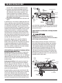
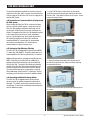
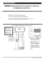
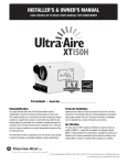
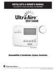
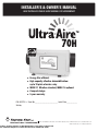
INSTALLER’S & OWNER’S MANUAL
HVAC INSTALLER: PLEASE LEAVE MANUAL FOR HOMEOWNER
Energy Star efficient
n High capacity effective dehumidification:
up to 70 pints of water a day
n MERV-11 filtration standard; MERV-14 optional
n Compact design
n 5 year warranty
n
P/N 4033730 • Serial No.________________________ Install Date:___________
Sold by:
4201 Lien Rd Madison, WI 53704 • TOLL-FREE 1-800-533-7533 • www.thermastor.com • [email protected]
© 2012 Therma-Stor LLC • Manual P/N TS-781
To Buy: Contact Sylvane at 800-834-9194 or visit www. sylvane.com
For Technical Support: Contact Therma-Stoir at 800-533-7533
TABLE OF CONTENTS
10. Service ....................................................................13
10.1 Technical Description . ...........................................13
10.2 Troubleshooting ................................................14
10.3 Refrigerant Charging . .......................................14
10.4 Compressor/Capacitor Replacement .................15
10.5 Electric Ventilation Damper ...............................15
11. DEH 3000/DEH 3000R Digital Controller...................16
Warranty .......................................................................17
Safety Precautions . .........................................................3
1. Intended Application ....................................................3
2. Registrations ...............................................................3
3. Specifications ..............................................................3
4 . Installation . ................................................................3
4.1 Installation Checklist .............................................3
4.1A Power Accessibility ........................................3
4.1B Space ............................................................4
4.1C Low Voltage Wiring . .......................................4
4.1D Back-Draft Damper . ......................................4
4.1E Support Structure and Suspension .................4
4.2 Electrical Requirements ........................................4
4.3 Condensate Removal ............................................5
4.3A Lifting Condensate .........................................5
4.3B Condensate Pump Kit . ...................................5
4.4 Ducting ................................................................5
4.4A Fresh Air/Supply Air ........................................5
4.4B Ducting for Fresh Air - Option .........................5
4.4C Installation in a Basement or Crawlspace .......6
4.4D Installation in an Attic . ...................................6
4.4E Installation in a Structure with
No Forced Air HVAC System.....................................7
4.4F Ducting for High Efficiency Filtration................7
4.4G Converting to Vertical Discharge Airflow..........7
4.5 Noise Abatement....................................................8
4.6 Controls ................................................................8
5. Control Package Diagram Sheet...................................9
6. Maintenance . ............................................................10
6.1 High Efficiency Air Filter ......................................10
6.2 Optional Fresh Air Intake .....................................10
7. Wiring Schematics..................................................... 11
8. Optional Parts List .....................................................11
9. Service Parts List . ....................................................12
Routine Maintenance.................................................12
2
Ultra-Aire 70H Installer’s & Owner’s Manual
SAFETY PRECAUTIONS
3. Specifications
Read the installation, operation and maintenance instructions
carefully before installing and operating this device. Proper
adherence to these instructions is essential to obtain
maximum benefit from your Ultra-Aire 70H indoor air quality
system.
Part Number:
Blower:
Power:
Supply Voltage:
Current Draw:
Energy Factor:
Operating Temp.:
4033730
150 CFM @ 0.0" WG
580 Watts @ 80°F and 60% RH
110-120 VAC – 1phase – 60 Hz
5.1 Amps
2.32 L/kWh
Between 49°F and 95°F Max (inlet air temp)
Sized for:
Up to 1800 Sq. Ft. - Typical
Miniumum Performance at 80°F and 60% RH
Water Removal:
70 pints/day
Efficiency:
4.9 Pints/kWh
Air Filter:
MERV-11
Efficiency:Standard 65% Efficient
ASHRAE Dust Spot Test
Size:
9" x 11" x 1"
Power Cord:
9', 110-120 VAC, Ground
Drain Connection: 3/4" Threaded NPT
Dimensions
Unit
Shipping
Width:
12"
15 5/8"
Height:
12"
16"
Depth:
28"
31 5/8"
Weight:
55 lbs
65 lbs
READ AND SAVE THESE INSTRUCTIONS
• The device is designed to be installed INDOORS IN A SPACE
THAT IS PROTECTED FROM RAIN AND FLOODING.
• Install the unit with space to access the front panel for
maintenance and service. DO NOT INSTALL UNIT WITH THE
SERVICE PANEL INACCESSIBLE.
• Avoid directing the discharge air at people, or over the
water in pool areas.
• If used near a water source; be certain there is no chance
the unit could fall into the water or get wet. The unit should
also be plugged into a GFCI (Ground Fault Circuit Interrupt
outlet).
• DO NOT use the device as a bench or table.
• DO NOT place the device directly on structural members.
• A drain pan MUST be placed under the unit if installed
above a living area or above an area where water leakage
could cause damage (see local regularity code for more
information).
Read and Save These Instructions
4. Installation
WARNING! — This symbol indicates
important instructions. Failure to heed them can result
in serious injury or death.
4.1 Installation Checklist
CAUTION
CAUTION! — This symbol indicates
important instructions. Failure to heed them can result
in injury or material property damage.
Prior to installation of the Ultra-Aire 70H, the following
checklist should be reviewed. The Ultra-Aire 70H can be
installed in a variety of locations to meet the owner’s needs,
and be integrated with existing forced air systems or existing
ductwork if desired. The location choice is contingent on
a variety of requirements not limited to: ease of service,
controls access, drainage, filtration, power, fresh-air
ventilation (optional), water damage prevention, and current
regulatory codes (ASHRAE, fire, etc). Please address all of
these issues before you select the location of the device.
1. Intended Application for Ultra-Aire 70H
For the ideal installation, draw air from the central part of
the home and return it to isolated areas of the home like the
bedrooms, den, utility room, or family room. The ductwork of the
existing heating system can be used to supply air to the home.
2. Registrations
The Ultra-Aire 70H conforms to UL STD 474 and CSA
Standard C22.2 No.92.
n4
.1A Power Accessibility
Unit should be located in an area where the cord’s length (9')
should easily reach a 110-120 VAC electrical outlet with a
minimum of a 15 A circuit capacity.
3
Ultra-Aire 70H Installer’s & Owner’s Manual
FOR HVAC INSTALLER ONLY
n4
.1B Space
4.2 Electrical Requirements
Location should have enough clearance to handle the unit’s
overall dimensions as well as the necessary return/supply
ductwork to the unit. Allow a minimum 12" clearance to the
side of the unit to allow for filter removal and replacement.
Refer to section 6.1.
WARNING!
WARNING: DO NOT ALLOW THE YELLOW LEAD FROM
THE ULTRA-AIRE TO CONTACT THE RED LEAD FROM THE
ULTRA-AIRE OR DAMAGE TO THE TRANSFORMER WILL
RESULT.
The Ultra-Aire 70H plugs into a common grounded
115VAC outlet. The device draws 5.1 Amps under normal
operating conditions. If used in an area which may become
wet, a ground fault interrupter (GFI) protected circuit is
recommended. Please, consult local electrical codes for any
further information.
n4
.1C Low Voltage Wiring
Unit location should be in an area where field wiring the
remote controls (low voltage) to the unit will be possible.
n4
.1D Back-Draft Damper (P/N 4023647 or 4023646)
It is recommended that a back draft damper be used in
the discharge duct of the Ultra-Aire 70H, especially when
connecting to the supply ducting system. The backdraft
damper prevents supply air from counter flowing through
the Ultra-Aire 70H when it is not operating. The unit location
should be chosen to allow installation of this accessory.
Therma-Stor LLC offers a family of control devices for use
with the Ultra-Aire 70H. The controls are to be located
remotely from the unit and located in the space to be
conditioned. The controls are low voltage (24 volt) and should
be connected to the Ultra-Aire 70H with low voltage wire
(thermostat or other appropriate).
n4
.1E Support Structure and Suspension
Place the Ultra-Aire 70H on supports to raise the base of the
unit. Do not place the Ultra-Aire 70H directly on structural
building members without vibration absorbers or unwanted
noise may result.
CAUTION
Do not install the control panel where it may not
accurately sense the relative humidity such as near
HVAC supply registers, near exterior doors, on an outside
wall, near a window, or near a water source.
The Ultra-Aire 70H may be suspended with a hang kit
(4029908) or a suitable alternative from structural members,
as long as the suspending assembly supports the Ultra-Aire
70H’s base in its entirety. Do not hang the Ultra-Aire 70H
from the cabinet. Remember to place a drain pan under the
The installer must supply the wiring between the Ultra-Aire
70H and the control panel. Be sure to safely route the control
wiring to prevent damage during installation.
CAUTION
Do not cross wires when connecting the Ultra-Aire 70H and
the remote control panel or damage to the transformer may
result. The remote controls of the Ultra-Aire 70H are powered
by a low voltage circuit (24VAC) and must NEVER contact or
be connected to a high voltage circuit.
The control wires leaving the Ultra-Aire 70H and the remote
control panels are numbered and color-coded to prevent
confusion. Some of the control wires leaving the Ultra-Aire
70H may not be used with certain control panels and should
be left unconnected with wire nuts taped onto the stripped
ends for safety. Be sure to consult the electrical schematic in
this manual or inside the access panel of the Ultra-Aire 70H
before making control connections.
Hang Kit (4029908) shown suspending a Ultra-Aire 70H. Available
from your dealer or Therma-Stor. Call 1-800-533-7533.
unit if it is suspended above a finished area or above an area
where water leakage could cause damage.
4
Ultra-Aire 70H Installer’s & Owner’s Manual
FOR HVAC INSTALLER ONLY
4.3 Condensate (Water) Removal
4.4 Ducting
For the ideal installation, draw air from the central part of the
home and return it to the isolated areas of the home like the
bedrooms, den, utility room, or family room. The ductwork
of the existing heating system can be used to supply air to
the home. If the existing supply goes to isolated areas of
the home, discharge the supply of the Ultra-Aire 70H into
the supply of the existing heating system. Installation of a
separate supply duct to the Ultra-Aire 70H from a central
area is recommended.
CAUTION
A trap in the drain line is preferred, but not required for
the unit to drain properly. Local codes may require a trap.
Use care to keep the pipe assembly as flat to the floor as
possible. Kinks and/or humps will prevent proper drainage.
The Ultra-Aire 70H generates condensate. Install a 3/4" male
nominal pipe thread adapter to the drain pan. It is necessary
to assemble your own drain pipe assembly utilizing 3/4"
PVC pipe to get the condensate to a floor or other drain. Pipe
is commonly available in 10’ lengths from building supply,
plumbing or hardware stores. Grade of pitch should be 1"
per 10'.
4.4A Supply Air
CAUTION
DO NOT draw air directly from the kitchen, laundry, or
isolated basement.
4.3A Lifting Condensate
A condensate pump may installed if lift is required to dispose
of the condensate.
You may draw air from a basement that is open to the home.
All flexible ducting connected to the Ultra-Aire 70H should be
UL listed.
4.3B Condensate Pump Kit (4030113)
A condensate pump kit is available from the factory for use
with the Ultra-Aire 70H and provides 15' of lift. Condensate is
automatically pumped to a remote location when the water
level in the pump’s reservoir rises to close the float switch.
The pump also contains a safety float switch. The white leads
from this switch extend from beneath the pump cover. This
switch should be installed in series with the field wire that
connects the blue (#5) lead from the Ultra-Aire 70H to the
the control panel. If the pump fails, this switch opens the
compressor control circuit and stops water production before
the reservoir overflows. The Ultra-Aire 70H will continue to
ventilate or circulate air as normal, but will not dehumidify
until this switch closes.
A short piece of flexible ducting on all Ultra-Aire 70H duct
connections is recommended to reduce noise and vibration
transmitted to rigid ductwork in the structure. Ducting the
Ultra-Aire 70H as mentioned requires consideration of the
following points:
Duct Sizing: For total duct lengths up to 25', use a minimum
8" diameter round or equivalent rectangular. For longer
lengths, use a minimum 10" diameter or equivalent. Grills
or diffusers on the duct ends must not excessively restrict
airflow.
Connecting to existing HVAC systems: An optional 8"
check backdraft damper is available from the factory to
prevent reverse air flow through the Ultra-Aire 70H. If the
Ultra-Aire 70H is ducted to the supply of an air handler, the
check damper should be placed in the Ultra-Aire 70H supply
duct.
CAUTION
Contact the factory when connecting to a static pressure
of greater than or equal to +.5" WG.
4.4B Ducting for Fresh Air — Option
Fresh air may be brought into the structure by connecting an
insulated duct from outside the structure to a tee located in
the inlet duct of the Ultra-Aire 70H. Advantages of this form
of ventilation include:
Condensate Pump Kit (4030113) shown installed. Available from
your dealer or Therma-Stor. Call 1-800-533-7533.
1. Outside air is filtered before entering the building.
2. Outside air will be dehumidified before entering if the
5
Ultra-Aire 70H Installer’s & Owner’s Manual
FOR HVAC INSTALLER ONLY
Ultra-Aire 70H is running in dehumidification mode.
3. Drawing air from outside and blowing inside aids in
slightly pressurizing the structure. This helps prevent
dirty and humid air from entering elsewhere. It also
reduces the potential for carcinogenic radon gas to
enter and provides a small amount of make-up air for
open combustion and exhaust devices like the clothes
drier, fireplace, and water heater.
4. Exhaust fans are recommended in the bath rooms and
kitchen.
Ultra-Aire
Indoor Air
Return
Heating/AC Return Air
DEH 3000
control
Backdraft
Damper
Optional
Fresh Air
Intake
In cold climates or areas where the outdoor dew point is low
at times, ventilation can be used to dehumidify the structure,
making the Ultra-Aire 70H capable of year-round drying. This
is accomplished by bringing the dry, low dew point air into
the structure during these times. This approach is often more
economical than running the dehumidifier to remove excess
moisture from the structure. In cold climates, adequately
ventilating is critical to reduce the inside moisture content
and avoid moisture accumulating in the wall cavities. TIP: if
your house experiences condensation on the interior surface
of the windows during the winter, increasing the amount of
ventilation will often solve the problem.
Dry Air to
Basement
Motorized
Damper
Gravity
Damper
use a return from a room that may have its door closed much
of the time or, alternatively, install a separate return from the
open part of the house.
4.4D Installation in an Attic with an Existing Forced Air
HVAC System
CAUTION
ALWAYS place a drain pan under the unit if it is
suspended above a finished area or above an area where
water leakage could cause damage.
An insulated 6" diameter duct is generally sufficient to
provide up to 55 CFM of outside air. Large quantities of
outside air will impact Ultra-Aire 70H performance positively
or negatively, depending upon the inside and outside air
conditions. The outside air duct should be connected to the
front of the unit. With a standard tee, the amount of outside
air can be restricted with a blade damper.
When installing the Ultra-Aire 70H above a finished area or
where water leakage could cause damage, use a secondary
drain pan with an overflow interrupter switch. The interrupt
switch should be installed in series with the field wire that
connects the blue (#5) lead from the Ultra-Aire 70H to the
blue (#5) lead on the control panel. If overflow occurs, this
switch opens the compressor control circuit and stops water
production before the drain pan overflows. The Ultra-Aire 70H
will continue to ventilate or circulate air as normal, but will not
dehumidify until this switch closes.
4.4C Installation in a Basement or Crawlspace with an
Existing Forced Air HVAC System.
Basement Installation: Install a separate 8" return for the
Ultra-Aire 70H in a central area of the structure. Optional:
Duct the supply of the Ultra-Aire to a 8" x 8" x 8" tee/damper,
adjusted to 20% open to the basement. Duct the other side
of the tee to the air supply of the existing HVAC system with a
backdraft damper.
Optional
Fresh Air
Intake
Crawlspace Installation: Install a separate return for the
Ultra-Aire 70H in a central area of the structure. Optional:
Duct the supply of the Ultra-Aire 70H to a 8" x 8" x 8" tee/
damper that is 20% open to the crawlspace if desired. Duct
the other side of the tee to the air supply of the existing HVAC
system with a backdraft damper.
Heating & A/C Unit
Ultra-Aire
Air Supply
Backdraft
Damper
Indoor Air
Return
Motorized
Damper
Instead of installing a separate return to the Ultra-Aire 70H,
and if the existing system has multiple returns, it is possible
to select one to disconnect from the existing forced air
system and use it for the dedicated Ultra-Aire return. Always
select a return from a central location in the structure in an
area that is always open to the rest of the structure. Do not
Ultra-Aire
Indoor Air Return
Indoor Air Supply
DEH 3000
control
6
Ultra-Aire 70H Installer’s & Owner’s Manual
FOR HVAC INSTALLER ONLY
The preferred method of installation is to create a separate
return for the Ultra-Aire 70H in a central area of the structure.
Duct the supply of the Ultra-Aire 70H to the air supply of the
existing HVAC system.
1. Using T-20 Torx Driver, remove three (3) sheet metal
screws that attach the exhaust panel from each side of the
Ultra-Aire 70H. There will be a total of six (6) screws. Do not
remove the exhaust collar.
4.4E Installation in a Structure with No Existing Forced
Air HVAC System
When installing the Ultra-Aire 70H in a structure that does
not have a forced air HVAC system, a single return for the
Ultra-Aire 70H should be installed in central open area of
the structure. DO NOT locate the return in a bathroom or a
kitchen. The supplies of the Ultra-Aire 70H should be located
in the remote areas of the structure (such as bedrooms,
den, etc.). By ducting this way, the air inside the structure
will circulate through the Ultra-Aire 70H to be filtered
and dehumidified. A 6" diameter duct is recommended
for branches to the bedrooms. A 8" diameter duct is
recommended for branches to larger areas.
2. Remove the exhaust panel.
4.4F Ducting for High Efficiency Filtration
The Ultra-Aire 70H is equipped with a high efficiency MERV
11 media filter (P/N 4030671). For optimal performance it is
recommended that the filter be replaced every 3-6 months.
Additional filtering options, including charcoal filtration and
MERV 14 filtration, are available with the addition of an
optional external filter housing that may be installed with
the Ultra-Aire 70H. The external filter housing is ducted to
the inlet of the Ultra-Aire 70H and intake ducting from the
structure is ducted to the intake side of the filter housing.
The external filter housing can accommodate a variety of
filter combinations up to a total of 6” in thickness. Contact
the factory or visit www.ultra-aire.com for additional details.
3. Rotate the exhaust panel so that the exhaust collar is
located on the top of the unit. Align screw holes and snap
the panel onto the base.
4.4G Converting to Vertical Discharge Airflow
The Ultra-Aire 70H is shipped from the factory with the
exhaust panel of the cabinet configured for horizontal air
discharge. The cabinet can be easily converted to vertical
air discharge. To convert the air discharge from horizontal to
vertical, follow these steps:
4. Secure the exhaust panel to the base by replacing the six
(6) screws.
7
Ultra-Aire 70H Installer’s & Owner’s Manual
4.5 Noise Abatement
A length of 10 feet or more of flex ducting on the outlet of
the Ultra-Aire 70H will reduce air noise from the fan. A length
of flexible ducting on all Ultra-Aire 70H duct connections is
recommended to reduce noise transmitted to rigid ductwork
in the structure.
The Ultra-Aire dehumidifier is controlled using five
color-coded wires.
Green (or brown) = Fan control
Blue = Dehumidification (fan and compressor) control
4.6 Controls
The Ultra-Aire 70H features a built-in dehumidistat control
as well as the ability to wire a remote mounted control to the
unit. The control used to operate the unit should be located in
an area where the control can accurately sense the humidity
of the area where humidity control is desired.
Red = 24volt AC power transformer neutral side (common
with white)
If the Ultra-Aire 70H is located in the area where humidity
control is desired, consider using the built-in control. Adjust
the humidity control so that the unit maintains the desired
level of humidity.
Between the red/white lead and the yellow leads is a 40VA
transformer. This low voltage power source powers the relay
coils which control the fan and compressors. This 24VAC
transformer can also be used to power HVAC assessories
external to the dehumidifier.
White = 24volt AC power transformer neutral side (common
with red)
Yellow = transformer high side
If the Ultra-Aire 70H is located outside of the area where
humidity control is desired, consider using a remote wired
humidity controller that is located in the area where humidity
control is desired.
When using a remote wired dehumidistat, be sure the
built-in dehumidistat is set to the off position by turning it
counterclokwise until it stops. Failure to do so may cause the
unit to sense the humidity from the wrong area.
•
To turn the dehumidifier on make contact between yellow
and blue wires.
•
To turn the fan on make contact between yellow and green
(or brown) wires.
•
To power an HVAC accessory, connect the accessory to
the white (or red) wire and the yellow wire.
WARNING: DO NOT allow the yellow lead from the
unit to contact the red lead or the white lead from the
unit or damage to the transformers will result.
(P/N 4028539; with remote: P/N 4028407)
8
Ultra-Aire 70H Installer’s & Owner’s Manual
ATTENTION INSTALLER
WARNING: Allowing yellow wire to contact red or white wire
will destroy the transformer.
Dehumidifier on : Connect yellow and blue wires.
Fan only on : Connect yellow and green (or brown) wires.
Accessory power : 24volt AC power supply available for HVAC accessories between yellow and
white(and/or red) wire. Red and white wires are common with each other.
Ultra-Aire DEH3000 Dehumidification & Ventilation Control
Warning: if the optional
damper is not used,
DO NOT connect the
white wire to the control
or damage to the
transformer may result.
GREEN or BROWN
BLUE
RED
YELLOW
WHITE
Ultra-Aire
Dehumidifier
OPTIONAL
DAMPER
24 VAC
Control Part No. 4028539
Internal Connections
DMP COMP FAN
Refer to DEH3000 manual for
additional wiring diagrams.
DEH3000R (with remote wired
sensor) is also available as
a separate unit. Refer to the
DEH3000R manual for wiring
details.
4201 Lien Rd. Madison, WI 53704 • TOLL-FREE 1-800-533-7533 • www.thermastor.com • [email protected]
TS-234, 11/09
9
Ultra-Aire 70H Installer’s & Owner’s Manual
FOR HVAC INSTALLER AND HOMEOWNER
6. Maintenance
6.2 Optional Fresh Air Intake
Check and clean the screen on the outdoor fresh air intake
port seasonally. The screen may become plugged during the
seasons when there are many particles in the outdoor air.
6.1 High Efficiency Air Filter
The Ultra-Aire 70H is equipped with a MERV 11 media filter.
This filter should be checked every three months. Operating
the unit with a dirty filter will reduce dehumidifier capacity
and efficiency and may cause the compressor to cycle off
and on unnecessarily on the defrost control.
Notes:
DO NOT operate the unit without a filter or with a less
effective filter. Operating the unit without a filter or with
a less effective filter may cause internal damage to the
unit and invalidate the product warranty.
To replace the filter, remove the filter door from one of the
sides of the Ultra-Aire 70H by pushing the snap button in
and gently pulling to door away from the body of the unit,
then pulling up to disengage the door flange from the slot,
removing the door.
Remove the filter by gently pulling straight out of the unit.
Insert new filter in the same manner, pushing it gently
straight into the unit.
Replace filter door by inserting the bottom tab into the slot,
aligning the door and pushing it gently against the unit until
the snap button secures the door.
10
Ultra-Aire 70H Installer’s & Owner’s Manual
Ultra-Aire 70H WIRING SCHEMATIC
7. Wiring Schematic
8. Optional Parts List: Ultra-Aire 70H Indoor Air Quality System
Part No.
4030671
4030113
4029908
4023647
4020646
4027415
4020177
Description
Filter MERV 11
Pump Kit
Hang Kit
8" Gravity Damper
8" Butterfly Damper
8" Flex Duct
8" Flex Duct (insulated)
11
Ultra-Aire 70H Installer’s & Owner’s Manual
FOR HVAC INSTALLER ONLY
9. Service Parts List: Ultra-Aire 70H Indoor Air Quality System
Part No.
4029567
4029568
4022484
4033032-03
4033358-02
4031384
4020924
4033031-03
4031376
4022487
4026221
4027172
Description
Compressor
Compressor Overload
Compressor Relay
Run Capacitor
Coil Set
Impeller Fan
Fan Relay
Fan Capacitor
Defrost Thermostat
Transformer
Leveling Foot
Humidity Control
FOR HOMEOWNER - ROUTINE MAINTENANCE
Part No.
4030671
4030734
4030733
Description
Air Filter MERV 11
4 Pack
12 Pack
The Ultra-Aire 70H is equipped with a MERV 11 media filter. This filter should
be checked every three months. Operating the unit with a dirty filter will reduce
dehumidifier capacity and efficiency and may cause the compressor to cycle
off and on unnecessarily on the defrost control. Refer to section 6.1 for filter
replacement instructions.
12
Ultra-Aire 70H Installer’s & Owner’s Manual
FOR HVAC INSTALLER ONLY
10. Service
CAUTION
CAUTION: Servicing the Ultra-Aire 70H with its high
pressure refrigerant system and high voltage circuitry
presents a health hazard which could result in death,
serious bodily injury, and/or property damage. Please
contact your HVAC professional.
10.1 Technical Description
The Ultra-Aire 70H uses a refrigeration system similar to an
air conditioner’s to remove heat and moisture from incoming
air, and add heat to the air that is discharged. Hot, highpressure refrigerant gas is routed from the compressor to
the condenser coil (See Figure 1). The refrigerant is cooled
and condensed by giving up its heat to the air that is about
to be discharged from the unit. The refrigerant liquid then
passes through a strainer and capillary tubing which causes
the refrigerant pressure and temperature to drop. It next
enters the evaporator coil where it absorbs heat from the
incoming air and evaporates. The evaporator operates in a
flooded condition, which means that all the evaporator tubes
contain liquid refrigerant during normal operation. A flooded
evaporator should maintain nearly constant pressure and
Refrigeration System of Ultra-Aire 70H
temperature across the entire coil, from inlet to outlet.
The mixture of gas and liquid refrigerant enter the
accumulator after leaving the evaporator coil. The
accumulator prevents any liquid refrigerant from reaching the
compressor. The compressor evacuates the cool refrigerant
gas from the accumulator and compresses it to a high
pressure and temperature
13
Ultra-Aire 70H Installer’s & Owner’s Manual
No ventilation. Ventilation is being called for.
1. Loose connection in ventilation control circuit
2. Loose connection in damper power circuit.
3. Defective fresh air damper.
10.2 Troubleshooting
Unit doesn’t respond to humidity setpoint on remote
wired dehumidistat.
1. Verify built-in dehumidistat is turned to the “off”
position.
2. Check calibration of the control to determine if it is
reading humidity level properly.
3. Verify control wiring is intact by connecting control
directly to the pigtail of the unit.
Unit removes some water, but not as much as expected.
1. Air temperature and/or humidity have dropped.
2. Humidity meter and or thermometer used are
out of calibration.
3. Unit has entered defrost cycle.
4. Air filter dirty.
5. Defective defrost thermostat.
6. Low refrigerant charge.
7. Air leak such as loose cover or ducting leaks.
8. Defective compressor.
9. Restrictive ducting.
10.Optional Condensate Pump Safety Switch open.
Neither fan nor compressor running. Dehumidification is
being called for. No fan call.
1. Unit unplugged or no power to outlet.
2. Humidity control set too high.
3. Loose connection in internal or control wiring.
4. Defective Compressor relay.
5. Defective control transformer.
Unit Test to determine problem:
1. Detach field control wiring connections from main unit.
2. Connect the yellow and green pigtails from the main
unit together; only the fan should run. Disconnect the
wires.
3. Connect the yellow and blue pigtails from the main unit
together or turn the built-in dehumidistat all the way
clockwise to the "on" position; the compressor and fan
should run.
4. If these tests work, the main unit is working properly.
You should check the control panel and field control
wiring for problems next.
5. Remove the control panel from the mounting box and
detach it from the field installed control wiring. Connect
the blue, yellow, and green wires from the control
panel directly to the corresponding colored pigtails on
the main unit. Leave the green, white and red wires
disconnected!
6. Engage the fan switch on the control; the fan should
run. Turn off the fan switch.
7. Engage the dehumidistat of the control; the compressor
and fan should run.
8. If these tests work, the problem is most likely in the
field control wiring.
Compressor is not running. Dehumidification is being
called for. No fan call.
1. Defective compressor run capacitor.
2. Loose connection in compressor circuit.
3. Defective compressor overload.
4. Defective compressor.
5. Defrost thermostat open.
Compressor cycles on and off. Dehumidification is being
called for. No fan call
1.Low ambient temperature and/or humidity causing unit
to cycle through defrost mode.
2. Defective compressor overload.
3. Defective compressor.
4. Defrost thermostat defective.
5. Dirty air filter(s) or air flow restricted.
Fan is not running. Dehumidification or fan is being
called for
1. Loose connection in fan circuit.
2. Obstruction prevents fan impeller rotation.
3. Defective fan.
4. Defective fan relay.
10.3 Refrigerant Charging
If the refrigerant charge is lost due to service or a leak, a
new charge must be accurately weighed in. If any of the
old charge is left in the system, it must be recovered before
weighing in the new charge. Refer to the unit nameplate for
the correct charge weight and refrigerant type.
Low dehumidification capacity (evaporator is frosted
continuously). Dehumidification is being called for
1.
2.
3.
4.
Defrost thermostat loose or defective.
Low refrigerant charge
Dirty air filter(s) or air flow restricted.
Excessively restrictive ducting connected to unit.
14
Ultra-Aire 70H Installer’s & Owner’s Manual
FOR HVAC INSTALLER ONLY
10.4 Compressor/Capacitor Replacement
This compressor is equipped with a two terminal external
overload and a run capacitor, but no start capacitor or relay.
CAUTION
CAUTION-ELECTRICAL SHOCK HAZARD: Electrical power
must be present to perform some tests. These tests
should be performed by a qualified service person.
10.5 Electric Ventilation Damper
The damper will open when the ventilation is called for,
allowing fresh air into the structure through the fresh air
inlet duct. The electric ventilation damper will remain closed
when the ventilation is not activated in order to prevent overventilating the structure when the unit is dehumidifying or
recirculating the indoor air. The electric ventilation damper
operates on 24 Vac from the control circuit. DO NOT connect
high voltage to the damper motor or damage to the motor
will result. DO NOT force the blade of the damper by hand or
damage to the damper motor may result.
The damper opens in one direction only. The damper rotates
very slowly, allow sufficient time for the damper to cycle. The
damper will take approximately one minute to cycle from
closed to open or from open to closed.
If the electric ventilation damper fails to operate:
1. Check that the wiring is correct and that voltage is
present at the damper motor.
2. Check for any obstruction inside the damper. If the
electric ventilation damper fails to operate after
performing these checks, it must be replaced.
15
Ultra-Aire 70H Installer’s & Owner’s Manual
DEH 3000/DEH 3000R
DEH 3000, DEH 3000R DEHUMIDIFIER & VENTILATION SYSTEM CONTROLLER
DEH 3000/DEH 3000R
Part No. 4028539
Part No. 4028407
11. Optional Dehumidifier & Ventilation
System Controller
Major Operations
When used with Ultra-Aire Whole House Ventilating
Dehumidifiers, the DEH 3000/3000R allows homeowners the
ability to monitor and control relative humidity levels in their
home.
n
Digital control of Relative Humidity (Digital Set-Point)
n
Fan/Filter Operation
n
Programmable Ventilation Timer
n
Large, easy-to-read backlit LCD display
DEH3000 P/N:
4028539
n
DEH3000R (remote) P/N:
Easy interaction with air handler fan (Interlock/Lockout)
4028407
n
High Temperature Cut-Out
n
Dryout Cycle Timer
n
Auto Reboot
n
Remote Sensor (DEH 3000R Only)
Model: DEH 3000
DEH 3000R (remote)
Operating Voltage:
24 VAC
Max Current
DMP, COMP, FAN:
1 AMP each
Humidity Sensing
Range/Accuracy:
10 - 95% RH, ± 5%
Humidity Setpoint Range:
35 - 70%
Auxillary Relay Capacity:
5 Amps, 24VAC
Temp Range/Accuracy:
30°-90°F, 2%
Size:
4.95"L x 1.06"W x 4.19"H
To order call Therma-Stor at
1-800-533-7533
16
Ultra-Aire 70H Installer’s & Owner’s Manual
Limited Warranty
Limited Warranty. Therma-Stor, LLC (“Therma-Stor”) warrants as
follows: (i) the Ultra-Aire 70H dehumidifier (“Product”) will be free
of material defects in workmanship or materials for a period of one
(1) year (“One-Year Warranty”) following the date of initial purchase
of such Product by an original customer purchasing from ThermaStor or an authorized reseller (“Customer”); and (ii) the Product’s
condenser, evaporator, and compressor will be free of material defects
in workmanship or materials for a period of five (5) years following the
date of initial purchase of such Product by a Customer.
Customer Responsibilities. As a further condition to obtaining
warranty coverage hereunder, the Customer must send a valid
warranty claim to Therma-Stor such that Therma-Stor receives
such claim prior to the end of the applicable warranty period.
Therma-Stor shall have no obligation hereunder with respect to
any claim received by Therma-Stor after the expiration of the
applicable warranty period. As a further condition to obtaining
warranty coverage hereunder, the Customer must present forms of
invoices evidencing proof of purchase of a Product. If such invoices
do not clearly indicate the date of initial purchase by a Customer,
the applicable Product’s date of manufacture will be used instead
of the date of initial purchase for the purpose of calculating the
commencement of the applicable warranty period. Warranty service
must be performed by Therma-Stor or a servicer authorized by
Therma-Stor. In order to obtain warranty service, the Customer
should call Therma-Stor at 1-800-533-7533 and ask for the
Therma-Stor Products Service Department, which will then arrange
for applicable warranty service. Warranty service will be performed
during customary, daytime working hours. If the Product must be
shipped for service, Customer shall be solely responsible for properly
packaging the Product, for all freight charges, and for all risk of loss
associated with shipment.
Limitation of Remedies. CUSTOMER’S SOLE AND EXCLUSIVE
REMEDY UNDER THE ABOVE LIMITED WARRANTY AND THERMASTOR’S ENTIRE LIABILITY THEREUNDER, SHALL BE, AT THE SOLE
OPTION OF THERMA-STOR, REPLACEMENT OR REPAIR OF SUCH
PRODUCT OR ITS COMPONENTS (“COMPONENTS”) BY THERMA-STOR
OR THERMA-STOR’S AGENTS ONLY. REFRIGERANT, PIPING, SUPPLIES,
TRANSPORTATION COSTS, LABOR COSTS INCURRED IN REPAIR OR
REPLACEMENT OF SUCH COMPONENTS ARE NOT INCLUDED. THIS
DISCLAIMER AND EXCLUSION SHALL APPLY EVEN IF THE EXPRESS
WARRANTY AND LIMITED REMEDY SET FORTH HEREIN FAILS OF
ITS ESSENTIAL PURPOSE. CUSTOMER ACKNOWLEDGES THAT NO
REPRESENTATIVE OF THERMA-STOR OR OF ITS AFFILIATES OR
RESELLERS IS AUTHORIZED TO MAKE ANY REPRESENTATION OR
WARRANTY ON BEHALF OF THERMA-STOR OR ANY OF ITS AFFILIATES
OR RESELLERS THAT IS NOT IN THIS AGREEMENT. Notwithstanding
the above, during the term of the One-Year Warranty only, ThermaStor will provide, free of charge to Customer, all Components and labor
(except costs related to removal and installation of Product) required to
fulfill its obligations under such One-Year Warranty.
Limitation of Liability. IN NO EVENT SHALL THERMA-STOR,
IN CONNECTION WITH THE DESIGN, SALE, INSTALLATION, USE,
REPAIR, REPLACEMENT OR PERFORMANCE OF ANY PRODUCT,
COMPONENT, PART THEREOF OR WRITTEN MATERIAL PROVIDED
THEREWITH, BE LIABLE, TO THE EXTENT ALLOWED UNDER
APPLICABLE LAW, UNDER ANY LEGAL THEORY FOR ANY SPECIAL,
DIRECT, INDIRECT, COLLATERAL OR CONSEQUENTIAL DAMAGES
OF ANY KIND. NOTWITHSTANDING THE ABOVE LIMITATIONS AND
WARRANTIES, THE SOLE AND EXCLUSIVE LIABILITY OF THERMASTOR, REGARDLESS OF THE NATURE OR THEORY OF THE CLAIM,
SHALL UNDER NO CIRCUMSTANCES EXCEED THE PURCHASE PRICE
OF THE PRODUCT, COMPONENT OR PART UPON WHICH THE CLAIM
IS PREMISED.
Disclaimer of Warranties. EXCEPT FOR ABOVE LIMITED
WARRANTY, WHICH IS THE SOLE AND EXCLUSIVE WARRANTY
PROVIDED WITH RESPECT TO THE PRODUCT AND ITS COMPONENTS,
THERMA-STOR HEREBY DISCLAIMS ALL EXPRESS AND IMPLIED
WARRANTIES, INCLUDING, WITHOUT LIMITATION, THE IMPLIED
WARRANTIES OF MERCHANTABILITY AND FITNESS FOR A
PARTICULAR PURPOSE.
Applicable Law and Venue. ANY ARBITRATION, ENFORCEMENT
OF AN ARBITRATION OR LITIGATION RELATED TO THE PRODUCT
WILL BE BROUGHT EXCLUSIVELY IN DANE COUNTY, WISCONSIN,
AND CUSTOMER CONSENTS TO THE JURISDICTION OF THE
FEDERAL AND STATE COURTS LOCATED THEREIN, SUBMITS TO
THE JURISDICTION THEREOF AND WAIVES THE RIGHT TO CHANGE
VENUE. CUSTOMER FURTHER CONSENTS TO THE EXERCISE OF
PERSONAL JURISDICTION BY ANY SUCH COURT WITH RESPECT TO
ANY SUCH PROCEEDING.
Warranty Limitations. The foregoing limited warranty extends only
to a Customer and shall be null and void upon attempted assignment
or transfer. A “defect” under the terms of the limited warranty shall
not include problems resulting from Customer’s or Customer’s
employees’, agents’, invitees’ or a third party’s misuse, improper
installation, improper design of any system in which the Product
is included, abuse, lack of normal care, failure to follow written
instructions, tampering, improper repair, or freezing, corrosion, acts
of nature or other causes not arising out of defects in Therma-Stor’s
workmanship or material. If a Product or Component is replaced
while under warranty, the applicable limited warranty period shall
not be extended beyond the original warranty time period. The
limited warranty does not cover any costs related to changes to a
Product or Component that may be required by any codes, laws, or
regulations that may become effective after initial purchase of the
Product by Customer.
Miscellaneous. If any term or condition of this Limited Warranty
is found by a court of competent jurisdiction to be invalid, illegal or
otherwise unenforceable, the same shall not affect the other terms
or conditions hereof or thereof or the whole of this Limited Warranty.
Any delay or failure by Therma-Stor to exercise any right or remedy
will not constitute a waiver of Therma-Stor to thereafter enforce
such rights.
17
Ultra-Aire 70H Installer’s & Owner’s Manual