1
OC294-D-1.qxp
05.3.9 11:01 AM
Page 1
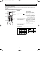
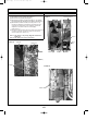
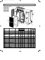
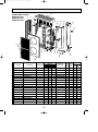
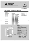
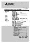
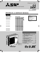
SPLIT-TYPE, HEAT PUMP AIR CONDITIONERS
2004
No.OC294
REVISED-EDITION-D
TECHNICAL & SERVICE MANUAL
R410A
Outdoor unit
[model names]
PUHZ-RP1.6VHA
PUHZ-RP2VHA
PUHZ-RP2.5VHA
PUHZ-RP3VHA
PUHZ-RP4VHA
PUHZ-RP5VHA
PUHZ-RP6VHA
PUHZ-RP4YHA
PUHZ-RP5YHA
PUHZ-RP6YHA
[Service Ref.]
PUHZ-RP1.6VHA
PUHZ-RP2VHA
PUHZ-RP2.5VHA
PUHZ-RP2.5VHA1
PUHZ-RP3VHA
PUHZ-RP3VHA1
PUHZ-RP4VHA
PUHZ-RP4VHA1
PUHZ-RP5VHA
PUHZ-RP5VHA1
PUHZ-RP6VHA
PUHZ-RP6VHA1
PUHZ-RP4YHA
PUHZ-RP5YHA
PUHZ-RP6YHA
Revision:
• PUHZ-RP4YHA,
PUHZ-RP5YHA,
PUHZ-RP6YHA are added in
REVISED EDITION-D.
• Some descriptions have
been modified.
• Please void OC294 REVISED
EDITION-C.
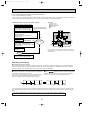
CONTENTS
Model name
indication
PUHZ-RP2.5VHA
PUHZ-RP3VHA
1. TECHNICAL CHANGES·································2
2. SAFETY PRECAUTION··································3
3. COMBINATION OF INDOOR AND OUTDOOR UNITS···7
4. PART NAMES AND FUNCTIONS ··················7
5. SPECIFICATIONS···········································8
6. DATA ·····························································12
7. OUTLINES AND DIMENSIONS····················14
8. WIRING DIAGRAM ·······································17
9. WIRING SPECIFICATIONS ··························20
10. REFRIGERANT SYSTEM DIAGRAM··············22
11. TROUBLESHOOTING···································28
12. DISASSEMBLY PROCEDURE ·····················81
13. PARTS LIST ················································108
14. OPTIONAL PARTS························Back Cover
OC294-D-1.qxp
1
05.3.9 11:01 AM
Page 2
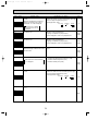
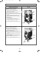
TECHNICAL CHANGES
PUHZ-RP4VHA ➞ PUHZ-RP4VHA1
PUHZ-RP5VHA ➞ PUHZ-RP5VHA1
PUHZ-RP6VHA ➞ PUHZ-RP6VHA1
1. Reduced Design Pressure:
Design Pressure has been changed from 4.41MPa to 4.15MPa.
(High Pressure Switch has been changed.)
2. Partial Change on Refrigerant Circuit:
Only 1 distributor is adopted on the Heat Exchanger. (Previously 2)
3. Partial Change on Electrical Wiring:
Change of reactor (DCL).
Only 1 reactor (DCL) is adopted. (Previously 2)
4. New Service Parts as a result of the structural improvement:
• Power Receiver
• Separator
• Rubber Mount (for a Compressor)
• Thermistor (2 phase pipe, Outdoor temperature)
• Thermistor (Discharge)
• Linear Expansion Valve Coil
5. Reduced Refrigerant Amount
The Charged Refrigerant Amount has been reduced from 5.5kg to 5.0kg
6. Wider Operation Range:
A change is made on the Minimum Capacity.
(For details, please refer to the Service Manual for indoor units.)
PUHZ-RP2.5VHA ➞ PUHZ-RP2.5VHA1
PUHZ-RP3VHA ➞ PUHZ-RP3VHA1
1. The parts below have been changed.
• Thermistor (Outdoor pipe / TH3)
• Linear expansion valve coil
2. The refrigerant circuit has been changed.
• High pressure switch (4.41MPa ➞ 4.14MPa)
• Charge plug
2
OC294-D-1.qxp
05.3.9 11:01 AM
2
Page 3
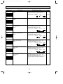
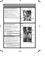
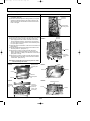
SAFETY PRECAUTION
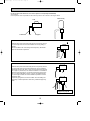
2-1. CAUTIONS RELATED TO NEW REFRIGERANT
Cautions for units utilizing refrigerant R410A
Use new refrigerant pipes.
Do not use refrigerant other than R410A.
In case of using the existing pipes for R22, be careful with
the followings.
· For RP4, 5 and 6, be sure to perform replacement operation before test run.
· Change flare nut to the one provided with this product.
Use a newly flared pipe.
· Avoid using thin pipes.
If other refrigerant (R22 etc.) is used, chlorine in refrigerant can cause deterioration of refrigerant oil etc.
Make sure that the inside and outside of refrigerant piping is clean and it has no contamination
such as sulfur hazardous for use, oxides, dirt,
shaving particles, etc.
In addition, use pipes with specified thickness.
Contamination inside refrigerant piping can cause deterioration of refrigerant oil etc.
Use a vacuum pump with a reverse flow check
valve.
Vacuum pump oil may flow back into refrigerant cycle and
that can cause deterioration of refrigerant oil etc.
Use the following tools specifically designed for
use with R410A refrigerant.
The following tools are necessary to use R410A refrigerant.
Gauge manifold
Charge hose
Gas leak detector
Torque wrench
Tools for R410A
Flare tool
Size adjustment gauge
Vacuum pump adaptor
Electronic refrigerant
charging scale
Store the piping to be used during installation
indoors and keep both ends of the piping sealed
until just before brazing. (Leave elbow joints, etc.
in their packaging.)
Keep the tools with care.
If dirt, dust or moisture enter into refrigerant cycle, that can
cause deterioration of refrigerant oil or malfunction of compressor.
If dirt, dust or moisture enter into refrigerant cycle, that can
cause deterioration of refrigerant oil or malfunction of compressor.
Use ester oil, ether oil or alkylbenzene oil (small
amount) as the refrigerant oil applied to flares
and flange connections.
If large amount of mineral oil enter, that can cause deterioration of refrigerant oil etc.
Do not use a charging cylinder.
If a charging cylinder is used, the composition of refrigerant will change and the efficiency will be lowered.
Ventilate the room if refrigerant leaks during
operation. If refrigerant comes into contact with
a flame, poisonous gases will be released.
Charge refrigerant from liquid phase of gas
cylinder.
If the refrigerant is charged from gas phase, composition
change may occur in refrigerant and the efficiency will be
lowered.
[1] Cautions for service
(1) Perform service after collecting the refrigerant left in unit completely.
(2) Do not release refrigerant in the air.
(3) After completing service, charge the cycle with specified amount of refrigerant.
(4) When performing service, install a filter drier simultaneously.
Be sure to use a filter drier for new refrigerant.
[2] Additional refrigerant charge
When charging directly from cylinder
· Check that cylinder for R410A on the market is syphon type.
· Charging should be performed with the cylinder of syphon stood vertically. (Refrigerant is charged from liquid phase.)
3
OC294-D-1.qxp
05.3.9 11:01 AM
Page 4
Unit
Gravimeter
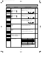
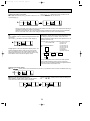
[3] Service tools
Use the below service tools as exclusive tools for R410A refrigerant.
No.
1
Specifications
Gauge manifold
·Only for R410A
·Use the existing fitting specifications. (UNF1/2)
·Use high-tension side pressure of 5.3MPa·G or over.
2
Charge hose
3
Electronic scale
4
Gas leak detector
·Use the detector for R134a, R407C or R410A.
·Attach on vacuum pump.
·Only for R410A
·Use pressure performance of 5.09MPa·G or over.
5
Adaptor for reverse flow check
6
Refrigerant charge base
7
Refrigerant cylinder
·Only for R410A
Top of cylinder (Pink)
Cylinder with syphon
8
Refrigerant recovery equipment
4
OC294-D-1.qxp
05.3.9 11:01 AM
Page 5
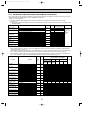
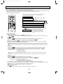
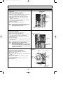
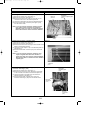
2-2. CHANGED POINT
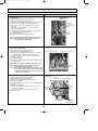
• Precautions when reusing existing R22 refrigerant pipes
(1) Flowchart
Measure the existing pipe thickness and check for damage.
The existing pipe thickness meets specifications and the pipes are not damaged.
The existing pipe thickness does not meet
specifications or the pipes are damaged.
Check if existing air conditioner can operate.
Existing air conditioner can
operate.
Existing air conditioner
cannot operate.
Perform cooling operation
for about 30 minutes and
then do a pump down work.
Use a refrigerant recovery
equipment to collect the refrigerant.
Check the oil condition
when collecting the refrigerant.
Oil is clean.
Oil is dirty.
When the compressor bearings
are glazed, rotation scratches
are present, or the compressor
breaks down, iron particles or
oil deterioration will blacken the
oil.
Disconnect existing air conditioner
from pipes and clean pipes using
cleaning device.
Disconnect existing air conditioner from piping.
Attach a filter drier.
Existing pipes can be reused.
Existing pipes cannot be
reused. Use new pipes.
In case the unit is RP1.6, 2,
2.5 ro 3 which utilizes AB oil.
In case the unit is RP4, 5
or 6 which utilize ester oil.
Connect a new air conditioner.
Connect a new air conditioner.
Perform replacement operation.
·When performing replacement operation, make sure that DIP SW8-2 on outdoor unit controller board is
set to ON.
wChemical compounds containing chlorine left in existing pipes are collected by replace filter.
●The air conditioner automatically performs cooling operation through replace filter for about 2 hours.
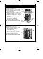
Connecting a new air conditioner
1Flaring work should be done so that flare meets the dimension for R410A.
Use flare nut provided with indoor and outdoor unit.
2When using gas piping of [19.05mm for RP4, 5 or 6.
Make sure that DIP SW8-1 on outdoor unit controller board is set to ON.
WThis is to keep the pressure on pipes within permissible range.
●Use different diameter joint or adjust the piping size by brazing.
3When using pipes larger than specified size for RP1.6, 2, 2.5 or 3.
Make sure that DIP SW8-1 on outdoor unit controller board is set to ON.
WThis is to prevent oil flow ratio from lowering due to the decrease in flowing refrigerant.
●Use different diameter joint or adjust the piping size by brazing.
4When existing pipes are specified size.
The pipes can be reused referring to table 1 on page 18.
●Use different diameter joint or adjust the piping size by brazing.
★When using existing pipes for RP4, 5 and 6.
Make sure that DIP SW8-2 on outdoor unit controller board is set to ON and perform
replacement operation.
wChemical compounds containing chlorine left in existing pipes are collected by replace filter.
●The air conditioner automatically performs cooling operation through replace filter
for about 2 hours.
5
OC294-D-1.qxp
05.3.9 11:01 AM
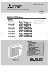
Page 6
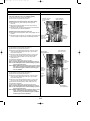
(2) Cautions for refrigerant piping work
New refrigerant R410A is adopted for replacement inverter series. Although the refrigerant piping work for R410A is same
as for R22, exclusive tools are necessary so as not to mix with different kind of refrigerant. Furthermore as the working
pressure of R410A is 1.6 time higher than that of R22, their sizes of flared sections and flare nuts are different.
1Thickness of pipes
Because the working pressure of R410A is higher compared to R22, be sure to use refrigerant piping with thickness
shown below. (Never use pipes of 0.7mm or below.)
Diagram below: Piping diameter and thickness
Thickness (mm)
Nominal
Outside
dimensions diameter (mm)
R410A
R22
0.8
0.8
6.35
1/4”
0.8
0.8
9.52
3/8”
0.8
0.8
12.70
1/2”
1.0
1.0
15.88
5/8”
—
1.0
19.05
3/4”
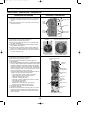
2Dimensions of flare cutting and flare nut
The component molecules in HFC refrigerant are smaller compared to conventional refrigerants. In addition to that,
R410A is a refrigerant, which has higher risk of leakage because of its working pressure higher than that of other refrigerants. Therefore, to enhance airtightness and intensity, flare cutting dimension of copper pipe for R410A have been specified separately from the dimensions for other refrigerants as shown below. The dimension B of flare nut for R410A also
have partly been changed to increase intensity as shown below. Set copper pipe correctly referring to copper pipe flaring
dimensions for R410A below. For 1/2” and 5/8”, the dimension B changes.
Use torque wrench corresponding to each dimension.
Dimension A
Dimension B
Flare cutting dimensions
Outside
Nominal
diameter
dimensions
6.35
1/4”
9.52
3/8”
12.70
1/2”
15.88
5/8”
19.05
3/4”
(mm)
Dimension A ( +0
-0.4 )
R410A
R22
9.0
9.1
13.0
13.2
16.2
16.6
19.4
19.7
—
23.3
Flare nut dimensions
Outside
Nominal
diameter
dimensions
6.35
1/4”
9.52
3/8”
12.70
1/2”
15.88
5/8”
19.05
3/4”
(mm)
Dimension B
R22
R410A
17.0
17.0
22.0
22.0
w36.0mm for
24.0
26.0
indoor unit
27.0
29.0 w
of RP4, 5
—
36.0
and 6
3Tools for R410A (The following table shows whether conventional tools can be used or not.)
R410A tools
Can R22 tools be used? Can R407C tools be used?
Tool exclusive for R410A
Tool exclusive for R410A
Tool for HFC refrigerant
Tool exclusive for R410A
Tool exclusive for R410A
Ester oil and alkylbenzene
Ester oil:
Alkylbenzene oil: minimum amount
oil (minimum amount)
Prevent compressor malfunction Tool exclusive for R410A
Safety charger
when charging refrigerant by
spraying liquid refrigerant
Prevent gas from blowing out Tool exclusive for R410A
Charge valve
when detaching charge hose
Vacuum drying and air
Vacuum pump
Tools for other refrigerants can
(Usable if equipped
(Usable if equipped
with adopter for reverwith adopter for reverpurge
be used if equipped with adopse flow)
se flow)
ter for reverse flow check
Flaring work of piping
Tools for other refrigerants
Flare tool
(Usable by adjusting
(Usable by adjusting
can be used by adjusting
flaring dimension)
flaring dimension)
flaring dimension
Bend the pipes
Tools for other refrigerants can be used
Bender
Tools for other refrigerants can be used
Cut the pipes
Pipe cutter
Tools for other refrigerants can be used
Welder and nitrogen gas cylinder Weld the pipes
Tools for other refrigerants can be used
Refrigerant charging scale Charge refrigerant
Vacuum gauge or thermis- Check the degree of vacuum. (Vacuum Tools for other refrigerants
valve prevents back flow of oil and refri- can be used
tor vacuum gauge and
gerant to thermistor vacuum gauge)
vacuum valve
Charge refrigerant
Charging cylinder
Tool exclusive for R410A
: Prepare a new tool. (Use the new tool as the tool exclusive for R410A.)
: Tools for other refrigerants can be used under certain conditions.
: Tools for other refrigerants can be used.
Tools and materials
Gauge manifold
Charge hose
Gas leak detector
Refrigerant recovery equipment
Refrigerant cylinder
Applied oil
Use
Air purge and refrigerant charge
Operation check and the two above
Gas leak check
Collection of refrigerant
Refrigerant charge
Apply to flared section
6
OC294-D-1.qxp
05.3.9 11:01 AM
3
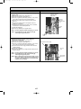
Page 7
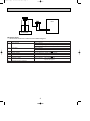
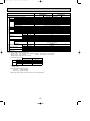
COMBINATION OF INDOOR AND OUTDOOR UNITS
Outdoor unit
Heat pump type
Indoor unit
Heat pump
without
electric heater
Service Ref.
Service
Manual No.
PEAD-RP·EA.UK
PEAD-RP·EA1.UK
—
PEAD-RP·GA.UK
—
PLA-RP·AA
PLA-RP·AA1
PUHZ-RP
2.5
4
3
1.6
2
VHA
VHA
VHA
VHA1 VHA1
5
6
VHA VHA VHA
VHA1 VHA1 VHA1
YHA YHA YHA
—
—
—
—
—
—
—
—
—
—
OC293
REVISED EDITION-B
PLA-RP·AA.UK OC297
PLA-RP·AA1.UK REVISED EDITION-D
PKA-RP·FAL
OC301
REVISED EDITION-A
PKA-RP·GAL OC305
PCA-RP·GA
4
VHA
OC311
—
—
—
—
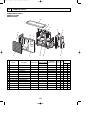
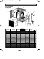
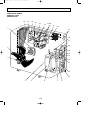
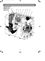
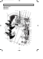
PART NAMES AND FUNCTIONS
PUHZ-RP2.5VHA
PUHZ-RP3VHA
PUHZ-RP1.6VHA
PUHZ-RP2VHA
PUHZ-RP2.5VHA1
PUHZ-RP3VHA1
PUHZ-RP4VHA PUHZ-RP4VHA1
PUHZ-RP5VHA PUHZ-RP5VHA1
PUHZ-RP6VHA PUHZ-RP6VHA1
PUHZ-RP4YHA
PUHZ-RP5YHA
PUHZ-RP6YHA
CHARGELESS SYSTEM
PRE-CHARGED REFRIGERANT IS SUPPLIED FOR PIPING LENGTH AT SHIPMENT.
(Max.30m(PUHZ-RP1.6~RP6))
The refrigerant circuit with LEV(Linear Expansion Valve) and power receiver always control the optimal refrigerant
level regardless of the length (30m max. and 5m min.) of piping. The additional refrigerant charging work during
installation often causes problems. Heretofore it is completely eliminated. This unique system improves the quality
and reliability of the work done.It also helps to speed up the installation time.
7
OC294-D-1.qxp
5
05.3.9 11:01 AM
Page 8
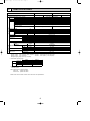
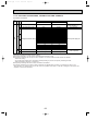
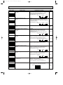
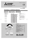
SPECIFICATIONS
PUHZ-RP1.6VHA
Service Ref.
Cooling
OUTDOOR UNIT
Function
Power supply (phase, cycle, voltage)
Running current
External finish
Refrigerant control
Compressor
Model
Motor output
Starter type
Protection devices
Crankcase heater
Heat exchanger
Fan
Fan(drive) o No.
Fan motor output
Airflow
Defrost method
Noise level
REFRIGERANT PIPING
Dimensions
Weight
Refrigerant
Charge
Oil (Model)
Pipe size O.D.
Connection method
Between the indoor &
outdoor unit
A
PUHZ-RP2VHA
Heating
Cooling
Single, 50Hz, 220/230/240V
4.23
6.16
Munsell 3Y 7.8/1.1
Linear Expansion Valve
Hermetic
SNB130FLBH
4.01
0.8
kW
Heating
6.47
1.1
Line start
HP switch
Discharge thermo
—
Plate fin coil
Propeller fan o 1
0.043
35(1,240)
Reverse cycle
44
46
800(31-1/2)
330+23(11-13/16+7/8)
600(23-5/8)
45(99)
R410A
2.5(5.5)
0.45(NEO22)
6.35(1/4)
12.7(1/2)
Flared
Flared
Max. 30m
Max. 50m
W
kW
K/min(CFM)
Cooling
Heating
W
D
H
dB
dB
mm(in.)
mm(in.)
mm(in.)
kg(lbs)
kg(lbs)
L
mm(in.)
mm(in.)
Liquid
Gas
Indoor side
Outdoor side
Height difference
Piping length
Notes1. Rating Conditions (ISO5151/13253 T1)
Cooling : Indoor : D.B. 27˚C(80˚F), W.B. 19˚C(66˚F) Outdoor : D.B. 35˚C(95˚F), W.B. 24˚C(75˚F)
Heating : Indoor : D.B. 20˚C(68˚F)
Outdoor : D.B. 7˚C(45˚F), W.B. 6˚C(43˚F)
Refrigerant piping length (one way) : 5m (16ft)
2. Guaranteed operating range
Outdoor
Indoor
D.B. 46˚C
Upper limit D.B. 35˚C, W.B. 22.5˚C
Cooling
D.B. -5˚C
Lower limit D.B. 19˚C, W.B. 15˚C
Upper limit
D.B. 21˚C, W.B. 15˚C
D.B. 28˚C
Heating
Lower limit
D.B. 17˚C
D.B. -11˚C, W.B. -12˚C
3. Guaranteed voltage
198~264V, 50Hz
4. Above data based on indicated voltage
Indoor Unit
1 phase 230V 50Hz
Outdoor Unit 1 phase 230V 50Hz
5. Refer to the service manual of indoor unit for tha indoor unit's specifications.
8
HP switch
Discharge thermo
OC294-D-1.qxp
05.3.9 11:01 AM
Page 9
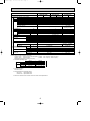
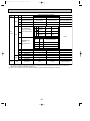
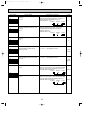
PUHZ-RP2.5VHA
PUHZ-RP2.5VHA1
Cooling
Heating
Service Ref.
OUTDOOR UNIT
Function
Power supply (phase, cycle, voltage)
Running current
External finish
Refrigerant control
Compressor
Model
Motor output
Starter type
Protection devices
Crankcase heater
Heat exchanger
Fan
Fan(drive) o No.
Fan motor output
Airflow
Defrost method
Noise level
Dimensions
A
HP switch
Discharge thermo
REFRIGERANT PIPING
Between the indoor &
outdoor unit
—
Plate fin coil
Propeller fan o 1
0.060
55(1,940)
Reverse cycle
47
48
950(37-3/8)
330+30(13+1-3/16)
943(37-1/8)
75(165)
R410A
W
kW
K/min(CFM)
Cooling
Heating
W
D
H
Charge
Connection method
1.4
kW
Weight
Refrigerant
Oil (Model)
Pipe size O.D.
6.61
PUHZ-RP3VHA
PUHZ-RP3VHA1
Cooling
Heating
Single, 50Hz, 220/230/240V
8.04
7.50
9.74
Munsell 3Y 7.8/1.1
Linear Expansion Valve
Hermetic
TNB220FMBH
1.6
Line start
dB
dB
mm(in.)
mm(in.)
mm(in.)
kg(lbs)
0.87(NEO22)
L
mm(in.)
Liquid
mm(in.)
Gas
Indoor side
Outdoor side
Height difference
Piping length
13.94
12.33
ANV33FDAMT
1.9
HP switch
LP switch
Discharge thermo
Propeller fan o 2
0.060+0.060
100(3,530)
49
51
1,350(53-1/8)
121(267)
5.5(12.1)·····RP4VHA
5.0(11.0)·····RP4VHA1
1.40(MEL56)
3.5(7.7)
kg(lbs)
PUHZ-RP4VHA
PUHZ-RP4VHA1
Heating
Cooling
9.52(3/8)
15.88(5/8)
Flared
Flared
Max. 30m
Max. 50m
Notes1. Rating Conditions (ISO5151/13253 T1)
Cooling : Indoor : D.B. 27˚C(80˚F), W.B. 19˚C(66˚F) Outdoor : D.B. 35˚C(95˚F), W.B. 24˚C(75˚F)
Heating : Indoor : D.B. 20˚C(68˚F)
Outdoor : D.B. 7˚C(45˚F), W.B. 6˚C(43˚F)
Refrigerant piping length (one way) : 5m (16ft)
2. Guaranteed operating range
Outdoor
Indoor
D.B. 46˚C
Upper limit D.B. 35˚C, W.B. 22.5˚C
Cooling
D.B. -5˚C
Lower limit D.B. 19˚C, W.B. 15˚C
Upper limit
D.B. 21˚C, W.B. 15˚C
D.B. 28˚C
Heating
Lower limit
D.B. 17˚C
D.B. -11˚C, W.B. -12˚C
3. Guaranteed voltage
360~440V, 50Hz
4. Above data based on indicated voltage
Indoor Unit
1 phase 230V 50Hz
Outdoor Unit 1 phase 230V 50Hz
5. Refer to the service manual of indoor unit for tha indoor unit's specifications.
9
Max. 75m
OC294-D-1.qxp
05.3.9 11:01 AM
Page 10
Service Ref.
OUTDOOR UNIT
Function
Power supply (phase, cycle, voltage)
Running current
External finish
Refrigerant control
Compressor
Model
Motor output
Starter type
Protection devices
Crankcase heater
Heat exchanger
Fan
Fan(drive) o No.
Fan motor output
Airflow
Defrost method
Noise level
Cooling
Heating
Dimensions
W
D
H
Weight
Refrigerant
A
kW
W
kW
K/min(CFM)
REFRIGERANT PIPING
Charge
Oil (Model)
Pipe size O.D.
Connection method
Between the indoor &
outdoor unit
dB
dB
mm(in.)
mm(in.)
mm(in.)
kg(lbs)
kg(lbs)
L
Liquid
mm(in.)
Gas
mm(in.)
Indoor side
Outdoor side
Height difference
Piping length
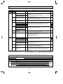
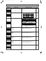
PUHZ-RP5VHA
PUHZ-RP6VHA
PUHZ-RP5VHA1
PUHZ-RP6VHA1
Cooling
Heating
Cooling
Heating
Single, 50Hz, 220/230/240V
15.80
17.50
20.73
20.37
Munsell 3Y 7.8/1.1
Linear Expansion Valve
Hermetic
ANV33FDAMT
2.4
2.9
Line start
HP switch, LP switch, Discharge thermo
—
Plate fin coil
Propeller fan o 2
0.060 +0.060
100(3,530)
Reverse cycle
50
52
950(37-3/8)
330+30(13+1-3/16)
1,350(53-1/8)
121(267)
R410A
5.5(12.1)·····RP5, 6VHA
5.0(11.0)·····RP5, 6VHA1
1.40(MEL56)
9.52(3/8)
15.88(5/8)
Flared
Flared
Max. 30m
Max. 75m
Notes1. Rating Conditions (ISO5151/13253 T1)
Cooling : Indoor : D.B. 27˚C(80˚F), W.B. 19˚C(66˚F) Outdoor : D.B. 35˚C(95˚F), W.B. 24˚C(75˚F)
Heating : Indoor : D.B. 20˚C(68˚F)
Outdoor : D.B. 7˚C(45˚F), W.B. 6˚C(43˚F)
Refrigerant piping length (one way) : 5m (16ft)
2. Guaranteed operating range
Indoor
Outdoor
D.B. 46˚C
Upper limit D.B. 35˚C, W.B. 22.5˚C
Cooling
D.B. -5˚C
Lower limit D.B. 19˚C, W.B. 15˚C
Upper limit
D.B. 21˚C, W.B. 15˚C
D.B. 28˚C
Heating
Lower limit
D.B. 17˚C
D.B. -11˚C, W.B. -12˚C
3. Guaranteed voltage
198~264V, 50Hz
4. Above data based on indicated voltage
Indoor Unit
1 phase 230V 50Hz
Outdoor Unit 1 phase 230V 50Hz
5. Refer to the service manual of indoor unit for tha indoor unit's specifications.
10
OC294-D-1.qxp
05.3.9 11:01 AM
Page 11
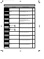
PUHZ-RP4YHA
Service Ref.
OUTDOOR UNIT
Function
Power supply (phase, cycle, voltage)
Running current
External finish
Refrigerant control
Compressor
Model
Motor output
Starter type
Protection devices
Crankcase heater
Heat exchanger
Fan
Fan(drive) o No.
Fan motor output
Airflow
Defrost method
Noise level
Dimensions
A
REFRIGERANT PIPING
Between the indoor &
outdoor unit
3.79
4.33
1.9
kW
K/min(CFM)
Cooling
Heating
W
D
H
PUHZ-RP6YHA
Cooling
Heating
3phase, 50Hz, 400V
4.85
5.41
Munsell 3Y 7.8/1.1
Linear Expansion Valve
Hermetic
ANV33FDBMT
2.4
Line start
HP switch
LP switch
Discharge thermo
50
52
49
51
dB
dB
mm(in.)
mm(in.)
mm(in.)
kg(lbs)
950(37-3/8)
330+30(13+1-3/16)
1,350(53-1/8)
135(298)
R410A
5.0(11.0)
kg(lbs)
1.40(MEL56)
9.52(3/8)
15.88(5/8)
Flared
Flared
Max. 30m
Max. 75m
L
mm(in.)
Liquid
mm(in.)
Gas
Indoor side
Outdoor side
Height difference
Piping length
Notes1. Rating Conditions (ISO5151/13253 T1)
Cooling : Indoor : D.B. 27˚C(80˚F), W.B. 19˚C(66˚F) Outdoor : D.B. 35˚C(95˚F), W.B. 24˚C(75˚F)
Heating : Indoor : D.B. 20˚C(68˚F)
Outdoor : D.B. 7˚C(45˚F), W.B. 6˚C(43˚F)
Refrigerant piping length (one way) : 5m (16ft)
2. Guaranteed operating range
Outdoor
Indoor
D.B. 46˚C
Upper limit D.B. 35˚C, W.B. 22.5˚C
Cooling
D.B. -5˚C
Lower limit D.B. 19˚C, W.B. 15˚C
Upper limit
D.B. 21˚C, W.B. 15˚C
D.B. 28˚C
Heating
Lower limit
D.B. 17˚C
D.B. -11˚C, W.B. -12˚C
3. Guaranteed voltage
342~456V, 50Hz
4. Above data based on indicated voltage
Indoor Unit
1 phase 230V 50Hz
Outdoor Unit 3 phase 400V 50Hz
5. Refer to the service manual of indoor unit for tha indoor unit's specifications.
11
Cooling
Heating
6.49
6.37
2.9
—
Plate fin coil
Propeller fan o 2
0.060+0.060
100(3,530)
Reverse cycle
W
Charge
Connection method
Heating
kW
Weight
Refrigerant
Oil (Model)
Pipe size O.D.
Cooling
PUHZ-RP5YHA
OC294-D-1.qxp
6
05.3.9 11:01 AM
Page 12
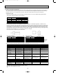
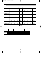
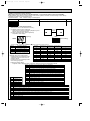
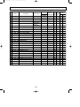
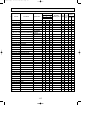
DATA
6-1. REFILLING REFRIGERANT CHARGE (R410A : kg)
10m
20m
Piping length (one way)
30m
40m
50m
60m
75m
Factory
charged
PUHZ-RP1.6VHA
2.1
2.3
2.5
2.7
2.9
—
—
2.5
PUHZ-RP2VHA
2.1
2.3
2.5
2.7
2.9
—
—
2.5
PUHZ-RP2.5VHA
PUHZ-RP2.5VHA1
3.1
3.3
3.5
4.1
4.7
—
—
3.5
PUHZ-RP3VHA
PUHZ-RP3VHA1
3.1
3.3
3.5
4.1
4.7
—
—
3.5
PUHZ-RP4VHA
5.1
5.3
5.5
6.1
6.7
7.3
7.9
5.5
PUHZ-RP5VHA
5.1
5.3
5.5
6.1
6.7
7.3
7.9
5.5
PUHZ-RP6VHA
5.1
5.3
5.5
6.1
6.7
7.3
7.9
5.5
4.6
4.8
5.0
5.6
6.2
6.8
7.4
5.0
4.6
4.8
5.0
5.6
6.2
6.8
7.4
5.0
4.6
4.8
5.0
5.6
6.2
6.8
7.4
5.0
Service Ref.
PUHZ-RP4VHA1
PUHZ-RP4YHA
PUHZ-RP5VHA1
PUHZ-RP5YHA
PUHZ-RP6VHA1
PUHZ-RP6YHA
Longer pipe than 30m, additional charge is
required.
6-2. COMPRESSOR TECHNICAL DATA
(at 20°C)
Unit
PUHZ-RP1.6,2VHA PUHZ-RP2.5,3VHA PUHZ-RP4,5,6VHA PUHZ-RP4,5,6YHA
Compressor model
SNB130FLBH
TNB220FMBH
ANV33FDAMT
ANV33FDBMT
U-V
Winding
Resistance U-W
(")
W-V
0.300 ~ 0.340
0.865 ~ 0.895
0.266
1.064
0.300 ~ 0.340
0.865 ~ 0.895
0.266
1.064
0.300 ~ 0.340
0.865 ~ 0.895
0.266
1.064
12
OC294-D-1.qxp
05.3.9 11:01 AM
Page 13
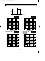
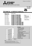
6-3. NOISE CRITERION CURVES
MICROPHONE
1m
UNIT
1.5m
GROUND
PUHZ-RP1.6VHA
PUHZ-RP2VHA
MODE SPL(dB)
COOLING
44
HEATING
46
PUHZ-RP2.5VHA, VHA1
PUHZ-RP3VHA, VHA1
LINE
80
70
NC-70
60
NC-60
50
NC-50
40
NC-40
30
NC-30
20
10
APPROXIMATE
THRESHOLD OF
HEARING FOR
CONTINUOUS
NOISE
63
125
NC-20
250
500
1000
2000
4000
8000
80
70
NC-70
60
NC-60
50
NC-50
40
NC-40
30
NC-30
20
10
APPROXIMATE
THRESHOLD OF
HEARING FOR
CONTINUOUS
NOISE
63
BAND CENTER FREQUENCIES, Hz
PUHZ-RP4VHA, VHA1
PUHZ-RP4YHA
MODE SPL(dB)
COOLING
49
HEATING
51
500
1000
2000
4000
8000
MODE SPL(dB)
COOLING
50
HEATING
52
LINE
90
OCTAVE BAND SOUND PRESSURE LEVEL, dB (0 dB = 0.0002 µbar)
OCTAVE BAND SOUND PRESSURE LEVEL, dB (0 dB = 0.0002 µbar)
250
PUHZ-RP5VHA, VHA1
PUHZ-RP6VHA, VHA1
PUHZ-RP5YHA
PUHZ-RP6YHA
LINE
80
70
NC-70
60
NC-60
50
NC-50
40
NC-40
30
NC-30
10
125
NC-20
BAND CENTER FREQUENCIES, Hz
90
20
LINE
90
OCTAVE BAND SOUND PRESSURE LEVEL, dB (0 dB = 0.0002 µbar)
OCTAVE BAND SOUND PRESSURE LEVEL, dB (0 dB = 0.0002 µbar)
90
MODE SPL(dB)
COOLING
47
HEATING
48
APPROXIMATE
THRESHOLD OF
HEARING FOR
CONTINUOUS
NOISE
63
125
NC-20
250
500
1000
2000
4000
8000
80
70
NC-70
60
NC-60
50
NC-50
40
NC-40
30
NC-30
20
10
APPROXIMATE
THRESHOLD OF
HEARING FOR
CONTINUOUS
NOISE
63
125
NC-20
250
500
1000
2000
4000
BAND CENTER FREQUENCIES, Hz
BAND CENTER FREQUENCIES, Hz
13
8000
OC294-D-1.qxp
7
05.3.9 11:01 AM
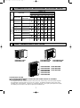
Page 14
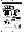
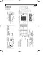
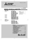
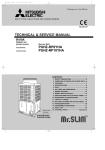
OUTLINES AND DIMENSIONS
Unit : mm
PUHZ-RP1.6VHA
PUHZ-RP2VHA
400
[33 drain hole
347.5
365
300
Air intake
[33 drain hole
330
155
152
43.6
Air intake
45.4
40
18
23
32.5
4-10 o 21 oval hole
(M10 foundation bolt)
Service panel
Service panel
for charge plug
Air discharge
Handle for
moving
150
Connection for
gas pipe
90
10
155
300
43
35
600
Connection for
liquid pipe
183
69
287.5
Service port
Installation bolt pitch: 500
800
1. FOUNDATION BOLTS
2. PIPING-WIRING DIRECTION
Please secure the unit firmly Piping and wiring connection can
with 4 foundation (M10) bolts. be made from the rear direction only.
(Bolts, washer and nut must
be purchased locally.)
Free space around the outdoor unit
(basic example)
100
mm
w1
re
r mo
mo
m
100
18 or below
100 mm or more as long as
no obstacle is placed on the
rear and light-and-left sides
of the unit.
Basically open
3. ATTACHING THE CONDUIT
In order to attach the conduit, it is
necessary to fix the metal plate with
2 screws to the back panel. Procure
the metal plate and make screw holes
locally. It is recommended to use the
metal plate shown below. Align the
metal plate to the marks on the unit
and attach it.
<Foundation bolt height>
FOUNDATION
or m
ore
w1
w2
w The position and the size of
conduit hole depend on the
conduit to be used.
500
mm
or
re
mo
350
mm
40
20
or m
ore
2 sides should be open in
the right, left and rear side.
80
Minimum installation space for outdoor unit
60
w Conduit hole
w 1 In the place where short cycle tends to occur, cooling and heating
capacity and power consumption might get lowered 10%. Air outlet
guide (optional PAC-SG58SG) will help them improve.
w 2 If air discharges to the wall, the surface might get stained.
Holes for metal plate fixing screw
w The size of hole depends on the
screw to be used.
14
OC294-D-1.qxp
05.3.9 11:01 AM
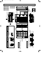
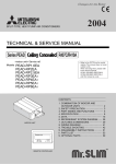
Page 15
Unit : mm
Ov
Ov
e
r1
0m
m
er
50
0m
m
F
R
E
E
Ov
er
10
e
Ov
mm
r1
00
mm
PUHZ-RP2.5VHA
PUHZ-RP2.5VHA1
PUHZ-RP3VHA
PUHZ-RP3VHA1
15
mm
50
r1
Ove
FREE
m
0m
r1
Ove
mm
50
r1
Ove
10
Service space
Over
Front piping hole
(Knock-Out)
92
[92
Front trunking hole 40
(Knock-Out)
65
45
Power supply wiring hole
(2-[27Knock-Out)
500
19
92
75
Right piping hole
(Knock-Out)
55
[92
Air intake
Handle for moving
Piping Knock-Out Hole Details
55
27
Over
Dimensions of space needed
for service access are
shown in the below diagram.
1 • • • Refrigerant GAS pipe connction (FLARE)[15.88 (5/8F)
2 • • • Refrigerant LIQUID pipe connection (FLARE)[ 9.52 (3/8F)
w1 • • • Indication of STOP VALVE connection location.
Example of Notes
m
0m
r1
Ove
63
73
100
Less than
40
65
45
Right trunking hole
(Knock-Out)
92
[92
40
FOUNDATION
Rear piping hole
(Knock-Out)
Rear trunking hole
(Knock-Out)
Power supply wiring hole
(2-[27Knock-Out)
Handle for moving
Handle for moving
Side Air Intake
Rear Air Intake
Piping and wiring connections
can be made from 4 directions:
FRONT,Right,Rear and Below.
Please secure the unit firmly
with 4 foundation (M10) bolts.
(Bolts and washers must be
purchased locally.)
<Foundation bolt height>
4 PIPING-WIRING DIRECTIONS
Power supply wiring hole
(2-[27Knock-Out)
500
The diagram below shows a
basic example.
Explantion of particular details are
given in the installation manuals etc.
23 27 92
30
Over
Over
3 FOUNDATION BOLTS
175
322
600
145
Air Discharge
Installation Feet
66
175
2-U Shaped notched holes
(Foundation Bolt M10)
Handle for moving
30
220
145
145
Earth terminal
950
42
Side Air Intake
1350
2 SERVICE SPACE
73 63
635
371
Rear Air Intake
Drain hole
(5-[33)
71
2
1
Handle for moving
Service panel
Terminal connection
Left • • • Power supply wiring
Right • • Indoor/Outdoor wiring
2-12o36 Oval holes
(Foundation Bolt M10)
71
1 FREE SPACE (Around the unit)
73 63
23
Front piping cover
RP·YHA
RP·VHA
RP·VHA1
Bottom piping hole
(Knock-Out)
A
930
1,076
Rear piping cover
PUHZ-RP4YHA
PUHZ-RP5YHA
PUHZ-RP6YHA
23
55
27
330
30
23
219
417
w1 443
16
81
19
45
56
370
53
28
PUHZ-RP4VHA
PUHZ-RP4VHA1
PUHZ-RP5VHA
PUHZ-RP5VHA1
PUHZ-RP6VHA
PUHZ-RP6VHA1
A
05.3.9 11:01 AM
w1 447
OC294-D-1.qxp
Page 16
Unit : mm
OC294-D-1.qxp
05.3.9 11:01 AM
8
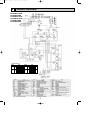
Page 17
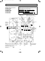
WIRING DIAGRAM
PUHZ-RP1.6VHA
PUHZ-RP2VHA
PUHZ-RP2.5VHA
PUHZ-RP2.5VHA1
PUHZ-RP3VHA
PUHZ-RP3VHA1
W1
W2
W1 MODEL SELECT
MODELS
SW6
MODELS
ON
1.6V OFF
SW6
ON
2.5V OFF
1 2 3 4 5 6
2V
ON
OFF
1 2 3 4 5 6
3V
1 2 3 4 5 6
ON
OFF
1 2 3 4 5 6
W2 Only PUHZ-RP2.5, 3VHA.
17
OC294-D-1.qxp
05.3.9 11:01 AM
Page 18
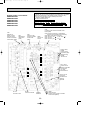
PUHZ-RP4VHA
PUHZ-RP4VHA1
PUHZ-RP5VHA
PUHZ-RP5VHA1
PUHZ-RP6VHA
PUHZ-RP6VHA1
W1
Only PUHZ-RP4VHA1
PUHZ-RP5VHA1
PUHZ-RP6VHA1
W1 MODEL SELECT
MODELS
SW6
4V
ON
OFF
1 2 3 4 5 6
5V
ON
OFF
1 2 3 4 5 6
6V
ON
OFF
1 2 3 4 5 6
18
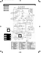
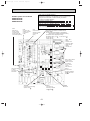
Page 19
63H
63L
TH4
SV2
1 (BLU)
3
12345
CN5
(WHT)
M-NET
SV
<w1 MODEL SELECT>
SW6
MODELS
P.B.
CT2
+
TB-W
BLK
TB-V
WHT W
RED V
12
12
CN5 CN4
(RED) (WHT)
ON
OFF
BLK
TB-L2
WHT
TB-L1
RED
TB-C1
CB1
CNAC1 1
(WHT)
N.F.
1 2
1 2 3 4 5 6
ON
OFF
1 2
TB-N1
CB2
CK
L1-A1
S3
TB1
L1
1 2 3 4 5 6
123
CN7
(WHT)
TB-P2
S2
NO FUSE
BREAKER
1 2
ON
OFF
L3-OU
TB-L3
RS
TB2
S1
INDOOR
UNIT
-
RP6Y
1 2 3 4 5 6
U
TB-U
CT1
+
MC
RP5Y
ON
OFF
SW10
ON
OFF
CNCT 1 2
(RED)
3
1
3 CNAC2
(RED)
L1-A2
1234567
CN2
(WHT)
ON
OFF
CK-OU
123
CN7
(WHT)
RP4Y
L2-A2
21S4
3
TB7
A B S
SS
1 (WHT)
L1-OU
3
21S4
1 (GRN)
N-IN
RED
F4
L2-OU
F1
CNS
(WHT) 3 2 1
123
CONV.B.
L1-IN
F3
CNAC
(WHT)
12
34
X55
F2
CN4
(WHT)
21
L3-A2
CNDC
(PNK)
w1
CN51 CNDM CN3S
(WHT) (WHT) (WHT)
12345 123 123
1
CN2
(WHT)
1234567
X51
TRANS
SW12
LED3
LED4
CND
(WHT)
CN31
LED2
LED1
w1
SW11
SW1
12
CN2M
LED5 (WHT)
1 2 3 4 5 6 7 8 9 10 11121314
CNM
3
F5
123456 123 12345
LEV-B CNVMNT CNMNT
(RED)
(WHT) (WHT)
X52
MF2
1 3
63L
(RED)
123456
LEV-A
(WHT)
M-NET ADAPTER (OPTION)
SW9 SW7
4 5 6 7 CNF2
(WHT)
12 12
TH3 TH4
(WHT) (WHT)
LED1
1
1234
TH7/6
(RED)
LED2
4 5 6 7 CNF1 1 2 3
(WHT) CN3N
63H
(YLW)
3 1
1
MF1
LEV
LEV
C.B.
SW10
TH3
SW6
TH7 TH6
SW1
PUHZ-RP4YHA
PUHZ-RP5YHA
PUHZ-RP6YHA
SW4 SWP SW8 SW5
05.3.9 11:01 AM
ORN
OC294-D-1.qxp
ACL1
RED
LI1
LO1
RED
L2
WHT
LI2
LO2
WHT
L3
BLK
LI3
LO3
BLK
NI
NO
ACL2
POWER SUPPLY
3N~
400V
50Hz
ACL3
N
BLU
GD1
SYMBOL
TB1
TB2
MC
MF1,MF2
21S4
SV
63H
63L
TH3
TH4
TH6
TH7
LEV
ACL1~ACL4
CB1,CB2
CK
RS
P.B.
TB-U/V/W
TB-L1/L2/L3
TB-P2
TB-C1
TB-N1
CT1, CT2
CN2
CN4
CN5
CN7
NAME
SYMBOL
N.F.
Terminal Block <Power Supply >
Terminal Block <Indoor/Outdoor >
LI1/LI2/LI3/NI
Motor for Compressor
LO1/LO2/LO3/NO
Fan Motor
CNAC1
Solenoid Valve (Four-Way Valve)
CNAC2
Solenoid Valve (Bypass Valve)
CNCT
High Pressure Switch
CNDC
CNL
Low Pressure Switch
Thermistor <Outdoor Pipe>
GD1
CONV.B
Thermistor <Discharge>
Thermistor <Outdoor 2-Phase Pipe>
L1-A1/IN
L1-A2/OU
Thermistor <Outdoor>
L2-A2/OU
Linear Expansion Valve
L3-A2/OU
Reactor
N-IN
Main Smoothing Capacitor
CK-OU
Capacitor
CN7
Rush Current Protect Resistor
Power Circuit Board
C.B.
F1,F2
Connection Terminal <U/V/W-Phase>
Connection Terminal <L1/L2/L3-Power Supply>
F3,F4
SW1
Connection Terminal
Connection Terminal
SW4
Connection Terminal
SW5
Current Trans
Connector
SW6
Connector
SW7
Connector
SW8
Connector
SW9
GD2
NAME
Noise Filter Circuit Board
Connection Terminal <L1/L2/L3/N-Power Supply>
Connection Terminal <L1/L2/L3/N-Power Supply>
Connector
Connector
Connector
Connector
Connector
Connection Terminal <Ground>
Converter Circuit Board
Connection Terminal <L1-Power Supply>
Connection Terminal <L1-Power Supply>
Connection Terminal <L2-Power Supply>
Connection Terminal <L3-Power Supply>
Connector
Connector
Connector
Controller Circuit Board
FUSE <6.3 A>
FUSE <6.3 A>
Switch <Forced Defrost, Defect History Record
Reset, Refrigerant Adress>
Switch <Test Operation>
Switch <Function Switch>
Switch <Model Select>
Switch <Function Switch>
Switch <Function Switch>
Switch <Function Switch>
M-NET ADAPTER
TB7
CN5
CND
CN2M
SW1
SW11
Terminal Block <M-NET connection >
Connector <Transmission>
Connector <Power Supply>
Connector <M-NET communication>
Switch <Status of communication>
Switch <Address setting: 1st digit>
SW12
LED1
LED2
LED3
LED4
LED5
Switch <Address setting. 2nd digit >
LED <Power Supply: DC5V>
LED <Connection to Outdoor Unit>
LED <Transmission: Sending>
LED <Transmission: Receiving>
LED <Power Supply: DC12V>
19
CNDC 1
(PNK)
SYMBOL
SW10
SWP
CN31
CNAC
CNS
CNDC
21S4
SV2
SS
CN2
CN4
LEV-A/LEV-B
63H
63L
TH3
TH4
TH7/6
CNF1/CNF2
LED1/LED2
CNM
CNVMNT
CNMNT
CN3S
CNDM
CN51
3
3
1 CNL
(BLU)
NAME
Switch <Model Select>
Switch <Pump Down>
Connector <Emergency Operation>
Connector
Connector
Connector
Connector <Four-Way Valve>
Connector <Bypass Valve>
Connector <Connection for Option>
Connector
Connector
Connector <LEV>
Connector <High Pressure Switch>
Connector <Low Pressure Switch>
Connector <Thermistor>
Connector <Thermistor>
Connector <Thermistor>
Connector <Fan Motor Operation>
LED <Operatiion Inspection Indicators>
Connector <A-Control Service Inspection Kit>
Connector <Connect to Optional M-NET Adapter Board>
Connector <Connect to Optional M-NET Adapter Board>
Connector < Connection for Option>
Connector < Connection for Option>
Connector < Connection for Option>
BLU
ACL4
OC294-D-1.qxp
9
05.3.9 11:01 AM
Page 20
WIRING SPECIFICATIONS
Indoor unit – Outdoor unit wiring for PUHZ-RP1.6-6VHA and PUHZ-RP1.6-6VHA1
The cable shall not be lighter than design 245 IEC or 227 IEC.
The cable length may vary depending on the condition of installation, humidity or materials, etc.
Cross section
of cable
Wire size
(mm2)
Number
of wires
2.5
3
Clockwise : S1-S2-S3
2.5
3
Not applicable
(Because center wire has no cover finish)
1.5
4
From left to right : S1-Open-S2-S3
(18)
✽3
2.5
4
Clockwise : S1-S2-S3-Open
Connect S1 and S3 to the opposite angle
30
✽4
Polarity
L(m) ✽5
Round
Flat
(30)
✽1
Not
applicable
✽2
Flat
Round
✽1 : In case that cable with stripe of yellow and green is available.
✽2 : In the flat cables are connected as this picture, they can be used up to 30m.
(3C Flat cable ✕ 2)
S1 S2 S3
✽3 : In case of regular polarity connection (S1-S2-S3), wire size is 1.5mm2.
✽4 : In case of regular polarity connection (S1-S2-S3).
✽5 : Mentioned cable length is just a reference value.
It may be different depending on the condition of installation, humidity or materials, etc.
Be sure to connect the indoor-outdoor connecting cables directly to the units (no intermediate
connections).
Intermediate connections can lead to communication errors if water enters the cables and causes
insufficient insulation to ground or a poor electrical contact at the intermediate connection point.
(If an intermediate connection is necessary, be sure to take measures to prevent water from entering
the cables.)
20
OC294-D-1.qxp
05.3.9 11:01 AM
Page 21
Indoor unit – Outdoor unit wiring for PUHZ-RP4, 5, 6YHA
The cable shall not be lighter than design 245 IEC or 227 IEC.
For 4, 5, 6Y application, use shield wire. (For EMC DIRECTIVE)
The shield part must be grounded with the indoor unit or the outdoor unit, not with both.
The cable length may depending on the condition of installation, humidity or materials, etc.
Wire No. o Size (E)
Indoor unit-Outdoor unit
Indoor unit-Outdoor unit earth
Max. 45m
Max. 50m
Max. 80m
3 o 1.5 (polar)
3 o 2.5 (polar)
3 o 2.5 (polar) and S3 separated
1 o Min. 1.5
1 o Min. 2.5
1 o Min. 2.5
If 1.5E used, Max. 45m.
If 2.5E used, Max. 50m.
If 2.5E used and S3 separated, Max. 80m.
When the shield line is not used, several dB is exceeded with 30 ~ 40 MHz .
(There is a possibility to be used by the wireless for the ship etc. though it is not used for
radio and TV.)
Be sure to connect the indoor-outdoor connecting cables directly to the units (no intermediate
connections).
Intermediate connections can lead to communication errors if water enters the cables and causes
insufficient insulation to ground or a poor electrical contact at the intermediate connection point.
(If an intermediate connection is necessary, be sure to take measures to prevent water from entering
the cables.)
21
OC294-D-1.qxp
10
05.3.9 11:01 AM
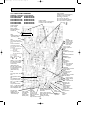
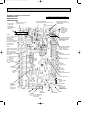
Page 22
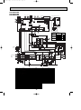
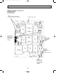
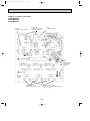
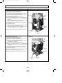
REFRIGERANT SYSTEM DIAGRAM
PUHZ-RP1.6VHA
PUHZ-RP2VHA
Heat exchanger
Stop valve
(with service port)
Refrigerant GAS pipe
connection(1/2F)
Thermistor TH6
(Outdoor 2-phase pipe)
Charge plug
Solenoid valve
(Four-way valve)
Thermistor TH7
(Outdoor)
Strainer
#50
Thermistor TH3
(Outdoor pipe)
Muffler
Distributor
High pressure
switch 63H
Thermistor TH4
(Discharge)
Muffler
Linear
expansion valve B
Linear expansion valve A
Stop valve
Refrigerant LIQUID pipe
connection(1/4F)
Compressor
Power
receiver
Strainer
#100
Strainer
#100
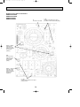
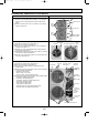
PUHZ-RP2.5VHA
PUHZ-RP2.5VHA1
PUHZ-RP3VHA
PUHZ-RP3VHA1
Ball valve
Refrigerant GAS pipe
connection(5/8F)
Heat exchanger
Strainer
#50
Thermistor TH6
(Outdoor 2-phase pipe)
4-way valve
Oil separator
Charge plug
(High pressure)
Bypass valve
Charge plug
(Low pressure)
Capillary tube
O.D.4.0OI.D.2.4OL500
Strainer
#100
Thermistor TH4
(Discharge)
Strainer
#100
Stop valve
(with service port)
Strainer
#100
Power
receiver
Linear
expansion
valve B
Thermistor TH3
(Outdoor pipe)
Distributor
High pressure
switch 63H
Capillary tube
O.D.2.5OI.D.0.6OL1000
Refrigerant LIQUID pipe
connection(3/8F)
Thermistor TH7
(Outdoor)
Muffler Compressor
Linear expansion valve A
Strainer
#100
22
OC294-D-1.qxp
05.3.9 11:01 AM
Page 23
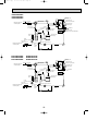
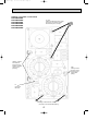
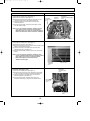
PUHZ-RP4VHA
PUHZ-RP5VHA
PUHZ-RP6VHA
Refrigerant GAS pipe
connection(5/8F)
Heat exchanger
Ball valve Strainer
#50
Thermistor TH6
(Outdoor 2-phase pipe)
Solenoid valve
(Four-way valve)
Thermistor TH3
(Outdoor pipe)
Charge plug
(High pressure)
Muffler
Charge plug
(Low pressure)
Distributor
Low pressure
switch 63L
Strainer
#100
High pressure
switch 63H
Stop valve
(with service port)
Refrigerant LIQUID pipe
connection(3/8F)
Power
receiver
Strainer
#100
Compressor
Linear expansion valve A
Restrictor
valve
Strainer
#100
Strainer
#100
Strainer
#100
Solenoid valve
(Bypass valve)
Replace filter
PUHZ-RP4VHA1
PUHZ-RP5VHA1
PUHZ-RP6VHA1
Refrigerant GAS pipe
connection(5/8F)
Capillary tube
(O.D.4.0OI.D.3.0OL200)O2pcs
Thermistor TH4
(Discharge)
Strainer
#100
Linear
expansion valve B
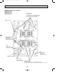
PUHZ-RP4YHA
PUHZ-RP5YHA
PUHZ-RP6YHA
Heat exchanger
Ball valve Strainer
#50
Low pressure
switch 63L
Strainer
#100
Distributor
High pressure
switch 63H
Thermistor TH4
(Discharge)
Strainer
#100
Stop valve
(with service port)
Strainer
#100
Thermistor TH3
(Outdoor pipe)
Muffler
Charge plug
(Low pressure)
Linear
expansion valve B
Thermistor TH7
(Outdoor)
Thermistor TH6
(Outdoor 2-phase pipe)
Solenoid valve
(Four-way valve)
Charge plug
(High pressure)
Refrigerant LIQUID pipe
connection(3/8F)
Thermistor TH7
(Outdoor)
Power
receiver
Strainer
#100
Compressor
Linear expansion valve A
Restrictor
valve
Strainer
#100
Strainer
#100
Replace filter
23
Solenoid valve
(Bypass valve)
OC294-D-1.qxp
05.3.9 11:01 AM
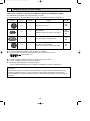
Page 24
Applicable extension pipe for each model
The height difference between indoor and outdoor unit should be kept within 30 m for all models.
(1) 1:1 system
(a) Maximum pipe length
<Table 1> Pipe length for 1:1 system
Liquid OD
[6.35
pipe
t0.8
(mm) Thickness
Gas OD
[12.7
[9.52
pipe
t0.8
t0.8
(mm) Thickness
30m
10m
RP1.6
RP2
RP2.5
RP3
RP4
RP5
RP6
[9.52
[12.7
t0.8
50m
50m
10m
10m
[15.88
[12.7
t1.0
t0.8
30m
30m
10m
10m
t0.8
[15.88
[19.05
[15.88
[19.05
t1.0
t1.0
t1.0
t1.0
30m (*1)
30m (*1)
50m
50m
75m (*2)
75m (*2)
75m (*2)
30m
30m
30m
30m
50m (*1)
50m (*1)
50m (*1)
30m
30m
50m
50m
50m
50m (*1)
50m (*1)
50m (*1)
*1: Set DIP SW8-1 on outdoor unit controller board to ON.
*2: The maximum length is 50 m in case of using existing pipes.
[Marks in the table above]
: Standard piping
: It can be used, however, additional refrigerant charge is required when the pipe length exceeds 20m.
: It cannot be used.
: It can be used.
: It can be used, however, the capacity is lowered.
Refer to (c) Capacity correction.
Refer to <table 4>.
(b) Adjusting the amount of refrigerant
• Additional refrigerant charge is not necessary for the pipe length up to 30 m. When the pipe length exceeds 30 m or service
(refrigerant replacement) is performed, charge proper amount of refrigerant for each pipe length referring to table below.
Use refrigerant R410A. Use charge hose exclusive for R410A.
• When charging additional refrigerant, charge the refrigerant from low-pressure side of the port valve using a safety charger.
• Make sure that air purge for this unit at refrigerant replacement is performed from both high-pressure check valve and service port. If air purge is performed only from one of them, air in not purged enough.
• When replacing refrigerant, charge the refrigerant from service port. When charged refrigerant is less than specified amount,
charge the refrigerant again from low pressure side of the port valve using a safety charger.
• Tighten the service port cap (nut) of stop valve firmly. The tightening torque is 12 to 16 N·m. (to prevent slow-leak)
• Check additional refrigerant charging amount referring to table 4 when liquid pipe is one size larger than standard diameter,
and table 2 when the pipe is standard diameter.
<Table 2> Additional refrigerant charging amount for pipe of standard diameter
Additional refrigerant charging amount for pipe
Permitted
Height
Number of
length exceeding 30 m (kg)
Outdoor unit
pipe length
difference
bends
31 — 40m 41 — 50m 51 — 60m 61 — 75m
50m or less
0.2kg
0.4kg
—
—
50m or less
PUHZ-RP2.5, 3VHA, 2.5, 3VHA1
PUHZ-RP4 6VHA, RP4 6VHA1, RP4 6YHA 75m or less
0.6Kg
1.2Kg
—
—
0.6kg
1.2kg
1.8kg
2.4kg
PUHZ-RP1.6, 2VHA
15
30m or
above
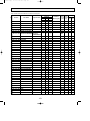
<Table 3>
Recharge refrigerant amount or additional amount in parentheses
Permitted
pipe length 10m or below 11 — 20m 21 — 30m 31 — 40m 41 — 50m 51 — 60m 61 — 75m
Outdoor unit
PUHZ-RP1.6, 2VHA
50m or less
2.1
2.3
2.5
PUHZ-RP2.5, 3VHA
PUHZ-RP2.5, 3VHA1
50m or less
3.1
3.3
3.5
PUHZ-RP4-6VHA
75m or less
PUHZ-RP4-6VHA1
PUHZ-RP4-6YHA
75m or less
5.1
4.6
5.3
4.8
5.5
5.0
2.7
2.9
—
—
(0.2)
(0.4)
—
—
—
4.1
4.7
—
(0.6)
(1.2)
—
—
6.1
6.7
7.3
7.9
(0.6)
(1.2)
(1.8)
(2.4)
5.6
6.2
6.8
7.4
(0.6)
(1.2)
(1.8)
(2.4)
<Table 4> Required additional charge when the pipe size is larger than the standard diameter
Liquid pipe dia Chargeless Max. pipe length Refrigerant amount to be added
RP1.6, 2
[9.52
20m
30m
60 g per 1 m longer than 20 m
RP2.5, 3
[12.7
20m
30m
100 g per 1 m longer than 20 m
RP4-6
[12.7
20m
50m
100 g per 1 m longer than 20 m
24
OC294-D-1.qxp
05.3.9 11:01 AM
Page 25
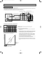
(c) Capacity correction
Cooling and heating capacity is lowered according to pipe length. Capacity can be obtained by referring to the capacity
curves below. When the diameter of gas pipe is one size smaller than standard diameter, cooling capacity is lowered comparing to the standard diameter. The lowered capacity can be obtained by referring to capacity curves for gas pipe which is
one size smaller than standard size.
Corrected pipe length (m) = actual pipe length (m) + number of bends x 0.3 (m)
1 Capacity curves for PUHZ-RP • HA model <Standard size>
Cooling
Heating
100
Heating RP1.6, 2, 2.5,
3, 4, 5 and 6 models
Cooling RP1.6, 2.5 models (Up to 55m for RP1.6,
2, 2.5, 3 model)
Cooling RP3 model
Capacity ratio [%]
95
90
85
Cooling RP2, 4 models
80
Cooling RP5 model
75
Cooling RP6 model
Note: The permitted pipe length is up to 55m for RP1.6, 2, 2.5, 3 model.
70
5
10
15
20
25
30
35
40
45
50
55
60
65
70
75
80
Corrected pipe length
2 Capacity curve for PUHZ-RP1.6, 2 models
<When gas pipe is one size smaller than standard size>
100
Heating RP1.6, RP2
Capacity ratio [%]
95
90
Cooling RP2
85
Cooling RP1.6
80
5
10
15
20
25
30
35
Corrected pipe length
25
40
45
50
55
OC294-D-1.qxp
05.3.9 11:01 AM
Page 26
3 Capacity curve for PUHZ-RP2.5, 3 models
<When gas pipe is one size smaller than standard size>
100
Heating RP2.5, RP3
Capacity ratio [%]
95
90
Cooling RP2.5
85
80
Cooling RP3
5
10
15
20
25
30
35
40
45
50
55
Corrected pipe length
4 When gas pipe is one size larger than standard size for PUHZ-RP4, 5 and 6.
1 Capacity can be obtained by referring to capacity curves of standard size.
26
OC294-D-1.qxp
05.3.9 11:01 AM
Page 27
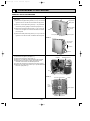
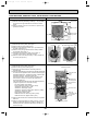
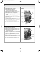
1. Refrigerant collecting (pump down)
Perform the following procedures to collect the refrigerant when moving the indoor unit or the outdoor unit.
1Before collecting the refrigerant, first make sure that the all of the SW5 DIP switches for function changes on the control
board of the outdoor unit are set to OFF. If all of the SW5 switches are not set to OFF, record the settings and then set all of
the switches to OFF. Now, start refrigerant collecting operation. After moving the unit to a new location and completing the
test run, set the SW5 switches to the previously recorded settings.
2Turn on the power supply (circuit breaker).
wWhen power is supplied, make sure that “CENTRALLY CONTROLLED” is not displayed on the remote controller. If
“CENTRALLY CONTROLLED” is displayed, the refrigerant collecting (pump down) cannot be completed normally.
3After the liquid stop valve is closed, set the SWP switch on the control board of the outdoor unit to ON. The compressor
(outdoor unit) and ventilators (indoor and outdoor units) start operating and refrigerant collecting operation begins. LED1 and
LED2 on the control board of the outdoor unit are lit.
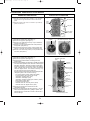
wSet the SWP switch (push-button type) to ON in order to perform refrigerant collecting operation only when the unit is
stopped. However, refrigerant collecting operation cannot be performed until compressor stops even if the unit is stopped.
Wait three minutes until compressor stops and set the SWP switch to ON again.
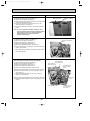
4Because the unit automatically stops in about two to three minutes after the refrigerant collecting operation (LED1 is not lit
and LED2 is lit), be sure to quickly close the gas stop valve.
wIn case the outdoor unit is stopped when LED1 is lit and LED2 is not lit, open the liquid stop valve completely, and then
repeat step 3 three minutes later.
wIf the refrigerant collecting operation has been completed normally (LED1 is not lit and LED2 is lit), the unit will remain
stopped until the power supply is turned off.
5Turn off the power supply (circuit breaker.)
2. Unit replacement operation
When reusing the existing pipes that carried R22 refrigerant for the RP4, RP5 and RP6 models, replacement operation
must be performed before performing a test run.
1If new pipes are used, these procedures are not necessary.
2If existing pipes that carried R22 refrigerant are used for the RP3 model, these procedures are not necessary. (The replacement operation cannot be performed.)
3During replacement operation, “C5” is displayed on “A-Control Service Tool(PAC-SK52ST)”. (This is applied to only RP4,
RP5 and RP6 models.)
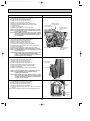
• Replacement operation procedures
1Turn on the power supply.
2Set DIP switch SW8-2 on the control board of the outdoor unit to ON to start replacement operation.
• The replacement operation is performed using the cooling system. Cool air will flow from the indoor unit during the replacement operation.
• During the replacement operation, TEST RUN is displayed on the remote controller and LED1 (green) and LED2 (red) on the
control board of the outdoor unit flash together.
3Replacement operation requires at least two hours to complete.
• After setting switch SW8-2 to ON, the unit automatically stops after two hours.
• Replacement operation can be performed repeatedly by setting switch SW8-2 from OFF to ON. Make sure to perform the
operation more than 2 hours. (If the operation is performed less than 2 hours, the existing pipes cannot be cleaned
enough and the unit may be damaged.)
• If replacement operation is performed over 2 hours, this action is recorded into nonvolatile memory of control board.
4Set switch SW8-2 to OFF. (Replacement operation is completed.)
wThe unit can be operated normally by remote controller even if SW8-2 remains ON.
wIf the indoor temperature is less than 15:, the compressor will operate intermittently but the unit is not faulty.
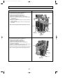
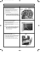
3. Start and finish of test run
• Operation from the indoor unit
Execute the test run using the installation manual for the indoor unit.
• Operation from the outdoor unit
By using the DIP switch SW4 on the control board of outdoor unit, test run can be started and finished, and its operation
mode (cooling/heating) can be set up.
<SW4>
1Set the operation mode (cooling/heating) using SW4-2.
2Turn on SW4-1 to start test run with the operation mode set by SW4-2.
C D
3Turn off SW4-1 to finish the test run.
ON
OFF
• There may be a faint knocking sound around the machine room after power is supplied, but this is
1
2
no problem with product because the linear expansion pipe is just moving to adjust opening pulse.
A B
• There may be a knocking sound around the machine room for several seconds after compressor
C operation
starts operating, but this is no problem with product because the check valve, itself, generates the A Stop
B Cooling D Heating
sound because pressure difference is small in the refrigerant circuit.
Note:
The operation mode cannot be changed by SW4-2 during test run. (To change test run mode, stop the unit by SW4-1,
change the operation mode and restart the test run by SW4-1.)
27
OC294-D-1.qxp
11
05.3.9 11:01 AM
Page 28
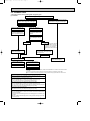
TROUBLESHOOTING
11-1. TROUBLESHOOTING
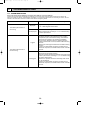
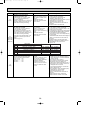
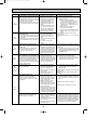
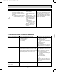
<Error code display by self-diagnosis and actions to be taken for service (summary)>
Present and past error codes are logged and displayed on the wired remote controller and control board of outdoor unit.
Actions to be taken for service, which depends on whether or not the inferior phenomenon is reoccurring at service, are summarized in the table below. Check the contents below before investigating details.
Unit conditions at service
Actions to be taken for service (summary)
Error code
Displayed
Judge what is wrong and take a corrective action according
to “11-4. Self-diagnosis action table”.
Not displayed
Conduct trouble shooting and ascertain the cause of the
inferior phenomenon according to “11-5. Troubleshooting
by inferior phenomena”.
Logged
1Consider the temporary defects such as the work of
protection devices in the refrigerant circuit including
compressor, poor connection of wiring, noise and etc.
Re-check the symptom, and check the installation
environment, refrigerant amount, weather when the
inferior phenomenon occurred, matters related to wiring
and etc.
2Reset error code logs and restart the unit after finishing
service.
3There is no abnormality concerning of parts such as
electrical component, controller board, remote controller
and etc.
Not logged
1Re-check the abnormal symptom.
2Conduct trouble shooting and ascertain the cause of the
inferior phenomenon according to “11-5. Troubleshooting
by inferior phenomena”.
3Continue to operate unit for the time being if the cause
is not ascertained.
4There is no abnormality concerning of parts such as
electrical component, controller board, remote controller
and etc.
The inferior phenomenon is
reoccurring.
The inferior phenomenon is
not reoccurring.
28
OC294-D-1.qxp
05.3.9 11:01 AM
Page 29
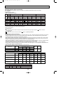
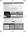
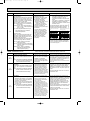
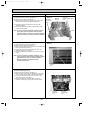
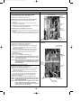
11-2. CHECK POINT UNDER TEST RUN
(MA remote controller)
(1) Before test run
• After installation of indoor and outdoor units, piping work and electric wiring work, re-check that there is no refrigerant leakage, loosened connections and incorrect polarity.
• Measure impedance between the ground and the power supply terminal block(L, N) on the outdoor unit by 500V Merger and
check that it is 1.0M" or over.
wDon’t use 500V Merger to indoor/outdoor connecting wire terminal block(S1, S2, S3) and remote controller terminal block
(1, 2). This may cause malfunction.
• Make sure that test run switch (SW4) is set to OFF before turning on power supply.
• Make sure that all of the SW5 switches for function changes on the control board of the outdoor unit are set to OFF. If all of
the SW5 switches are not set to OFF, record the settings and then set all of the switches to OFF. And perform emergency
operation. After finishing emergency operation, set the SW5 switches to the recorded settings.
• Turn on power supply twelve hours before test run in order to protect compressor.
• For specific models which requires higher ceiling settings or auto-recovery feature from power failure, make proper changes
of settings referring to the description of “Selection of Functions through Remote Controller”.
Make sure to read operation manual before test run. (Especially items to secure safety.)
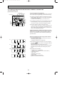
11-2-1. Test run by remote controller
Operating procedures
1. Turn on the main power supply.
CENTRALLY CONTROLLED
ON
1Hr.
OFF
˚C
CLOCK
CHECK
˚C
STAND BY
DEFROST
ERROR CODE
TEMP.
NOT AVAILABLE
FILTER
CHECK MODE
TEST RUN
FUNCTION
ON/OFF
FILTER
CHECK TEST
PAR-20MAA
TIMER SET
TEST RUN button
TEST RUN display
LIQUID PIPE TEMPERATURE display
While the room temperature display on the remote
controller is “H0”, the remote controller is disabled.
Wait until “H0” disappears before using remote controller.
“H0” appears for about 2 minutes after power supply is
turned on. w1
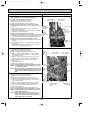
2. Press TEST RUN button twice.
The TEST RUN appears on the screen.
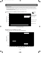
3. Press OPERATION SWITCH
button.
Cooling mode: Check if cool air blows and water is drained.
Heating mode: Check if warm air blows. (It takes a little
while until warm air blows.)
4. Press AIR DIRECTION button.
Check for correct motion of auto-vanes.
5. Check the outdoor unit fan for
correct running.
The outdoor unit features automatic capacity control to
provide optimum fan speeds. Therefore, the fan keeps
running at a low speed to meet the current outside air
condition unless it exceeds its available maximum power.
Then, in actuality, the fan may stop or run in the reverse
direction depending on the outside air, but this does not
mean malfunction.
6. Press the ON/OFF button to reset the test run in progress.
7. Turn off the main power supply.
• In case of test run, the OFF timer will be activated, and the test run will automatically stop after two hours.
• The room temperature display section shows the pipe temperature of indoor units during the test run.
• Check that all the indoor units are running properly in case of simultaneous twin and triple operation. Malfunctions may not
be displayed regardless of incorrect wiring.
w1 After turning on the power supply, the system will go into startup mode, “H0” will blink on the display section of the room
temperature, and lamp(red) of the remote controller will flash.
As to INDOOR BOARD LED, LED1 and LED2 will be lit up in case the address is 0, or turned off in case the address is not
0. LED3 will blink.
As to OUTDOOR BOARD LED, LED1(green) and LED2(red) will light up. (After the startup mode of the system finishes,
LED2(red) will be turned off.)
In case OUTDOOR BOARD LED is digital display,
— and —
will be displayed alternately every second.
• If one of the above operations doesn’t function correctly, the causes written below should be considered. Find causes from
the symptoms.
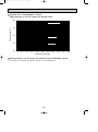
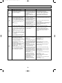
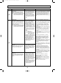
The below symptoms are under test run mode. “startup” in the table means the display status of w1 written above.
Symptoms in test run mode
OUTDOOR BOARD LED Display
Remote Controller Display
< > indicates digital display.
After “startup” is displayed, only
Remote controller displays “H0”, and
cannot be operated.
green lights up. <00>
After “startup” is displayed,
green(once) and red(once) blink
After power is turned on, “H0” is displayed alternately. <F1>
for 3 minutes, then error code is
After “startup” is displayed,
displayed.
green(once) and red(twice) blink
alternately. <F3, F4, F9>
After “startup” is displayed,
green(twice) and red(once) blink
No display appears even when remote
alternately. <EA. Eb>
controller operation switch is turned on.
After “startup” is displayed, only
(Operation lamp does not light up.)
green lights up. <00>
Display appears but soon disappears
even when remote controller is operated.
After “startup” is displayed, only
green lights up. <00>
29
Cause
• After power is turned on, “H0” is displayed for 2 minutes during
system startup. (Normal)
• Incorrect connection of outdoor terminal block (L, N and S1,
S2, S3.)
• Outdoor unit’s safeguard installation connector is open.
• Incorrect wiring between the indoor and outdoor unit (Polarity
is wrong for S1, S2, S3.)
• Remote controller transmission wire short.
• There is no outdoor unit of address 0.
(Address is other than 0.)
• Remote controller transmission wire burnout.
• After canceling function selection, operation is not possible for
about 30 seconds. (Normal)
OC294-D-1.qxp
05.3.9 11:01 AM
Page 30
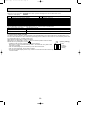
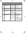
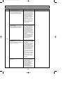
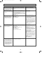
wPress the remote controller’s CHECK button twice to perform self-diagnosis. See the table below for the
contents of LCD display.
LCD
P1
P2
P4
P5
P6
P8
P9
Contents of inferior phenomena
Abnormality of room temperature thermistor
Abnormality of pipe temperature thermistor/Liquid
Abnormality of drain sensor
Drain overflow protection is working.
Freezing/overheating protection is working.
Abnormality of pipe temperature
Abnormality of pipe temperature thermistor/Cond./Eva
LCD
U1~UP
F3~F9
E0~E5
E6~EF
---FFFF
Contents of inferior phenomena
Malfunction outdoor unit
Malfunction outdoor unit
Remote controller transmitting error
Indoor/outdoor unit communication error
No error history
No applied unit
See the table below for details of the LED display (LED 1, 2, 3) on the indoor controller board.
LED1 (microcomputer power supply)
LED2 (remote controller)
Lits when power is supplied.
Remote controller
The indoor unit should be connected to the outdoor unit with address “0” setting.
LED3 (indoor/outdoor communication)
Flash when indoor and outdoor unit are communicating.
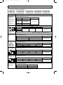
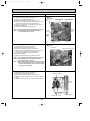
11-2-2. Test run by outdoor unit SW4
The setting of test run (ON/OFF) and its operation mode (cooling/heating) can be set by SW4 on the controller board of outdoor unit. Check that SW5-1 is set to OFF before performing test run. If SW5-1 is set to ON, turn it OFF and then perform test
run. After finishing test run, set SW5-1 back to ON.
1Set operation mode(cooling or heating) by SW4-2.
2Start test run by setting SW4-1 to ON (
) with the indicated operation mode of SW4-2.
SW4 (Factory setting)
3Finish test run by setting SW4-1 to OFF (
).
C D
• Operation mode cannot be changed by SW4-2 during test run.
A Stop
ON
Stop test run to change operation mode by SW4-1, and restart test run by SW4-1 after
B Cooling
the mode is changed.
C Operation
• Test run automatically stops 2 hours later by 2-hour OFF timer function.
D Heating
1
2
• Test run can be performed by the remote controller.
A
B
• The remote controller display of test run by outdoor unit is the same as that of test run by
remote controller.
30
OC294-D-2.qxp
05.3.9 11:03 AM
Page 31
11-3. MALFUNCTION-DIAGNOSIS METHOD BY REMOTE CONTROLLER
11-3-1. Error history of unit
(1) Wired remote controller
Mode number
ON
OFF
˚C
CLOCK
˚C
STAND BY
DEFROST
ERROR CODE
NOT AVAILABLE
TEMP.
FILTER
CHECK MODE
TEST RUN
FUNCTION
ON/OFF
FILTER
CHECK TEST
TIMER SET
PAR-20MAA
1 “CHECK” and refrigerant address are displayed at set temperature display. Error code and unit number are displayed
at clock display alternately.
(If outdoor unit is malfunctioning, unit number is 00.)
1Hr.
CENTRALLY CONTROLLED
CHECK
F
E
G
<In case of trouble during operation>
If there is a trouble on air conditioner, both indoor unit and outdoor unit will stop and digital display shows what was wrong.
Setting number
Refrigerant address
Unit number
C D
I
A
2 The refrigerant address and error code initially sent from the
unit are displayed in case of group control system which
one remote controller controls plural refrigerant systems.
J
B
3 Press the “ON/OFF” button to cancel error code.
In case of central control by the controller of MELANS, cancel the error code by the controller of the MELANS, and in
case of distant-handy combined operation, cancel the error
code by cancelling distant operation.
H
<Malfunction-diagnosis method at maintenance service>
Digital control has memory function that memorizes latest error
code even if it is cancelled by remote controller or power is
shut off, so error histories can be searched by following the
procedure below.
Search error histories of each unit by remote controller.
1 Turn to self-diagnosis mode.
Press the H “CHECK” button twice within three seconds,
and following display appears.
a) Refrigerant address for self-diagnosis
1
2 Set refrigerant address number that you want to diagnose.
Press the F
(temp.) button to set refrigerant address
to be diagnosed.
Refrigerant address has number from 00 to 15.
Three seconds after setting, lighted self-diagnosed refrigerant address begins blinking and self-diagnosis process
begins.
a)
2
3(1)
c)
b)
3 Self-diagnosis result display
(1) When there is an error history.
(Refer to 11-4. for details of error code contents.)
b) Alternating display
c) Error code
d) Attribute of error search
e) Unit number
(2) When there is no error history.
(3) When the address does not exist.
d)
e)
31
OC294-D-2.qxp
05.3.9 11:03 AM
(2)
(3)
5 (1)
b)
(2)
(3)
Page 32
4 To cancel self-diagnosis
There are following two methods to cancel self-diagnosis:
Press the H “CHECK” button twice within three seconds.
➜Self-diagnosis is cancelled and the display screen will
return to the status before self-diagnosis.
Press the I “ON/OFF” button.
➜Self-diagnosis is cancelled and indoor unit will stop.
This operation is ineffectual when the operation of remote
controller is prohibited.
During self-diagnosis at maintenance service, all the indoor
units start performing fan operation except for the indoor
unit indicating the latest error. Then outdoor units of the
same refrigerant system also start performing fan operation
intermittently for 3 minutes. (The fan is on for 3 seconds
and then off for 5 seconds.)
The unit with error can be inspected by using this. In case
unit other than indoor unit, such as outdoor unit and controller of MELANS, has an error, all the indoor units of the
same refrigerant system stop fan operation and outdoor
units operate intermittently for 3 minutes.
5 To delete error code
When something is wrong with air conditioner, error code
(P1 etc.) is memorized, but error code can be deleted after
termination of service.
<To delete error cord with remote controller>
(1) Display the error cord at the self-diagnosis result display
screen.
b) Alternating display
(2) The address for self-diagnosis will blink when the D
w button is pressed twice within three seconds.
(3) The display (3) shown on the left will be appeared when
the error cord has been reset. Note that the error content
will be redisplayed if error cord resetting is unsuccessful.
<To delete error cord with switch of outdoor unit>
Refer to 11-10. Function of switches, connectors and
jumpers.
32
OC294-D-2.qxp
05.3.9 11:03 AM
Page 33
(2) Digital wireless remote controller
<In case of trouble during operation>
When a malfunction occurs to air conditioner, both indoor unit and outdoor unit will stop and operation lamp blinks to inform
unusual stop.
<Malfunction-diagnosis method at maintenance service>
[Procedure]
1. Press the CHECK button twice.
• "CHECK" lights, and refrigerant
address "00" flashes.
• Check that the remote controller's
display has stopped before continuing.
2. Press the temperature
buttons.
• Select the refrigerant address of the
indoor unit for the self-diagnosis.
Note: Set refrigerant address using the
outdoor unit’s DIP switch (SW1).
(For more information, see the
outdoor unit installation manual.)
Refrigerant
address
display
Temperature
button
TEMP
ON/OFF
ON/OFF
button
AUTO STOP
VANE
AUTO START
CHECK LOUVER
CHECK
button
min
TEST RUN
SET
h
RESET
CLOCK
HOUR
button
3. Point the remote controller at the • If an air conditioner error occurs, the
sensor on the indoor unit and
indoor unit's sensor emits an intermitpress the HOUR button.
tent buzzer sound, the operation light
flashes, and the error code is
output.
(It takes 3 seconds at most for error
code to appear.)
4. Point the remote controller at the • The check mode is cancelled.
sensor on the indoor unit and
press the ON/OFF button.
✽ Malfunction diagnosis can be performed only for refrigerant system controlling wireless units.
Inspected unit Error code Beep output Operation LED Inspected unit Check code Beep output Operation LED
Indoor unit
MODE
FAN
P1
beep O 1 time 1 sec. O 1 time
P2
beep O 2 times 1 sec.O 2 times
P4
beep O 4 times 1 sec.O 4 times
P5
beep O 5 times 1 sec.O 5 times
P6
beep O 6 times 1 sec.O 6 times
P8
beep O 8 times 1 sec.O 8 times
P9
beep O 2 times 1 sec.O 2 times
E4, E5
Other than above Other than above
33
Outdoor
unit
CHECK
CHECK
display
F1–F9
U0–UP
E6–EE
beep beep O 1 time
(0.4sec+0.4sec)
O 1 time
Other than above Other than above
No check code
No output
(normal)
No check code
(mistake of matching with refrigerant beep beep beep
address)
Lights off
Lights off
OC294-D-2.qxp
05.3.9 11:03 AM
Page 34
11-3-2. Wired Remote controller Diagnosis
If operation can not be carried out from remote controller, try
remote controller diagnosis with following process.
1
a)
1 First, check the electricity current marker.
When correct voltage (DC12V) is not supplied to remote
controller, the electricity current marker is put out.
If the electricity current marker is not lighted, check the
remote controller wiring and the indoor units.
a) Electric current marker
2 Transfer to remote controller diagnosis mode
Hold down the H “CHECK” button for five seconds or more,
and following display appears.
Press the A “FILTER” button, and remote controller diagnosis will begin.
2
3 Remote controller diagnosis result
(1) When the remote controller is functioning correctly
Check other possible causes, as there is no problem
with remote controller.
Consider the unit is normal when remote controller transmits the result of diagnosis to indoor or outdoor unit and
receives the same data back.
(2) When remote controller has malfunction
The remote controller must be replaced.
If the transmitting-receiving circuit is defective, [‘NG’]
blinks.
"NG" will be displayed when remote controller transmits
the result of diagnosis to indoor or outdoor unit, and
receives no response.
3(1)
(2)
When there might be other problems than diagnosed remote
controller,
(3)
(4)
b)
(3) There might be noise on transmission path or damage of
other remote controllers or indoor units. Check the transmission path and other controllers.
If the transmission is not possible, [E3] blinks.
"E3" will be displayed when remote controller transmits
the result of diagnosis to indoor or outdoor unit and
receives different data back.
(4) The number of data errors means the difference
between the number of bits sent from remote controller
and the actual number of bits sent to transmission path.
If the data error is displayed, noise and etc. are interfering with the transmission data. Check the transmission
path.
If the data error has occurred, [ERC] and number of data
errors are displayed.
b) Number of generated data errors (maximum 66 errors)
When the number of data errors is 02.
Transmission data from remote controller
Transmission data on transmission path
4 Cancel the remote controller diagnosis
Hold down the H “CHECK” button for five seconds or more
to cancel remote controller diagnosis, then [H0] operation
lamp will blink and the display screen will return to the status before remote controller diagnosis in about 30 seconds.
34
OC294-D-2.qxp
05.3.9 11:03 AM
Page 35
11-4. SELF-DIAGNOSIS ACTION TABLE
<Abnormalities detected when the power is put on>
(Note 1) Refer to indoor unit section for code P and code E.
Error Code Meaning of error code and detection method
None
—
Case
Judgment and action
1 No voltage is supplied to terminal 1 Check following items.
block(TB1) of outdoor unit.
a) Power supply breaker
a) Power supply breaker is put
b) Connection of power supply terminal block.
off.
(TB1)
b) Contact failure or disconc) Connection of power supply terminal block.
nection of power supply
(TB1)
terminal
c) Open phase (L or N phase) 2 Check following items.
a) Connection of power supply terminal block.
2 Electric power is not charged
to power supply terminal of
(TB1)
outdoor power circuit board.
b) Connection of terminal on outdoor power
a) Contact failure of power
circuit board.
RP1.6-3V :Disconnection of connector R or S.
supply terminal
Refer to page 59.
b) Open phase on the outdoor
RP4V-6V :Disconnection of connector SC-R
power circuit board
or SC-S. Refer to page 60.
RP1.6-3V :Disconnection of
connector R or S
3 Check connection of the connector (CNDC)
RP4V~6V :Disconnection of
on the outdoor controller circuit board.
connector SC-R or SC-S
Check connection of the connector, LD1 and
3 Electric power is not supplied to
LD2 for RP1.6-3V and CNDC for RP4-6V, on
outdoor controller circuit board.
the outdoor power circuit board.
a) Disconnection of connector
Refer to page 53, 59 and 60.
(CNDC)
.
4 Check connection of reactor. (DCL or ACL)
RP1.6-3V: Check connection of “LO” and
4 Disconnection of reactor (DCL
“NO” on the outdoor noise filter circuit board.
or ACL)
Check connection of “R” and “S” on the
outdoor power circuit board.
5 Disconnection of outdoor noise
Refer to page 55, 56 and 59.
filter circuit board or parts failure
RP4-6V: Check connection of “L1” and “L2”
in outdoor noise filter circuit
on the active filter module.(ACTM)
board
6 Defective outdoor power circuit 5 a) Check connection of outdoor noise filter
circuit board.
board
b) Replace outdoor noise filter circuit board.
7 Defective outdoor controller
Refer to page 55, 56 and 59.
circuit board
6 Replace outdoor power circuit board.
7 Replace controller board (When items above
are checked but the units can not be repaired.)
F3
(5202)
63L connector open
Abnormal if 63L connector circuit is open
for three minutes continuously after power
supply.
63L: Low-pressure switch
<PUHZ-RP4-6VHA, RP4-6YHA only>
F5
(5201)
F9
(4119)
63H connector open
Abnormal if 63H connector circuit is open
for three minutes continuously after power
supply.
63H: High-pressure switch
1 Disconnection or contact failure 1 Check connection of 63L connector on
of 63L connector on outdoor
outdoor controller circuit board.
controller circuit board
Refer to 11-9.
2 Disconnection or contact failure 2 Check the 63L side of connecting wire.
of 63L
3 63L is working due to refriger- 3 Check refrigerant pressure.
ant leakage or defective parts.
Charge additional refrigerant.
Check continuity by tester.
4 Defective outdoor controller
circuit board
Replace the parts if the parts are defective.
4 Replace outdoor controller circuit board.
1 Disconnection or contact failure
of 63H connector on outdoor
controller circuit board
2 Disconnection or contact failure
of 63H
3 63H is working due to defective
parts.
4 Defective outdoor controller
circuit board
2 connector open
1 Disconnection or contact failure
Abnormal if both 63H and 63L connector
of connector (63H,63L) on
circuits are open for three minutes continuoutdoor controller circuit board.
ously after power supply.
2 Disconnection or contact failure
of 63H, 63L
63H: High-pressure switch
3 63H and 63L are working due
63L: Low-pressure switch
to defective parts.
4 Defective outdoor controller
<PUHZ-RP4-6VHA, RP4-6YHA only>
board.
35
1 Check connection of 63H connector on
outdoor controller circuit board.
Refer to 11-9.
2 Check the 63H side of connecting wire.
3 Check continuity by tester.
Replace the parts if the parts are defective.
4 Replace outdoor controller circuit board.
1 Check connection of connector(63H,63L) on
outdoor controller circuit board.
Refer to 11-9.
2 Check the 63H and 63L side of connecting
wire.
3 Check continuity by tester.
Replace the parts if the parts are defective.
4 Replace outdoor controller circuit board.
OC294-D-2.qxp
05.3.9 11:03 AM
Page 36
Error Code Meaning of error code and detection method
Indoor/outdoor unit connector
mis-wiring, excessive number of units
(4 units or more)
1. Outdoor controller circuit board can
automatically check the number of
connected indoor units. Abnormal if the
number cannot be checked automatically
due to mis-wiring of indoor/outdoor unit
connecting wire and etc. after power is
turned on for 4 minutes.
EA
2. Abnormal if outdoor controller circuit
(6844)
board recognizes the number of
connected indoor units as “4 units or
more”.
Eb
(6845)
EC
(6846)
Case
1 Contact failure or mis-wiring of
indoor/outdoor unit connecting
wire
2 Diameter or length of
indoor/outdoor unit connecting
wire is out of specified capacity.
3 4 or more indoor units are
connected to one outdoor unit.
4 Defective transmitting receiving
circuit of outdoor controller
circuit board
5 Defective transmitting receiving
circuit of indoor controller
board
6 Defective indoor power board
7 Two or more outdoor units
have refrigerant address “0” .
(In case of group control)
8 Noise has entered into power
supply or indoor / outdoor unit
connecting wire.
Judgment and action
1 Check disconnection or looseness or polarity
of indoor/outdoor unit connecting wire of
indoor and outdoor units.
2 Check diameter and length of indoor/outdoor
unit connecting wire.
Total wiring length: 80m
(including wiring connecting each indoor unit
and between indoor and outdoor unit)
Also check if the connection order of flat
cable is S1, S2, S3.
3 Check the number of indoor units that are
connected to one outdoor unit. (If EA is
detected)
4~6 Put the power off once, and on again to
check.
Replace outdoor controller circuit board,
indoor controller board or indoor power
board if abnormality occurs again.
Mis-wiring of indoor/outdoor unit
connecting wire (converse wiring or
disconnection)
Outdoor controller circuit board can
automatically set the unit number of indoor
units.
Abnormal if the indoor unit number can
not be set within four minutes after power
on because of mis-wiring (converse wiring
or disconnection) of indoor/outdoor unit
connecting wire.
1 Contact failure or mis-wiring of
7 Check if refrigerant addresses (SW1-3 to
indoor/outdoor unit connecting
SW1-6 on outdoor controller circuit board)
wire
are overlapping in case of group control
2 Diameter or length of
system.
indoor/outdoor unit connecting
wire is out of specified capacity.
8 Check transmission path, and remove the
4 Defective transmitting receiving
cause.
circuit of outdoor controller circuit
board.
w The descriptions above, 1-8, are for EA, Eb
5 Defective transmitting receiving
and EC.
circuit of indoor controller board
6 Defective indoor power board.
7 Two or more outdoor units
have refrigerant address “0” .
(In case of group control)
8 Noise has entered into power
supply or indoor/outdoor unit
connecting wire.
Start-up time over
The unit can not finish start-up process
within four minutes after power on.
1 Contact failure of indoor/
outdoor unit connecting wire
2 Diameter or length of indoor/
outdoor unit connecting wire is
out of specified capacity.
7 Two or more outdoor units
have refrigerant address “0” .
(In case of group control)
8 Noise has entered into power
supply or indoor/outdoor unit
connecting wire.
36
OC294-D-2.qxp
05.3.9 11:03 AM
Page 37
<Abnormalities detected while unit is operating>
Error Code Meaning of error code and detection method
Abnormal high pressure (High-pressure
switch 63H worked)
Abnormal if high-pressure switch 63H
worked ( w ) during compressor operation.
w RP1.6-2VHA : 4.15 MPa
RP2.5-6VHA : 4.41 MPa
RP2.5-6VHA1 : 4.15 MPa
RP4-6YHA
: 4.15 MPa
63H: High-pressure switch
U1
(1302)
Abnormal high discharging temperature
(1) Abnormal if discharge temperature
thermistor (TH4) exceeds 125: or
110: continuously for 5 minutes.
Abnormal if condenser/evaporator
temperature thermistor (TH5) exceeds
40: during defrosting and discharge
temperature thermistor (TH4) exceeds
110:.
U2
(1102)
Case
1 Short cycle of indoor unit
2 Clogged filter of indoor unit
3 Decreased airflow caused by
dirt of indoor fan
4 Dirt of indoor heat exchanger
5 Locked indoor fan motor
6 Malfunction of indoor fan motor
7 Defective operation of stop
valve (Not full open)
8 Clogged or broken pipe
9 Locked outdoor fan motor
0 Malfunction of outdoor fan
motor
1 Short cycle of outdoor unit
2 Dirt of outdoor heat exchanger
3 Decreased airflow caused by
defective inspection of outside
temperature thermistor
(It detects lower temperature
than actual temperature.)
4 Disconnection or contact failure
of connector (63H) on outdoor
controller board
5 Disconnection or contact failure
of 63H connection
6 Defective outdoor controller
board
7 Defective action of linear
expansion valve
8 Malfunction of fan driving
circuit
1 Over-heated compressor operation caused by shortage of
refrigerant
2 Defective operation of stop
valve
3 Defective thermistor
4 Defective outdoor controller
board
5 Defective action of linear
expansion valve
(2) Abnormal if discharge super heat
(Cooling: TH4 – TH5 / Heating: TH4 –
TH6) increases.
All the conditions in A or B are detected
simultaneously for 10 minutes
continuously after 6 minutes past from
compressor start-up (including the
thermostat indication or recovery from
defrosting).
<Condition A>
• Heating mode
• When discharge super heat is less
than 70 deg.
• When the TH6 temp is more than the
value obtained by TH7 – 5 deg.
• When the condensing temp of TH5 is
less than 35:.
<Condition B>
• During comp operation (Cooling and
Heating)
• When discharge super heat is less
than 80 deg in Cooling.
• When discharge super heat is less
than 90 deg in Heating.
• When condensing temp of TH6 is
more than –40:. (In Cooling only.)
37
Judgment and action
1~6Check indoor unit and repair defectives.
7 Check if stop valve is full open.
8 Check piping and repair defectives.
9~2 Check outdoor unit and repair defectives.
3 Check the inspected temperature of outside
temperature thermistor on LED display.
(SW2 on A-Control Service Tool : Refer to
page 68.)
4~6Put the power off and check F5 is
displayed when the power is put again.
When F5 is displayed, refer to “Judgment
and action” for F5.
7 Check linear expansion valve.
Refer to 11-6.
8 Replace outdoor controller board.
1 Check intake super heat.
Check leakage of refrigerant.
Charge additional refrigerant.
2 Check if stop valve is full open.
34 Put the power off and check if U3 is displayed when the power is put again.
When U3 is displayed, refer to “Judgement
and action” for U3.
5 Check linear expansion valve.
Refer to 11-6.
OC294-D-2.qxp
05.3.9 11:03 AM
Page 38
Judgment and action
Case
Error Code Meaning of error code and detection method
Open/short circuit of discharge
1 Disconnection or contact
temperature thermistor (TH4)
failure of connector (TH4) on
the outdoor controller circuit
Abnormal if open (3: or less) or short
board.
(217: or more) is detected during
U3
compressor operation.
2 Defective thermistor
(5104)
(Detection is inoperative for 10 minutes of 3 Defective outdoor controller
compressor starting process and for 10
circuit board
minutes after and during defrosting.)
Open/short of outdoor unit thermistors
(TH3, TH6, TH7, and TH8)
Abnormal if open or short is detected
during compressor operation.
Open detection of thermistors TH3 and
TH6 is inoperative for 10 seconds to 10
minutes after compressor starting and 10
minutes after and during defrosting.
WCheck which unit has abnormality in its
thermistor by switching the mode of
U4
SW2.
(TH3:5105)
(Refer to page 73.)
(TH6:5107)
(TH7:5106)
(TH8:5110)
Symbol
TH3
TH6
TH7
TH8
TH8
U5
(4230)
1 Disconnection or contact failure 1 Check connection of connector (TH3,TH6/TH7)
of connectors
on the outdoor controller circuit board.
Check connection of connector (CN3) on the
Outdoor controller circuit
outdoor power circuit board.
board: TH3,TH6/TH7
Check breaking of the lead wire for thermistor
Outdoor power circuit board:
(TH3,TH6,TH7,TH8). Refer to page 53, 59 and 60.
CN3
2 Check resistance value of thermistor
2 Defective thermistor
(TH3,TH6,TH7,TH8) or check temperature by
3 Defective outdoor controller
microcomputer.
circuit board
(Thermistor/TH3,TH6,TH7,TH8: Refer to page 47.)
(SW2 on A-Control Service Tool: Refer to
page 68.)
3 Replace outdoor controller circuit board.
WEmergency operation is available in case of
abnormalities of TH3, TH6 and TH7.
Refer to 11-8.
)
(
Thermistors
Name
Thermistor <Outdoor pipe>
Thermistor <Outdoor 2-phase pipe>
Thermistor <Outdoor>
Thermistor <Heat sink> RP1.6-6VHA
Internal thermistor RP4-6YHA
Abnormal temperature of heat sink
Abnormal if heat sink thermistor(TH8)
detects temperature indicated below.
RP1.6V, 2VHA·······84:
RP2.5V, 3VHA·······77:
RP4-6VHA·············85:
RP4-6YHA·············95:
1 Check connection of connector (TH4) on the
outdoor controller circuit board.
Check breaking of the lead wire for
thermistor (TH4). Refer to 11-9.
2 Check resistance value of thermistor (TH4) or
temperature by microcomputer.
(Thermistor/TH4: Refer to 11-6.)
(SW2 on A-Control Service Tool: Refer to
page 68.)
3 Replace outdoor controller board.
Open detection
Short detection
– 40: or below
– 40: or below
– 40: or below
– 27: or below
– 35: or below
90: or above
90: or above
90: or above
102: or above
170: or above
1 The outdoor fan motor is
locked.
2 Failure of outdoor fan motor
3 Air flow path is clogged.
4 Rise of ambient temperature
5 Defective thermistor
6 Defective input circuit of
outdoor power circuit board
7 Failure of outdoor fan drive
circuit
38
12 Check outdoor fan.
Refer to (9) in “12-2 Trouble shooting by
inferior phenomena ” on Service Technical
Guide for OCT04.
3 Check air flow path for cooling.
4 Check if there is something which causes
temperature rise around outdoor unit.
(Upper limit of ambient temperature is 46:.)
Turn off power, and on again to check if U5
is displayed within 30 minutes.
If U4 is displayed instead of U5, follow the
action to be taken for U4.
5 Check resistance value of thermistor (TH8)
or temperature by microcomputer.
(Thermistor/TH8: Refer to 11-6.)
(SW2 on A-Control Service Tool: Refer to
page 68.)
6 Replace outdoor power circuit board.
7 Replace outdoor controller circuit board.
OC294-D-2.qxp
05.3.9 11:03 AM
Page 39
Case
Error Code Meaning of error code and detection method
Abnormality of power module
1 Outdoor stop valve is closed.
Check abnormality by driving power module 2 Decrease of power supply voltage
in case overcurrent is detected.
3 Looseness, disconnection or
(UF or UP error condition)
converse of compressor wiring
U6
connection
(4250)
4 Defective compressor
5 Defective outdoor power circuit
board
U7
(1520)
U8
(4400)
Abnormality of super heat due to low
discharge temperature (RP1.6-3VHA)
Abnormal if discharge super heat is
continuously detected less than or equal
to 0: for 3 minutes even though linear
expansion valve has minimum open pulse
after compressor starts operating for 10
minutes.
(RP1.6-3VHA only)
1 Disconnection or loose
connection of discharge
temperature thermistor. (TH4)
2 Defective holder of discharge
temperature thermistor.
3 Disconnection or loose connection
of linear expansion valve’s coil.
4 Disconnection or loose
connection of linear expansion
valve’s connector.
5 Defective linear expansion valve.
4 Check compressor referring to 11-6.
5 Replace outdoor power circuit board.
12 Check the installation conditions of
discharge temperature thermistor (TH4).
3 Check the coil of linear expansion valve.
Refer to page 51.
4 Check the connection or contact of LEV-A and
LEV-B on outdoor controller circuit board.
5 Check linear expansion valve.
Refer to 11-6.
Abnormality in the outdoor fan motor
1 Failure in the operation of
(RP4-6YHA only)
the DC fan motor
The outdoor fan motor is considered to be 2 Failure in the outdoor circuit
abnormal if the rotational frequency of fan
controller board
motor is abnormal when detected during
operation.
Fan motor rotational frequency is abnormal if;
• 100 rpm or below detected continuously
for 15 seconds at 20: or more outside
air temperature
• 50 rpm or below or 1500 rpm or more
detected continuously for 1 minute.
1 Check or replace the DC fan motor.
2 Check the voltage of the outdoor circuit
controller board during operation.
3 Replace the outdoor circuit controller
board. (when the failure is still indicated
even after performing the remedy 1
above.)
1 Decrease of power supply voltage
2 Disconnection of compressor
wiring
3 Defective 52C
Abnormal if any of followings are detected 4 Disconnection or loose connecduring compressor operation;
tion of CN52C (RP1.6-3VHA only)
• Decrease of DC bus voltage to 310V
5 Defective PFC module of outdoor
(RP1.6-6VHA only)
power board (RP1.6-3VHA only)
• Instantaneous decrease of DC bus voltage 6 Defective ACT module (RP4RP1.6-6VHA : 200V, RP4-6YHA : 350V
6VHA only)
• Increase of DC bus voltage to
7 Defective ACT module drive
RP1.6-3VHA : 420V
RP4-6VHA : 400V
circuit of outdoor power circuit
RP4-6YHA : 760V
board (RP4-6VHA only)
• Decrease of input current of outdoor unit 8 Disconnection or loose connecto 0.5A only if operation frequency is more
tion of CNAF (RP4-6VHA only)
than or equal to 40Hz or compressor
9 Defective outdoor converter
current is more than or equal to 5A.
circuit board (RP4-6YHA only)
0 Defective 52C drive circuit of
outdoor controller circuit board
(RP1.6-6VHA)
1 Disconnection or loose
connection of CN5 on the
outdoor power circuit board.
2 Defective 52C drive circuit of
outdoor power circuit board.
(RP4-6YHA only)
3 Disconnection or loose
connection of CN2 on the
outdoor power circuit board.
1 Check the facility of power supply.
2 Correct the wiring (U•V•W phase) to compressor.
Refer to page 59 and 60.
3 Replace 52C.
4 Check CN52C wiring.
Abnormality such as overvoltage or
voltage shortage and abnormal
synchronous signal to main circuit
U9
(4220)
Judgment and action
1 Open stop valve.
2 Check facility of power supply.
3 Correct the wiring (U•V•W phase) to
compressor. Refer to page 59 and 60.
39
5 Replace outdoor power circuit board.
(RP1.6-3VHA only)
6 Replace ACT module. (RP4-6VHA only)
7 Replace outdoor power circuit board.
(RP4-6VHA only)
8 Check CNAF wiring. (RP4-6VHA only)
9 Replace outdoor converter circuit board.
(RP4-6YHA only)
0 Replace outdoor controller circuit board.
(RP1.6-6VHA only)
1 Check CN5 wiring on the outdoor power
circuit board.
Refer to page 59 and 60.
2 Replace outdoor power circuit board.
(RP4-6YHA only)
3 Check CN2 wiring on the outdoor power
circuit board.
Refer to page 59 and 60.
OC294-D-2.qxp
05.3.9 11:03 AM
Page 40
Error Code Meaning of error code and detection method
UF
(4100)
Compressor overcurrent interruption
(When compressor locked)
Abnormal if overcurrent of DC bus or
compressor is detected within 30 seconds
after compressor starts operating.
Case
Judgment and action
1 Open stop valve.
2 Check facility of power supply.
1 Stop valve is closed.
2 Decrease of power supply
voltage
3 Correct the wiring (U•V•W phase) to
3 Looseness, disconnection or
compressor.
converse of compressor wiring
Refer to page 59 and 60.
connection
4 Check compressor.
4 Defective compressor
Refer to 11-6.
5 Defective outdoor power board
5 Replace outdoor power circuit board.
UH
(5300)
Current sensor error
1 Disconnection of compressor
Abnormal if current sensor detects –1.5A to
wiring
1.5A during compressor operation. (This
2 Defective circuit of current
error is ignored in case of test run mode.)
sensor on outdoor power
circuit board
Abnormal low pressure (63L worked)
Abnormal if 63L is worked (under0.03MPa) during compressor operation.
63L: Low-pressure switch
UL
(1300)
UP
(4210)
(RP4-6VHA, RP4-6YHA)
1 Stop valve of outdoor unit is
closed during operation.
2 Disconnection or loose connection
of connector (63L) on outdoor
controller board
3 Disconnection or loose
connection of 63L
4 Defective outdoor controller board
5 Leakage or shortage of refrigerant
6 Malfunction of linear expansion
valve
Compressor overcurrent interruption
1 Stop valve of outdoor unit is
Abnormal if overcurrent DC dc bus or comclosed.
pressor is detected after compressor starts 2 Decrease of power supply voltoperating for 30 seconds.
age
3 Looseness, disconnection or
converse of compressor wiring
connection
4 Defective fan of indoor/outdoor
units
5 Short cycle of indoor/outdoor
units
6 Defective input circuit of outdoor controller board
7 Defective compressor
40
1 Correct the wiring (U•V•W phase) to
compressor. Refer to page 59 and 60.
2 Replace outdoor power circuit board.
1 Check stop valve.
2~4 Put the power off and on again to check
if F3 is displayed on restarting.
If F3 is displayed, follow the F3 processing
direction.
5 Correct to proper amount of refrigerant.
6 Check linear expansion valve.
Refer to 11-6.
1 Open stop valve.
2 Check facility of power supply.
3 Correct the wiring (U•V•W phase) to
compressor. Refer to page 59 and 60.
4 Check indoor/outdoor fan.
5 Solve short cycle.
6 Replace outdoor controller circuit board.
7 Check compressor.
Refer to 11-6.
W Before the replacement of the outdoor
controller circuit board, disconnect the wiring
to compressor from the outdoor power circuit
board and check the output voltage among
phases, U, V, W, during test run. No defect
on board if voltage among phases (U-V, V-W
and W-U) is same. Make sure to perform the
voltage check with same performing frequency.
OC294-D-2.qxp
05.3.9 11:03 AM
Page 41
Case
Error Code Meaning of error code and detection method
Remote controller communication error 1 Defective communication cir(Signal receiving error)
cuit of remote controller
(1) Abnormal if any signal from IC of refrig- 2 Defective communication cirerant address “0” could not be normally
cuit of indoor controller board
received for three minutes.
of refrigerant address “0”
(2) Abnormal if sub remote controller could 3 Noise has entered into transE0
not receive any signal for two minutes.
mission line of remote con(No display)
troller.
4 All remote controllers are set
as “sub” remote controller. In
this case, E4 is displayed at
outdoor LED, and E0 is displayed at remote controller.
Remote controller communication error 1 Defective communication cir(Transmitting error)
cuit of remote controller
(1) Abnormal if sub remote controller could 2 Noise has entered into transnot find blank of transmission path for
mission line of remote conE3
six seconds.
troller.
(No display) (2) Abnormal if remote controller could not
3 Two remote controllers are set
finish transmitting 30 times continuousas "main."
ly.
(In case of 2 remote controllers)
E8
(6840)
E9
(6841)
EF
(6607
or
6608)
Judgment and action
1~3 Diagnose remote controller.
Take actions as follows according to
diagnosis result.
a) When “RC OK” is displayed,
remote controllers have no problem.
Put the power off, and on again to
check. If, “H0” is displayed for four
minutes or more, replace indoor controller board.
b) When “RC NG” is displayed,
replace remote controller.
c) When “RC E3” or “ERC 00-66” is displayed, noise may be causing abnormality.
4 Set a remote controller to main, and the
other to sub.
w The descriptions above, 1-3, are for E0 and
E3.
Indoor/outdoor unit communication
error (Signal receiving error)
(Outdoor unit)
(1) Abnormal if outdoor controller circuit
board could not receive anything
normally for three minutes.
1 Contact failure of indoor/out1 Check disconnection or looseness of indoor/
door unit connecting wire.
outdoor unit connecting wire of indoor or outdoor units.
2 Defective communication circuit
of outdoor controller circuit board. 2~4 Put the power off, and on again to check.
Replace indoor controller board or outdoor
3 Defective communication circuit of indoor controller board
controller circuit board if abnormality is
displayed again.
4 Noise has entered into indoor/
outdoor unit connecting wire.
Indoor/outdoor unit communication
error (Transmitting error) (Outdoor unit)
(1) Abnormal if “0” receiving is detected 30
times continuously though outdoor controller circuit board has transmitted “1”.
(2) Abnormal if outdoor controller circuit
board could not find blank of transmission
path for three minutes.
1 Indoor/ outdoor unit connecting 1 Check disconnection or looseness of
wire has contact failure.
indoor/outdoor unit connecting wire.
2 Defective communication circuit 2~4 Put the power off, and on again to check.
of outdoor controller circuit board.
Replace outdoor controller circuit board if
3 Noise has entered power supply.
abnormality is displayed again.
4 Noise has entered indoor/ outdoor unit connecting wire.
Non defined error code
This code is displayed when non defined
error code is received.
1 Noise has entered transmission wire of remote controller.
2 Noise has entered indoor/ outdoor unit connecting wire.
3 Outdoor unit is not a series of
power-inverter.
4 Model name of remote controller is PAR-S25A.
Serial communication error
1.Abnormal if serial communication
between outdoor controller circuit
board and outdoor power circuit board
is defective.
12 Check connection of each connector CN2
1 Breaking of wire or contact
and CN4 between the outdoor controller
failure of connector CN2
circuit board and the outdoor power circuit
between the outdoor controller
board.
circuit board and the outdoor
power circuit board.
2 Breaking of wire or contact
failure of connector CN4
3 Replace outdoor power circuit board.
between the outdoor controller
circuit board and the outdoor
4 Replace outdoor controller circuit board.
power circuit board.
3 Defective communication circuit
of outdoor power circuit board
4 Defective communication circuit
of outdoor controller circuit board
for outdoor power circuit board
2. Abnormal if communication between
outdoor controller circuit board and
M-NET board is not available.
1 Breaking of wire or contact
1 Check disconnection, looseness, or breaking of
connection wire between outdoor controller cirfailure of connector between
cuit board (CNMNT) and M-NET board (CN5).
outdoor controller circuit board
2 Check disconnection, looseness, or breaking of
and M-NET board
connection wire between outdoor controller cir2 Contact failure of M-NET board
cuit board(CNMNT) and M-NET board (CND).
power supply line
3 Refer to (4) in “ 2-2. M-NET Wiring method ”
3 Noise has entered into M-NET
on Service Technical Guide for OCT04.
transmission wire.
Ed
(0403)
41
12 Put the power off, and on again to check.
Replace indoor controller board or outdoor
controller circuit board if abnormality is
displayed again.
3 Replace outdoor unit with power-inverter type
outdoor unit.
4 Replace remote controller with MA remote
controller.
OC294-D-2.qxp
05.3.9 11:03 AM
Page 42
Error Code Meaning of error code and detection method
P8
Abnormality of pipe temperature
1 Slight temperature difference
<Cooling mode>
between indoor room
Detected as abnormal when the pipe temtemperature and pipe <liquid
perature is not in the cooling range 3 minor condenser / evaporator>
utes later of compressor start and 6 mintemperature thermistor
utes later of the liquid or condenser/evapo• Shortage of refrigerant
rator pipe is out of cooling range.
• Disconnected holder of pipe
Note 1) It takes at least 9 min. to detect.
<liquid or condenser /
Note 2) Abnormality P8 is not detected in
evaporator> thermistor
drying mode.
• Defective refrigerant circuit
Cooling range : Indoor pipe temperature
2 Converse connection of
(TH2 or TH5) – intake temperature
extension pipe (on plural units
(TH1) [ -3 deg
connection)
TH: Lower temperature between: liquid
3 Converse wiring of indoor/
pipe temperature and condenser/
outdoor unit connecting wire
evaporator temperature
(on plural units connection)
4 Defective detection of indoor
<Heating mode>
room temperature and pipe
When 10 seconds have passed after the
<condenser / evaporator>
compressor starts operation and the hot
temperature thermistor
adjustment mode has finished, the unit is
5 Stop valve is not opened
detected as abnormal when
completely.
condenser/evaporator pipe temperature is
not in heating range within 20 minutes.
Note 3) It takes at least 27 minutes to
detect abnormality.
Note 4) It excludes the period of defrosting
(Detection restarts when defrosting
mode is over)
Heating range : 3 deg [ (Condenser/
Evaporator temperature(TH5) –
intake temperature(TH1))
<M-NET communication error>
A2
(6602)
A3
(6603)
1~4
(
Check pipe <liquid or condenser /
evaporator> temperature with room
temperature display on remote
controller and outdoor controller circuit
board.
Pipe <liquid or condenser / evaporator>
temperature display is indicated by
setting SW2 of outdoor controller circuit
board as follows.
Conduct temperature check with outdoor
controller circuit board after connecting
‘A-Control Service Tool(PAC-SK52ST)’.
)
Temperature display of indoor liquid pipe
Indoor 1
1
2
3
4
5
6
Temperature display of indoor condenser/
evaporator pipe Indoor 1
1
2
3
4
5
6
ON
ON
OFF
OFF
Temperature display of indoor liquid pipe
Indoor 2
1
2
3
4
5
6
Temperature display of indoor condenser/
evaporator pipe Indoor 2
1
2
3
4
5
6
ON
ON
OFF
OFF
A-Control Service Tool
SW2 setting
23Check converse connection of extension
pipe or converse wiring of indoor/outdoor
unit connecting wire.
(Note) “Indoor unit” in the text indicates M-NET board in outdoor unit.
Error Code Meaning of error code and detection method
Case
Address duplicate definition
1 There are two or more same
This error is displayed when transmission
address of controller of outfrom the units of same address is detectdoor unit, indoor unit, FRESH
A0
ed.
MASTER, or LOSSNAY.
(6600)
Note) The address and attribute displayed 2 Noise has entered into transat remote controller indicate the conmission signal and signal was
troller that detected abnormality.
transformed.
Hard ware error of transmission
processor
Transmission processor intended to transmit “0”, but “1” appeared on transmission
wire.
Note) The address and attribute display at
remote controller indicate the controller that detected abnormality.
Judgment and action
Case
1 Error is detected if wave form is
transformed when wiring works of
transmission wire of outdoor unit,
indoor unit, FRESH MASTER or
LOSSNAY are done, or polarity is
changed with the power on and
transmission data collide each other.
2 Defective transmitting receiving
circuit of transmission processor
3 Transmission data is changed by
the noise on transmission.
BUS BUSY
1 Transmission processor could
not transmit because short cycle
1. Over error by collision damage
voltage of noise and the like
Abnormal if transmitting is not possible
have entered into transmission
for 8-10 minutes continuously because
wire continuously.
of collision of transmission.
2. Data could not reach transmission wire 2 Transmission quantity has
increased and transmission is
for 8-10 minutes continuously because
not possible because there was
of noise or etc.
wiring mistake of terminal block
Note) The address and attribute displayed
for transmission wire (TB3) and
at remote controller indicate the conterminal block for central control
troller that detected abnormality.
(TB7) in outdoor unit.
3 Transmission are mixed with
others and occupation rate on
transmission wire rose because
of defective repeater (a function
to connector or disconnect transmission of control and central
control system) of outdoor unit,
then abnormality is detected.
42
Judgment and action
Search the unit with same address as abnormality
occurred. If the same address is found, shut of the
power supply of outdoor unit and indoor unit and
FRESH MASTER or LOSSNAY at the same time
for two minutes or more after the address is corrected, and put the power on again.
Check transmission wave form or noise on transmission wire.
1 If the works of transmission wire is done with
the power on, shut off the power supply of
outdoor unit and indoor unit and FRESH
MASTER or LOSSNAY at the same time for
two minutes or more, and put the power on
again.
2 Check transmission wave form or noise on
transmission wire.
1 Check if transmission wire of indoor unit,
FRESH MASTER, LOSSNAY, or remote controller is not connected to terminal block for
central control (TB7) of outdoor unit.
2 Check if transmission wore of indoor unit,
FRESH MASTER or LOSSNAY is not connected to terminal block for transmission
wire of outdoor unit.
3 Check if terminal block for transmission wire
(TB3) and terminal block for central control
(TB7) is not connected.
4 Check transmission wave form or noise on
transmission wire.
OC294-D-2.qxp
05.3.9 11:03 AM
Page 43
Error Code Meaning of error code and detection method
A6
(6606)
Case
Judgment and action
Communication error with communication processor
Defective communication between unit
processor and transmission processor
Note) The address and attribute display at
remote controller indicate the controller that detected abnormality.
1 Data of transmission processor or unit processor is not
transmitted normally because
of accidental trouble such as
noise or thunder surge.
2 Address forwarding from unit
processor is not transmitted
normally because of defective
transmission processor hardware.
Shut of the power supply of outdoor unit and
indoor unit and FRESH MASTER or LOSSNAY
at the same time for two minutes or more, and
put the power on again. System returns normally if abnormality was accidental malfunction.
If the same abnormality generates again,
abnormality-generated controller may be defective.
NO ACK signal
1. Transmitting side controller detects
abnormal if a massage was transmitted
but there is no reply (ACK) that a massage was received. Transmitting side
detects abnormality every 30 seconds,
six times continuously.
Note) The address and attribute displayed
at remote controller is indicate the
controller that did not reply (ACK).
Common factor that has no relation with abnormality source.
1 The unit of former address
does not exist as address
switch has changed while the
unit was energized.
2 Extinction of transmission wire
voltage and signal is caused by
over-range transmission wire.
• Maximum distance ······200m
• Remote controller line ··(12m)
3 Extinction of transmission wire
voltage and signal is caused by
type-unmatched transmission
wire.
Type ······
With shield wireCVVS, CPEVS
With normal wire (no shield)VCTF, VCTFK, CVV
CVS, VVR, VVF, VCT
Diameter····1.25mm2 or more
4 Extinction of transmission wire
voltage and signal is caused
by over-numbered units.
5 Accidental malfunction of
abnormality-detected controller
(noise, thunder surge)
6 Defective of abnormality-generated controller
Always try the followings when the error
“A7” occurs.
A7
(6607)
2. If displayed address or attribute is outdoor unit,
Indoor unit detects abnormality when
indoor unit transmitted to outdoor unit
and there was no reply (ACK).
3. If displayed address or attribute is
indoor unit,
Remote controller detects abnormality
when remote controller transmitted to
indoor unit and there was no reply
(ACK).
1 Shut off the power supply of outdoor unit and
indoor unit and FRESH MASTER or LOSSNAY at the same time for two minutes or
more, and put the power on again. If malfunction was accidental, the unit returns to
normal.
2 Check address switch of abnormality-generated address.
3 Check disconnection or looseness of abnormality-generated or abnormality-detected
transmission wire (terminal block and connector)
4 Check if tolerance range of transmission wire
is not exceeded.
5 Check if type of transmission wire is correct
or not.
If there were some trouble of 1-5 above,
repair the defective, then shut off the power
supply of outdoor unit and indoor unit and
FRESH MASTER or LOSSNAY at the same
time for two minutes or more, and put the
power on again.
• If there was no trouble with 1-5 above in single refrigerant system (one outdoor unit), controller of displayed address or attribute is
defective.
• If there was no trouble with 1-5 above in different refrigerant system (two or more outdoor
units), judge with 6.
1 Contact failure of transmission
wire of outdoor unit or indoor unit
2 Disconnection of transmission
6 If address of abnormality source is the
connector (CN2M) of outdoor unit
address that should not exist, there is the
3 Defective transmitting receivunit that memorizes nonexistent address
ing circuit of outdoor unit or
information. Delete useless address informaindoor unit
tion with manual setting function of remote
controller.
Only the system FRESH MASTER or LOSSNAY are connected to, or the system that is
equipped with group setting of different
1 During group operation with
refrigerant system.
indoor unit of multi- refrigerant
system, if remote controller
If there was no trouble with 1-6 above,
transmit to indoor unit while
replace the controller board of displayed
outdoor unit power supply of
address or attribute.
one refrigerant system is put
If the unit does not return normally, multi-conoff or within two minutes of
restart, abnormality is detected. troller board of outdoor unit may be defective
2 Contact failure of transmission (repeater circuit).
wire of remote controller or
Replace multi-controller board one by one to
indoor unit
check if the unit returns normally.
3 Disconnection of transmission
connector (CN2M) of indoor unit
4 Defective transmitting receiving circuit of indoor unit or
remote controller
Continued to the next page.
43
OC294-D-2.qxp
05.3.9 11:03 AM
Page 44
From the previous page.
Error Code Meaning of error code and detection method
Case
Judgment and action
4. If displayed address or attribute is
remote controller,
Indoor unit detects abnormality when
indoor unit transmitted to remote controller and there was no reply (ACK).
1 During group operation with
indoor unit of multi- refrigerant
system, if indoor unit transmit
to remote controller while outdoor unit power supply of one
refrigerant system is put off or
within two minutes of restart,
abnormality is detected.
2 Contact failure of transmission
wire of remote controller or
indoor unit
3 Disconnection of transmission
connector (CN2M) of indoor
unit
4 Defective transmitting receiving circuit of indoor unit or
remote controller
Same as mentioned in “A7” of the previous
page.
5. If displayed address or attribute is
FRESH MASTER,
Indoor unit detects abnormality when
indoor unit transmitted to FRESH MASTER and there was no reply (ACK).
1 During sequential operation of
indoor unit and FRESH MASTER of other refrigerant system, if indoor unit transmits to
FRESH MASTER while outdoor unit power supply of
same refrigerant system with
FRESH MASTER is put off or
within two minutes of restart,
abnormality is detected.
2 Contact failure of transmission
wire of indoor unit or FRESH
MASTER
3 Disconnection of transmission
connector (CN2M) of indoor
unit or FRESH MASTER
4 Defective transmitting receiving circuit of indoor unit or
FRESH MASTER
A7
(6607)
6. If displayed address or attribute is
1 If the power supply of LOSSNAY is off, indoor unit detects
LOSSNAY,
abnormality when it transmits
Indoor unit detects abnormality when
to LOSSNAY.
indoor unit transmitted to LOSSNAY and
2 During sequential operation of
there was no reply (ACK).
indoor unit and LOSSNAY of
other refrigerant system, if
indoor unit transmits to LOSSNAY while outdoor unit power
supply of same refrigerant system with LOSSNAY is put off
or within two minutes of
restart, abnormality is detected.
3 Contact failure of transmission
wire of indoor unit of LOSSNAY
4 Disconnection of transmission
connector (CN2M) of indoor
unit
5 Defective transmitting receiving circuit of indoor unit or
LOSSNAY
7. If displayed address or attribute is
nonexistent,
1 The unit of former address
does not exist as address
switch has changed while the
unit was energized.
2 Abnormality is detected when
indoor unit transmitted
because the address of
FRESH MASTER and LOSSNAY are changed after
sequential operation of
FRESH MASTER and LOSSNAY by remote controller.
44
OC294-D-2.qxp
05.3.9 11:03 AM
Page 45
Error Code Meaning of error code and detection method
M-NET•NO RESPONSE
Abnormal if a massage was transmitted
and there were reply (ACK) that massage
was received, but response command
does not return. Transmitting side detects
abnormality every 30 seconds, six times
continuously.
Note) The address and attribute displayed
at remote controller is indicate the
controller that did not reply (ACK).
A8
(6608)
Case
Judgment and action
1 Transmitting condition is
repeated fault because of
noise and the like.
2 Extension of transmission wire
voltage and signal is caused
by over-range transmission
wire.
• Maximum distance ······200m
• Remote controller line ··(12m)
3 Extension of transmission wire
voltage and signal is caused
by type-unmatched transmission wire.
Type ······
With shield wireCVVS, CPEVS
With normal wire (no shield)VCTF, VCTFK, CVV
CVS, VVR, VVF, VCT
Diameter····1.25mm2 or more
4 Accidental malfunction of
abnormality-generated
controller
1 Check transmission wave form or noise on
transmission wire.
2 Shut off the power supply of outdoor unit and
indoor unit and FRESH MASTER or LOSSNAY at the same time for two minutes or
more, and put the power on again. If malfunction was accidental, the unit returns to
normal. If the same abnormality generates
again, controller of displayed address and
attribute may be defective.
11-5. TROUBLESHOOTING BY INFERIOR PHENOMENA
Phenomena
1. Remote controller display does not
work.
Factor
1DC12V is not supplied to remote controller.
(Power supply display
is not indicated on LCD.)
2DC12~15V is supplied to remote controller, however,
no display is indicated.
• “H0” is not displayed.
• “H0” is displayed.
2. “H0” display is remained on the
remote controller.
1At longest 2 minutes after the power supply “H0” is
1Normal operation
displayed to start up.
2Self-diagnosis of remote controller
2Communication error between the remote controller
3“H0” is displayed for 6 minutes at most. in
and indoor unit
case of indoor/outdoor unit communication error. Check LED3 on indoor con3Communication error between the indoor and outdoor
unit
troller board.
(1)When LED3 is not blinking.
4Outdoor unit protection device connector is open.
Check indoor/outdoor connecting wire
for mis-wiring.
(Converse wiring of S1 and S2, or
break of S3 wiring.)
(2)When LED3 is blinking.
Indoor/outdoor connecting wire is normal.
4Check LED display on outdoor controller
circuit board. Refer to page 62 and 63.
Check protection device connector (63L
and 63H) for contact failure.
Refer to 11-9.
3. When pressing the remote controller 1After cancelling to select function from the remote
operation switch the OPERATION
controller, the remote controller operation switch will
display is appeared but it will be
be not accepted for approx. 30 seconds.
turned off soon.
45
Countermeasure
1Check LED2 on indoor controller board.
(1) When LED2 is lit.
Check the remote controller wiring for
breaking or contact failure.
(2) When LED2 is blinking.
Check short circuit of remote controller
wiring.
(3) When LED2 is not lit.
Refer to No.3 below.
2Check the following.
• Failure of remote controller if “H0” is not
displayed
• Refer to No.2 below if “H0” is displayed.
1Normal operation
OC294-D-2.qxp
05.3.9 11:03 AM
Page 46
Phenomena
4. Even controlling by the wireless
remote controller no beep is heard
and the unit does not start operating. Operation display is indicated
on wireless remote controller.
Factor
Countermeasure
1The pair number settings of the wireless remote
controller and indoor controller board are mismatched.
1Check the pair number settings.
5. When operating by the wireless
remote controller, beep sound is
heard, however, unit does not start
operating.
1No operation for 2 minutes at most after the power
1Normal operation
supply ON.
2Hand-held remote controller operation is prohibited.
2Normal operation
• Remote controlling adaptor is connected to CN32
on the indoor controller board.
• Hand-held remote controller operation is prohibited
by centralised controller etc. since it is connected to
MELANS.
3Factor of No.2 above.
3Check the details of No.2 above.
6. Remote controller display works
normally and the unit performs
cooling operation, however, the
capacity cannot be fully obtained.
(The air does not cool well.)
1Refrigerant shortage
2Filter clogging
3Heat exchanger clogging
4Air duct short cycle
1• If refrigerant leaks, discharging temperature rises and LEV opening increases.
Inspect leakage by checking the temperature and opening.
• Check pipe connections for gas leakage.
2Open suction grill and check the filter.
Clean the filter by removing dirt or dust on
it.
3• If the filter is clogged, indoor pipe temperature rises and discharging pressure
increases. Check if heat exchanger is
clogged by inspecting discharging pres
sure.
• Clean the heat exchanger.
4Remove the shield.
7. Remote controller display works nor- 1Linear expansion valve fault
1• Discharging temperature and indoor
mally and the unit performs heating
Opening cannot be adjusted well due to linear expanheat exchanger temperature does not
operation, however, the capacity
sion valve fault.
rise.
cannot be fully obtained.
Inspect the failure by checking discharg2Refrigerant shortage
ing pressure.
3Lack of insulation for refrigerant piping
• Replace linear expansion valve.
4Filter clogging
2• If refrigerant leaks, discharging tempera
5Heat exchanger clogging
ture rises and LEV opening increases.
6Air duct short cycle
Inspect leakage by checking the tem7Bypass circuit of outdoor unit fault
perature and opening.
• Check pipe connections for gas leakage.
3Check the insulation.
4Open suction grill and check the filter.
Clean the filter by removing dirt or dust on
it.
5• If the filter is clogged, indoor pipe temperature rises and discharging pressure
increases. Check if heat exchanger is
clogged by inspecting discharging pressure.
• Clean the heat exchanger.
6Remove the shield.
7Check refrigerant system during operation.
12Normal operation
8. 1For 3 minutes after temperature
(For protection of compressor)
adjuster turns off, the compressor
will not start operating even if
temperature adjuster is turned on.
2For 3 minutes after temperature
adjuster turns on, the compressor
will not stop operating even if
temperature adjuster is turned off.
(Compressor stops operating
immediately when turning off by
the remote controller.)
46
12Normal operation
OC294-D-2.qxp
05.3.9 11:03 AM
Page 47
11-6. HOW TO CHECK THE PARTS
PUHZ-RP1.6HA PUHZ-RP2.5VHA1 PUHZ-RP4VHA PUHZ-RP5VHA1 PUHZ-RP4YHA
PUHZ-RP2VHA
PUHZ-RP3VHA
PUHZ-RP4VHA1 PUHZ-RP6VHA PUHZ-RP5YHA
PUHZ-RP2.5VHA PUHZ-RP3VHA1
PUHZ-RP5VHA PUHZ-RP6VHA1 PUHZ-RP6YHA
Check points
Parts name
Thermistor (TH3)
Disconnect the connector then measure the resistance using a tester.
<Outdoor pipe>
(Surrounding temperature 10:~30:)
Thermistor (TH4)
Normal
Abnormal
<Discharge>
TH4
160k"~410k"
Thermistor (TH6)
<Outdoor 2-phase pipe>
TH3
Thermistor (TH7)
TH6
4.3k"~9.6k"
Open or short
<Outdoor>
TH7
Thermistor (TH8)
TH8
39k"~105k"
<Heat sink>
Fan motor(MF1,MF2) Measure the resistance between the terminals using a tester. (Winding temperature 20:)
Normal
Red W
Relay connector
Abnormal
RP1.6V, 2V
RP2.5-6V
RP4-6Y
White
Red — Black
V
Black
w
Open or short
66.5±3.3"
15.1±0.5"
Black — White
U
Pin number of relay
connector is different
from that motor
connector
Solenoid valve coil
<Four-way valve>
(21S4)
White — Red
w Refer to the next page for how to check the contact
failure or how to measure the voltage at test point.
Measure the resistance between the terminals using a tester.
(Surrounding temperature 20:)
Normal
Abnormal
RP1.6-3V
RP4-6V
2350±170"
1370±100"
Open or short
Motor for compressor Measure the resistance between the terminals using a tester.
(Winding temperature 20:)
U
(MC)
Normal
Abnormal
V
RP1.6V, 2V
RP2.5V, 3V
RP4-6V
RP4-6Y
W
0.300"~0.340"
0.865"~0.895"
0.266"
1.064"
Open or short
Linear expansion valve Disconnect the connector then measure the resistance using a tester.
(Winding temperature 20:)
( LEV(A),LEV(B) )
M
Red
1
2
Blue
3
Orange
4
Yellow 5
White
6
Normal
Brown
Red - White
Red - Orange
Brown - Yellow
Abnormal
Brown - Blue
Open or short
46±4"
Linear expansion valve Disconnect the connector then measure the resistance using a tester.
( LEV )
(Winding temperature 20:)
RP4-RP6YHA only
M
White
Gray
1
2
Orange 3
Red
4
Yellow
Black
Normal
White - Black
Abnormal
Gray - Orange
46±3"
5
6
Solenoid valve coil
<Bypass valve>
(SV)
RP2.5-6 only
Gray - Yellow
White - Red
Measure the resistance between the terminals using a tester.
(Surrounding temperature 20:)
Normal
1197±10"
Abnormal
Open or short
47
Open or short
OC294-D-2.qxp
05.3.9 11:03 AM
Page 48
Check method of DC fan motor (fan motor / outdoor controller circuit board)
1 Notes
· High voltage is applied to the connecter (CNF1, 2) for the fan motor. Give attention to the service.
· Do not pull out the connector (CNF1, 2) for the motor with the power supply on.
(It causes trouble of the outdoor controller circuit board and fan motor.)
2 Self check
Symptom : The outdoor fan cannot turn around.
Wiring contact check
Contact of fan motor connector (CNF1, CNF2)
Is there no contact failure?
No
Wiring recovery
Yes
Power supply check
Measure the voltage in the outdoor controller circuit board.
TEST POINT 1 : VDC (between 1 (+) and 4 (-) of the fan connector): Vdc DC250-330V
TEST POINT 2 : VCC (between 5 (+) and 4 (-) of the fan connector): Vcc DC15V
TEST POINT 3 : VSP (between 6 (+) and 4 (-) of the fan connector): Vsp DC1 to 6.5V
The voltage of VSP is a value during the fan motor operation.
In the case that the fan motor off, the voltages is 0V.
[
]
Is the voltage normal?
No
Trouble of the outdoor controller circuit board
Replacement of the outdoor controller circuit board
Yes
Fan motor position sensor signal check
Measure the voltage at the TEST POINT 4 (VFG), between 7 (+) and 4 (-)
of the fan connector, while slowly turning the fan motor more than one revolution.
Dose the voltage repeat DC0V and DC15V?
No
Trouble of the fan motor
Replacement of the motor
Yes
Replacement of the outdoor controller circuit board
48
OC294-D-2.qxp
05.3.9 11:03 AM
Page 49
11-7. HOW TO CHECK THE COMPONENTS
<Thermistor feature chart>
50
Low temperature thermistors
• Thermistor <Outdoor pipe> (TH3)
• Thermistor <Outdoor 2-phase pipe> (TH6)
• Thermistor <Outdoor> (TH7)
Resistance (k")
40
Thermistor R0 = 15k' ± 3%
B constant = 3480 ± 2%
1
1
Rt =15exp{3480( 273+t – 273 )}
0:
15k'
30:
4.3k'
10: 9.6k'
40:
3.0k'
20: 6.3k'
25: 5.2k'
30
20
10
0
-20 -10 0 10 20 30 40 50
Temperature (:)
200
Medium temperature thermistor
• Thermistor <Heat sink> (TH8)
wRP1.6 – RP6V only
150
Resistance (k")
Thermistor R50 = 17k' ± 2%
B constant = 4150 ± 3%
1
1
Rt =17exp{4150( 273+t – 323)}
0:
25:
50:
70:
90:
180k'
50k'
17k'
8k'
4k'
100
50
0
High temperature thermistor
25
50
75
100
Temperature (:)
125
500
• Thermistor <Discharge> (TH4)
Thermistor R120 = 7.465k' ± 2%
B constant = 4057 ± 2%
400
20: 250k'
30: 160k'
40: 104k'
50: 70k'
60: 48k'
Resistance (k")
1
1
Rt =7.465exp{4057( 273+t – 393)}
70:
34k'
80:
24k'
90: 17.5k'
100: 13.0k'
110: 9.8k'
300
200
100
0
49
25
50
75
Temperature (:)
100
120
OC294-D-2.qxp
05.3.9 11:03 AM
Page 50
Linear expansion valve
(1) Operation summary of the linear expansion valve.
• Linear expansion valve open/close through stepping motor after receiving the pulse signal from the outdoor controller board.
• Valve position can be changed in proportion to the number of pulse signal.
<Connection between the indoor controller board and the linear expansion valve>
Outdoor controller board
RP4-RP6YHA only
Except
RP4-RP6YHA
DC12V
White
Red
1
Gray
Brown
2
[4
Orange
Blue
3
[3
Red
Orange 4
[2
Yellow
Yellow 5
[2
[1
Black
White
6
[1
LEV
Drive circuit
3
M
2
1
5
4
6
[4
[3
Connector LEV-A
LEV-B
<Output pulse signal and the valve operation>
Output
(Phase)
Output
1
2
3
5
4
6
7
8
[1
ON ON OFF OFF OFF OFF OFF ON
[2
OFF ON
[3
OFF OFF OFF ON ON ON OFF OFF
[4
OFF OFF OFF OFF OFF ON ON ON
ON ON OFF OFF OFF OFF
Opening a valve : 8 → 7 → 6 → 5 → 4 → 3 → 2 → 1 → 8
Closing a valve : 1 → 2 → 3 → 4 → 5 → 6 → 7 → 8 → 1
The output pulse shifts in above order.
❈ 1. When linear expansion valve operation stops, all output phase
become OFF.
❈ When the switch is turned on, 700 pulse closing valve signal will
be sent till it goes to A point in order to define the valve position.
(The pulse signal is being sent for about 20 seconds.)
(2) Linear expansion valve operation
When the valve moves smoothly, there is no noise or vibration
occurring from the linear expansion valve : however, when the
pulse number moves from B to A or when the valve is locked,
more noise can be heard than normal situation.
No noise is heard when the pulse number moves from B to A in
case coil is burn out or motor is locked by open-phase.
Valve position (capacity)
C
Close
Open
❈ Noise can be detected by placing the ear against the screw driver handle while putting the screw driver to the linear expansion
valve.
500 pulse
Opening a valve
all the way
A
B
Pulse number
Extra tightning (about 32 pulse)
50
OC294-D-2.qxp
05.3.9 11:03 AM
Page 51
(3) How to attach and detach the coil of linear expansion valve (Except RP4-RP6YHA)
<Composition>
Linear expansion valve is separable into the main body and the coil as shown in the diagram below.
Main body
Coil
Lead wire
Stopper
<How to detach the coil>
Hold the lower part of the main body (shown as A) firmly so that
the main body does not move and detach the coil by pulling it
upward.
Be sure to detach the coil holding main body firmly. Otherwise
pipes can bend due to pressure.
A
<How to attach the coil>
Hold the lower part of the main body (shown as A) firmly so that
the main body does not move and attach the coil by inserting it
downward into the main body. Then securely attach the coil stopper to pipe B. (At this time, be careful that stress is not added to
lead wire and main body is not wound by lead wire.) If the stopper is not firmly attached to pipe B, coil may be detached from
the main body and that can cause defective operation of linear
expansion valve.
To prevent piping stress, be sure to attach the coil holding the
main body of linear expansion valve firmly. Otherwise pipe may
break.
B
A
Be sure to attach the
stopper to pipe B.
51
OC294-D-2.qxp
05.3.9 11:03 AM
Page 52
11-8. EMERGENCY OPERATION
(1) When the error codes shown below are displayed on outdoor unit or microcomputer for wired remote controller or indoor
unit has a failure, but no other problems are found, emergency operation will be available by setting the emergency operation switch (SWE) to ON and short-circuiting the connector (CN31) on outdoor controller board.
●When following abnormalities occur, emergency operation will be available.
Error code Inspected content
U4
Open/short of pipe thermistor (TH3/TH6)
E8
Indoor/outdoor unit communication error •Signal receiving error (Outdoor unit)
E9
Indoor/outdoor unit communication error •Transmitting error (Indoor unit)
E0 ~ E7
Ed
Communication error other than outdoor unit
Communicaiton error between outdoor controller board and M-NET board (Serial communication error)
(2) Check the following items and cautions for emergency operation
1Make sure that there is no abnormality in outdoor unit other than the above abnormalities. (Emergency operation will
not be available when error code other than the above are indicated.)
2For emergency operation, it is necessary to set the emergency operation switch (SWE) on indoor controller board. Refer
to the electrical wiring diagram of indoor unit for how to set the indoor unit.)
3During emergency operation, the air-conditioner will continuously be operated by supplying power and stopping it: It can
not be turned on or off by remote control, and temperature control is not possible.
4Do not perform emergency heating operation for an extended period of time: If the outdoor unit starts defrosting during
this period, cold air will blow out from the indoor unit.
5Do not perform emergency cooling operation for more than 10 hours: Neglecting this could result in freezing the heat
exchanger in indoor unit.
(3) Emergency operation procedure
1Turn the main power supply off.
2Turn on the emergency operation switch (SWE) on indoor controller board.
3Set the shorting pins of emergency operation connector (CN31) on outdoor controller board to ON.
4Use SW4-2 on outdoor controller board to set the operation mode (cooling or heating). (SW4-1 is not used.)
CN31
SW4
ON
1
2
Heating
ON
Cooling
OFF
Shorting pins
5Turning the main power supply on will start the emergency operation.
(4) Releasing emergency operation
1Turn the main power supply off.
2Set the emergency operation switch (SWE) on indoor controller board to OFF.
3Set the shorting pins of emergency operation connector (CN31) on outdoor controller
board to OFF.
4Set SW4-2 on outdoor controller board as shown in the right.
wIf shorting pins are not set on emergency operation connector (CN31), the setting remains OFF.
52
SW4
Heating
ON
1
2
Cooling
OC294-D-2.qxp
05.3.9 11:03 AM
Page 53
11-9. TEST POINT DIAGRAM
Outdoor controller circuit board
PUHZ-RP1.6VHA PUHZ-RP4VHA
PUHZ-RP2VHA
PUHZ-RP4VHA1
PUHZ-RP2.5VHA PUHZ-RP5VHA
PUHZ-RP2.5VHA1 PUHZ-RP5VHA1
PUHZ-RP3VHA
PUHZ-RP6VHA
PUHZ-RP3VHA1
PUHZ-RP6VHA1
FAN11•FAN21
(FAN21 is only for RP4-6VHA.)
Connect to fan motor (MF).
FAN12•FAN22
(FAN22 is only for RP4-6VHA.)
Connect to fan motor (MF)
(Detection of position)
1 to 5 5V DC pulse
2 to 5 (Detected while the
3 to 5 motor is rotating.)
}
[
1 to 4 : +
5:–
]
Communication
power supply
ZD71 Voltage
developed across:
16-30V DC
+
CNS
–
(Indoor/outdoor unit
connecting wire)
CN2
Connect to the outdoor
power circuit board (CN2)
1-5:
Power circuit board ➔
Transmitting signal to
the controller circuit board
(0-5V DC)
2-5: Zero cross signal
(0-5V DC)
3-4: Not used
(RP1.6-3VHA)
18V DC (RP4-6VHA)
6-5: 15V DC
7-5: 15V DC
+
–
LEV-A, LEV-B
Linear expansion
valve
TH6
Thermistor
<Outdoor 2-phase pipe>
TH7
Thermistor<Outdoor>
TH3
Thermistor
<Outdoor pipe>
[5: – 1,2,6,7: + ]
[4: – 3: + ]
TH4
Thermistor
<Discharge>
CNDM
1 to 2: Input of silent mode
1 to 3: Input of external
contact point
CNVMNT
Connected to outdoor
M-NET board
CNAC
1 to 3: Power supply
for outdoor controller
circuit board
(220V-240V AC)
5 to 7: Power supply
for indoor/outdoor unit
connection wire
(220V-240V AC)
CNM
A-control service
inspection kit
CNMNT
Connected to outdoor
M-NET board
21S4
Four-way valve
63H
High pressure switch
63L
Low pressure switch
Only for RP4-6VHA
52C
52C relay
Only for RP4-6VHA
+
–
CN4
Transmission
to outdoor
power circuit
board (CN4)
LED1, LED2
Operating inspection
CN52C
indicators
52C relay
LED3: Short-circuited
(Connect to the
(with jumper wire mounted)
outdoor noise
filter circuit board LED4: Not used
(nothing mounted)
(CN52C))
Only for RP1.6-3VHA
53
}
Control power
supply voltage
5V DC:
4.75-5.25V DC
SWP
Pump down
SW6(J1~J6)
Model select
SW1
Forced defrost,
detect history
record reset,
refrigerant address
SW4
Test operation
CN31
Emergency
operation
SW5
Function
switch
SV2
RP2.5-3:Bypass valve
RP4-6:Replace valve
Test point for
voltage check
(Between 1 to 3
220-240V AC)
}
CNDC
300-380V DC
Connect from
outdoor power
circuit board
(LD1-LD2)
OC294-D-2.qxp
05.3.9 11:03 AM
Page 54
Outdoor controller circuit board
PUHZ-RP4YHA
PUHZ-RP5YHA
PUHZ-RP6YHA
CNS
Communication
power supply
ZD71 Voltage
developed across:
16-30V DC
(Branch box/outdoor unit
connecting wire)
<CAUTION> TEST POINT1 is high voltage.
VCC (TEST POINT 2)
VDC (TEST POINT 1)
(voltage between pins of C6B): DC 15V
(voltage between pins of C5E)
: DC280V-350V
63H
High pressure switch
CNDC
+
–
+
}
DC280V-350V
Connect from
outdoor power
circuit board
(CNDC)
–
CNAC
2 to 4: Power supply for
outdoor controller
circuit board
(220V-240V AC)
1 to 3: Power supply for
indoor and outdoor unit
connection wire
(220V-240V AC)
VSP (TEST POINT 3)
(voltage between pins of
C5A, C5B): DC 0V (when
stopped), DC 1– 6.5V
(when operated)
VFB (TEST POINT 4)
CN2
(voltage between right
pins of PC5C and
PC5D, pin 3 and pin 4)
Connect to the outdoor
power circuit board (CN2)
1-5:
Power circuit board ➔
Transmitting signal to
the controller circuit board
(0-5V DC)
2-5: Zero cross signal
(0-5V DC)
3-4: Not used
6-5: 16V DC
7-5: 16V DC
TH6
Thermistor
<Outdoor 2-phase pipe>
TH7
Thermistor<Outdoor>
[5: – 1,2,6,7: + ]
TH3
Thermistor
<Outdoor pipe>
21S4
TH4
Four-way valve
Thermistor
<Discharge>
SV2
Solenoid
valve
LEV-A,-B
Linear expansion valve
63L
Low pressure switch
SW5
Function switch
SW6
Model select
CN4
Transmission
to outdoor
power circuit
board (CN4)
SW1
Forced defrost,
detect history
record reset,
refrigrant address
CN51
SW10
Model setup
CNDM
1 to 2: Input of silent mode
1 to 3: Input of external
contact point
54
SW9
SW4
Test operation
SW7
OC294-D-2.qxp
05.3.9 11:03 AM
Page 55
Outdoor noise filter circuit board
PUHZ-RP1.6VHA
PUHZ-RP2VHA
LI, NI
Voltage of 220-240V AC is input.
(Connect to the terminal block(TB1))
EI
Connect to the earth
CNAC1, CNAC2
220-240V AC
(Connect to the
outdoor controller
circuit board
(CNAC))
CN5
Primary current
(Connect to the
outdoor power
circuit board
(CN5))
LO, NO
Voltage of
220-240V AC is
output.
(Connect to the ACL)
CN52C
52C relay signal
(Connect to the
outdoor controller
circuit board
(CN52C))
55
OC294-D-2.qxp
05.3.9 11:03 AM
Page 56
Outdoor noise filter circuit board
PUHZ-RP2.5VHA
PUHZ-RP2.5VHA1
PUHZ-RP3VHA
PUHZ-RP3VHA1
EI
Connect to the earth
CNAC1, CNAC2
220-240V AC
(Connect to the
outdoor controller
circuit board
(CNAC))
CN5
Primary current
(Connect to the
outdoor power
circuit board
(CN5))
CN52C
52C relay signal
(Connect to the
outdoor controller
circuit board
(CN52C))
LO, NO
Voltage of 220-240V AC is output.
(Connect ACL)
56
LI, NI
Voltage of 220-240V AC is input.
(Connect to the terminal block(TB1))
OC294-D-2.qxp
05.3.9 11:03 AM
Page 57
Outdoor noise filter circuit board
PUHZ-RP4VHA
PUHZ-RP4VHA1
PUHZ-RP5VHA
PUHZ-RP5VHA1
PUHZ-RP6VHA
PUHZ-RP6VHA1
LO, NO
Voltage of 220-240V AC is output
(Connect to the outdoor power
circuit board (SC-R, SC-S))
CNAC1, CNAC2
220-240V AC
(Connect to the
outdoor controller
circuit board
(CNAC))
CN5
Primary current
(Connect to the
outdoor power
circuit board
(CN5))
EI
Connect to
the earth
LI, NI
Voltage of 220-240V AC is input
(Connect to the terminal block(TB1))
57
OC294-D-2.qxp
05.3.9 11:03 AM
Page 58
Outdoor noise filter circuit board
PUHZ-RP4YHA
PUHZ-RP5YHA
PUHZ-RP6YHA
LI1, LI2, LI3, NI
POWER SUPPLY
LI1-LI2/LI-LI3/LI3-LI1 : AC380/400/415V input
LI1-NI/LI2-NI/LI3-NI : AC220/230/240V input
(Connect to the terminal block (TB1))
GD1
Connect to the earth
CNAC1, CNAC2
AC220/230/240V
(Connect to the
outdoor controller
circuit board (CNAC))
CNDC
(Connect to the
outdoor power
circuit board (CNDC))
CNCT
Primary current
(Connect to the
outdoor power
circuit board (CN5))
CNL
Connect to the ACL4
NO
Connect to the
outdoor converter
circuit board.(N-IN)
LO1, LO2, LO3
POWER SUPPLY
LO1-LO2/LO2-LO3/LO3-LO1 : AC380/400/415V OUTPUT
(Connect to the outdoor converter circuit board and ACL(L1-IN, ACL2, ACL3))
58
OC294-D-2.qxp
05.3.9 11:03 AM
Page 59
Brief Check of DIP-IPM and DIP-PFC
W Usually, they are in a state of being short-circuited if they are broken.
Measure the resistance in the following points (connectors, etc.). If they
are short-circuited, it means that they are broken.
1. Check of DIP-IPM
P2 - U , P2 - V , P2 - W , N2 - U , N2 - V , N2 - W
2. Check of DIP-PFC
P1 - L , P1 - N , L - N1 , N - N1
Outdoor power circuit board
PUHZ-RP1.6VHA
PUHZ-RP2VHA
PUHZ-RP2.5VHA
PUHZ-RP2.5VHA1
PUHZ-RP3VHA
PUHZ-RP3VHA1
Note:The marks, L , N , N1 , N2 , P1 , P2 , U , V and W
shown in the diagram above are not actually printed on the board.
R, S
Connect to the ACL
220-240V AC
LD1-LD2
300-380V DC
Connect to
the outdoor
controller
circuit board
(CNDC)
(Red)
+ 1
U, V, W
Connect to the compressor (MC)
Voltage among phases: 5V to 180V AC
DIP-PFC
N1
P1
– 3
(White)
N2
N
L
W
N1
V
U
P2
LD9
Connect to
the earth
Only RP2.5,
3VHA
DIP-IPM
1
7
CN2
Connect to the outdoor controller circuit board (CN2)
1-5:Outdoor power circuit board ➔ Transmitting signal
to the outdoor controller circuit board (0-5V DC)
2-5: Zero cross signal (0-5V DC)
3-4: Not used
1, 2, 6, 7 : +
6-5: 15V DC
5:–
7-5: 15V DC
[
CN3
Thermistor
<Heat sink>
(TH8)
]
59
CN4
Connect from the
outdoor controller
circuit board
(CN4)
CN5
Primary current detection
(Connect to the outdoor
noise filter circuit board
(CN5))
OC294-D-2.qxp
05.3.9 11:03 AM
Page 60
Brief Check of POWER MODULE
W Usually, they are in a state of being short-circuited if they are broken.
Measure the resistance in the following points (connectors, etc.).
If they are short-circuited, it means that they are broken.
1. Check of POWER MODULE
1.Check of DIODE circuit
L - P1 , N - P1 , L - N1 , N - N1
2.Check of IGBT circuit
P2 - U , P2 - V , P2 - W , N2 - U , N2 - V , N2 - W
Outdoor power circuit board
PUHZ-RP4VHA
PUHZ-RP4VHA1
PUHZ-RP5VHA
PUHZ-RP5VHA1
PUHZ-RP6VHA
PUHZ-RP6VHA1
CN5
Detection of
primary current
(Connect to the
outdoor noise filter
circuit board (CN5))
CN3
Temperature
<Heat sink>
(TH8)
Note:The marks, L , N , N1 , N2 , P1 , P2 , U , V and W
shown in the diagram above are not actually printed on the board.
CN4
Connect to the
outdoor controller
circuit board
(CN4)
CNAF
Connect to
ACTM
CN2
Connect to the outdoor controller circuit
board (CN2)
1-5: Power circuit board ➔ Transmitting
signal to the controller board (0-5V DC)
2-5: Zero cross signal (0-5V DC)
3-4: 18V DC [ 5 : –
1, 2, 6, 7 : + ]
6-5: 15V DC
7-5: 15V DC [ 4 : – 3 : + ]
TAB-U, TAB-V,
TAB-W
Connect to the
compressor (MC)
Voltage among
phases:
5V-180V AC
W
V
U
N2
SC-R, SC-S
Connect to the
outdoor noise filter
circuit board
(LO, NO)
220V-240V AC
N1
P2
N
L
SC-P2, SC-N2
Connect to
ACTM and the
soothing
capacitor
P1
SC-P1
Connect to 52C
SC-N1
Connect to ACTM
POWER
MODULE
–
CNDC
300V-370V DC
+}
Connect to the outdoor controller
circuit board (CNDC)
60
OC294-D-3.qxp
05.3.9 11:04 AM
Page 61
Brief Check of POWER MODULE
W Usually, they are in a state of being short-circuited if they are broken.
Measure the resistance in the following points (connectors, etc.).
If they are short-circuited, it means that they are broken.
1. Check of POWER MODULE
1.Check of DIODE circuit
L1 - P1 , L2 - P1 , L3 - P1 , L1 - N1 , L2 - N1 , L3 - N1
2.Check of IGBT circuit
P2 - U , P2 - V , P2 - W , N2 - U , N2 - V , N2 - W
Note:The marks, L1 , L2 , L3 , N1 , N2 , P1 , P2 , U , V and W
shown in the diagram above are not actually printed on the board.
Outdoor power circuit board
PUHZ-RP4YHA
PUHZ-RP5YHA
PUHZ-RP6YHA
CN5
CN4
Detection of
primary current
(Connect to the
outdoor noise filter
circuit board (CNCT))
Connect to the
outdoor controller
circuit board
(CN4)
CN2
Connect to the outdoor controller circuit
board (CN2)
1-5: Power circuit board ➔ Transmitting
signal to the controller board (0-5V DC)
2-5: Zero cross signal (0-5V DC)
3-4: Not used [ 5 : – 1, 2, 6, 7 : + ]
6-5: 16V DC
7-5: 16V DC
TB-U, TB-V,
TB-W
CN7
Connect to the
outdoor converter
circuit board
(CN7)
Connect to the
compressor (MC)
Voltage among
phases:
10V-400V AC
W
W
W
L3
L2
P1
L1
P2
TAB connecter
on X52A
Connect to the
RS resistor
N1
TB-L1, TB-L2, TB-L3
Connect to the
outdoor converter
circuit board
(L1-OU, L2-OU,
L3-OU)
380V-415V AC
N2
TB-N1
Connect to the
smoothing capacitor
CB2 – and the CK
capacitor
TB-P2
TB-C1
Connect to the smoothing
capacitor CB1 +
Connect to the
smoothing capacitor
CB1 – , CB2 +
61
POWER
MODULE
OC294-D-3.qxp
05.3.9 11:04 AM
Page 62
Outdoor converter circuit board
PUHZ-RP4YHA
PUHZ-RP5YHA
PUHZ-RP6YHA
CK-OU
Connect to the CK capacitor
L1-IN, N-IN
L1-A1
Connect to the noise filter
circuit board (LO1, No)
Connect to the ACL1
CN7
Connect to the
outdoor power
circuit board
(CN7)
L1-A2, L2-A2, L3-A2
L1-OU, L2-OU, L3-OU
Connect to the ACL1, ACL2, ACL3
Connect to the outdoor power circuit board
(TB-L1, L2, L3)
62
OC294-D-3.qxp
05.3.9 11:04 AM
Page 63
11-10. FUNCTION OF SWITCHES, CONNECTORS AND JUMPERS
(1) Function of switches
Type
of Switch No.
switch
SW1
ON
OFF
Compulsory defrosting
Start
Normal
When compressor is working
in heating operation. w
2
Abnormal history clear
Clear
Normal
off or operating
4
Refrigerant address setting
5
ON
ON
ON
ON
1 2 3 4 5 6
0
ON
1 2 3 4 5 6
1
ON
1 2 3 4 5 6
2
ON
1 2 3 4 5 6
3
ON
1 2 3 4 5 6
4
1 2 3 4 5 6
5
1 2 3 4 5 6
6
1 2 3 4 5 6
7
ON
ON
1 2 3 4 5 6
8
ON
6
SW4
Effective timing
1
3
Dip
switch
Action by the switch operation
Function
1 2 3 4 5 6
9
ON
1 2 3 4 5 6
12
1 2 3 4 5 6
13
ON
ON
1 2 3 4 5 6
10
ON
When power supply ON
1 2 3 4 5 6
11
ON
1 2 3 4 5 6
14
1 2 3 4 5 6
15
1
Test run
Operating
OFF
2
Test run mode setting
Heating
Cooling
Under suspension
Compulsory defrosting should be done as follows.
1Change the DIP SW1-1 on the outdoor controller board from OFF to ON.
2Compulsory defrosting will start by the above operation 1 if these conditions written below are satisfied.
• Heat mode setting
• 10 minutes have passed since compressor started operating or previous compulsory defrosting finished.
• Pipe temperature is less than or equal to 8:.
3Compulsory defrosting will finish if certain conditions are satisfied.
wCompulsory defrosting can be done if above conditions are satisfied when DIP SW1-1 is changed from OFF to ON.
After DIP SW1-1 is changed from OFF to ON, there is no problem if DIP SW1-1 is left ON or changed to OFF again. This
depends on the service conditions.
63
OC294-D-3.qxp
05.3.9 11:04 AM
Type of
Switch No.
Switch
1
SW5
Page 64
Action by the switch operation
ON
OFF
—
—
Function
No function
Power failure
automatic recovery w1
Auto recovery
No auto recovery
When power supply ON
3
No function
—
—
—
4
No function
—
—
—
1
RP1.6-6VHA only
Switch to “Low-level
SW7
—
2
2
1
Dip
switch
Effective timing
2
Sound Priority Mode”
w2
OFF
ON
OFF
Low-level Sound
Priority Mode
Cooling
Heating
Mode 1
Regulate max Hz Regulate max Hz
to spec.
to spec.
OFF
Mode 2
Regulate max Hz No regulation
to spec.
ON
Mode 3
Only TH7 } 30°C Regulate max Hz
regulate max Hz
to spec.
to spec.
ON
Always
1
2
SW8
Push
switch
SWP
SW7-1
SW7-2
Power consumption
when external input
Switch to
OFF
OFF
0% (STOP)
“Demand function”
w2
ON
OFF
50%
OFF
ON
70%
RP4-6YHA only
3
No function
—
—
—
4
No function
—
—
—
5
No function
—
—
—
6
No function
—
—
—
1
Use of existing pipe
Used
Not used
2
Replacement operation
Start
Normal
Always
Under suspension
3
No function
—
—
—
Pump down
Start
Normal
Under suspension
w1 Power failure automatic recovery’ can be set by either remote controller or this DIP SW. If one of them is set to ON,
‘Auto recovery’ activates. Please set “Auto recovery” basically by remote controller because all units have not DIP SW.
Please refer to mode 01 in the table on page 72.
w2 SW7-1,2 to “Low-level Sound Priority Mode” available in “Low-level Sound Priority Mode” mode only.
64
OC294-D-3.qxp
05.3.9 11:04 AM
Page 65
(2) Function of connectors and jumpers
Types
Connector
Function
Connector
CN31
Emergency operation
SW6
or
Jumper
(RP1.6-6VHA)
SW6-1
(J1)
SW6-2
(J2)
SW6-3
(J3)
SW6-4
(J4)
SW6-5
(J5)
SW6-6
(J6)
Action by open/ short operation
Short
Open
Start
Normal
:ON(Short)
Model
SW6(JP) 1
When power supply ON
:OFF(Open)
3
4
5
6
PUHZ-RP1.6VHA
PUHZ-RP2VHA
PUHZ-RP2.5VHA
Capacity settings
PUHZ-RP3VHA
PUHZ-RP4VHA
PUHZ-RP5VHA
PUHZ-RP6VHA
MODELS
SW
(RP4-6YHA)
2
Effective timing
SW6
SW10
Capacity settings
SW6
RP4Y
ON
OFF
SW10
1 2 3 4 5 6
ON
OFF
1 2
RP5Y
ON
OFF
1 2 3 4 5 6
ON
OFF
1 2
RP6Y
ON
OFF
1 2 3 4 5 6
ON
OFF
1 2
Special function
(a) Low-level sound priority mode (Local wiring)
Unit enters into Low-level sound priority mode by SW7-1, 2 and external signal input setting.
Inputting external signals to the outdoor unit decreases the outdoor unit operation sound 3 to 4 dB lower than that of usual.
Adding a commercial timer or on-off switch contactor setting to the CNDM connector which is optional contactor for Demand
input located on the outdoor controller board enables to control compressor operation frequency. In Low-level sound priority
mode, the maximum outdoor fan steps is regulated to 8 and the maximum operation frequency of the compressor is
regulated to specified range in cool mode. In heating mode, the maximum compressor operation frequency is regulated to
specified range.
W The performance is depends on the load of conditioned air of the room.
How to wiring
<Low-level sound priority mode circuit>
Insulate this point securely as
this is not used.
Purchased at local
Adaptor for external
signal input
(PAC-SC36NA)
Red 3
Brown 2
Orange
1
Relay
supply
~ SW1
X
3
2
1
<Outdoor unit controller board>
CNDM
CNDM
X
SW1 : Switch
X : Relay (Contact spec. : DC1mA)
Outdoor unit
controller board
Max. 10 m including local wiring
1) Make the circuit as shown above with Adaptor for external signal input(PAC-SC36NA).
2) Turn SW1 to on for Low-level sound priority mode.
Turn SW1 to off to release Low-level sound priority mode and normal operation.
(b) On demand control (Local wiring)
Demand control is available by external input. In this mode, the outdoor unit stops and indoor unit operates with fan mode.
W The setting of SW-7 is not required for the demand control.
How to wiring
Basically, the wiring is the same.
Connect an SW 1 which is procured at field to the between Orange and Red(1 and 3) of the Adaptor for external signal
input(PAC-SC36NA), and insulate the tip of the brown lead wire.
65
OC294-D-3.qxp
05.3.9 11:04 AM
Page 66
<Display function of inspection for outdoor unit>
The blinking patterns of both LED1(green) and LED2(red) indicate the types of abnormality when it occurs. Types of
abnormality can be indicated in details by connecting an optional part ‘A-Control Service Tool (PAC-SK52ST)’ to connector
CNM on outdoor controller board.
[Display]
(1)Normal condition
Unit condition
When the power is turned on
When unit stops
When compressor is warming up
When unit operates
Outdoor controller board
A-Control Service Tool
LED1 (Green)
LED2 (Red)
Error code
Lighted
Lighted
Lighted
Lighted
Lighted
Not lighted
Not lighted
Lighted
00, etc.
08, etc.
C5, H7 etc.
Indication of the display
Alternately blinking display
Operation mode
(2)Abnormal condition
Indication
Outdoor controller board
LED1 (Green) LED2 (Red)
Error
Contents
1 blinking 2 blinking Connector(63L) is open.
Connector(63H) is open.
2 connectors are open.
2 blinking 1 blinking Mis-wiring of indoor/outdoor unit conne-
cting wire, excessive number of indoor
units (4 units or more)
Mis-wiring of indoor/outdoor unit connecting wire (converse wiring or disconnection)
Startup time over
2 blinking Indoor/outdoor unit communication error
(signal receiving error) is detected by indoor unit.
Indoor/outdoor unit communication error
(transmitting error) is detected by indoor
unit.
Indoor/outdoor unit communication error
(signal receiving error) is detected by
outdoor unit.
Indoor/outdoor unit communication error
(transmitting error) is detected by outdoor
unit.
3 blinking Remote controller signal receiving
error is detected by remote controller.
Remote controller transmitting error
is detected by remote controller.
Remote controller signal receiving
error is detected by indoor unit.
Remote controller transmitting error
is detected by indoor unit.
4 blinking Error code is not defined.
Error
code
w1
Inspection method
F3 1Check if connector (63L or 63H) on the outdoor controller
board is not disconnected.
F5
F9 2Check continuity of pressure switch (63L or 63H) by tester.
— 1Check if indoor/outdoor connecting wire is connected correctly.
Detailed
reference
page
P.35
P.35
P.35
P.36
2Check if 4 or more indoor units are connected to outdoor unit.
— 3Check if noise entered into indoor/outdoor connecting wire P.36
or power supply.
— 4Re-check error by turning off power, and on again.
P.36
E6 1Check if indoor/outdoor connecting wire is connected correctly. w2
2Check if noise entered into indoor/outdoor connecting wire or
power supply.
3Check if noise entered into indoor/outdoor controller board.
— 4Re-check error by turning off power, and on again.
P.41
—
P.41
E7
w2
E0 1Check if connecting wire of indoor unit or remote controller P.41
is connected correctly.
E3 2Check if noise entered into transmission wire of remote
P.41
controller.
E4 3Re-check error by turning off power, and on again.
w2
E5
w2
EF 1Check if remote controller is MA remote controller(PAR-20MAA). P.41
2Check if noise entered into transmission wire of remote controller.
3Check if noise entered into indoor/outdoor connecting wire.
4Re-check error by turning off power, and on again.
5 blinking Serial communication error
<Communication between outdoor
controller board and outdoor power
board>
<Communication between outdoor
controller board and M-NET p.c. board>
Communication error of high prior
signal(M-NET)
Ed 1Check if connector (CN4) on outdoor controller board and
outdoor power board is not disconnected.
2Check if there is poor connection of connector on outdoor
controller board(CNMNT and CNVMNT).
A0~A8 3Check M-NET communication signal.
W1.Error code displayed on remote controller.
W2.Refer to service manual for indoor unit.
66
P.41
P.42~
P.45
OC294-D-3.qxp
05.3.9 11:04 AM
Indication
Outdoor controller board
LED1 (Green) LED2 (Red)
Page 67
Error
Contents
Error
code
w1
3 blinking 1 blinking Abnormality of shell thermostat
U2
and discharging temperature (TH4)
Abnormality of super heat due U7
to low discharge temperature
2 blinking Abnormal high pressure (High U1
pressure switch 63H worked.)
Detailed
reference
page
Inspection method
1Check if stop valves are open.
2Check if connectors (TH4, LEV-A, and LEV-B) on outdoor controller board are not
disconnected.
3Check if unit fills with specified amount of refrigerant.
4Measure resistance values among terminals on indoor valve and outdoor linear
expansion valve using a tester.
P.37
1Check if indoor/outdoor units have a short cycle on their air ducts.
2Check if connector (63H) on outdoor controller board is not disconnected.
3Check if heat exchanger and filter is not dirty.
4Measure resistance values among terminals on linear expansion valve using a
tester.
P.37
P.39
3 blinking Abnormality of outdoor fan
motor rotational speed
U8
1Check the outdoor fan motor.
P.39
4 blinking Compressor over current breaking (Start-up locked)
Compressor over current breaking
Abnormality of current sensor (P.B.)
Abnormality of power module
5 blinking Open/short of discharge thermistor (TH4)
Open/short of outdoor thermistors
(TH3, TH6, TH7 and TH8)
Open/short of outdoor thermistor (TH8)
UF
UP
UH
U6
U3
U4
1Check if stop valves are open.
2Check looseness, disconnection, and converse connection of compressor wiring.
3Measure resistance values among terminals on compressor using a tester.
4Check if outdoor unit has a short cycle on its air duct.
P.40
P.40
P.40
P.39
P.38
P.38
1Check if connectors (TH3, TH4, TH6 and TH7) on outdoor controller board and connector (CN3) on outdoor power board are not disconnected.
2Measure resistance value of outdoor thermistors.
1Check if indoor/outdoor units have a short cycle on their air ducts.
2Measure resistance value of outdoor thermistor(TH8).
P.38
1Check looseness, disconnection, and converse connection of compressor wiring.
2Measure resistance value among terminals on compressor using a tester.
3Check the continuity of contactor (52C).
4Check if power supply voltage decreases.
5Check the wiring of CN52C.
6Check the wiring of CNAF. (RP4~6VHA only)
P.39
P1
P2
P9
1Check if connectors (CN20, CN21 and CN29) on indoor controller board are not
disconnected.
2Measure resistance value of indoor thermistors.
W2
W2
W2
P4
P5
1Check if connector (CN31) on indoor controller board is not disconnected.
2Measure resistance value of indoor thermistors.
3Measure resistance value among terminals on drain-up machine using a tester.
4Check if drain-up machine works.
5Check drain function.
W2
3 blinking Freezing (cooling)/overheating P6
(heating) protection
1Check if indoor unit has a short cycle on its air duct.
2Check if heat exchanger and filter is not dirty.
3Measure resistance value on indoor and outdoor fan motors.
4Check if the inside of refrigerant piping is not clogged.
W2
4 blinking Abnormality of pipe
temperature
1Check if indoor thermistors (TH2 and TH5) are not disconnected from holder.
2Check if stop valve is open.
3Check converse connection of extension pipe. (on plural units connection)
4Check if indoor/outdoor connecting wire is connected correctly. (on plural units
connection)
W2
6 blinking Abnormality of radiator panel U5
temperature
7 blinking Abnormality of voltage
U9
4 blinking 1 blinking Abnormality of room temperature thermistor (TH1)
Abnormality of pipe temperature thermistor /Liquid (TH2)
Abnormality of pipe temperature
thermistor/Condenser-Evaporator
2 blinking Abnormality of drain sensor (DS)
Indoor drain overflow protection
P8
W1 Error code displayed on remote controller W3 LED1 on power board for RP4-6VHA.
W2 Refer to service manual for indoor unit.
1 blink: Power is supplied.
2 blinks: Power is supplied to compressor.
3 blinks: Power is supplied to warm up compressor.
Blinking: Limited control is being performed.
LED indications of fan operating condition (LED5 and LED6 on controller board) RP1.6-RP6VHA only.
Operation
LED5/LED6 (Red)
Contents
Fan stops.
Normal (Stop)
Lit
Normal (Operating)
Controller board is outputting waveform for fan driving.
Operation LED5/LED6 (Red) Importance
2 blinks
1
6 blinks
2
Abnormal
3
is detected 7 blinks
4
8 blinks
5
Meaning of error code and detection method
Abnormality of bus voltage: Abnormal if bus voltage inspected for 1.5msec. is less than 60V or more than 390V.
Abnormality of overcurrent: Abnormal if current value of DC bus in fan controller board is over the cut-off point.
Abnormality of startup failure: Abnormal if the operating speed does not reach 100rpm even 12 sec passed after startup.
Abnormality of position detection: Abnormal if the position of U-phase cannot be detected after starting up fan.
Abnormality of disconnection: Abnormal if the first pattern of U/V/W-phase position detected after startup is H/H/H or L/L/L.
67
Remark
These
LEDs
are not
used
for
service.
OC294-D-3.qxp
05.3.9 11:04 AM
Page 68
<Outdoor unit operation monitor function>
[When option part ‘A-Control Service Tool(PAC-SK52ST)’ is connected to outdoor controller board(CNM)]
Digital indicator LED1 displays 2 digit number or code to inform operation condition and the meaning of error code by
controlling DIP SW2 on ‘A-Control Service Tool’.
Operation indicator
SW2 : Indicator change of self diagnosis
Explanation for display
Display detail
SW2 setting
Unit
ON
1 2 3 4 5 6
<Digital indicator LED1 working details>
(Be sure the 1 to 6 in the SW2 are set to OFF.)
(1) Display when the power supply ON.
When the power supply ON, blinking displays by turns.
Wait for 4 minutes at the longest.
(2) When the display lights. (Normal operation)
1Operation mode display.
1 second
interval
SW2
(Lighting)
ON
LED1
(Initial setting)
1 2 3 4 5 6
The ones digit : Relay output
Warming-up
Display
Compressor Compressor 4-way valve
The tens digit : Operation mode
Display
Operation Model
O
OFF / FAN
C
COOLING / DRY w
H
HEATING
d
DEFROSTING
wC5 is displayed during replacement
operation. <for RP4-RP6>
Solenoid valve
0
—
—
—
—
1
—
—
—
ON
2
—
—
ON
—
3
—
—
ON
ON
4
—
ON
—
—
5
—
ON
—
ON
2Display during error postponement
ON
—
ON
6
Postponement code is displayed when
compressor stops due to the work of
ON
—
ON
7
protection device.
—
ON
—
8
Postponement code is displayed while
ON
—
ON
A
error is being postponed.
(3) When the display blinks
Inspection code is displayed when compressor stops due to the work of protection devices.
—
ON
—
—
Display Contents to be inspected (During operation)
Display Inspection unit
U1
Abnormal high pressure (63H worked)
U2
Abnormal high discharging temperature, shortage of refrigerant
U3
Open/short circuit of discharging thermistor(TH4)
U4
Open/short of outdoor unit thermistors(TH3, TH6, TH7 and TH8)
U5
Abnormal temperature of heat sink
U6
Abnormality of power module
U7
Abnormality of super heat due to low discharge temperature
U8
Abnormality in outdoor fan motor. (RP4-RP6YHA)
UF
Compressor overcurrent interruption (When Comp. locked)
UH
Current sensor error
0
Outdoor unit
UL
Abnormal low pressure (63L worked)
1
Indoor unit 1
UP
Compressor overcurrent interruption
2
Indoor unit 2
P1~P8 Abnormality of indoor units
3
Indoor unit 3
A0~A7 Communication error of high-prior signal (M-NET)
Display Contents to be inspected (When power is turned on)
F3
63L connector(red) is open.
F5
63H connector(yellow) is open.
F9
2 connectors (63H/63L) are open.
E8
Indoor/outdoor communication error (Signal receiving error) (Outdoor unit)
E9
Indoor/outdoor communication error (Transmitting error) (Outdoor unit)
EA
Mis-wiring of indoor/outdoor unit connecting wire, excessive number of indoor units (4 units or more)
Eb
Mis-wiring of indoor/outdoor unit connecting wire(converse wiring or disconnection)
Startup time over
Ec
E0~E7 Communication error except for outdoor unit
68
OC294-D-3.qxp
05.3.9 11:04 AM
SW2 setting
ON
Page 69
Pipe temperature / Liquid(TH3)
– 40~90
1 2 3 4 5 6
Discharge temperature (TH4)
3~217
ON
1 2 3 4 5 6
ON
Explanation for display
Unit
– 40~90
(When the coil thermistor detects 0: or below, “–”
and temperature are displayed by turns.)
(Example) When -10:;
0.5 secs. 0.5secs. 2 secs.
10
:
3~217
(When the discharge thermistor detects 100: or
more, hundreds digit, tens digit and ones digit are
displayed by turns.)
(Example) When 105:;
0.5 secs. 0.5secs. 2 secs.
1
05
:
Display detail
Output step of outdoor FAN
0~10
0~10
The number of ON / OFF times of
compressor
0~9999
0~9999
(When the number of times is 100 or more,
hundreds digit, tens digit and ones digit are
displayed by turns.)
(Example) When 42500 times (425 ✕100 times);
0.5 secs. 0.5secs. 2 secs.
4
25
100 times
0~9999
(When it is 100 hours or more, hundreds digit, tens
digit and ones digit are displayed by turns.)
(Example) When 2450 hours (245 ✕10 hours);
0.5 secs. 0.5secs. 2 secs.
2
45
10 hours
Step
1 2 3 4 5 6
ON
1 2 3 4 5 6
ON
Compressor integrating operation times
0~9999
1 2 3 4 5 6
ON
Compressor operating current.
0~50
0~50
wOmit the figures after the decimal fractions.
Compressor operating frequency
0~225
0~255
(When it is 100Hz or more, hundreds digit, tens
digit and ones digit are displayed by turns.
(Example) When 125Hz;
0.5 secs. 0.5secs. 2 secs.
1
25
Hz
0~480
(When it is 100 pulse or more, hundreds digit, tens
digit and ones digit are displayed by turns.
(Example) When 150 pulse;
0.5 secs. 0.5secs. 2 secs.
1
50
Pulse
A
1 2 3 4 5 6
ON
1 2 3 4 5 6
ON
LEV-A opening pulse
0~480
1 2 3 4 5 6
ON
Error postponement code history (1)
of outdoor unit
Postponement code display
Blinking: During postponement
Lighting: Cancellation of postponement
“00” is displayed in case of no postponement.
Operation mode on error occurring
Operation mode of when operation stops due to
error is displayed by setting SW2 like below.
1 2 3 4 5 6
ON
(SW2)
ON
1 2 3 4 5 6
1 2 3 4 5 6
69
Code
display
Code
display
OC294-D-3.qxp
05.3.9 11:04 AM
SW2 setting
ON
Page 70
Display detail
Explanation for display
Unit
Pipe temperature / Liquid(TH3) on error
occurring
– 40~90
– 40~90
(When the coil thermistor detects 0: or below, “–”
and temperature are displayed by turns.)
(Example) When –15:;
0.5 secs. 0.5secs. 2 secs.
15
:
Compressor temperature (TH4) or
discharge temperature (TH4) on error
occurring
3~217
3~217
(When the temperature is 100: or more, the
hundreds digit, tens digit and ones digit are
displayed by turns.)
(Example) When 130:;
0.5 secs. 0.5secs. 2 secs.
1
30
:
Compressor operating current on error
occurring
0~20
0~20
1 2 3 4 5 6
ON
1 2 3 4 5 6
ON
A
1 2 3 4 5 6
ON
Error code history (1) (latest)
Alternate display of abnormal unit
number and code
When no error history,
“ 0 ” and “– –” are displayed by turns.
Error code history (2)
Alternate display of error unit number
and code
When no error history,
“ 0 ” and “– –” are displayed by turns.
Thermostat ON time
0~999
0~999
(When it is 100 minutes or more, the hundreds digit,
tens digit and ones digit are displayed by turns.)
(Example) When 245 minutes;
0.5 secs. 0.5secs. 2 secs.
2
45
Code
display
1 2 3 4 5 6
ON
Code
display
1 2 3 4 5 6
ON
1 2 3 4 5 6
Test run elapsed time
0~120
0~120
(When it is 100 minutes or more, the hundreds digit,
tens digit and ones digit are displayed by turns.)
(Example) When 105 minutes;
0.5 secs. 0.5secs. 2 secs.
1
05
70
Minute
Minute
OC294-D-3.qxp
05.3.9 11:04 AM
SW2 setting
Page 71
Explanation for display
Display detail
The number of connected indoor units
ON
0~3
(The number of connected indoor units are displayed.)
Unit
Unit
1 2 3 4 5 6
Capacity setting display
Displayed as an outdoor capacity code.
Capacity
RP1.6V
RP2V
RP2.5V
RP3V
ON
1 2 3 4 5 6
Outdoor unit setting information
Code
9
10
11
14
Capacity
RP4V, 4Y
RP5V, 5Y
RP6V, 6Y
Code
20
25
28
Code
display
• The tens digit (Total display for applied setting)
Setting details
Display details
H·P / Cooling only
0 : H·P
Single phase / Three phase
0 : Single phase 2 : Three phase
1 : Cooling only
ON
• The ones digit
Setting details
1 2 3 4 5 6
Code
display
Display details
Defrosting switch 0 : Normal
1 : For high humidity
(Example) When heat pump,three phase and
defrosting (normal) are set up, “20” is
displayed.
ON
Indoor pipe temperature / Liquid
(TH2(1))
Indoor 1
– 39~88
– 39~88
(When the temperature is 0: or less, “–” and
temperature are displayed by turns.)
Indoor pipe temperature / Cond. / Eva.
(TH5(1))
Indoor 1
– 39~88
– 39~88
(When the temperature is 0: or less, “–” and
temperature are displayed by turns.)
Indoor pipe temperature / Liquid
(TH2(2))
Indoor 2
– 39~88
– 39~88
(When the temperature is 0: or less, “–” and
temperature are displayed by turns.)
:
Indoor pipe temperature / Cond. / Eva.
(TH5(2))
Indoor 2
– 39~88
– 39~88
(When the temperature is 0: or less, “–” and
temperature are displayed by turns.)
:
Indoor room temperature (TH1)
8~39
8~39
:
1 2 3 4 5 6
ON
:
1 2 3 4 5 6
ON
1 2 3 4 5 6
ON
1 2 3 4 5 6
ON
:
1 2 3 4 5 6
71
OC294-D-3.qxp
05.3.9 11:04 AM
SW2 setting
ON
Page 72
Explanation for display
Display detail
Indoor setting temperature
17~30
17~30
Outdoor pipe temperature / Cond./
Eva. (TH6)
-39~88
-39~88
(When the temperature is 0: or less, “–” and
temperature are displayed by turns.)
Outdoor outside temperature (TH7)
-39~88
-39~88
(When the temperature is 0: or less, “–” and
temperature are displayed by turns.)
Unit
:
1 2 3 4 5 6
ON
:
1 2 3 4 5 6
ON
:
1 2 3 4 5 6
Outdoor heat sink temperature (TH8)
-40~200
ON
1 2 3 4 5 6
ON
1 2 3 4 5 6
ON
1 2 3 4 5 6
Discharge super heat. SHd
0~255
Cooling = TH4-TH6
Heating = TH4-TH5
Sub cool. SC
0~130
-40~200
(When the temperature is 0: or less, “–” and
temperature are displayed by turns.)
(When the thermistor detects 100: or more,
hundreds digit, tens digit and ones digit are
displayed by turns.)
0~255
(When the temperature is 100°C or more, hundreds
digit, tens digit and ones digit are displayed by
turns.)
0~130
(When the temperature is 100°C or more, hundreds
digit, tens digit and ones digit are displayed by turns.)
Cooling = TH6-TH3
Heating = TH5-TH4
Input current of outdoor unit
ON
0~500
(When it is 100 or more, hundreds digit, tens digit
and ones digit are displayed by turns.)
:
°C
°C
0.1 A
1 2 3 4 5 6
LEV-B opening pulse
ON
0~480
(When it is 100 pulse or more, hundreds digit, tens
digit and ones digit are displayed by turns.)
Pulse
1 2 3 4 5 6
ON
Targeted operation frequency
0~255
0~255
(When it is 100Hz or more, hundreds digit, tens
digit and ones digit are displayed by turns.)
Hz
1 2 3 4 5 6
ON
DC bus voltage
180~370
180~370
(When it is 100V or more, hundreds digit, tens
digit and ones digit are displayed by turns.)
1 2 3 4 5 6
72
V
OC294-D-3.qxp
05.3.9 11:04 AM
SW2 setting
ON
Page 73
Explanation for display
Display detail
0~100
(When the capacity is 100% hundreds digit, tens digit
and ones digit are displayed by turns.)
(Example) When 100%;
0.5 secs. 0.5secs. 2 secs.
1
00
Capacity save
0~255
When air conditioner is connected to
M-NET and capacity save mode is
demanded, “0”~”100” is displayed.
1 2 3 4 5 6
Unit
%
When there is no setting
of capacity save “100” is
displayed.
ON
Error postponement code history (2)
of outdoor unit
Postponement code display
Blinking: During postponement
Lighting: Cancellation of postponement
“00” is displayed in case of no postponement.
Error postponement code history (3)
of outdoor unit
Postponement code display
Blinking: During postponement
Lighting: Cancellation of postponement
“00” is displayed in case of no postponement.
1 2 3 4 5 6
ON
Code
display
Code
display
1 2 3 4 5 6
ON
Error code history (3) (Oldest)
Alternate display of abnormal unit number and code.
When no error history, “0” and “– –“ are displayed by
turns.
Error thermistor display
3:
6:
7:
8:
Code
display
1 2 3 4 5 6
ON
When there is no error thermistor,
“–“ is displayed.
Outdoor
Outdoor
Outdoor
Outdoor
pipe temperature /Liquid (TH3)
pipe temperature /Cond./Eva. (TH6)
outside temperature (TH7)
radiator panel (TH8)
1 2 3 4 5 6
Operation frequency on error occurring
0~255
ON
1 2 3 4 5 6
0~255
(When it is 100Hz or more, hundreds digit, tens digit
and ones digit are displayed by turns.)
(Example) When 125Hz;
0.5 secs. 0.5secs. 2 secs.
1
25
Code
display
Hz
0~10
Fan step on error occurring
0~10
ON
Step
1 2 3 4 5 6
73
OC294-D-3.qxp
05.3.9 11:04 AM
SW2 setting
Page 74
Display detail
Explanation for display
LEV-A opening pulse on error occurring
0~480
0~480
(When it is 100 pulse or more, hundreds digit, tens
digit and ones digit are displayed by turns.)
(Example) When 130 pulse;
0.5 secs. 0.5secs. 2 secs.
1
30
ON
1 2 3 4 5 6
ON
Indoor room temperature (TH1) on error
occurring
8~39
Unit
Pulse
8~39
:
1 2 3 4 5 6
ON
Indoor pipe temperature / Liquid (TH2)
on error occurring
-39~88
1 2 3 4 5 6
ON
Indoor pipe temperature / Cond./ Eva.
(TH5) on error occurring
-39~88
1 2 3 4 5 6
ON
Outdoor pipe temperature / Cond./ Eva.
(TH6) on error occurring
-39~88
1 2 3 4 5 6
ON
1 2 3 4 5 6
ON
1 2 3 4 5 6
Outdoor outside temperature (TH7) on
error occurring
-39~88
-39~88
(When the temperature is 0°C or less, “–” and
temperature are displayed by turns.)
(Example) When –15°C;
0.5 secs. 0.5secs. 2 secs.
15
-39~88
(When the temperature is 0°C or less, “–” and
temperature are displayed by turns.)
(Example) When –15°C;
0.5 secs. 0.5secs. 2 secs.
15
-39~88
(When the temperature is 0°C or less, “–” and
temperature are displayed by turns.)
(Example) When –15°C;
0.5 secs. 0.5secs. 2 secs.
15
-39~88
(When the temperature is 0°C or less, “–” and
temperature are displayed by turns.)
(Example) When –15°C;
0.5 secs. 0.5secs. 2 secs.
15
Outdoor heat sink temperature (TH8) on -40~200
(When the temperature is 0°C or less, “–” and
error occurring
temperature are displayed by turns.)
-40~200
(When the temperature is 100°C or more, hundreds
digit, tens digit and ones digit are displayed by
turns.)
74
:
:
:
:
:
OC294-D-3.qxp
05.3.9 11:04 AM
SW2 setting
Page 75
Display detail
Explanation for display
Unit
Discharge super heat on error occurring
SHd
0~255
0~255
(When the temperature is 100°C or more, hundreds
digit, tens digit and ones digit are displayed by
turns.)
(Example) When 150°C;
0.5 secs. 0.5secs. 2 secs.
1
50
:
0~130
(When the temperature is 100°C or more, hundreds
digit, tens digit and ones digit are displayed by
turns.)
(Example) When 115°C;
0.5 secs. 0.5secs. 2 secs.
1
15
:
ON
1 2 3 4 5 6
Cooling = TH4-TH6
Heating = TH4-Th5
Sub cool on error occurring. SC
0~130
ON
Cooling = TH6-TH3
Heating = TH5-TH2
1 2 3 4 5 6
Thermostat-on time until error stops
0~999
0~999
(When it is 100 minutes or more, hundreds digit, tens
digit and ones digit are displayed by turns.)
(Example) When 415 minutes;
0.5 secs. 0.5secs. 2 secs.
ON
4
1 2 3 4 5 6
ON
1 2 3 4 5 6
ON
Minute
15
Indoor pipe temperature / Liquid
(TH2 (3))
Indoor 3
-39~88
-39~88
(When the temperature is 0°C or less, “–” and
temperature are displayed by turns.)
Indoor pipe temperature / Cond./ Eva.
(TH5 (3))
Indoor 3
-39~88
-39~88
(When the temperature is 0°C or less, “–” and
temperature are displayed by turns.)
:
:
When there is no indoor unit, “00” is displayed.
1 2 3 4 5 6
ON
1 2 3 4 5 6
ON
Replacement operation
WIf replacement operation is conducted
even once, “1” is displayed.
If replacement operation time is less
than 2 hrs. “0” is displayed.
U9 Error status during the Error
postponement period
1: Conducted.
0: Not yet.
–
Description
Normal
Overvoltage error
Undervoltage error
Input current sensor error
Abnormal power synchronous signal
PFC error (RP1.6-3VHA)
(Overvoltage / Undervoltage / Overcurrent)
PFC/ ACTM error (RP1.6-6VHA)
Undervoltage
1 2 3 4 5 6
Detection point
—
Power circuit board
Controller circuit board
Controller circuit board
Power circuit board
Power circuit board
Check CNAF wiring.(RP4-6YHA)
Defective ACTM/ P.B.
W Display examples for multiple errors:
Overvoltage (01) + Undervoltage (02) = 03
Undervoltage (02) + Power-sync signal error (08) = 0A
T phase interruption (04) + PFC error (10) = 14
75
Display
00
01
02
04
08
10
20
Code
display
OC294-D-3.qxp
05.3.9 11:04 AM
Page 76
11-11. SELECTING FUNCTIONS USING THE REMOTE CONTROLLER
Each function can be set according to necessity using the remote controller. The setting of function for each unit can only be
done by the remote controller. Select function available from the table 1.
<Table 1> Function selections
(1) Functions available when setting the unit number to 00 (Select 00 referring to 4 setting the indoor unit number
on Page 73.)
W1 The functions below are available only when the wired remote controller is used.The functions are not available for floor
standing models.
Function
Mode No. Setting No.
Settings
OFF
Power failure
automatic recovery ON
Indoor temperature Operating indoor units
(The average is considered as indoor temperature.)
detecting
Indoor unit with remote controller
Remote controller's internal sensor
Not supported
LOSSNAY
Supported (indoor unit not equipped with outdoor air intake)
connectivity
Supported (indoor unit equipped with outdoor air intake)
240V
Power supply
220V,230V
voltage
Auto energy-saving operation ON
Auto operating
Auto energy-saving operation OFF
mode
2: (Normal)
Frost prevention
3:
temperature
When the compressor operates, the humidifier also operates.
Humidifier control
When the fan operates, the humidifier also operates.
Standard
Change of
For high humidity
defrosting control
01
Initial setting
(when sent from the factory)
1
2
The setting is
applied to all
the units in the
same
refrigerant
system.
1
02
03
04
05
15
16
17
Remarks
2
3
1
2
3
1
2
1
2
1
2
1
2
1
2
(2) Functions available when setting the unit number to 01-03 or AL (07 in case of wireless remote controller)
• When setting functions for an indoor unit in an independent system, set the unit number to 01 referring to 4 setting the
indoor unit number on Page 73.
• When setting functions for a simultaneous- Twin Triple indoor unit system, set the unit number to 01 to 03 for each indoor
unit in case of selecting different functions for each unit referring to 4 setting the indoor unit number on Page 73.
• When setting the same functions for an entire simultaneous Twin Triple-indoor unit system, set refrigerant address to AL
(07 in case of wireless remote controller) referring to 4 setting the indoor unit number on Page 73.
Initial setting(when sent from the factory)
Ceiling concealed –: Not available
Function
Settings
Mode
No.
Filter sign
100Hr
2500Hr
No filter sign indicator
Fan speed
standard
High ceiling 1
High ceiling 2
No. of air outlets
4 directions
3 directions
2 directions
Installed options (high- Not supported
performance filter)
Supported
Horizontal vane
No vanes
setting
Equipped with vane (No.1 setting)
Equipped with vane (No.2 setting)
Energy saving air
Disabled
flow (Heating mode) Enabled
Direct add-on type Not supported
humidifier (Only for Supported
power-cassette)
Swing
Not available
Available
Set temperature in
Available
heating mode 4deg-up Not available
Fan speed when the
Extra low
heating thermostat is OFF Low (4-speed model) Low (2-speed model)
Set fan speed
Quiet operation mode of Normal
power cassette
Quiet
Fan speed when the
Set fan speed
cooling thermostat is OFF Stop
Detection of abnormality
Available
of the pipe temperature (P8) Not available
07
08
09
10
11
12
13
23
24
25
26
27
28
Ceiling
Ceiling
Setting 4-way Cassette Concealed Suspended Wall Mounted Remarks
No.
PLA-AA PLA-AA.UK PEAD-EA
(power- (power- PEAD-GA PCA-GA PKA-FAL PKA-GAL
cassette) cassette)
1
2
3
—
—
—
1
—
—
—
2
—
—
—
3
—
—
—
—
1
—
—
—
—
2
—
—
—
—
3
—
—
—
1
—
—
—
2
—
—
—
1
—
—
—
2
—
—
—
3
—
—
—
1
—
—
—
2
—
—
—
—
1
—
—
—
—
2
1
2
1
2
3
1
2
1
2
1
2
1
2
76
—
—
—
—
—
—
—
—
—
—
OC294-D-3.qxp
05.3.9 11:04 AM
Page 77
11-11-1. Selecting functions using the wired remote controller
[Flow of function selection procedure]
The flow of function selection procedure is shown below. The flow is described in case of setting indoor temperature detecting
shown in table 1 on the preceding page. Refer to procedure 1 to 0 when actually setting functions.
Selecting functions using the wired remote controller
1 Check the function selection setting.
2 Switch to function setting mode. w
(Press A and B at the same time
with the remote controller stopped.)
w For modes 15 and higher,
press J and B at the same
time.
3 Specify refrigerant address "00" (outdoor unit)
(This operation is not necessary for single
refrigerant system.)
4 Specify unit No. "00". (indoor unit)
(Use C and D.)
5 Enter the setting. (Specified indoor unit:
(Press E.)
FAN operation)
NO
6 Select mode No "02"
(room temperature detection position).
7 Select setting No. "03" (remote controller fixed).
(Use F and G.)
8 Enter the setting.
(Press E.)
Finished
10
Wired type
1 Mode number
2 Setting number
3 Refrigerant address
4 Unit number
12 3 4
CENTRALLY CONTROLLED
ON
YES
1Hr.
OFF
˚C
CLOCK
CHECK
˚C
STAND BY
DEFROST
ERROR CODE
NOT AVAILABLE
TEMP.
Change refrigerant
address unit No.
ON/OFF
F
E
G
FILTER
CHECK MODE
TEST RUN
FUNCTION
FILTER
CHECK TEST
PAR-20MAA
TIMER SET
J
A
B
C D
9
For mode 01 to 13, press A and B at the same time
and for mode 15 to 28, press B and J to go to function
select mode.
NO
YES
Function selection end screen
(Press A and B at the same time.)
[Operating instructions]
1 Checking the function settings
If you change the setting in the function setting procedure, the contents of setting will be changed for the designated mode.
Change the setting after recording all the previous setting into the checklist of table 1 by following steps 2 to 7. In addition,
read the installation manual packed with indoor units to be informed of initial setting.
2 Turning off the remote controller
Press the A FILTER and B TEST RUN buttons simultaneously and hold them for at least 2 seconds.
(For modes 15 and higher, press J and B simultaneously for
at least 2 seconds.) FUNCTION will start to flash. After a
while, the refrigerant address display will start to flash .
3 Setting the refrigerant address No. of outdoor unit
Press C
TIMER SET button to select the refrigerant
address from No.00 to No.15. (Set the refrigerant address to
No.00 in case of single refrigerant grouping system.)
3
FUNCTION
FUNCTION
W If the unit stops two seconds after the FUNCTION display starts to flash or [88] starts to flash in the room temperature display, a transmission problem may have occurred. Check to see if there are some sources of transmission interference (noise)
nearby.
If you make a mistake during any points of this procedure, you can quit the function setting by pressing 0
then return to step 2.
77
OC294-D-3.qxp
05.3.9 11:04 AM
Page 78
4 Setting the indoor unit number
Press D(CLOCK ON OFF) and [--] will start to flash in the unit
number display (4) .
Press C
(TIMER SET) button to select the unit
number from 00, 01, 02, 03, 04, and AL.
4
FUNCTION
FUNCTION
•Set the unit number to 00 if the mode such as power failure automatic recovery, indoor temperature detecting or
LOSSNAY connectivity is desired to be selected.
•Select the unit number from 01 to 04 if the function setting is desired to be done for each of them individually.
•Set the unit number to AL if the function setting is desired to be done for all of units simultaneously.
5 Confirming the refrigerant address and indoor unit number
Press E MODE button to confirm the refrigerant address and
unit number.
After a while, [--] will flash in the mode number display (I).
Designated indoor unit starts fan draft operation by pressingE
MODE button. Check which indoor unit is designated for function setting by doing this. In addition, all the units of the
selected refrigerant address start fan draft operation if the unit
number is set to 00 or AL.
Example) When the refrigerant address is set to 00 and the
unit number is 02;
(a) Outdoor unit
1
FUNCTION
3 00 refrigerant address
(a)
WIf [88] appears in the room temperature display section, the
selected refrigerant address does not exist in the system.
Also, if [F] appears in the unit number display section, the
selected unit number does not exist. Enter the correct refrigerant address and unit number at steps 2 and 3.
(c)
(d)
(g) (h)
(f)
(b)
(b) Indoor unit
(c) Unit number 01
(d) Unit number 02
(e) Unit number 03
(f) Fan draft
(g) Designation
(h) Remote controller
(e)
WIf any undesignated indoor units start fan draft operation
under multiple refrigerant grouping system, refrigerant
addresses may be overlapped. Reassign refrigerant addresses at the DIP switch of the outdoor unit.
6 Selecting the mode number
Press F
(TEMP) buttons to set the desired mode number. (It is possible to set the number of available mode only.)
1
FUNCTION
7 Selecting the setting of designated mode
Press G button, and the setting number will start to flash.
Check the current status of the setting by doing this.
Press F
ber.
(TEMP) button to select the setting num-
FUNCTION
FUNCTION
2
2
78
OC294-D-3.qxp
05.3.9 11:04 AM
Page 79
8 Registering the settings from steps 3 to 7 into memory
The mode and setting numbers (1)(2) will start to flash when the MODE button E is pressed and registration will begin. The
numbers are set when the flashing stays lit.
FUNCTION
FUNCTION
1 2
1 2
WIf [---] appears in the room temperature display as the mode/setting number, or if a flashing [88] display appears, a transmission problem may have occurred. Check to see if there are some sources of transmission interference (noise) nearby.
9 Registering other settings simultaneously
Repeat steps 3 to 8 to make other function settings.
0 Completing the function settings
Press A FILTER and B TEST RUN buttons simultaneously for at least two seconds. (For modes 15 and higher, press J and
B simultaneously for at least 2 seconds.) After a while, the function selection screen will disappear and air conditioner OFF
display will appear.
WDo not use the remote controller for 30 seconds after completing the function
setting. (Any requests will be rejected.)
FUNCTION
Note
Make sure to check all settings with
and etc. on the checklist of table 1 if
you have changed the settings of indoor units by this procedure after installation construction.
79
OC294-D-3.qxp
05.3.9 11:04 AM
Page 80
11-11-2. Selecting functions using the wireless remote controller (Type C)
Functions can be selected with the wireless remote controller. Function selection using wireless remote controller is available only for refrigerant system with wireless function. Refrigerant address cannot be specified by the wireless remote controller.
[Flow of function selection procedure]
The flow of the function selection procedure is shown below. This example shows how to turn
off the function that raises the set temperature by 4 degrees during HEAT operation .
The procedure is given after the flow chart.
1 Check the function selection setting.
CHECK
2 Switch to function selection mode.
(Enter address "50" in troubleshooting
mode, then press the HOUR button.)
TEMP
ON/OFF
MODE
FAN
AUTO STOP
VANE
AUTO START
CHECK LOUVER
h
min
TEST RUN
SET
Troubleshooting mode is the mode entered when
you press the INSPECT button twice to display
"INSPECT".
RESET
CLOCK
3 Specify unit No. "01" (since the function applies to unit 01).
(Set address "01" while still in troubleshooting mode, then press the MINUTE button.)
Note: You can't specify the refrigerant address.
6
NO
4 Select mode No. "24" (function that raises set temperature by 4 degrees during HEAT operation).
(Set address "24" while still in troubleshooting mode, then press the HOUR button.)
7
YES
Change
unit No.
5 Select setting No. "02" (OFF).
(Set address "02" while still in troubleshooting mode, then press the HOUR button.)
Finished
NO
YES
8 End function selection mode. Note: When you switch to function selection mode
on the wireless remote controller's operation
(End troubleshooting mode.)
area, the unit ends function selection mode
automatically if nothing is input for 10 minutes
or longer.
[Operating instructions]
1 Check the function settings.
CHECK
2 Press the
button twice continuously. → CHECK is lit and “00” blinks.
Press the temp
button once to set “50”. Direct the wireless remote controller toward the receiver of the indoor unit and press
h
the
button.
3 Set the unit number.
Press the temp
button to set the unit number. (Press “01” to specify the indoor unit whose
unit number is 01.)
min
Direct the wireless remote controller toward the receiver of the indoor unit and press the
button.
min
By setting unit number with the
button, specified indoor unit starts performing fan operation.
Detect which unit is assigned to which number using this function. If unit number is set to AL, all the indoor units in same
refrigerant system start performing fan operation simultaneously.
* If a unit number that cannot be recognized by the unit is entered, 3 beeps of 0.4 seconds will be heard. Reenter the unit number
setting.
* If the signal was not received by the sensor, you will not hear a beep or a “double beep” may be heard. Reenter the unit number
setting.
4 Select a mode.
Press the temp
button to set a mode. Press “24” to turn on the function that raises the set temperature by 4 degree
h
during heat operation. Direct the wireless remote controller toward the sensor of the indoor unit and press the
button.
→ The sensor-operation indicator will flash and beeps will be heard to indicate the current setting number.
Current setting number: 1 = 1 beep (one second)
2 = 2 beeps (one second each)
3 = 3 beeps (one second each)
* If a mode number that cannot be recognized by the unit is entered, 3 beeps of 0.4 seconds will be heard. Reenter the mode
number.
* If the signal was not received by the sensor, you will not hear a beep or a “double beep” may be heard. Reenter the mode
number.
5 Select the setting number.
Press the temp
button to select the setting number. (02: Not available)
h
Direct the wireless remote controller toward the receiver of the indoor unit and press the
button.
→ The sensor-operation indicator will flash and beeps will be heard to indicate the the setting number.
Setting number: 1 = 2 beeps (0.4 seconds each)
2 = 2 beeps (0.4 seconds each, repeated twice)
3 = 2 beeps (0.4 seconds each, repeated three times)
* If a setting number that cannot be recognized by the unit is entered, the setting will turn back to the original setting.
* If the signal was not received by the sensor, you will not hear a beep or a “double beep” may be heard. Reenter the setting number.
6 Repeat steps 4 and 5 to make an additional setting without changing unit number.
7 Repeat steps 3 to 5 to change unit number and make function settings on it.
8 Complete the function settings
Press
button.
* Do not use the wireless remote controller for 30 seconds after completing the function setting.
80
OC294-D-3.qxp
05.3.9 11:04 AM
12
Page 81
DISASSEMBLY PROCEDURE
PUHZ-RP1.6VHA PUHZ-RP2VHA
PHOTOS
OPERATING PROCEDURE
1. Removing the top panel, service panel, front panel and
Photo 1
back panel
(1) Remove the top panel fixing screws (4 ✕ 10), one from the
right and two from the eft side, and detach the top panel.
Top panel
Top panel
fixing screws
Back panel
(2) Remove 1 service panel fixing screw (4 ✕ 10) and detach
the service panel by pulling it downward. (See photo 2.)
(3) Remove the front panel fixing screws (4 ✕ 10), 5 from the
front, 2 from the right and 2 from the left side, and detach
the front panel.
Service panel
for charge
plug
Grille
(4) Remove the back panel fixing screws (4 ✕ 10), 4 from the
right and 3 from the rear side, and detach the back panel.
Front panel
Service panel
Photo 2
Service panel
fixing screw
Pull down
4 hooks
2. Removing the fan motor
Photo 3
(1) Remove the top panel. (See photo 1.)
(2) Remove the front panel. (See photo 1.)
(3) Remove 1 nut (M6, left-screw) and detach the propeller.
(4) Disconnect the connectors, FAN11 and FAN12 on the
controller circuit board in the electrical parts box.
(5) Loosen the clamp for the lead wire in the motor support.
(6) Remove 4 fan motor fixing screws (4 ✕ 18) and detach the
fan motor. (See photo 3.)
Propeller
Electrical parts box
Nut
Photo 4
Fan motor fixing screws
Clamp
Fan
motor
(MF1)
Motor support
Fan motor fixing screws
81
OC294-D-3.qxp
05.3.9 11:04 AM
Page 82
OPERATING PROCEDURE
PHOTOS
3. Removing the electrical parts box
Photo 5
(1) Remove the service panel. (See photo 2.)
(2) Remove the top panel. (See photo 1.)
(3) Remove the front panel. (See photo 1.)
(4) Disconnect the indoor/outdoor connecting wire from
terminal block.
(5) Remove all the following connectors from controller circuit board;
fan motor, linear expansion valve, thermistor<Outdoor pipe>,
thermistor<Discharge>, thermistor<Outdoor 2-phase pipe>,
thermistor<Outdoor>, high pressure switch, four-way valve
and bypass valve.
Pull out the disconnected wire from the electrical parts box.
<Diagram symbol in the connector housing>
• Fan motor (FAN11 and FAN12)
• Linear expansion valve (LEV-A and LEV-B)
• Thermistor <Outdoor pipe> (TH3)
• Thermistor <Discharge> (TH4)
• Thermistor <Outdoor 2-phase pipe, Outdoor> (TH6/7)
• High pressure switch (63H)
(6) Remove the terminal cover and disconnect the compressor
lead wire.
(7) Remove the electrical parts box fixing screws, 1 from the
front, the right and the rear side, and detach the electrical
parts box by pulling it upward.
4. Removing the thermistor <Outdoor 2-phase pipe> (TH6)
and thermistor <Outdoor pipe> (TH3)
(1) Remove the service panel. (See photo 2.)
(2) Remove the top panel. (See photo 1.)
(3) Remove the front panel. (See photo 1.)
(4) Remove the back panel fixing screws, 4 from the right and
3 from the rear side, and detach the back panel.
(See photo 1.)
(5) Disconnect the connector TH3 (white) or TH6/7 (red) on
the controller circuit board in the electrical parts box.
(6) Loosen the clamp for the lead wire in the rear of the
electrical parts box.
(7) Pull out the thermistor <Outdoor pipe> (TH3) and
thermistor <Outdoor 2-phase pipe> (TH6) from the
sensor holder.
Electrical parts box
Controller circuit
board (C.B.)
Terminal
block
(TB1)
Electrical
parts box
fixing
screw
Terminal
cover
Motor for
compressor (MC)
Photo 6
Electrical
parts box
Thermistor
<Outdoor 2-phase pipe>
(TH6)
Clamp
Note: In case of replacing the thermistor <Outdoor 2-phase
pipe> (TH6), replace it together with the thermistor
<Outdoor> (TH7), since they are combined together.
Refer to No. 5 below to remove the thermistor
<Outdoor> (TH7).
Thermistor
<Outdoor 2-phase
pipe> (TH6)
82
OC294-D-3.qxp
05.3.9 11:04 AM
Page 83
OPERATING PROCEDURE
PHOTOS
5. Removing the thermistor <Outdoor> (TH7)
Photo 7
(1) Remove the service panel. (See figure 1.)
(2) Remove the top panel. (See figure 1.)
(3) Disconnect the connector TH7 (red) on the controller circuit
board in the electrical parts box.
(4) Loosen the clamp for the lead wire in the rear of the
electrical parts box. (See photo 4.)
(5) Pull out the thermistor <Outdoor> (TH7) from the sensor
holder.
Electrical parts box
Thermistor <Outdoor>
(TH7)
Note: In case of replacing thermistor <Outdoor> (TH7),
replace it together with thermistor <Outdoor 2-phase
pipe> (TH6), since they are combined together.
Refer to No.4 above to remove thermistor
<Outdoor 2-phase pipe>.
Sensor holder
6. Removing the thermistor <Discharge> (TH4)
(1) Remove the service panel. (See photo 2.)
(2) Remove the top panel. (See photo 1.)
(3) Remove the front panel. (See photo 1.)
(4) Remove the back panel. (See photo 1.)
(5) Remove the electrical parts box. (See photo 5.)
(6) Pull out the thermistor <Discharge> (TH4) from the sensor
holder. (See photo 8.)
Photo 8
Thermistor <Discharge>
(TH4)
w When attaching the thermistor <Discharge> (TH4), place it
to its original position.
7. Removing the solenoid valve coil <Four-way valve> (21S4) Photo 9
and linear expansion valve coil (LEV (A), LEV (B))
Linear expansion
valve coil (LEV A)
(1) Remove the service panel. (See photo 2.)
(2) Remove the top panel. (See photo 1.)
Linear expansion
valve coil (LEV B)
(3) Remove the front panel. (See photo 1.)
solenoid valve coil
(4) Remove the back panel. (See photo 1.)
<Four-way valve>
(5) Remove the electrical parts box. (See photo 5.)
(21S4)
[Removing the solenoid valve coil <Four-way valve> (21S4)]
(6) Remove 1 solenoid valve coil <Four-way valve> fixing
screw (M4 ✕ 6).
(7) Remove the solenoid valve coil <Four-way valve> by
sliding the coil to the right.
Four-way
valve
[Removing the linear expansion valve coil (LEV (A), LEV (B)) ]
(6) Remove the linear expansion valve coil by sliding the coil
upward.
Linear expansion valve
83
solenoid valve coil
<Four-way valve>
fixing screw
OC294-D-3.qxp
05.3.9 11:04 AM
Page 84
OPERATING PROCEDURE
PHOTOS
8. Removing the four-way valve
Photo 10
(1) Remove the service panel. (See photo 2.)
(2) Remove the top panel. (See photo 1.)
(3) Remove the front panel. (See photo 1.)
(4) Remove the back panel. (See photo 1.)
(5) Remove the electrical parts box. (See photo 5.)
Linear expansion
valve coil (LEV A)
(6) Remove the solenoid valve coil <Four-way valve>
(See photo 8.)
Linear expansion
(7) Collect the refrigerant.
valve coil (LEV B)
(8) Remove the welded part of four-way valve.
solenoid valve coil
<Four-way valve>
Note 1: Collect refrigerant without spreading it in the air.
(21S4)
Note 2: The welded part can be removed easily by removing the right side panel.
Note 3: When installing the four-way valve, cover it with a
we cloth to prevent it from heating (120°C or more),
then braze the pipes so that the inside of pipes
are not oxidized.
9. Removing linear expansion valve
(1) Remove the service panel. (See photo 2.)
(2) Remove the top panel. (See photo 1.)
(3) Remove the front panel. (See photo 1.)
(4) Remove the back panel. (See photo 1.)
(5) Remove the electrical parts box. (See photo 5.)
(6) Remove the linear expansion valve coil . (See photo 8.)
(7) Collect the refrigerant.
(8) Remove the welded part of linear expansion valve.
Note 1: Collect refrigerant without spreading it in the air.
Note 2: The welded part can be removed easily by removing the back panel.
Note 3: When installing the linear expansion valve, cover
it with a wet cloth to prevent it from heating
(120°C or more), then braze the pipes so that the
inside of pipes are not oxidized.
10. Removing the high pressure switch (63H)
(1) Remove the service panel. (See photo 2.)
(2) Remove the top panel. (See photo 1.)
(3) Remove the front panel. (See photo 1.)
(4) Remove the back panel. (See photo 1.)
(5) Remove the electrical parts box. (See photo 5.)
(6) Pull out the lead wire of high pressure switch.
(7) Collect the refrigerant.
(8) Remove the welded part of high pressure switch.
Four-way
valve
Linear expansion valve
solenoid valve coil
<Four-way valve>
fixing screw
Photo 11
High pressure
switch (63H)
Charge plug
Note 1: Collect refrigerant without spreading it in the air.
Note 2: The welded part can be removed easily by
removing the back panel.
Note 3: When installing the high pressure switch, cover it
with a wet cloth to prevent it from heating (100°C
or more), then braze the pipes so that the inside
of pipes are not oxidized.
11. Removing the reactor (ACL)
(1) Remove the service panel. (See photo 2.)
(2) Remove the top panel. (See photo 1.)
(3) Remove the front panel. (See photo 1.)
(4) Remove the back panel. (See photo 1.)
(5) Remove 3 reactor fixing screws (4 ✕ 20) and remove the
reactor.
w The reactor is attached to the rear of the electrical parts box.
Photo 12
Reactor fixing screw
Reactor
(ACL)
Electrical
parts box
Reactor fixing screws
84
OC294-D-3.qxp
05.3.9 11:04 AM
Page 85
OPERATING PROCEDURE
PHOTOS
12. Removing the motor for compressor (MC)
(1) Remove the service panel. (See photo 2.)
(2) Remove the top panel. (See photo 1.)
(3) Remove the front panel. (See photo 1.)
(4) Remove the back panel. (See photo 1.)
(5) Remove the electrical parts box. (See photo 5.)
(6) Remove 3 separator fixing screws (4 ✕ 10) and remove
the separator.
(7) Collect the refrigerant.
(8) Remove 3 compressor fixing nuts by using a spanner or a
monkey wrench.
(9) Remove the welded pipe of motor for compressor inlet
and outlet.
Photo 13
Motor for
compressor
(MC)
Power
receiver
Note: Collect refrigerant without spreading it in the air.
Separator
Valve bed
Separator
fixing screw
Compressor
fixing nut
13. Removing the power receiver
(1) Remove the service panel. (See photo 2.)
(2) Remove the top panel. (See photo 1.)
(3) Remove the front panel. (See photo 1.)
(4) Remove the back panel. (See photo 1.)
(5) Remove the electrical parts box. (See photo 5.)
(6) Collect the refrigerant.
(7) Remove 4 welded pipes of power receiver inlet and outlet.
(8) Remove 2 receiver leg fixing screws (4 ✕ 10).
(9) Remove the power receiver together with the receiver leg.
Photo 14
Outlet
Note: Collect refrigerant without spreading it in the air.
Inlet
Power
receiver
Receiver leg
fixing screw
85
Receiver leg
OC294-D-3.qxp
05.3.9 11:04 AM
Page 86
PUHZ-RP2.5VHA PUHZ-RP2.5VHA1 PUHZ-RP3VHA PUHZ-RP3VHA1
PHOTOS & ILLUSTRATION
OPERATING PROCEDURE
1. Removing the service panel and top panel
(1) Remove 3 service panel fixing screws (5 ✕ 10) and slide
the hook on the right downward to remove the service
panel.
(2) Remove screws (3 for front, 3 for rear/5 ✕ 10) of the top
panel and remove it.
Figure 1
Top panel fixing screws
Top panel
Slide
Service panel
Service panel
fixing screws
Fan grille
Grill fixing screws
2. Removing the fan motor (MF1)
(1) Remove the service panel. (See figure 1.)
(2) Remove the top panel. (See figure 1.)
(3) Remove 5 fan grille fixing screws (5 ✕ 10) to detach the
fan grille. (See figure 1.)
(4) Remove a nut (for right handed screw of M6) to detach
the propeller. (See photo 1.)
(5) Disconnect the connectors, FAN11 and FAN12, on
controller circuit board in electrical parts box.
(6) Remove 4 fan motor fixing screws (5 ✕ 25) to detach the
fan motor. (See photo 2.)
Photo 1
Front panel
Propeller
Photo 2
Fan
motor
Fan motor fixing screws (MF1)
Nut
Front panel fixing screws
3. Removing the electrical parts box
(1) Remove the service panel. (See figure 1.)
(2) Remove the top panel. (See figure 1.)
(3) Disconnect the indoor/outdoor connecting wire from
terminal block.
(4) Remove all the following connectors from controller circuit board;
fan motor, linear expansion valve, thermistor<Outdoor pipe>,
thermistor<Discharge>, thermistor<Outdoor 2-phase pipe>,
thermistor<Outdoor>, thermistor<Heat sink>,
high pressure switch, four-way valve and bypass valve.
Then remove a screw (4 ✕ 8) from the valve bad to
remove the lead wire.
Pull out the disconnected wire from the electrical parts box.
<Diagram symbol in the connector housing>
• Fan motor (FAN11 and FAN12)
• Linear expansion valve (LEV-A and LEV-B)
• Thermistor <Outdoor pipe> (TH3)
• Thermistor <Discharge> (TH4)
• Thermistor <Outdoor 2-phase pipe, Outdoor> (TH6/7)
• Thermistor <Heat sink> (CN3)
• High pressure switch (63H)
• Solenoid valve coil <Four-way valve> (21S4)
• Solenoid valve coil <Bypass valve> (SV2)
(5) Remove the terminal cover and disconnect the compressor
lead wire.
(6) Remove an electrical parts box fixing screw (4 ✕ 10) and
detach the electrical parts box by pulling it upward. The
electrical parts box is fixed with 2 hooks on the left and 1
hook on the right.
86
Fan motor
fixing screws
Photo 3
Electrical parts box
Controller circuit
board
(C.B.)
Electrical parts
box fixing screw
Terminal block
(TB1)
Valve bed
Terminal cover
Screw
Motor for
compressor (MC)
Cover panel
(Front)
Cover panel fixing screws
OC294-D-3.qxp
05.3.9 11:04 AM
Page 87
OPERATING PROCEDURE
PHOTOS
4. Removing the thermistor <Outdoor 2-phase pipe> (TH6)
(1) Remove the service panel. (See figure 1.)
(2) Remove the top panel. (See figure 1.)
(3) Disconnect the connectors, TH6 and TH7 (red), on the
controller circuit board in the electrical parts box.
Photo 4
Electrical
parts box
Controller
circuit board
(C.B.)
Thermistor
<Outdoor 2-phase pipe>
(TH6)
(4) Loosen the clamp for the lead wire in the rear of the
electrical parts box.
(5) Pull out the thermistor <Outdoor 2-phase pipe> (TH6)
from the sensor holder.
Clamp
Note: In case of replacing thermistor <Outdoor 2-phase
pipe> (TH6), replace it together with thermistor
<Outdoor> (TH7), since they are combined together.
Refer to No.5 below to remove thermistor <Outdoor>.
5. Removing the thermistor <Outdoor> (TH7)
(1) Remove the service panel. (See figure 1.)
(2) Remove the top panel. (See figure 1.)
(3) Disconnect the connector TH7 (red) on the controller circuit
board in the electrical parts box.
(4) Loosen the clamp for the lead wire in the rear of the
electrical parts box. (See photo 4.)
(5) Pull out the thermistor <Outdoor> (TH7) from the sensor
holder.
Photo 5
Note: In case of replacing thermistor <Outdoor> (TH7),
replace it together with thermistor <Outdoor 2-phase
pipe> (TH6), since they are combined together.
Refer to No.4 above to remove thermistor
<Outdoor 2-phase pipe>.
Thermistor
<Outdoor>
(TH7)
6. Removing the thermistor <Outdoor pipe> (TH3) and
thermistor <Discharge> (TH4)
(1) Remove the service panel. (See figure 1.)
(2) Disconnect the connectors, TH3 (white) and TH4 (white),
on the controller circuit board in the electrical parts box.
(3) Loosen the clamp for the lead wire in the rear of the
electrical parts box. (See photo 4.)
(4) Pull out the thermistor <Outdoor pipe> (TH3) and
thermistor <Discharge> (TH4) from the sensor holder.
Photo 6
Thermistor
<Discharge>
(TH4)
87
Sensor holder
Thermistor
<Outdoor pipe>
(TH3)
OC294-D-3.qxp
05.3.9 11:04 AM
Page 88
PHOTOS
OPERATING PROCEDURE
7. Removing the solenoid valve coil <Four-way valve> (21S4),
linear expansion valve coil (LEV(A), LEV(B)) and
solenoid valve coil <Bypass valve> (SV)
(1) Remove the service panel. (See figure 1.)
(2) Remove the top panel. (See figure 1.)
(3) Remove the electrical parts box. (See photo 3.)
[Removing the solenoid valve coil <Four-way valve>]
(4) Remove solenoid valve coil <Four-way valve> fixing screw
(M4 ✕ 6).
(5) Remove the solenoid valve coil <Four-way valve> by
sliding the coil toward you.
(6) Disconnect the connector 21S4 (green) on the controller
board in the electrical parts box.
[Removing the linear expansion valve coil]
(4) Remove the linear expansion valve coil by sliding the coil upward.
(5) Disconnect the connectors, LEV A (white) and LEV B (red),
on the controller circuit board in the electrical parts box.
[Removing the solenoid valve coil <Bypass valve>]
(4) Remove the solenoid valve coil <Bypass valve> fixing screw
(M4 ✕ 6).
(5) Remove the solenoid valve coil <Bypass valve> by sliding the
coil upward.
(6) Disconnect the connector SV2 (blue) on the controller
circuit board in the electrical parts box.
8. Removing the four-way valve
(1) Remove the service panel. (See figure 1.)
(2) Remove the top panel. (See figure 1.)
(3) Remove the electrical parts box. (See photo 3.)
(4) Remove 3 valve bed fixing screws (4 ✕ 10) and 4 ball
valve and stop valve fixing screws (5 ✕ 16) and then
remove the valve bed.
(5) Remove 3 right side panel fixing screw (5 ✕ 10) in the
rear of the unit and then remove the right side panel.
(6) Remove the solenoid valve coil <Four-way valve>.
(See photo 7.)
(7) Collect the refrigerant.
(8) Remove the welded part of four-way valve.
Note 1: Collect refrigerant without spreading it in the air.
Note 2: The welded part can be removed easily by removing the right side panel.
Note 3: When installing the four-way valve, cover it with a wet
cloth to prevent it from heating (120°C or more), then
braze the pipes so that the inside of pipes are not oxidized.
9. Removing the linear expansion valve
(1) Remove the service panel. (See figure 1.)
(2) Remove the top panel. (See figure 1.)
(3) Remove the electrical parts box. (See photo 3.)
(4) Remove 3 valve bed fixing screws (4 ✕ 10) and 4 ball
valve and stop valve fixing screws (5 ✕ 16) and then
remove the valve bed.
(5) Remove 3 right side panel fixing screw (5 ✕ 10) in the
rear of the unit and then remove the right side panel.
(6) Remove the linear expansion valve. (See photo 7.)
(7) Collect the refrigerant.
(8) Remove the welded part of linear expansion valve.
Note 1: Collect refrigerant without spreading it in the air.
Note 2: The welded part can be removed easily by removing the right side panel.
Note 3: When installing the linear expansion valve, cover
it with a wet cloth to prevent it from heating
(120°C or more), then braze the pipes so that the
inside of pip-es are not oxidized.
Photo 7
Linear expansion
valve coil (LEV B)
Linear expansion
valve coil (LEV A)
Solenoid
valve coil
<Bypass valve>
fixing screw
Four-way valve
solenoid
valve coil
<Four-way valve>
fixing screw
Solenoid
valve coil
<Bypass valve>
(SV)
solenoid
valve coil
<Four-way valve>
(21S4)
Photo 8
Solenoid
valve coil
<Bypass valve>
(SV)
Linear expansion
valve coil (LEV B)
Linear expansion
valve coil (LEV A)
Linear
expansion
valve
Bypass
valve
Linear
expansion
valve
Four-way
valve
Charge plug
(High pressure)
88
Stop valve
solenoid valve coil
<Four-way valve>
(21S4)
Charge plug
(Low pressure)
OC294-D-3.qxp
05.3.9 11:04 AM
Page 89
OPERATING PROCEDURE
PHOTOS
10. Removing the bypass valve
(1) Remove the service panel. (See figure 1.)
(2) Remove the top panel. (See figure 1.)
(3) Remove the electrical parts box. (See photo 3.)
(4) Remove 3 right side panel fixing screws (5 ✕ 10) in the
rear of the unit and remove the right side panel.
(5) Remove the bypass valve solenoid coil. (See photo 7.).
(6) Collect the refrigerant.
(7) Remove the welded part of bypass valve.
Note 1: Collect refrigerant without spreading it in the air.
Note 2: The welded part can be removed easily by
removing the right side panel.
Photo 9
Solenoid valve coil
<Bypass valve>
(SV)
Linear expansion
valve coil (LEV B)
Linear expansion
valve coil (LEV A)
Linear
expansion
valve
Bypass
valve
Linear
expansion
valve
Solenoid valve coil
<Four-way valve>
(21S4)
11. Removing the high pressure switch (63H)
(1) Remove the service panel. (See figure 1.)
(2) Remove the top panel. (See figure 1.)
(3) Remove the electrical parts box. (See photo 3.)
(4) Remove 3 right side panel fixing screws (5 ✕ 10) in the
rear of the unit and remove the right side panel.
(5) Pull out the lead wire of high pressure switch.
(6) Collect the refrigerant.
(7) Remove the welded part of high pressure switch.
Four-way
valve
Photo 10
Lead wire of
high pressure switch
High pressure switch (63H)
Note 1: Collect refrigerant without spreading it in the air.
Note 2: The welded part can be removed easily by
removing the right side panel.
Note 3: When installing the high pressure switch, cover it
with a wet cloth to prevent it from heating (100°C
or more), then braze the pipes so that the inside
of pipes are not oxidized.
12. Removing the reactor (ACL)
(1) Remove the service panel. (See figure 1.)
(2) Remove the top panel. (See figure 1.)
(3) Remove the electrical parts box. (See photo 3.)
(4) Remove 3 reactor fixing screws (4 ✕ 16) and remove the
reactor.
w The reactor is attached to the rear of the electrical parts box.
Photo 11
Reactor fixing screw
Reactor
(ACL)
Reactor fixing screws
89
Electrical parts box
OC294-D-3.qxp
05.3.9 11:04 AM
Page 90
OPERATING PROCEDURE
PHOTOS
13. Removing the motor for compressor (MC)
(1) Remove the service panel. (See figure 1.)
(2) Remove the top panel. (See figure 1.)
(3) Remove 2 front cover panel fixing screws (5 ✕ 10) and
remove the front cover panel. (See photo 3.)
(4) Remove 2 back cover panel fixing screws (5 ✕ 10) and
remove the back cover panel.
(5) Remove the electrical parts box. (See photo 3.)
(6) Remove 3 valve bed fixing screws (4 ✕ 10) and 4 ball valve
and stop valve fixing screws (5 ✕ 16) and then remove the
valve bed.
(7) Remove 3 right side panel fixing screw (5 ✕ 10) in the rear
of the unit and then remove the right side panel.
(8) Remove 3 separator fixing screws (4 ✕ 10) and remove
the separator.
(9) Collect the refrigerant.
(10) Remove the 3 points of the motor for compressor fixing
nut using a spanner or a monkey wrench.
(11) Remove the welded pipe of motor for compressor inlet
and outlet and then remove the compressor.
Note: Collect refrigerant without spreading it in the air.
Photo 12
Valve bed
fixing
screws
Valve bed
Motor for
compressor
(MC)
Power
receiver
Separator
Separator
fixing screw
Compressor
fixing nut
14. Removing the power receiver
(1) Remove the service panel. (See figure 1.)
(2) Remove the top panel. (See figure 1.)
(3) Remove 2 front cover panel fixing screws (5 ✕ 10) and
remove the front cover panel. (See photo 3.)
(4) Remove 2 back cover panel fixing screws (5 ✕ 10) and
remove the back cover panel.
(5) Remove the electrical parts box. (See photo 3.)
(6) Remove 3 valve bed fixing screws (4 ✕ 10) and 4 ball valve
and stop valve fixing screws (5 ✕ 16) and then remove the
valve bed.
(7) Remove 3 right side panel fixing screw (5 ✕ 10) in the
rear of the unit and then remove the right side panel.
(8) Collect the refrigerant.
(9) Remove 4 welded pipes of power receiver inlet and outlet.
(10) Remove 2 receiver leg fixing screws (4 ✕ 10).
Photo 13
Inlet
Outlet
Power
receiver
Receiver
leg
Note: Collect refrigerant without spreading it in the air.
Receiver leg
fixing screws
90
OC294-D-4.qxp
05.3.9 11:06 AM
Page 91
PUHZ-RP4VHA PUHZ-RP5VHA PUHZ-RP6VHA
PHOTOS & ILLUSTRATION
OPERATING PROCEDURE
1. Removing the service panel and top panel
(1) Remove 3 service panel fixing screws (5 ✕ 10) and slide
the hook on the right downward to remove the service
panel.
(2) Remove screws (3 for front, 3 for rear/5 ✕ 10) of the top
panel and remove it.
Figure 1
Top panel fixing screws
Top panel
Service panel
Grille
fixing
screws
Slide
Fan grille
Grille
fixing
screws
2. Removing the fan motor (MF1, MF2)
(1) Remove the service panel. (See figure 1.)
(2) Remove the top panel. (See figure 1.)
(3) Remove 5 fan grille fixing screws (5 ✕ 10) to detach the
fan grille. (See figure 1.)
(4) Remove a nut (for right handed screw of M6) to detach
the propeller. (See photo 1.)
(5) Disconnect the connectors, FAN11, FAN12, FAN21 and
FAN 22 on controller circuit board in electrical parts box.
(6) Remove 4 fan motor fixing screws (5 ✕ 25) to detach the
fan motor. (See photo 2.)
Service panel
fixing screws
Photo 1
Front panel Photo 2
Fan
Propeller
Fan motor fixing screws motor
Nut
Fan motor fixing screws
3. Removing the electrical parts box
(1) Remove the service panel. (See figure 1.)
(2) Remove the top panel. (See figure 1.)
(3) Disconnect the indoor/outdoor connecting wire from
terminal block.
(4) Remove all the following connectors from controller circuit board;
fan motor, linear expansion valve, thermistor <Outdoor pipe>,
thermistor <Discharge>, thermistor <Outdoor 2-phase pipe>,
thermistor <Outdoor>, high pressure switch, low pressure
switch, solenoid valve coil <Four-way valve> and solenoid
valve coil <Bypass valve>. Then remove a screw (4 ✕ 8)
from the valve bad to remove the lead wire.
Pull out the disconnected wire from the electrical parts box.
<Diagram symbol in the connector housing>
• Fan motor (FAN11, FAN12, FAN21 and FAN22)
• Linear expansion valve (LEV-A and LEV-B)
• Thermistor <Outdoor pipe> (TH3)
• Thermistor <Discharge> (TH4)
• Thermistor <Outdoor 2-phase pipe, Outdoor> (TH6/7)
• High pressure switch (63H)
• Low pressure switch (63L)
• Solenoid valve coil <Four-way valve> (21S4)
• Solenoid valve coil <Bypass valve> (SV2)
(5) Remove the terminal cover and disconnect the
compressor lead wire.
(6) Remove an electrical parts box fixing screw (4 ✕ 10) and
detach the electrical parts box by pulling it upward. The
electrical parts box is fixed with 2 hooks on the left and 1
hook on the right.
91
Photo 3
Controller circuit board
(C.B.)
Electrical
parts box
Electrical parts
box fixing screw
Terminal block
(TB1)
Valve bed
Motor for
compressor
(MC)
Terminal cover
Screw
Cover panel
(Front)
Cover panel fixing screws
OC294-D-4.qxp
05.3.9 11:06 AM
Page 92
OPERATING PROCEDURE
PHOTOS
4. Removing the thermistor <Outdoor 2-phase pipe> (TH6)
(1) Remove the service panel. (See figure 1.)
(2) Remove the top panel. (See figure 1.)
(3) Disconnect the connectors, TH6 and TH7 (red), on the
controller circuit board in the electrical parts box.
(4) Loosen the clamp for the lead wire in the rear of the
electrical parts box.
(5) Pull out the thermistor <Outdoor 2-phase pipe> (TH6)
from the sensor holder.
Photo 4
Controller
circuit board
(C.B.)
Electrical
parts box
Thermistor
<Outdoor 2-phase pipe>
(TH6)
Note: In case of replacing thermistor <Outdoor 2-phase
pipe> (TH6), replace it together with thermistor
<Outdoor> (TH7) since they are combined together.
Refer to No.5 below to remove thermistor <Outdoor>.
Clamp
5. Removing the thermistor <Outdoor> (TH7)
(1) Remove the service panel. (See figure 1.)
(2) Remove the top panel. (See figure 1.)
(3) Disconnect the connector TH7 (red) on the controller circuit
board in the electrical parts box.
(4) Loosen the clamp for the lead wire in the rear of the
electrical parts box. (See photo 4.)
(5) Pull out the thermistor <Outdoor> (TH7) from the sensor
holder.
Photo 5
Note: In case of replacing thermistor <Outdoor> (TH7),
replace it together with thermistor <Outdoor 2-phase
pipe> (TH6), since they are combined together.
Refer to No.4 above to remove thermistor
<Outdoor 2-phase pipe>.
Sensor holder
Thermistor
<Outdoor>
(TH7)
6. Removing the thermistor <Outdoor pipe> (TH3) and
thermistor <Discharge> (TH4)
(1) Remove the service panel. (See figure 1.)
(2) Disconnect the connectors, TH3 (white) and TH4 (white),
on the controller circuit board in the electrical parts box.
(3) Loosen the clamp for the lead wire in the rear of the
electrical parts box. (See photo 4.)
(4) Pull out the thermistor <Outdoor pipe> (TH3) and
thermistor <Discharge> (TH4) from the sensor holder.
Photo 6
Thermistor
<Discharge>
(TH4)
Thermistor
<Outdoor pipe>
(TH3)
92
OC294-D-4.qxp
05.3.9 11:06 AM
Page 93
PHOTOS
OPERATING PROCEDURE
7. Removing the solenoid valve coil <Four-way valve> (21S4),
and linear expansion valve coil (LEV(A), LEV(B))
(1) Remove the service panel. (See figure 1.)
(2) Remove the top panel. (See figure 1.)
Photo 7
Linear expansion
valve coil (LEV A)
Solenoid
valve coil
<Four-way valve>
fixing screw
[Removing the solenoid valve coil <Four-way valve>]
(3) Remove four-way valve solenoid coil fixing screw
(M4 ✕ 6).
(4) Remove the solenoid valve coil <Four-way valve> by
sliding the coil toward you.
(5) Disconnect the connector 21S4 (green) on the controller
circuit board in the electrical parts box.
Four-way
valve
Solenoid
valve coil
<Bypass valve>
(SV)
[Removing the linear expansion valve coil]
(3) Remove the linear expansion valve coil by sliding the coil
upward.
(4) Disconnect the connectors, LEV A (white) and LEV B (red),
on the controller circuit board in the electrical parts box.
Solenoid
valve coil
<Four-way valve>
(21S4)
Linear expansion
valve coil (LEV B)
8. Removing the four-way valve
Photo 8
(1) Remove the service panel. (See figure 1.)
(2) Remove the top panel. (See figure 1.)
(3) Remove 3 valve bed fixing screws (4 ✕ 10) and 4 ball
valve and stop valve fixing screws (5 ✕ 16) and then
remove the valve bed.
(4) Remove 4 right side panel fixing screw (5 ✕ 10) in the
rear of the unit and then remove the right side panel.
(5) Remove the solenoid valve coil <Four-way valve>.
(See photo 7.)
(6) Collect the refrigerant.
(7) Remove the welded part of four-way valve.
Note 1: Collect refrigerant without spreading it in the air.
Note 2: The welded part can be removed easily by removing the right side panel.
Note 3: When installing the four-way valve, cover it with a
wet cloth to prevent it from heating (120°C or more),
Linear
then braze the pipes so that the inside of pipes
expansion
are not oxidized.
valve coil
9. Removing linear expansion valve
(1) Remove the service panel. (See figure 1.)
(2) Remove the top panel. (See figure 1.)
(3) Remove 3 valve bed fixing screws (4 ✕ 10) and 4 ball
valve and stop valve fixing screws (5 ✕ 16) and then
remove the valve bed.
(4) Remove 4 right side panel fixing screw (5 ✕ 10) in the
rear of the unit and then remove the right side panel.
(5) Remove the linear expansion valve. (See photo 7.)
(6) Collect the refrigerant.
(7) Remove the welded part of linear expansion valve.
Note 1: Collect refrigerant without spreading it in the air.
Note 2: The welded part can be removed easily by removing the right side panel.
Note 3: When installing the linear expansion valve, cover
it with a wet cloth to prevent it from heating
(120°C or more), then braze the pipes so that the
inside of pip-es are not oxidized.
93
Linear expansion
valve coil (LEV A)
Linear
expansion
valve
(LEV B)
Four-way
valve
Linear expansion
valve
Charge plug
(Low pressure)
Charge plug
(High pressure)
OC294-D-4.qxp
05.3.9 11:06 AM
Page 94
OPERATING PROCEDURE
PHOTOS
10. Removing solenoid valve coil <Bypass valve> (SV) and
bypass valve
(1) Remove the service panel. (See figure 1.)
(2) Remove the top panel. (See figure 1.)
(3) Remove 3 right side panel fixing screws (5 ✕ 10) in the
rear of the unit and remove the right side panel.
(4) Remove the bypass valve solenoid coil fixing screw
(M4 ✕ 6).
(5) Remove the solenoid valve coil <Bypass valve> by
sliding the coil upward.
(6) Disconnect the connector SV2 (blue) on the controller
circuit board in the electrical parts box.
(7) Collect the refrigerant.
(8) Remove the welded part of bypass valve.
Photo 9
Solenoid valve coil
<Bypass valve>
fixing screw
Solenoid
valve coil
<Bypass valve>
(SV)
Bypass
valve
Note 1: Collect refrigerant without spreading it in the air.
Note 2: The welded part can be removed easily by
removing the right side panel.
11. Removing the high pressure switch (63H) and
low pressure switch (63L)
(1) Remove the service panel. (See figure 1.)
(2) Remove the top panel. (See figure 1.)
(3) Remove 3 right side panel fixing screws (5 ✕ 10) in the
rear of the unit and remove the right side panel.
(4) Pull out the lead wire of high pressure switch and low
pressure switch.
(5) Collect the refrigerant.
(6) Remove the welded part of high pressure switch and low
pressure switch.
Photo 10
Low pressure switch (63L)
High pressure switch (63H)
Note 1: Collect refrigerant without spreading it in the air.
Note 2: The welded part can be removed easily by
removing the right side panel.
Note 3: When installing the high pressure switch, cover it
with a wet cloth to prevent it from heating (100°C
or more), then braze the pipes so that the inside
of pipes are not oxidized.
12. Removing the reactor (DCL1, DCL2) and capacitor (CE)
(1) Remove the service panel. (See figure 1.)
(2) Remove the top panel. (See figure 1.)
(3) Remove the electrical parts box. (See photo 3.)
<Removing the reactor>
(4) Remove 8 reactor fixing screws (4 ✕ 10) and remove the
reactor.
<Removing the capacitor>
(4) Remove 2 capacitor band fixing screws (4 ✕ 10) and
remove the capacitor.
w The reactor and capacitor is attached to the rear of the
electrical parts box.
Four-way
valve
Photo 11
Reactor
(DCL1, DCL2)
Reactor
fixing
screws
Reactor
fixing
screws
Capacitor (CE)
94
Electrical parts box
Capacitor band
fixing screws
OC294-D-4.qxp
05.3.9 11:06 AM
Page 95
OPERATING PROCEDURE
PHOTOS
13. Removing the motor for compressor (MC)
(1) Remove the service panel. (See figure 1.)
(2) Remove the top panel. (See figure 1.)
(3) Remove 2 front cover panel fixing screws (5 ✕ 10) and
remove the front cover panel. (See photo 3.)
(4) Remove 2 back cover panel fixing screws (5 ✕ 10) and
remove the back cover panel.
(5) Remove the electrical parts box. (See photo 3.)
(6) Remove 3 valve bed fixing screws (4 ✕ 10) and 4 ball valve
and stop valve fixing screws (5 ✕ 16) and then remove the
valve bed.
(7) Remove 3 right side panel fixing screw (5 ✕ 10) in the rear
of the unit and then remove the right side panel.
(8) Remove 3 separator fixing screws (4 ✕ 10) and remove
the separator.
(9) Collect the refrigerant.
(10) Remove the 3 points of the motor for compressor fixing
nut using a spanner or a monkey wrench.
(11) Remove the welded pipe of motor for compressor inlet
and outlet and then remove the compressor.
Note: Collect refrigerant without spreading it in the air.
Photo 12
Power
receiver
Valve bed
Valve bed
fixing
screws
Separator
Motor for
compressor
(MC)
Separator
fixing screw
Compressor
fixing nut
14. Removing the power receiver
(1) Remove the service panel. (See figure 1.)
(2) Remove the top panel. (See figure 1.)
(3) Remove 2 front cover panel fixing screws (5 ✕ 10) and
remove the front cover panel. (See photo 3.)
(4) Remove 2 back cover panel fixing screws (5 ✕ 10) and
remove the back cover panel.
(5) Remove the electrical parts box. (See photo 3.)
(6) Remove 3 right side panel fixing screw (5 ✕ 10) in the
rear of the unit and then remove the right side panel.
(7) Collect the refrigerant.
(8) Remove 4 welded pipes of power receiver inlet and outlet.
(9) Remove 2 receiver leg fixing screws (4 ✕ 10).
Photo 13
Inlet
Four-way
valve
Power
receiver
Note: Collect refrigerant without spreading it in the air.
Separator
95
Outlet
OC294-D-4.qxp
05.3.9 11:06 AM
Page 96
PUHZ-RP4VHA1 PUHZ-RP5VHA1 PUHZ-RP6VHA1
PHOTOS & ILLUSTRATION
OPERATING PROCEDURE
1. Removing the service panel and top panel
(1) Remove 3 service panel fixing screws (5 ✕ 10) and slide
the hook on the right downward to remove the service
panel.
(2) Remove screws (3 for front, 3 for rear/5 ✕ 10) of the top
panel and remove it.
Figure 1
Top panel fixing screws
Top panel
Service panel
Slide
Grille
fixing
screws
Fan grille
Grille
fixing
screws
2. Removing the fan motor (MF1, MF2)
(1) Remove the service panel. (See figure 1.)
(2) Remove the top panel. (See figure 1.)
(3) Remove 5 fan grille fixing screws (5 ✕ 10) to detach the
fan grille. (See figure 1.)
(4) Remove a nut (for right handed screw of M6) to detach
the propeller. (See photo 1.)
(5) Disconnect the connectors, FAN11, FAN12, FAN21 and
FAN 22 on controller circuit board in electrical parts box.
(6) Remove 4 fan motor fixing screws (5 ✕ 25) to detach the
fan motor. (See photo 2.)
Service panel
fixing screws
Photo 1
Front panel Photo 2
Fan
Propeller
Fan motor fixing screws motor
Nut
Fan motor fixing screws
3. Removing the electrical parts box
(1) Remove the service panel. (See figure 1.)
(2) Remove the top panel. (See figure 1.)
(3) Disconnect the indoor/outdoor connecting wire from
terminal block.
(4) Remove all the following connectors from controller circuit board;
fan motor, linear expansion valve, thermistor <Outdoor pipe>,
thermistor <Discharge>, thermistor <Outdoor 2-phase pipe>,
thermistor <Outdoor>, high pressure switch, low pressure
switch, solenoid valve coil <Four-way valve> and solenoid
valve coil <Bypass valve>. Then remove a screw (4 ✕ 8)
from the valve bad to remove the lead wire.
Pull out the disconnected wire from the electrical parts box.
<Diagram symbol in the connector housing>
• Fan motor (FAN11, FAN12, FAN21 and FAN22)
• Linear expansion valve (LEV-A and LEV-B)
• Thermistor <Outdoor pipe> (TH3)
• Thermistor <Discharge> (TH4)
• Thermistor <Outdoor 2-phase pipe, Outdoor> (TH6/7)
• High pressure switch (63H)
• Low pressure switch (63L)
• Solenoid valve coil <Four-way valve> (21S4)
• Solenoid valve coil <Bypass valve> (SV2)
(5) Remove the terminal cover and disconnect the
compressor lead wire.
(6) Remove an electrical parts box fixing screw (4 ✕ 10) and
detach the electrical parts box by pulling it upward. The
electrical parts box is fixed with 2 hooks on the left and 1
hook on the right.
96
Photo 3
Controller circuit board
(C.B.)
Electrical
parts box
Electrical parts
box fixing screw
Terminal block
(TB1)
Valve bed
Motor for
compressor
(MC)
Terminal cover
Screw
Cover panel
(Front)
Cover panel fixing screws
OC294-D-4.qxp
05.3.9 11:06 AM
Page 97
OPERATING PROCEDURE
PHOTOS
4. Removing the thermistor <Outdoor 2-phase pipe> (TH6)
(1) Remove the service panel. (See figure 1.)
(2) Remove the top panel. (See figure 1.)
(3) Disconnect the connectors, TH6 and TH7 (red), on the
controller circuit board in the electrical parts box.
(4) Loosen the clamp for the lead wire in the rear of the
electrical parts box.
(5) Pull out the thermistor <Outdoor 2-phase pipe> (TH6)
from the sensor holder.
Photo 4
Controller
circuit board
(C.B.)
Thermistor
<Outdoor 2-phase pipe>
Electrical
parts box
(TH6)
Note: In case of replacing thermistor <Outdoor 2-phase
pipe> (TH6), replace it together with thermistor
<Outdoor> (TH7) since they are combined together.
Refer to No.5 below to remove thermistor <Outdoor>.
Clamp
5. Removing the thermistor <Outdoor> (TH7)
(1) Remove the service panel. (See figure 1.)
(2) Remove the top panel. (See figure 1.)
(3) Disconnect the connector TH7 (red) on the controller circuit
board in the electrical parts box.
(4) Loosen the clamp for the lead wire in the rear of the
electrical parts box. (See photo 4.)
(5) Pull out the thermistor <Outdoor> (TH7) from the sensor
holder.
Photo 5
Note: In case of replacing thermistor <Outdoor> (TH7),
replace it together with thermistor <Outdoor 2-phase
pipe> (TH6), since they are combined together.
Refer to No.4 above to remove thermistor
<Outdoor 2-phase pipe>.
Thermistor
<Outdoor>
Sensor holder
(TH7)
6. Removing the thermistor <Outdoor pipe> (TH3) and
thermistor <Discharge> (TH4)
(1) Remove the service panel. (See figure 1.)
(2) Disconnect the connectors, TH3 (white) and TH4 (white),
on the controller circuit board in the electrical parts box.
(3) Loosen the clamp for the lead wire in the rear of the
electrical parts box. (See photo 4.)
(4) Pull out the thermistor <Outdoor pipe> (TH3) and
thermistor <Discharge> (TH4) from the sensor holder.
Photo 6
Thermistor
<Outdoor pipe>
(TH3)
Thermistor
<Discharge>
(TH4)
Motor for
compressor
(MC)
97
OC294-D-4.qxp
05.3.9 11:06 AM
Page 98
PHOTOS
OPERATING PROCEDURE
Photo 7
7. Removing the solenoid valve coil <Four-way valve> (21S4),
and linear expansion valve coil (LEV(A), LEV(B))
(1) Remove the service panel. (See figure 1.)
(2) Remove the top panel. (See figure 1.)
Solenoid valve coil
<Four-way valve>
(21S4)
[Removing the solenoid valve coil <Four-way valve>]
(3) Remove four-way valve solenoid coil fixing screw
(M4 ✕ 6).
(4) Remove the solenoid valve coil <Four-way valve> by
sliding the coil toward you.
(5) Disconnect the connector 21S4 (green) on the controller
circuit board in the electrical parts box.
Linear expansion
valve coil (LEV A)
Four-way
valve
[Removing the linear expansion valve coil]
(3) Remove the linear expansion valve coil by sliding the coil
upward.
(4) Disconnect the connectors, LEV A (white) and LEV B (red), Solenoid
valve coil
on the controller circuit board in the electrical parts box.
<Four-way valve>
fixing screw
8. Removing the four-way valve
(1) Remove the service panel. (See figure 1.)
(2) Remove the top panel. (See figure 1.)
(3) Remove 3 valve bed fixing screws (4 ✕ 10) and 4 ball
valve and stop valve fixing screws (5 ✕ 16) and then
remove the valve bed.
(4) Remove 4 right side panel fixing screw (5 ✕ 10) in the
rear of the unit and then remove the right side panel.
(5) Remove the solenoid valve coil <Four-way valve>.
(See photo 7.)
(6) Collect the refrigerant.
(7) Remove the welded part of four-way valve.
Note 1: Collect refrigerant without spreading it in the air.
Note 2: The welded part can be removed easily by removing the right side panel.
Note 3: When installing the four-way valve, cover it with a
wet cloth to prevent it from heating (120°C or more),
then braze the pipes so that the inside of pipes
are not oxidized.
9. Removing linear expansion valve
(1) Remove the service panel. (See figure 1.)
(2) Remove the top panel. (See figure 1.)
(3) Remove 3 valve bed fixing screws (4 ✕ 10) and 4 ball
valve and stop valve fixing screws (5 ✕ 16) and then
remove the valve bed.
(4) Remove 4 right side panel fixing screw (5 ✕ 10) in the
rear of the unit and then remove the right side panel.
(5) Remove the linear expansion valve. (See photo 7.)
(6) Collect the refrigerant.
(7) Remove the welded part of linear expansion valve.
Note 1: Collect refrigerant without spreading it in the air.
Note 2: The welded part can be removed easily by removing the right side panel.
Note 3: When installing the linear expansion valve, cover
it with a wet cloth to prevent it from heating
(120°C or more), then braze the pipes so that the
inside of pip-es are not oxidized.
Linear
expansion
valve coil
(LEV B)
Photo 8
Charge plug
(High pressure)
Linear expansion
valve coil (LEV A)
Linear
expansion
valve
Linear
expansion
valve coil
(LEV B)
Four-way
valve
Linear
expansion
valve
98
Charge plug
(Low pressure)
OC294-D-4.qxp
05.3.9 11:06 AM
Page 99
OPERATING PROCEDURE
PHOTOS
10. Removing solenoid valve coil <Bypass valve> (SV) and
bypass valve
(1) Remove the service panel. (See figure 1.)
(2) Remove the top panel. (See figure 1.)
(3) Remove 3 right side panel fixing screws (5 ✕ 10) in the
rear of the unit and remove the right side panel.
(4) Remove the bypass valve solenoid coil fixing screw
(M4 ✕ 6).
(5) Remove the solenoid valve coil <Bypass valve> by
sliding the coil upward.
(6) Disconnect the connector SV2 (blue) on the controller
circuit board in the electrical parts box.
(7) Collect the refrigerant.
(8) Remove the welded part of bypass valve.
Photo 9
Solenoid valve coil
<Bypass valve>
fixing screw
Solenoid
valve coil
<Bypass valve>
(SV)
Bypass
valve
Note 1: Collect refrigerant without spreading it in the air.
Note 2: The welded part can be removed easily by
removing the right side panel.
Four-way
valve
11. Removing the high pressure switch (63H) and
low pressure switch (63L)
(1) Remove the service panel. (See figure 1.)
(2) Remove the top panel. (See figure 1.)
(3) Remove 3 right side panel fixing screws (5 ✕ 10) in the
rear of the unit and remove the right side panel.
(4) Pull out the lead wire of high pressure switch and low
pressure switch.
(5) Collect the refrigerant.
(6) Remove the welded part of high pressure switch and low
pressure switch.
Photo 10
High pressure switch (63H)
Four-way
valve
Note 1: Collect refrigerant without spreading it in the air.
Note 2: The welded part can be removed easily by
removing the right side panel.
Note 3: When installing the high pressure switch, cover it
with a wet cloth to prevent it from heating (100°C
or more), then braze the pipes so that the inside
of pipes are not oxidized.
12. Removing the reactor (DCL) and capacitor (CE)
(1) Remove the service panel. (See figure 1.)
(2) Remove the top panel. (See figure 1.)
(3) Remove the electrical parts box. (See photo 3.)
<Removing the reactor>
(4) Remove 4 reactor fixing screws (4 ✕ 10) and remove the
reactor.
<Removing the capacitor>
(4) Remove 2 capacitor band fixing screws (4 ✕ 10) and
remove the capacitor.
w The reactor and capacitor is attached to the rear of the
electrical parts box.
Low pressure
switch (63L)
Photo 11
Reactor
(DCL)
Reactor
fixing
screws
Reactor
fixing
screws
Capacitor (CE)
99
Electrical parts box
Capacitor band
fixing screws
OC294-D-4.qxp
05.3.9 11:06 AM
Page 100
OPERATING PROCEDURE
PHOTOS
13. Removing the motor for compressor (MC)
(1) Remove the service panel. (See figure 1.)
(2) Remove the top panel. (See figure 1.)
(3) Remove 2 front cover panel fixing screws (5 ✕ 10) and
remove the front cover panel. (See photo 3.)
(4) Remove 2 back cover panel fixing screws (5 ✕ 10) and
remove the back cover panel.
(5) Remove the electrical parts box. (See photo 3.)
(6) Remove 3 valve bed fixing screws (4 ✕ 10) and 4 ball valve
and stop valve fixing screws (5 ✕ 16) and then remove the
valve bed.
(7) Remove 3 right side panel fixing screw (5 ✕ 10) in the rear
of the unit and then remove the right side panel.
(8) Remove 3 separator fixing screws (4 ✕ 10) and remove
the separator.
(9) Collect the refrigerant.
(10) Remove the 3 points of the motor for compressor fixing
nut using a spanner or a monkey wrench.
(11) Remove the welded pipe of motor for compressor inlet
and outlet and then remove the compressor.
Photo 12
Valve bed
fixing
screws
Valve bed
Power
receiver
Separator
Motor for
compressor
(MC)
Note: Collect refrigerant without spreading it in the air.
Separator
fixing screw
Compressor
fixing nut
14. Removing the power receiver
(1) Remove the service panel. (See figure 1.)
(2) Remove the top panel. (See figure 1.)
(3) Remove 2 front cover panel fixing screws (5 ✕ 10) and
remove the front cover panel. (See photo 3.)
(4) Remove 2 back cover panel fixing screws (5 ✕ 10) and
remove the back cover panel.
(5) Remove the electrical parts box. (See photo 3.)
(6) Remove 3 valve bed fixing screws (4 ✕ 10) and 4 ball valve
and stop valve fixing screws (5 ✕ 16) and then remove the
valve bed.
(7) Remove 3 right side panel fixing screw (5 ✕ 10) in the
rear of the unit and then remove the right side panel.
(8) Collect the refrigerant.
(9) Remove 4 welded pipes of power receiver inlet and outlet.
(10) Remove 2 receiver leg fixing screws (4 ✕ 10).
Photo 13
Inlet
Outlet
Power
receiver
Receiver
leg
Note: Collect refrigerant without spreading it in the air.
Motor for
compressor
(MC)
100
Receiver leg
fixing screws
OC294-D-4.qxp
05.3.9 11:06 AM
Page 101
PUHZ-RP4YHA PUHZ-RP5YHA PUHZ-RP6YHA
PHOTOS & ILLUSTRATION
OPERATING PROCEDURE
1. Removing the service panel and top panel
(1) Remove 3 service panel fixing screws (5 ✕ 10) and slide
the hook on the right downward to remove the service
panel.
(2) Remove screws (3 for front, 3 for rear/5 ✕ 10) of the top
panel and remove it.
Figure 1
Top panel fixing screws
Top panel
Service panel
Slide
Grille
fixing
screws
Fan grille
Grille
fixing
screws
2. Removing the fan motor (MF1, MF2)
(1) Remove the service panel. (See figure 1.)
(2) Remove the top panel. (See figure 1.)
(3) Remove 5 fan grille fixing screws (5 ✕ 10) to detach the
fan grille. (See figure 1.)
(4) Remove a nut (for right handed screw of M6) to detach
the propeller. (See photo 1.)
(5) Disconnect the connectors, CNF1 and CNF2 on controller
circuit board in electrical parts box.
(6) Remove 4 fan motor fixing screws (5 ✕ 25) to detach the
fan motor. (See photo 2.)
Service panel
fixing screws
Photo 1
Front panel Photo 2
Fan
Propeller
Fan motor fixing screws motor
Nut
Fan motor fixing screws
Photo 3
3. Removing the electrical parts box
(1) Remove the service panel. (See figure 1.)
(2) Remove the top panel. (See figure 1.)
Front panel
(3) Disconnect the indoor/outdoor connecting wire from
terminal block.
(4) Disconnect the connector CNF1, CNF2, LEV-A and LEV-B
on the controller circuit board.
<Symbols on the board>
• CNF1, CNF2 : Fan motor
• LEV-A, LEV-B : Linear expansion valve
(5) Disconnect the pipe-side connections of the following parts.
• Thermistor <Outdoor pipe>(TH3)
• Thermistor <Discharge>(TH4)
• Thermistor <Outdoor 2-phase pipe>(TH6)
• Thermistor <Outdoor>(TH7)
• High pressure switch (63H)
• Low pressure switch (63L)
• Solenoid valve coil <Four-Way Valve>(21S4)
• Solenoid valve coil <Bypass Valve>(SV)
Screw8
Controller circuit
board (C.B.)
Electrical
parts box
Noise filter
circuit
board (N.F.)
Terminal
block (TB1)
Terminal
block (TB2)
Valve bed
Motor for
compressor
(MC)
Terminal
cover
Cover panel
(Front)
Screw9
Cover panel fixing screws
Continued to the next page.
101
OC294-D-4.qxp
05.3.9 11:06 AM
Page 102
From the previous page.
PHOTOS & ILLUSTRATION
OPERATING PROCEDURE
(5) Remove the terminal cover and disconnect the
compressor lead wire.
(6) Remove 2 electrical parts box fixing screws (4 ✕ 10) and
detach the electrical parts box by pulling it upward. The
electrical parts box is fixed with 2 hooks on the left and 1
hook on the right.
Photo 4
Electrical
parts box
Electrical parts
box fixing screw
4. Disassembling the electrical parts box
(1) Disconnect all the connectors on the controller circuit board.
(2) Remove the 3 screws, screw 1, 2 and 3, that fix the
Photo 5
plate equipped with the outdoor controller circuit board,
and the electrical parts box, screw 1 from the front and
the screw 2 and 3 from the bottom of the electrical parts
box. (See photo 5 and 6.)
(3) Slide the plate in the direction of the arrow A and remove it.
(See photo 5.)
(4) Remove the lead wires from the clamp on the bottom of the
electrical parts box. (See photo 7.)
(5) Remove the 3 screws, screw 4 and 5, that fix the
bottom side of the electrical parts box and remove the
bottom side plate by sliding in the direction of the arrow B.
(See photo 7 and 8.)
(6) Remove the 2 screws, screw 6 and 7, that fix the plate
equipped with the noise filter circuit board and converter
circuit board. (See photo 9.)
Bottom plate of
electrical parts
box
Screw1
Controller
circuit board
(C.B.)
A
Note: When reassembling the electrical parts box, make
sure the wirings are correct.
Photo 6
Electrical
parts box
Photo 7
Clamp
Screw4
Screw5
Screw2
Screw3
Electrical parts
box
Heat sink
Photo 8
Noise filter
circuit board
(N.F.)
Bottom plate of electrical parts box
Photo 9
Electrical parts box
B
Converter
circuit board
(CONV.B.)
Screw6
Screw7
Power circuit
board (P.B.)
Noise filter circuit board (N.F.)
102
OC294-D-4.qxp
05.3.9 11:06 AM
Page 103
PHOTOS
OPERATING PROCEDURE
5. Removing the thermistor <Outdoor 2-phase pipe> (TH6)
(1) Remove the service panel. (See figure 1.)
(2) Remove the top panel. (See figure 1.)
(3) Disconnect the connectors, TH6 and TH7 (red), on the
controller circuit board in the electrical parts box.
(4) Loosen the 2 wire clamps on top of the electrical parts box.
(5) Pull out the thermistor <Outdoor 2-phase pipe> (TH6)
from the sensor holder.
Photo 10
Thermistor
<Outdoor 2-phase pipe>
Electrical
parts box
(TH6)
Note: In case of replacing thermistor <Outdoor 2-phase
pipe> (TH6), replace it together with thermistor
<Outdoor> (TH7) since they are combined together.
Refer to No.5 below to remove thermistor <Outdoor>.
Clamp
Photo 11
6. Removing the thermistor <Outdoor> (TH7)
(1) Remove the service panel. (See figure 1.)
(2) Remove the top panel. (See figure 1.)
(3) Disconnect the connector TH7 (red) on the controller circuit
board in the electrical parts box.
(4) Loosen the 2 wire clamps on top of the electrical parts box.
(See photo 10.)
(5) Pull out the thermistor <Outdoor> (TH7) from the sensor
holder.
Note: In case of replacing thermistor <Outdoor> (TH7),
replace it together with thermistor <Outdoor 2phase pipe> (TH6), since they are combined together.
Refer to No.4 above to remove thermistor <Outdoor
2-phase pipe>.
Thermistor
<Outdoor>
Sensor holder
(TH7)
7. Removing the thermistor <Outdoor pipe> (TH3) and
thermistor <Discharge> (TH4)
(1) Remove the service panel. (See figure 1.)
(2) Disconnect the connectors, TH3 (white) and TH4 (white),
on the controller circuit board in the electrical parts box.
(3) Loosen the clamp for the lead wire in the rear of the
electrical parts box. (See photo 4.)
(4) Pull out the thermistor <Outdoor pipe> (TH3) and
thermistor <Discharge> (TH4) from the sensor holder.
Photo 12
Thermistor
<Outdoor pipe>
(TH3)
Thermistor
<Discharge>
(TH4)
Motor for
compressor
(MC)
103
OC294-D-4.qxp
05.3.9 11:06 AM
Page 104
PHOTOS
OPERATING PROCEDURE
8. Removing the solenoid valve coil <Four-way valve> (21S4), Photo 13
and linear expansion valve coil (LEV(A), LEV(B))
(1) Remove the service panel. (See figure 1.)
Solenoid valve coil
(2) Remove the top panel. (See figure 1.)
<Four-way valve>
(21S4)
[Removing the solenoid valve coil <Four-way valve>]
(3) Remove four-way valve solenoid coil fixing screw
(M4 ✕ 6).
(4) Remove the solenoid valve coil <Four-way valve> by
sliding the coil toward you.
(5) Disconnect the connector 21S4 (green) on the controller
circuit board in the electrical parts box.
Linear expansion
valve coil (LEV A)
Four-way
valve
[Removing the linear expansion valve coil]
(3) Remove the linear expansion valve coil by sliding the coil
upward.
(4) Disconnect the connectors, LEV A (white) and LEV B (red), Solenoid
valve coil
on the controller circuit board in the electrical parts box.
<Four-way valve>
fixing screw
9. Removing the four-way valve
(1) Remove the service panel. (See figure 1.)
(2) Remove the top panel. (See figure 1.)
(3) Remove 3 valve bed fixing screws (4 ✕ 10) and 4 ball
valve and stop valve fixing screws (5 ✕ 16) and then
remove the valve bed.
(4) Remove 4 right side panel fixing screw (5 ✕ 10) in the
rear of the unit and then remove the right side panel.
(5) Remove the solenoid valve coil <Four-way valve>.
(See photo 13.)
(6) Collect the refrigerant.
(7) Remove the welded part of four-way valve.
Note 1: Collect refrigerant without spreading it in the air.
Note 2: The welded part can be removed easily by removing the right side panel.
Note 3: When installing the four-way valve, cover it with a
wet cloth to prevent it from heating (120°C or more),
then braze the pipes so that the inside of pipes
are not oxidized.
10. Removing linear expansion valve
(1) Remove the service panel. (See figure 1.)
(2) Remove the top panel. (See figure 1.)
(3) Remove 3 valve bed fixing screws (4 ✕ 10) and 4 ball
valve and stop valve fixing screws (5 ✕ 16) and then
remove the valve bed.
(4) Remove 4 right side panel fixing screw (5 ✕ 10) in the
rear of the unit and then remove the right side panel.
(5) Remove the linear expansion valve. (See photo 13.)
(6) Collect the refrigerant.
(7) Remove the welded part of linear expansion valve.
Note 1: Collect refrigerant without spreading it in the air.
Note 2: The welded part can be removed easily by removing the right side panel.
Note 3: When installing the linear expansion valve, cover
it with a wet cloth to prevent it from heating
(120°C or more), then braze the pipes so that the
inside of pip-es are not oxidized.
Linear
expansion
valve coil
(LEV B)
Photo 14
Charge plug
(High pressure)
Linear expansion
valve coil (LEV-A)
Linear
expansion
valve
Linear
expansion
valve coil
(LEV-B)
Four-way
valve
Linear
expansion
valve
104
Charge plug
(Low pressure)
OC294-D-4.qxp
05.3.9 11:06 AM
Page 105
OPERATING PROCEDURE
PHOTOS
11. Removing solenoid valve coil <Bypass valve> (SV) and
bypass valve
(1) Remove the service panel. (See figure 1.)
(2) Remove the top panel. (See figure 1.)
(3) Remove 3 right side panel fixing screws (5 ✕ 10) in the
rear of the unit and remove the right side panel.
(4) Remove the bypass valve solenoid coil fixing screw
(M4 ✕ 6).
(5) Remove the solenoid valve coil <Bypass valve> by
sliding the coil upward.
(6) Disconnect the connector SV2 (blue) on the controller
circuit board in the electrical parts box.
(7) Collect the refrigerant.
(8) Remove the welded part of bypass valve.
Photo 15
Solenoid valve coil
<Bypass valve>
fixing screw
Solenoid
valve coil
<Bypass valve>
(SV)
Bypass
valve
Note 1: Collect refrigerant without spreading it in the air.
Note 2: The welded part can be removed easily by
removing the right side panel.
Four-way
valve
12. Removing the high pressure switch (63H) and
low pressure switch (63L)
(1) Remove the service panel. (See figure 1.)
(2) Remove the top panel. (See figure 1.)
(3) Remove 3 right side panel fixing screws (5 ✕ 10) in the
rear of the unit and remove the right side panel.
(4) Pull out the lead wire of high pressure switch and low
pressure switch.
(5) Collect the refrigerant.
(6) Remove the welded part of high pressure switch and low
pressure switch.
Note 1: Collect refrigerant without spreading it in the air.
Note 2: The welded part can be removed easily by
removing the right side panel.
Note 3: When installing the high pressure switch, cover it
with a wet cloth to prevent it from heating (100°C
or more), then braze the pipes so that the inside
of pipes are not oxidized.
105
Photo 16
High pressure switch (63H)
Four-way
valve
Low pressure
switch (63L)
OC294-D-4.qxp
05.3.9 11:06 AM
Page 106
OPERATING PROCEDURE
PHOTOS
13. Removing the reactors (ACL1, ACL2, ACL3)
Photo 17
(1) Remove the service panel. (See figure 1.)
(2) Remove the top panel. (See figure 1.)
(3) Remove the 6 screws, screw 8 and 9 (5 ✕ 10), that fix
the front panel and remove the front panel. (See photo 3.)
(4) Remove the 2 screws, screw 0 and 1 (both 4 ✕ 10),
that fix the separator, screw 0 from the valve bed and
screw 1 from the bottom of the separator, and tilt the
separator to the side of the fan motor slightly.
(See photo 17.)
(5) Disconnect the lead wires from the reactor and remove the
4 screws, screw 2, that fix the reactor to remove the
reactor. (See photo 18 and 19.)
Electrical parts box
Note 1: The reactor is very heavy (4kg)! Be careful when
handling it.
Note 2: The reactor box is also removable.
Photo 18
Propeller
Screw0
Valve
bed
Reactor box
Electrical
parts box
Reactor box
Separator
Four-way
valve
Reactors
Photo 19
Reactor box
Screw2
106
Screw1
OC294-D-4.qxp
05.3.9 11:06 AM
Page 107
OPERATING PROCEDURE
PHOTOS
14. Removing the motor for compressor (MC)
Photo 20
(1) Remove the service panel. (See figure 1.)
(2) Remove the top panel. (See figure 1.)
(3) Remove 2 front cover panel fixing screws (5 ✕ 10) and
remove the front cover panel. (See photo 3.)
(4) Remove 2 back cover panel fixing screws (5 ✕ 10) and
Valve bed
remove the back cover panel.
(5) Remove the electrical parts box. (See photo 3.)
(6) Remove 3 valve bed fixing screws (4 ✕ 10) and 4 ball valve
and stop valve fixing screws (5 ✕ 16) and then remove the
valve bed.
(7) Remove 3 right side panel fixing screw (5 ✕ 10) in the rear
of the unit and then remove the right side panel.
Separator
(8) Remove 3 separator fixing screws (4 ✕ 10) and remove
the separator.
(9) Collect the refrigerant.
(10) Remove the 3 points of the motor for compressor fixing
nut using a spanner or a monkey wrench.
(11) Remove the welded pipe of motor for compressor inlet
and outlet and then remove the compressor.
Valve bed
fixing
screws
Power
receiver
Motor for
compressor
(MC)
Note: Collect refrigerant without spreading it in the air.
Separator
fixing screw
Compressor
fixing nut
15. Removing the power receiver
Photo 21
(1) Remove the service panel. (See figure 1.)
(2) Remove the top panel. (See figure 1.)
(3) Remove 2 front cover panel fixing screws (5 ✕ 10) and
remove the front cover panel. (See photo 3.)
(4) Remove 2 back cover panel fixing screws (5 ✕ 10) and
remove the back cover panel.
(5) Remove the electrical parts box. (See photo 3.)
(6) Remove 3 valve bed fixing screws (4 ✕ 10) and 4 ball valve
and stop valve fixing screws (5 ✕ 16) and then remove the
valve bed.
(7) Remove 3 right side panel fixing screw (5 ✕ 10) in the
rear of the unit and then remove the right side panel.
(8) Collect the refrigerant.
(9) Remove 4 welded pipes of power receiver inlet and outlet.
(10) Remove 2 receiver leg fixing screws (4 ✕ 10).
Inlet
Outlet
Power
receiver
Receiver
leg
Note: Collect refrigerant without spreading it in the air.
Motor for
compressor
(MC)
107
Receiver leg
fixing screws
OC294-D-4.qxp
13
05.3.9 11:06 AM
Page 108
PARTS LIST
STRUCTURAL PARTS
PUHZ-RP1.6VHA
PUHZ-RP2VHA
10
9
8
7
6
13
12
1
11
2
3
4
,
Q ty/set
No.
Part No.
Part Name
Specification
PUHZ-RP1.6VHA
PUHZ-RP2VHA
1 R01 E10 691 GRILLE
1
2 R01 E02 668 FRONT PANEL
1
3 R01 E15 686 BASE ASSY
1
4
1
—
SEPARATOR
5 R01 E02 667 SERVICE PANEL
1
6 R01 E00 518 SERVICE PANEL
1
7 R01 E02 682 BACK PANEL
1
8 R01 E09 130 MOTOR SUPPORT
1
9 R01 E01 684 CONDENSER NET
2
10 T7W E01 641 TOP PANEL
1
5
Remarks
(Drawing No.)
(SU00B229G35)
11
—
LABEL (MITSUBISHI)
1
(DG79R130H01)
12
—
LABEL (INVERTER)
1
(BK79C208G01)
13
—
F.ST SCREW
12
(Z504K189H37)
(4✕10)
108
Wining RecomDiagram mended
,
Q ty
Symbol
Price
Unit Amount
OC294-D-4.qxp
05.3.9 11:06 AM
Page 109
STRUCTURAL PARTS
PUHZ-RP2.5VHA
PUHZ-RP2.5VHA1
1
PUHZ-RP3VHA
PUHZ-RP3VHA1
17
18
16
2
15 14 13
12
9
5
6
7
8
9
11
10
3
No.
1
4
Part No.
—
Part Name
F.ST SCREW
Specification
(5✕10)
,
Q ty/set
PUHZ-RP
2.5, 3
VHA, VHA1
31
2 R01 E01 662 SIDE PANEL (L)
1
3 T7W E02 691 FAN GRILLE
1
4 T7W E01 667 FRONT PANEL
1
5
1
—
SEPARATOR
6 R01 E13 686 BASE ASSY
1
7 R01 E06 130 MOTOR SUPPORT
1
8
—
VALVE BED ASSY
1
9 R01 30L 655 HANDLE
2
10 R01 E02 658 COVER PANEL (FRONT)
1
11 R01 E01 658 COVER PANEL (REAR)
1
12 R01 E03 661 SIDE PANEL (R)
1
13 T7W E02 668 SERVICE PANEL
1
Remarks
(Drawing No.)
(DG12F536H10)
(BK00C143G25)
(BK00C142G07)
14
—
LABEL (MITSUBISHI)
1
(DG79R130H01)
15
—
LABEL (INVERTER)
1
(BK79C208G02)
16 R01 E00 698 REAR GUARD
1
17 R01 E04 641 TOP PANEL
1
18 R01 E00 655 HANDLE
1
109
Wining RecomDiagram mended
,
Q ty
Symbol
Price
Unit Amount
OC294-D-4.qxp
05.3.9 11:06 AM
Page 110
STRUCTURAL PARTS
PUHZ-RP4VHA
PUHZ-RP4VHA1
PUHZ-RP5VHA
PUHZ-RP5VHA1
PUHZ-RP6VHA
PUHZ-RP6VHA1
17
2
1
18
16 15 14 13
12
9
3
5
6 7
8
9
11
10
4
No.
Part No.
1
—
Part Name
Specificatio
,
Q ty/set
PUHZ-RP
6
4
5
VHA, VHA1
(5✕10)
38
38
38
2 R01 E02 662 SIDE PANEL (L)
1
1
1
3 T7W E02 691 FAN GRILLE
2
2
2
4 T7W E02 667 FRONT PANEL
1
1
1
5
1
1
1
—
F.ST SCREW
SEPARATOR
Remarks
(Drawing No.)
(DG12F536H10)
VHA (BK00C143G27)
VHA1(BK00C143G43)
6 R01 E14 686 BASE ASSY
1
1
1
7 R01 E07 130 MOTOR SUPPORT
1
1
1
8
1
1
1
9 R01 30L 655 HANDLE
2
2
2
10 R01 E00 658 COVER PANEL (FRONT)
1
1
1
11 R01 E01 658 COVER PANEL (REAR)
1
1
1
12 R01 E04 661 SIDE PANEL (R)
1
1
1
13 T7W E03 668 SERVICE PANEL
1
1
1
14
—
LABEL (MITSUBISHI)
1
1
1
(DG79R130H01)
15
—
LABEL (INVERTER)
1
1
1
(BK79C208G02)
16 R01 E01 698 REAR GUARD
1
1
1
17 R01 E04 641 TOP PANEL
1
1
1
18 R01 E00 655 HANDLE
1
1
1
—
VALVE BED ASSY
110
(BK00C142G07)
Wining RecomDiagram mended
,
Symbol Q ty
Price
Unit Amount
OC294-D-4.qxp
05.3.9 11:06 AM
Page 111
STRUCTURAL PARTS
PUHZ-RP4YHA
2 1
PUHZ-RP5YHA
PUHZ-RP6YHA
17
18
16 15 14 13
12
9
3
5
6 7
8
9
10
11
4
Specificatio
,
Q ty/set
PUHZ-RP
6
4
5
YHA
(5✕10)
38
38
38
2 R01 E02 662 SIDE PANEL (L)
1
1
1
3 T7W E02 691 FAN GRILLE
2
2
2
4 T7W E02 667 FRONT PANEL
1
1
1
5
1
1
1
6 R01 E14 686 BASE ASSY
1
1
1
7 T7W E05 130 MOTOR SUPPORT
1
1
1
8
No.
Part No.
1
—
—
—
Part Name
F.ST SCREW
SEPARATOR
Remarks
(Drawing No.)
(DG12F536H10)
YHA (BK00C409G01)
1
1
1
9 R01 30L 655 HANDLE
2
2
2
10 R01 E00 658 COVER PANEL (FRONT)
1
1
1
11 R01 E01 658 COVER PANEL (REAR)
1
1
1
12 T7W E15 661 SIDE PANEL (R)
1
1
1
13 T7W E04 668 SERVICE PANEL
1
1
1
14
—
LABEL (MITSUBISHI)
1
1
1
(DG79R130H01)
15
—
LABEL (INVERTER)
1
1
1
(BK79C208G02)
16 R01 E01 698 REAR GUARD
1
1
1
17 R01 E08 641 TOP PANEL
1
1
1
18 R01 E00 655 HANDLE
1
1
1
VALVE BED ASSY
111
(BK00C142G16)
Wining RecomDiagram mended
,
Symbol Q ty
Price
Unit Amount
OC294-D-4.qxp
05.3.9 11:06 AM
Page 112
FUNCTIONAL PARTS
PUHZ-RP1.6VHA
PUHZ-RP2VHA
28
27
26
25
24
23
FUSE
22
21
20
1
19
18
17
16
2
15
14
13
3
12
11
10
9
4
5
6
112
7
8
OC294-D-4.qxp
05.3.9 11:06 AM
Page 113
Part numbers that is circled is not shown in the figure.
,
Q ty/set
No.
Part No.
Part Name
Specification
Price
Wining RecomRemarks Diagram
mended
PUHZ-RP1.6VHA (Drawing No.) Symbol Q,ty
Unit Amount
PUHZ-RP2VHA
1 R01 E30 221 FAN MOTOR
1
2 R01 E02 115 PROPELLER
1
3 R01 E04 097 NUT
1
4 R01 E09 467 MUFFLER
1
SNB130FLBH
5 T97 420 210 MOTOR FOR COMPRESSOR Including
RUBBER MOUNT
6 R01 E03 201 THERMISTOR (DISCHARGE)
MF1
1
MC
1
TH4
7 R01 E15 440 POWER RECEIVER
1
8 R01 30L 450 STRAINER
1
9 R01 E06 411 STOP VALVE (GAS)
1/2
1
10 R01 E06 410 STOP VALVE (LQUID)
1/4
1
11 R01 E56 202 THERMISTOR (OUTDOOR PIPE)
1
TH3
12 T7W E05 242 SOLENOID VALVE COIL (FOUR-WAY VALVE)
1
21S4
13 R01 E39 401 EXPANSION VALVE
2
14 R01 E16 242 LINEAR EXPANSION VALVE COIL
1
15 R01 E07 403 CHARGE PLUG
1
16 T7W E02 208 HIGH PRESSURE SWITCH
1
17 R01 E07 403 FOUR-WAY VALVE
1
18 R01 E17 242 LINEAR EXPANSION VALVE COIL
1
LEV(B)
19 R01 E69 202 THERMISTOR (OUTDOOR 2-PHASE PIPE, OUTDOOR)
1
TH6,7
20 R01 E06 259 REACTOR
1
ACL
LEV(A)
63H
21 T7W E21 716 TERMINAL BLOCK
6P(L,N,;,S1,S2,S3)
1
TB1
22 T7W 520 239 FUSE
250V 6.3A
4
FUSE1,2,3,4
23 T7W E05 346 NOISE FILTER
1
N.F.
24 T7W E21 315 CONTROLLER CIRCUIT BOARD
1
C.B.
25 T7W E09 313 POWER CIRCUIT BOARD
1
P.B.
26 R01 E65 202 THERMISTOR (HEAT SINK)
1
TH8
27
1
—
ELECTRICAL PARTS BOX
28 R01 E48 408 HEAT EXCHANGER
1
29 R01 E09 413 CHARGE PLUG
1
113
(RG00N040G08)
OC294-D-4.qxp
05.3.9 11:06 AM
Page 114
FUNCTIONAL PARTS
PUHZ-RP2.5VHA
PUHZ-RP2.5VHA1
FUSE
PUHZ-RP3VHA
31
PUHZ-RP3VHA1
30
29
28
27
26
25
24
32
23
1
22
21
20
2
19
18
17
5
3
6
7
8
16
9
15
10
14
4
11 12
114
13
OC294-D-4.qxp
No.
05.3.9 11:06 AM
Page 115
Part No.
Part Name
Specification
,
Q ty/set
PUHZ-RP
Remarks
2.5
3
(Drawing No.)
VHA VHA1 VHA VHA1
1 R01 E28 221 FAN MOTOR
1
1
1
1
2 R01 E01 115 PROPELLER
1
1
1
1
3 R01 E02 097 NUT
1
1
1
1
4
1
1
1
1 (BK00B055G19)
5 T7W E00 242 SOLENOID VALVE COIL <BYPASS VALVE>
1
1
1
1
6 R01 E03 428 BYPASS VALVE
1
1
1
1
1
1
1
—
ELECTRICAL PARTS BOX
7 R01 E15 425 CAPILLARY TUBE
[4.0 ✕ [2.4 ✕ 500mm
1
8 R01 E16 425 CAPILLARY TUBE
[2.5 ✕ [0.6 ✕ 1000mm
1
1
1
1
1
1
1
1
9 R01 17T 201 THERMISTOR (DISCHARGE)
10
2
R01 E06 413 CHARGE PLUG
TNB220FMBH
11 T97 410 240 MOTOR FOR COMPRESSOR Including
RUBBER MOUNT
R01 E67 202 THERMISTOR (OUTDOOR PIPE)
12
R01 E71 202 THERMISTOR (OUTDOOR PIPE)
1
1
1
1
1
1
1
3/8
1
1
5/8
1
1
1
1
15 R01 36L 450 STRAINER
1
1
1
1
16 R01 E13 440 POWER RECEIVER
1
1
1
1
17 R01 E05 403 FOUR-WAY VALVE
1
1
1
1
18 T7W E05 242 SOLENOID VALVE COIL <FOUR-WAY VALVE>
1
1
1
1
19 R01 E34 401 EXPANSION VALVE
2
2
2
2
20
1
R01 E08 242 LINEAR EXPANSION VALVE COIL
21
1
R01 E12 242 LINEAR EXPANSION VALVE COIL
1
22 R01 E68 202 THERMISTOR (OUTDOOR 2-PHASE PIPE, OUTDOOR)
1
1
1
T7W E01 208 HIGH PRESSURE SWITCH
1
TH3
21S4
LEV(A)
LEV(B)
1
LEV(B)
1
TH6,7
1
1
T7W E02 208 HIGH PRESSURE SWITCH
MC
LEV(A)
1
1
R01 E17 242 LINEAR EXPANSION VALVE COIL
23
1
1
R01 E16 242 LINEAR EXPANSION VALVE COIL
TH4
TH3
1
1
14 R01 E05 410 BALL VALVE
SV
2
1
13 R01 E05 411 STOP VALVE
MF1
2
2
R01 E10 413 CHARGE PLUG
Wining RecomDiagram mended
,
Symbol
Q ty
63H
1
63H
24 R01 E01 490 OIL SEPARATOR
1
1
1
1
25 R01 E06 259 REACTOR
1
1
1
1
ACL
26 T7W E03 346 NOISE FILTER CIRCUIT BOARD
1
1
1
1
N.F.
27 T7W E22 315 CONTROLLER CIRCUIT BOARD
1
1
1
1
C.B.
28 R01 E65 202 THERMISTOR (HEAT SINK)
1
1
1
1
TH8
29 T7W E10 313 POWER CIRCUIT BOARD
1
1
1
1
P.B.
30 R01 E44 408 HEAT EXCHANGER
1
1
1
1
31 T7W 520 239 FUSE
250V 6.3A
4
4
4
4
FUSE1,2,3,4
32 T7W E16 716 TERMINAL BLOCK
6P(L,N,;,S1,S2,S3)
1
1
1
1
TB1
115
Price
Unit Amount
OC294-D-4.qxp
05.3.9 11:06 AM
Page 116
FUNCTIONAL PARTS
PUHZ-RP4VHA
PUHZ-RP5VHA
PUHZ-RP6VHA
32 31
30
28
29
27
26
1
25
24
23
22
21
20
2
33
34
FUSE
35
36
37
19
18
17
16
3
15
14
4
13
12
11
1
5
6
10
7
116
8
9
OC294-D-4.qxp
05.3.9 11:06 AM
Page 117
Part numbers that is circled is not shown in the figure.
,
Q ty/set
No.
Part No.
Part Name
Specification
Price
PUHZ-RP
4
5
6
Remarks
(Drawing No.)
Wining RecomDiagram mended
,
Symbol
Q ty
VHA
1 R01 E29 221 FAN MOTOR
2
2
2
2 R01 E01 115 PROPELLER
2
2
2
3 R01 E02 097 NUT
2
2
2
4 R01 E46 408 HEAT EXCHANGER
1
1
1
5
1
1
1
1
1
1
1
1
1
1
1
1
1
1
1
1
1
1
11 R01 36L 450 STRAINER
1
1
1
12 R01 E02 418 RESTRICTOR VALVE
1
1
1
13 R01 E05 467 MUFFLER
1
1
1
14
1
1
1
1
1
1
16 R01 E06 413 CHARGE PLUG
1
1
1
17 R01 E08 413 CHARGE PLUG
1
1
1
18 R01 E03 428 BYPASS VALVE
1
1
1
19 T7W E00 242 SOLENOID VALVE COIL <BYPASS VALVE>
1
1
1
20 R01 E33 401 EXPANSION VALVE
2
2
2
21 T7W E03 242 LINEAR EXPANSION VALVE COIL
1
1
1
22 R01 E06 403 FOUR-WAY VALVE
1
1
1
23 T7W A01 242 SOLENOID COIL <FOUR-WAY VALVE>
1
1
1
21S4
24 R01 E68 202 THERMISTOR (OUTDOOR 2-PHASE PIPE, OUTDOOR)
1
1
1
TH6,7
25 T7W E01 208 HIGH PRESSURE SWITCH
1
1
1
63H
26 R01 25T 209 LOW PRESSURE SWITCH
1
1
1
63L
27 T7W E01 259 REACTOR
2
2
2
DCL1, DCL2
28 T7W E07 313 POWER CIRCUIT BOARD
1
1
1
P.B.
29 T7W E22 315 CONTROLLER CIRCUIT BOARD
1
1
1
C.B.
30 R01 E65 202 THERMISTOR (HEAT SINK)
1
1
1
TH8
31 T7W E00 233 ACTIVE FILTER MODULE
1
1
1
ACTM
32 T7W E04 346 NOISE FILTER CIRCUIT BOARD
1
1
1
N.F.
—
ELECTRICAL PARTS BOX
6 R01 E14 440 POWER RECEIVER
ANV33FDAMT
7 T97 410 740 MOTOR FOR COMPRESSOR Including
RUBBER MOUNT
8 R01 E05 411 STOP VALVE
3/8
9 R01 E02 201 THERMISTOR (DISCHARGE)
10 R01 E05 410 BALL VALVE
—
5/8
REPLACE FILTER
15 R01 E66 202 THERMISTOR (OUTDOOR PIPE)
MF1,2
(BK00B055G18)
MC
TH4
(BK00C119G02)
TH3
SV
LEV(A)
33 T7W E16 716 TERMINAL BLOCK
6P(L,N,;,S1,S2,S3)
1
1
1
TB1
34 T7W 520 239 FUSE
250V 6.3A
4
4
4
FUSE1,2,3,4
1
1
1
52C
36 T7W E01 234 RESISTOR
1
1
1
RS
37 T7W E04 242 LINEAR EXPANSION VALVE COIL
1
1
1
LEV(B)
38 T7W E05 254 MAIN SMOOTHING CAPACITOR
1
1
1
CE
35 T7W E02 259 52C RELAY
117
Unit Amount
OC294-D-4.qxp
05.3.9 11:06 AM
Page 118
FUNCTIONAL PARTS
PUHZ-RP4VHA1
PUHZ-RP5VHA1
PUHZ-RP6VHA1
35
34 33
32
31
1
36
30
29
26
27
28
25
24
23
22
2
21
15
20
19
18
3
17
16
4
15
14
13
12
5
6
7
8
9
10
118
11
OC294-D-4.qxp
05.3.9 11:06 AM
Page 119
Part numbers that are circled are not shown in the figures.
,
Q ty/set
No.
Part No.
Part Name
Specification
Price
PUHZ-RP
4
5
6
Remarks
(Drawing No.)
Wining RecomDiagram mended
,
Symbol
Q ty
VHA1
1 R01 E29 221 FAN MOTOR
2
2
2
2 R01 E01 115 PROPELLER
2
2
2
3 R01 E02 097 NUT
2
2
2
4 R01 E58 408 HEAT EXCHANGER
1
1
1
5 T7W A01 242 SOLENOID COIL <FOUR-WAY VALVE>
1
1
1
6 R01 E06 403 FOUR-WAY VALVE
1
1
1
7 R01 E05 467 MUFFLER
1
1
1
8 R01 17T 201 THERMISTOR (DISCHARGE)
1
1
1
9 R01 E05 411 STOP VALVE
3/8
ANV33FDAMT
10 T97 410 740 MOTOR FOR COMPRESSOR Including
RUBBER MOUNT
11 R01 E28 440 POWER RECEIVER
1
1
1
1
1
1
1
1
1
12 R01 E05 410 BALL VALVE
1
1
1
13 R01 36L 450 STRAINER
1
1
1
14 R01 E05 413 CHARGE PLUG
1
1
1
15 R01 E33 401 EXPANSION VALVE
2
2
2
16 R01 25T 209 LOW PRESSURE SWITCH
1
1
1
17 R01 E17 242 LINEAR EXPANSION VALVE COIL
1
1
1
18
1
1
1
19 R01 E03 428 BYPASS VALVE
1
1
1
20 T7W E00 242 SOLENOID VALVE COIL <BYPASS VALVE>
1
1
1
21 R01 E02 418 RESTRICTOR VALVE
1
1
1
22 R01 E16 242 LINEAR EXPANSION VALVE COIL
1
1
1
LEV(A)
23 T7W E02 208 HIGH PRESSURE SWITCH
1
1
1
63H
24 R01 E08 413 CHARGE PLUG
1
1
1
25 R01 E75 202 THERMISTOR (OUTDOOR 2-PHASE PIPE, OUTDOOR)
1
1
1
26 T7W E16 716 TERMINAL BLOCK
1
1
1
1
1
1
28 T7W E02 259 52C RELAY
1
1
1
52C
29 T7W E01 234 RESISTOR
1
1
1
RS
30 T7W E03 259 REACTOR
1
1
1
DCL
31 T7W E07 313 POWER CIRCUIT BOARD
1
1
1
P.B.
32 T7W E22 315 CONTROLLER CIRCUIT BOARD
1
1
1
C.B.
33 R01 E65 202 THERMISTOR (HEAT SINK)
1
1
1
TH8
34 T7W E00 233 ACTIVE FILTER MODULE
1
1
1
ACTM
35 T7W E04 346 NOISE FILTER CIRCUIT BOARD
1
1
1
N.F.
36 T7W 520 239 FUSE
4
4
4
FUSE1,2,3,4
37 R01 E66 202 THERMISTOR (OUTDOOR PIPE)
1
1
1
TH3
38 T7W E05 254 MAIN SMOOTHING CAPACITOR
1
1
1
CE
27
—
—
5/8
REPLACE FILTER
6P(L,N,;,S1,S2,S3)
ELECTRICAL PARTS BOX
250V 6.3A
119
MF1,2
21S4
TH4
MC
63L
LEV(B)
(BK00C119G02)
SV
TH6,7
TB1
(BK00B055G18)
Unit Amount
OC294-D-4.qxp
05.3.9 11:06 AM
Page 120
FUNCTIONAL PARTS
PUHZ-RP4YHA
PUHZ-RP5YHA
PUHZ-RP6YHA
30
29
27
28
26
31
32
25
24
23
33
36
22
35
1
21
20
14
2
19
18
17
3
16
15
14
13
12
11
4
5
10
9
6
8
7
120
34
OC294-D-4.qxp
05.3.9 11:06 AM
Page 121
Part numbers that are circled are not shown in the figures.
,
Q ty/set
No.
Part No.
Part Name
Specification
Price
PUHZ-RP
4
5
6
Remarks
(Drawing No.)
Wining RecomDiagram mended
,
Symbol
Q ty
YHA
1 R01 E41 221 FAN MOTOR
2
2
2
2 R01 E01 115 PROPELLER
2
2
2
3 R01 E02 097 NUT
2
2
2
4 T7W E07 259 REACTOR
3
3
3
5 R01 E05 413 CHARGE PLUG
1
1
1
6 R01 A19 201 THERMISTOR (DISCHARGE)
1
1
1
TH4
1
1
1
MC
1
1
1
1
1
1
10 R01 36L 450 STRAINER
1
1
1
11 R01 E28 440 POWER RECEIVER
1
1
1
12 R01 E05 467 MUFFLER
1
1
1
13 R01 25T 209 LOW PRESSURE SWITCH
1
1
1
14 R01 E55 401 EXPANSION VALVE
2
2
2
15 R01 E26 242 LINEAR EXPANSION VALVE COIL
1
1
1
16 R01 E11 428 BYPASS VALVE
1
1
1
17 T7W E10 242 SOLENOID VALVE COIL <BYPASS VALVE>
1
1
1
1
1
1
19 R01 E02 418 RESTRICTOR VALVE
1
1
1
20 T7W E09 242 LINEAR EXPANSION VALVE COIL
1
1
1
LEV(A)
21 R01 E75 202 THERMISTOR (OUTDOOR 2-PHASE PIPE, OUTDOOR)
1
1
1
TH6,7
22 R01 E06 403 FOUR-WAY VALVE
1
1
1
23 T7W A01 242 SOLENOID COIL <FOUR-WAY VALVE>
1
1
1
21S4
24 T7W E02 208 HIGH PRESSURE SWITCH
1
1
1
63H
25 R01 E08 413 CHARGE PLUG
1
1
1
26 R01 E58 408 HEAT EXCHANGER
1
1
1
27 T7W E08 346 NOISE FILTER CIRCUIT BOARD
1
1
1
N.F.
CONV.B.
ANV33FDBMT
7 T97 410 743 MOTOR FOR COMPRESSOR Including
RUBBER MOUNT
8 R01 E05 411 STOP VALVE
3/8
9 R01 E05 410 BALL VALVE
18
—
5/8
REPLACE FILTER
MF1,2
ACL1,2,3
63L
LEV(B)
SV
(BK00C119G02)
28 T7W E39 310 CONVERTER CIRCUIT BOARD
1
1
1
29 T7W E13 313 POWER CIRCUIT BOARD
1
1
1
30
1
1
1
31 R01 E08 233 RESISTOR
1
1
1
RS
32 T7W E03 254 MAIN SMOOTHING CAPACITOR
2
2
2
CB1, CB2
33 T7W E06 259 REACTOR
1
1
1
ACL4
—
ELECTRICAL PARTS BOX
P.B.
(BK00C410G02)
34 T7W E22 716 TERMINAL BLOCK
3P (S1,S2,S3)
1
1
1
TB2
35 T7W E06 716 TERMINAL BLOCK
5P (L1,L2,L3,N,;)
1
1
1
TB1
1
1
1
C.B.
4
4
4
FUSE1,2,3,4
TH3
CK
36 T7W E26 315 CONTROLLER CIRCUIT BOARD
37 R01 E02 293 FUSE
250V 6.3A
38 R01 E66 202 THERMISTOR (OUTDOOR PIPE)
1
1
1
39 T7W E06 254 CAPACITOR
1
1
1
121
Unit Amount
OC294-D-4.qxp
14
05.3.9 11:06 AM
Page 122
OPTIONAL PARTS
14-1. DRAIN SOCKET
Part No.
Applied models
PAC-SG61DS-E
PUHZ-RP1.6, 2, 2.5, 3, 4, 5, 6VHA
PUHZ-RP4, 5, 6YHA
14-2. AIR OUTLET GUIDE
Part No.
Applied models
PAC-SG59SG-E
PUHZ-RP1.6, 2, 2.5, 3, 4, 5, 6VHA
PUHZ-RP4, 5, 6YHA
w PUHZ-RP4, 5, 6VHA needs two piece.
14-3. DRAIN PAN
Part No.
Applied models
PAC-SG64DP-E
PUHZ-RP1.6, 2, 2.5, 3, 4, 5, 6VHA
PUHZ-RP4, 5, 6YHA
14-4. A CONTROL SERVICE TOOL
Part No.
Applied models
PAC-SK52ST
PUHZ-RP1.6, 2, 2.5, 3, 4, 5, 6VHA
PUHZ-RP4, 5, 6YHA
14-5. A-M CONVERTER
Part No.
Applied models
PAC-SF70MA-E
PUHZ-RP1.6, 2, 2.5, 3, 4, 5, 6VHA
PUHZ-RP4, 5, 6YHA
HEAD OFFICE : MITSUBISHI DENKI BLDG., 2-2-3, MARUNOUCHI, CHIYODA-KU TOKYO 100-8310, JAPAN
cCopyright 2003 MITSUBISHI ELECTRIC ENGINEERING CO., LTD.
Distributed in Mar. 2005 No.OC294 REVISED EDITION-D PDF 9
Distributed in Oct. 2004 No.OC294 REVISED EDITION-C PDF 9
Distributed in Jun. 2004 No.OC294 REVISED EDITION-B PDF 9
Distributed in May 2004 No.OC294 REVISED EDITION-A PDF 9
Distributed in Oct. 2003 No.OC294 PDF
Made in Japan.
New publication, effective Mar. 2005
Specifications subject to change without notice.