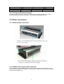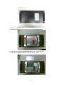
1
DVS-355
Embedded/ Mobile Digital
Video System
User Manual
-1-
Copyright and Disclaims
The documentation and the software included with this product are copyrighted 2005 by
Advantech Co., Ltd. All rights are reserved. Advantech Co., Ltd. reserves the right to make
improvements in the products described in this manual at any time without notice. No part of
this manual may be reproduced, copied, translated or transmitted in any form or by any means
without the prior written permission of Advantech Co., Ltd.
While Advantech has sought to ensure the accuracy of all information in this manual,
Advantech assumes no liability to any party for any damage caused by any error or omission
contained in this manual, its updates or supplements, whether such errors or omissions result
from negligence, accident, or any other cause. In addition, Advantech assumes no liability
with respect to the application or use of any product or system in accordance with the
descriptions or instructions contained herein; including any liability for incidental or
consequential damages arising therefrom.
ADVANTECH DISCLAIMS ALL WARRANTIES REGARDING THE INFORMATION
CONTAINED HEREIN, WHETHER EXPRESSED, IMPLIED, OR STATUTORY.
Advantech reserves the right to make changes to any products described herein without
further notice and without obligation. The contents of this manual may be revised without prior
notice.
Acknowledgements
Intel and Pentium are trademarks of Intel Corporation.
Microsoft Windows and MS-DOS are registered trademarks of Microsoft Corp.
All other product names or trademarks are properties of their respective owners.
May 2007
1st Edition
Printed in Taiwan
1
Product Warranty (2 year)
Advantech warrants to you, the original purchaser, that each of its products will be free from
defects in materials and workmanship for two year from the date of purchase.
This warranty does not apply to any products which have been repaired or altered by persons
other than repair personnel authorized by Advantech, or which have been subject to misuse,
abuse, accident or improper installation. Advantech assumes no liability under the terms of this
warranty as a consequence of such events.
Because of Advantech’s high quality-control standards and rigorous testing, most of our
customers never need to use our repair service. If an Advantech product is defective, it will be
repaired or replaced at no charge during the warranty period. For out-of-warranty repairs, you
will be billed according to the cost of replacement materials, service time and freight. Please
consult your dealer for more details.
If you think you have a defective product, follow these steps:
1. Collect all the information about the problem encountered. (For example, CPU speed,
Advantech products used, other hardware and software used, etc.) Note anything abnormal
and list any onscreen messages you get when the problem occurs.
2. Call your dealer and describe the problem. Please have your manual, product, and any
helpful information readily available.
3. If your product is diagnosed as defective, obtain an RMA (return merchandize authorization)
number from your dealer. This allows us to process your return more quickly.
4. Carefully pack the defective product, a fully-completed Repair and Replacement Order Card
and a photocopy proof of purchase date (such as your sales receipt) in a shippable container.
A product returned without proof of the purchase date is not eligible for warranty
service.
5. Write the RMA number visibly on the outside of the package and
ship it prepaid to your dealer.
2
Declaration of Conformity
CE
This product has passed the CE test for environmental specifications when shielded cables
are used for external wiring. We recommend the use of shielded cables. This kind of cable is
available from Advantech. Please contact your local supplier for ordering information.
This product has passed the CE test for environmental specifications. Test conditions for
passing included the equipment being operated within an industrial enclosure. In order to
protect the product from being damaged by ESD (Electrostatic Discharge) and EMI leakage,
we strongly recommend the use of CE-compliant industrial enclosure products.
FCC Class A
Note: This equipment has been tested and found to comply with the limits for a Class A digital
device, pursuant to part 15 of the FCC Rules. These limits are designed to provide reasonable
protection against harmful interference when the equipment is operated in a commercial
environment. This equipment generates, uses, and can radiate radio frequency energy and, if
not installed and used in accordance with the instruction manual, may cause harmful
interference to radio communications. Operation of this equipment in a residential area is likely
to cause harmful interference in which case the user will be required to correct the interference
at his own expense.
Technical Support and Assistance
Step 1. Visit the Advantech web site at www.advantech.com/support
where you can find the latest information about the product. Contact your distributor, sales
representative, or Advantech's customer service center for technical support if you need
additional assistance.
Please have the following information ready before you call:
- Product name and serial number
- Description of your peripheral attachments
- Description of your software (operating system, version, application software, etc.)
- A complete description of the problem
- The exact wording of any error messages
DVS-355 Series Model
There are 3 sub-models in DVS-355 series listed below:
Part Number
DVS-355-MU25E
HDD
Support
2.5” HDD
Tray
DVS-355-ZU25E
2.5” HDD
Tray
DVS-355-SU25E
2.5” HDD
Tray
CPU
Memory
Intel Duo
Core
U2500
Intel Duo
Core
U2500
Intel Duo
Core
U2500
N/A
L2
Cache
2MB
N/A
2MB
802.11
b/g
N/A
N/A
2MB
N/A
N/A
Table 0.1 DVS-355 Model List
3
WLAN
N/A
Video
Input
6
channels
Packing List
Before installing your board, make sure that the following materials have been received:
Part Number Description
Quantity Remark
2190000902
2066035500
2 year warranty card
Driver CD
DC Jack with 2-pin pluggable terminal
block
1
1
9680001060
Wireless Antenna
1
1700060202
Y cable of KB and PS/2 Mouse
1
1700005791
Video Cable (D-sub 15P to BNC)
1
1700001394
1
DVS-355-ZU25E
only
DVS-355-MU25E
only
If any of these items are missing or damaged, contact your distributor or sales representative
immediately.
4
Safety Instructions
1. Please read these safety instructions carefully.
2. Please keep this User Manual for later reference.
3. Please disconnect this equipment from power outlet before cleaning. Don‘t use liquid or
sprayed detergent for cleaning. Use moisture sheet or clothe for cleaning.
4. For pluggable equipment, the socket-outlet shall near the equipment and shall be easily
accessible.
5. Please keep this equipment from humidity.
6. Lay this equipment on a reliable surface when install. A drop or fall could cause injury.
7. Do not leave this equipment in an uncontrolled environment; storage temperatures above
60ºC may damage the equipment.
8. The openings on the enclosure are for air convection hence protecting the equipment from
overheating. DO NOT COVER THE OPENINGS.
9. Make sure the voltage of the power source when connecting the equipment to the power
outlet.
10. Place the power cord such a way that people cannot step on it. Do not place anything over
the power cord. The power cord must be rated for the product and for the voltage and current
marked on the product’s electrical ratings label. The voltage and current rating of the cord
should be greater than the voltage and current rating marked on the product.
11. All cautions and warnings on the equipment should be noted.
12. If the equipment is not used for long time, disconnect the equipment from mains to avoid
being damaged by transient over-voltage.
13. Never pour any liquid into ventilation openings; this could cause fire or electrical shock.
14. Never open the equipment. For safety reasons, only qualified service personnel should
open the equipment.
15. If one of the following situations arise, get the equipment checked by service personnel:
a. The Power cord or plug is damaged.
b. Liquid has penetrated the equipment.
c. The equipment has been exposed to moisture.
d. The equipment has not worked well or you can not get it work according to user‘s manual.
e. The equipment has been dropped and damaged.
f. The equipment has obvious signs of breakage
16. This device complies with Part 15 of the FCC rules. Operation is subject to the following
two conditions:
a. this device may not cause harmful interference, and
b. this device must accept any interference received, including interference that may cause
undesired operation.
CAUTION!
THIS COMPUTER IS PROVIDED WITH A BATTERY-POWERED REAL-TIME CLOCK
CIRCUIT. THERE IS A DANGER OF EXPLOSION IF BATTERY IS INCORRECTLY
REPLACED. REPLACE ONLY WITH SAME OR EQUIVLENT TYPE RECOMMENDED
BY THE MANUFACTURE. DISCARD USED BATTERIES ACCORDING TO THE
MANUFACTURER’S INSTRUCTIONS.
5
Safety Precaution - Static Electricity
Follow these simple precautions to protect yourself from harm and the products from damage.
1. To avoid electrical shock, always disconnect the power from your PC chassis before you
work on it. Don't touch any components on the CPU card or other cards while the PC is on.
2. Disconnect power before making any configuration changes. The sudden rush of power as
you connect a jumper or install a card may damage sensitive electronic components.
6
Chapter 1 Overview..................................................................................................................................9
1.1 Introduction .............................................................................................................................9
1.2 Features ...................................................................................................................................9
1.2.1 High Video Capacity and Easy Integration .....................................................................9
1.2.2 Robust Casting Construction ...........................................................................................9
1.2.3 Compact Size...................................................................................................................9
1.2.4 Scalable Performance with low power consumption.......................................................9
1.2.5 Optimized Integration......................................................................................................9
1.2.6 Wide Range of Power Source........................................................................................10
1.2.7 Options for Expansion ...................................................................................................10
1.3 Hardware Specification ............................................................................................................10
1.3.1 Processor Core Logic System........................................................................................10
1.3.2 Display...........................................................................................................................11
1.3.3 Ethernet..........................................................................................................................11
1.3.4 Other ..............................................................................................................................11
1.3.5 Storage...........................................................................................................................11
1.3.6 Mechanical ....................................................................................................................11
1.3.7 Power Supply.................................................................................................................11
1.3.8 Environment Specifications...........................................................................................12
1.3.9 Certificate Approved .....................................................................................................12
1.4 Dimensions Diagram ................................................................................................................14
Chapter 2 Hardware Functionality .........................................................................................................16
2.1 Introduction of DVS-355 External I/O Connectors ..................................................................16
2.2 DVS-355 external I/O connectors ............................................................................................16
2.2.1 Power ON/OFF Button ..................................................................................................16
2.2.2 LED Indicators ..............................................................................................................16
2.2.3 Video Input Connector ..................................................................................................17
2.2.4 DVI Connector ..............................................................................................................17
2.2.5 Power Input Connector ..................................................................................................17
2.2.6 COM1 Connector ..........................................................................................................17
2.2.7 COM2 Connector ..........................................................................................................18
2.2.8 Ethernet Connector (LAN) ............................................................................................18
2.2.9 Reset Button ..................................................................................................................18
2.2.10 PS2 Keyboard/Mouse Connector.................................................................................18
2.2.11 VGA Connector...........................................................................................................19
2.2.12 USB Connector............................................................................................................19
2.2.13 TV-out and S-Video Connector...................................................................................20
2.3 Other connectors.......................................................................................................................20
2.3.1 WLAN Antenna Connector ...........................................................................................20
2.3.2 PCMCIA and Compact Flash card slots ........................................................................20
Chapter 3 Hardware Installation and Upgrade .......................................................................................22
3.1 Jumpers and Connectors...........................................................................................................22
3.2 Setting jumpers.........................................................................................................................22
3.3 COM2 RS-485/232 Jumper setting (JP2) .................................................................................23
3.4 Installing the DDRII RAM Memory Module ...........................................................................23
3.5 Installing the 2.5" Hard Disk Drive (HDD)..............................................................................25
3.6 Inserting and Removing a Compact Flash Card .......................................................................26
3.7 Connecting Power ....................................................................................................................27
Chapter 4 Award BIOS Setup ................................................................................................................25
4.1 Introduction.............................................................................................................................25
4.2 Entering Setup .......................................................................................................................25
4.3 Standard CMOS Setup.........................................................................................................26
4.4 Advanced BIOS Features ....................................................................................................27
4.5 Advanced Chipset Features ................................................................................................29
4.6 Integrated Peripherals ..........................................................................................................32
4.7 Power Management Setup ..................................................................................................37
4.8 PnP/PCI Configurations .......................................................................................................39
4.9 Password Setting ..................................................................................................................40
4.10 Save & Exit Setup ...............................................................................................................40
4.11 Exit Without Saving.............................................................................................................40
7
CHAPTER
1
Overview
This chapter gives background information
on the DVS-355 series. It shows you the
DVS-355 overview and specifications.
Sections include:
‧ Introduction
‧ Hardware Specifications
‧ DVS-355 Series Model and Packing List
‧ Chassis Dimension
8
Chapter 1 Overview
1.1 Introduction
The DVS-355M Digital Video System combines rich video capture functions and other
industrial features into a rugged, compact metal chassis for digital video applications. The
fanless operation provides high reliability when deployed in space constrained environments.
All electronics are protected in a sealed anti-vibration anti-dust housing, making the
DVS-355M ideal for harsh environment applications. Its X86 architecture offers an open
platform for easy application development or inclusion of other applications like vehicle data
recorders or global positioning systems (GPS).
1.2 Features
1.2.1 High Video Capacity and Easy Integration
‧ DVS-355M uses 2 Conexant Fusion 878A video capture chips which are certificated and
commonly used in digital video recording market. For more information about the BT878 chip,
please visit http://www.conexant.com/products/entry.jsp?id=272
DVS-355M can support up to D1 resolution with total frame rate 60fps/NTSC or 50fps/PAL.
Each Conexant Fusion 878A can switch 3 video inputs. With this share frame technology,
DVS-355M can run up to 6 channel video inputs.
Also, DVS-355M provides users the software development kit (SDK) for Windows-based
environment with sample program and its complete C++ source codes, which will speed the
time of system integration and save your money.
* For further information about SDK, please refer to DVA-224 SDK DLL_Version
Manaul_V1.0.pdf.
1.2.2 Robust Casting Construction
‧ Fan-less operation in Aluminum sealed construction
‧ A special cushioned design that absorbs vibration to ensure maximum reliability under harsh
conditions
1.2.3 Compact Size
‧ With its compact mounting height of 65 mm , the DVS-355 can be used under space critical
installation conditions
1.2.4 Scalable Performance with low power consumption
‧ Intel Ultra Low Voltage Core Duo U2500 processor system to bring high computing
performance with low power consumption
1.2.5 Optimized Integration
‧ Few Parts, Easy Integration, Easy Maintenance to reduce investment
‧ Systems are supplied ready to run
‧ Long life cycle support for product continuity
9
1.2.6 Wide Range of Power Source
Wide range of DC 9V~30V power source offers flexibility of power input for various automation
environments.
1.2.7 Options for Expansion
DVS-355M provides Compact Flash slot, CardBus slot, COM1: RS-232, COM2:
RS-485/RS-422 and 4xUSB 2.0 ports which can fit most of application scenario. If users need
more DI, DO or COM ports, Advantech provides the following option for easy expansion:
RS-232/422/485 expansion option
Product Name
Description
EDG-4504
4-port RS-232/422/485 to Ethernet data gateway
ADAM-4570
2-port RS-232/422/485 to Ethernet data gateway
ADAM-4571
1-port RS-232/422/485 to Ethernet data gateway
ADAM-4570L
2-port RS-232 to Ethernet data gateway
ADAM-4570L
1-port RS-232 to Ethernet data gateway
ADAM-4561
1-port isolated USB to RS-232/422/485 Converter
Ethernet expansion option
Product Name
Description
ADAM-6510
4-port industrial 10 Mbps Ethernet hub
ADAM-6520
5-port industrial 10/100 Mbps Ethernet hub
ADAM-6521
5-port industrial 10/100 Mbps Ethernet switch with fiber port
UNO-2058
GX1-300 Universal Network Controller with GPS/GPRS
Communication
Digital I/O expansion option
Product Name
Description
ADAM-4501
Ethernet-enabled Communication Controller with 8 Digital I/O
ADAM-4052
Isolated Digital Input Module
ADAM-4053
16-channel Digital Input Module
ADAM-4055
16-channel Isolated Digital I/O Module with LED and Modbus
ADAM-4056S
12-channel Sink Type Isolated Digital Output Module
ADAM-4056S0
12-channel Source Type Isolated Digital Output Module
ADAM-4060
4-channel Relay Output Module
ADAM-4068
8-channel Relay Output Module with Modbus and LED
For further information of above options, please visit http://www.advantech.com
1.3 Hardware Specification
1.3.1 Processor Core Logic System
CPU Type: Intel® Ultra Low Voltage Intel® Core Duo Processor, µFC-BGA 479 Package:
Model Name
DVS-355M
DVS-355S
Part Number
DVS-355-MU25E
DVS-355-SU25E
Intel® CPU Type
Core Duo U2500
Core Duo U2500
10
Intel® Chipset
Intel® 945GM / ICH7M-DH
Intel® 945GM / ICH7M-DH
DVS-355Z
DVS-355-ZU25E
Core Duo U2500
Intel® 945GM / ICH7M-DH
BIOS: 4Mbit Flash BIOS, supports Plug & Play, APM 1.2
System Memory
- Two 200 pin SO-DIMM sockets, support ECC DDR SDRAM Up to 4GB, DDRII/533/667
DRAM
1.3.2 Display
Chipset
‧ Integrated graphics built-in Intel® 945GM GMCH, Intel Graphics Media Accelerator 950
Display Memory
‧ Shared system memory up to 224 MB
Display Interface support
‧ VGA, DVI, S-Video and TV-out Interface
1.3.3 Ethernet
‧ Ethernet Controller: Dual gigabit LAN (Marvell® 88E8053)
‧ Speed: 10/100MBps, IEEE 802.3u (100 BASE-T) protocol compatible
1.3.4 Other
‧
‧
‧
‧
Watchdog Timer: 255 levels timer interval, setup by software
Serial Port: One RS-232 port (COM1) and One RS-485/422 port (COM2)
Keyboard/Mouse: One PS/2 Port to support PS/2 Mouse and PS/2 Keyboard
USB: 4 USB 2.0 compliant universal serial bus port
1.3.5 Storage
‧ Supports a drive bay space for 2.5’’ HDD
‧ Supports a Compact Flash socket for Type I/II Compact Flash disk
1.3.6 Mechanical
‧ Construction: Aluminum housing
‧ Mounting: DIN-rail mounting, Desk/wall mounting
‧ Dimension (W x H x D):
DVS-355: 232.0 x 138.4 x 65.0 mm (9.13” x 5.45” x 2.56”); Weight: 2.3KG
1.3.7 Power Supply
‧ Maximum Output Rating 45 W
‧ Inside Fuse Rating 7 A
‧ Input Voltage: 9 ~ 30V DC,
Typical:
9 VDC @ 5.4A,
19 VDC @ 3.42 A,
11
1.3.8 Environment Specifications
‧ Operating Temperature: -10 to 50° C
Warning: Please do not keep DVS-355M working in a closed environment. The temperature
in a closed environment might get higher over the operation temperature.
‧ Relative humidity 95 % @ 40 ° C (non-condensing)
‧ Vibration loading during operation: 1Grms, IEC 68-2-64, random, 5~500Hz, 1 Oct./min,
1hr/axis.
‧ Shock during operation: 40Grms, IEC 60068-2-27, half sine, 11 ms duration
1.3.9 Certificate Approved
‧ EMC Approved: CE, FCC Class A, CCC
‧ Safety Approved: UL
12
13
1.4 Dimensions Diagram
14
CHAPTER
2
Hardware Functionality
This chapter shows how to set up the
DVS-355 hardware functions, including
connecting peripherals, switches and
indicators.
Sections include:
‧ Introduction of External I/O Connectors
‧ Front plate external I/O Connectors
‧ Power Connector
‧ Video Input Connectors
‧ Audio Connectors
‧ Rear plate external I/O Connectors
‧ COM1 Connector
‧ COM2 Connector
‧ Ethernet Connector
‧ PS2 Keyboard/Mouse Connector
‧ VGA Connector
‧ USB Connector
15
Chapter 2 Hardware Functionality
2.1 Introduction of DVS-355 External I/O Connectors
The following two figures show the external I/O connectors on DVS-355. The following
sections give you detailed information about the function of each I/O connector.
Figure 2.1: DVS-355 front metal face plate external I/O connectors
Figure 2.2: DVS-355 rear metal face plate I/O connectors
2.2 DVS-355 external I/O connectors
2.2.1 Power ON/OFF Button
The DVS-355 comes with a Power On/Off button, that Support dual function Soft Power
-On/Off (Instant off or Delay 4 Second), and Suspend.
2.2.2 LED Indicators
There are two LEDs on the DVS-355 front face plate for indicating system status: PWR LED is
for power status and flash in green color; and HDD LED is for hard disk and compact flash disk
status, which flash in red color.
16
2.2.3 Video Input Connector
The DVS-355 can support up to 6 channel video inputs with customization video cables.
DVS-355 has a high integration capture module with 2 Conexant Fusion 878A video chips.
Each 878A chip can run with 30 frames per second at NTSC or 25 fps at PAL up to D1
resolution. Also, each 878A chip can accept 3 channel video input to share the total 30/25
frames.
Note: Above information are the characteristics of Conexant Fusion 878A video chip and
DVS-355 series. The actual frame rate and performance will depend on the video input setting,
compression codec, the CPU type, the DRAM capacity/speed, the video content (Moving or
still), the brightness and etc.
2.2.4 DVI Connector
The DVS-355 can support DVI input.
1
8
9
16
17
24
2.2.5 Power Input Connector
The DVS-355 comes with a Phoenix connector that carries 9~30 VDC external power input.
Table 2.1
Pin
1
Power connector pin assignments
Definition
Ground
Pin
2
Definition
+9~30VDC
2.2.6 COM1 Connector
The DVS-355 provides a D-sub 9-pin connector, which offers one standard RS-232 serial
communication interface port of COM1.
Table 2.2
Pin
1
2
3
4
5
COM1 standard serial port pin assignments
Definition
Pin
DCD
6
RxD
7
TxD
8
DTR
9
GND
N/A
17
Definition
DSR
RTS
CTS
RI
N/A
2.2.7 COM2 Connector
The DVS-355 provides a D-sub 9-pin connector, which offers one changeable serial
communication interface port for COM2. The default setting of COM2 is RS-232.
Table 2.3
Pin
1
2
3
4
5
6
7
8
9
COM2 standard serial port pin assignments
RS-485
DATADATA+
No Connection
No Connection
GND
No Connection
No Connection
No Connection
No Connection
RS-422
TxTx+
Rx+
RxGND
No Connection
No Connection
No Connection
No Connection
2.2.8 Ethernet Connector (LAN)
The DVS-355 is equipped with Dual gigabit LAN with Marvell® 88E8053 Fast Ethernet
controller. The Ethernet port provides a standard RJ-45 jack connector with LED indicators on
the front side to show its Active/Link status (Green LED) and Speed status (white LED).
Table 2.4
Pin
1
2
3
4
5
6
7
8
RJ-45 Connector pin assignments
10/100BaseT Signal Name
XMT+
XMTRCV+
No Connection
No Connection
RCVNo Connection
No Connection
2.2.9 Reset Button
Press the "Reset" button to activate the reset function.
2.2.10 PS2 Keyboard/Mouse Connector
The DVS-355 provides a PS/2 keyboard/mouse connector. A 6-pin mini-DIN connector is
located on the rear face plate. It comes with an external Y cable to convert from the 6-pin
mini-DIN connector to PS/2 keyboard and PS/2 mouse connection.
18
Table 2.5
Pin
1
2
3
4
5
6
PS2 Keyboard/Mouse Connector
Definition
PS2_KBDAT
PS2_MSDAT
GND
VCC
PS2_KBCLK
PS2_MSCLK
2.2.11 VGA Connector
The DVS-355 provides a high resolution VGA interface by a D-sub 15-pin connector to support
a VGA CRT monitor. It supports VGA and VESA, up to 1600 x 1200 @85-Hz resolution and up
to 32 MB shared memory.
Table 2.6
Pin
1
2
3
4
5
6
7
8
VGA Connector
Definition
Red
Green
Blue
No Connection
GND
GND
GND
GND
Pin
9
10
11
12
13
14
15
N/A
Definition
No Connection
GND
No Connection
No Connection
H-SYNC
V-SYNC
No Connection
N/A
2.2.12 USB Connector
The DVS-355 provides 4 connectors for USB interface, which gives complete Plug & Play and
hot swapping for up to 127 external devices. The USB interface complies with USB UHCI, Rev.
2.0 compliant. The USB interface can be disabled in the system BIOS setup.
The USB connector is used for connecting any device that conforms to the USB interface.
Many recent digital devices conform to this standard. The USB interface supports Plug and
Play, which enables you to connect or disconnect a device whenever you want, without turning
off the computer.
19
Table 2.7
Pin
1
2
USB Connector
Definition
VCC
USB_P-
Pin
3
4
Definition
USB_P+
GND
2.2.13 TV-out and S-Video Connector
DVS-350 provides various connectors for display. It also provides composite TV-out and
S-Video except VGA and DVI connectors. It is flexible for dual display purpose.
2.3 Other connectors
2.3.1 WLAN Antenna Connector
2.3.2 PCMCIA and Compact Flash card slots
DVS-355 series provide PCMCIA and CF card slot which can hold one Type II card or one
Type I extension modules. It is flexible to connect various modules such as telecommunication
module, WLAN module, etc.
20
CHAPTER
3
Hardware Installation
and Upgrade
This chapter introduces how to initialize the
DVS-355.
Sections include:
‧ Installing the DDRII RAM Memory
Module
‧ Inserting a Compact Flash Card
‧ Installing the 2.5” Hard Disk Drive (HDD)
‧ Connecting Power
21
Chapter 3 Hardware Installation and Upgrade
3.1 Jumpers and Connectors
The DVS-355 Embedded/Mobile Video System consists of a PC-based computer that is
housed in a aluminum top cover, a metal bottom case with accessed bottom cover and front
with rear metal face plate. The HDD, RAM, are accessible by removing the accessed bottom
cover. Any maintenance or hardware upgrades can be easily completed after removing the top
cover, front and rear plates. If you are a systems integrator and need to know how to
completely disassemble the embedded box computer, you can find more useful information in
Chapter 8.
Warning!
Do not remove any mechanical parts, such as the top cover, bottom cover and front with rear
face plate until you have verified that no power is flowing within the embedded box computer.
Power must be switched off and the power cord must be unplugged. Every time you service
the embedded box computer, you should be aware of this.
3.2 Setting jumpers
You can configure your DVS-355 to match the needs of your application by setting jumpers. A
jumper is the simplest kind of electrical switch. It consists of two metal pins and a small metal
clip (often protected by a plastic cover) that slides over the pins to connect them. To “close” a
jumper, you connect the pins with the clip. To “open” a jumper you remove the clip. Sometimes
a jumper will have three pins, labeled 1, 2, and 3. In this case, you would connect either pins 1
and 2 or pins 2 and 3.
The jumper settings are schematically depicted in this manual as follows:
22
A pair of needle-nose pliers may be helpful when working with jumpers. If you have any doubts
about the best hardware configuration for your application, contact your local distributor or
sales representative before you make any changes.
3.3 COM2 RS-485/232 Jumper setting (JP2)
The COM2 port located on front metal face plate of DVS-355 unit which can be configured to
operate in RS-485 (default setting) or RS-422 mode by setting up the Jumper Pins of JP2
located on internal motherboard of DVS-355 unit.
Table 3.1: JP2: COM2 RS-485/232 selection
Setting
JP2 (1-2 closed), (9-11 closed), (10-12 closed), (15-17 closed), (16-18 closed)
JP2 (5-6 closed), (7-9 closed), (8-10 closed), (13-15 closed), (14-16 closed)
Function
RS-485
RS-232
3.4 Installing the DDRII RAM Memory Module
The DVS-355 provides one 200-pin SODIMM (Small Outline Dual Inline Memory Module)
socket and supports 2.5V DDRII RAM. You can install from 64 MB up to 1 GB of DDRII RAM
memory. The procedure of installing a DDRII RAM SODIMM into the DVS-355 is detailed
below, please follow these steps carefully.
1. Remove the power line first.
2. Unscrew the screws from the bottom cover of the DVS-355.
23
3. Remove the bottom cover.
4. Unscrew the screws from the bottom cover of SODIMM DDRII RAM
4. Plug and Push a DDRII SODIMM RAM (200pin) into a socket on board.
5. Press down the DRAM module and you will hear the “Click”.
24
6. Screw back the bottom cover of DDRII SODIMM RAM with two screws and the bottom cover
with four screws.
3.5 Installing the 2.5" Hard Disk Drive (HDD)
You can attach one enhanced Integrated Device Electronics (IDE) hard disk drive to the
DVS-355’s internal controller which uses a PCI localbus interface. The advanced IDE
controller supports faster data transfer and allows the IDE hard drive to exceed 528 MB.
For the automotive application and harsh(high temperature) environment installation, we
STRONGLY suggest users to use the wide-range 2.5” hard disk driver designed and
manufactured specifically for these application. As we know, Seagate EE25 Series hard drive
and Fujitsu MHT2020AC hard drive can meet higher operating temperature (–30º to 85ºC)
and vibration tolerance (Up to 2.0 Gs). For more information about the wide-range hard drives,
we suggest you Google the “Seagate EE25 Series” and “Fujitsu MHT2020AC” on web. You
should find some useful information from the internet.
The following are instructions for installation:
1. Remove the power line first.
2. Unscrew the screws on HDD mounting bottom cover of the DVS-355
3. Remove the HDD mounting bottom cover of the DVS-355.
4. Fixing your HDD to HDD mounting bottom cover by using the 4 screws stored in
accessories box. Make sure the PCB side down and the label side up.
25
5. Connect the IDE flat cable to the connector on the hard disk.
6. Make sure the tight connection between the flat cable and the hard disc drive.
7. Screw back the bottom cover with the four screws.
3.6 Inserting and Removing a Compact Flash Card
The procedure of installing a Compact Flash card into the DVS-355 is detailed below, please
follow these steps carefully:
1. Remove the power line first.
2. Unscrew the two screws from the CF Door located on rear face plate of the DVS-355
embedded box computer.
26
3. Remove the CF cover.
4. Match the size of the slide on both sides of CF card first before inserting the CF card.
5. Insert the Compact Flash card slightly into the CF socket.
6. DO NOT push the CF card too hard when the slide is not matching. It might cause damage
to the CF card and the socket. When it’s not easy to slide the CF card into the socket, you
need to flip the CF card over and try again.
7. Use a screw tool to push the CF card inward to make sure a tight connection between CF
card and socket.
Warning: Be careful not to touch and push any component on the PCB board.
3.7 Connecting Power
Connect the DVS-355 to a 9~30V (~60/65Watt) DC power source. The power source can
either be from a power adapter or an in-house power source.
Warning: For the automotive application, the power voltage is very unstable during the
key ignition and might be lower to 7V DC. Please make sure the system is not under
booting or operating. The unstable power source might cause the shot-down to the
system and the data loss.
27
CHAPTER
4
Award BIOS Setup
28
Chapter 4 Award BIOS Setup
4.1 Introduction
Award’s BIOS ROM has a built-in setup program that allows users to modify the basic system
configuration. This type of information is stored in battery-backed memory (CMOS RAM) so
that it retains the setup information when the power is turned off.
4.1.1 CMOS RAM Auto-backup and Restore
The CMOS RAM is powered by an onboard button cell battery. When you finish BIOS setup,
the data in CMOS RAM will be automatically backed up to Flash ROM. If operation in harsh
industrial environments causes a soft error, BIOS will recheck the data in CMOS RAM and
automatically restore the original data in Flash ROM to CMOS RAM for booting.
Note: If you intend to change the CMOS setting without restoring the previous backup, you
have to click on "DEL" within two seconds of the "CMOS checksum error..." display screen
message appearing. Then enter the "Setup" screen to modify the data. If the "CMOS
checksum error..."message appears again and again, please check to see if you need to
replace the battery in your system.
4.2 Entering Setup
Turn on the computer and check for the “patch code”. If there is a number assigned to the
patch code, it means that the BIOS support your CPU. If there is no number assigned to the
patch code, please contact Advantech’s applications engineer to obtain an up-to-date patch
code file. This will ensure that your CPU’s system status is valid. After ensuring that you have
a number assigned to the patch code, pressing <Del> to allow you to enter the setup
25
Figure 4.1: Award BIOS Setup initial screen
4.3 Standard CMOS Setup
Choose the “Standard CMOS Features” option from the “Initial Setup Screen” menu, and the
screen below will be displayed. This menu allows users to configure system components such
as date, time, hard disk drive, floppy drive, display, and memory.
Figure 4.2: Standard CMOS features screen
26
4.4 Advanced BIOS Features
The “Advanced BIOS Features” screen appears when choosing the “Advanced BIOS
Features” item from the “Initial Setup Screen” menu. It allows the user to configure the
DVS-355 according to his particular requirements. Below are some major items that are
provided in the Advanced BIOS Features screen. A quick booting function is provided for your
convenience. Simply enable the Quick Booting item to save yourself valuable time
Figure 4.3: Advanced BIOS features screen
4.4.1 CPU Feature
Press Enter to configure the settings relevant to CPU Feature.
4.4.2 Virus Warning
If enabled, a warning message and alarm beep activates if someone attempts to write here.
The commands are “Enabled” or “Disabled.”
4.4.3 CPU L1 & L2 Cache
Enabling this feature speeds up memory access. The commands are “Enabled” or “Disabled.”
27
4.4.4 Quick Power On Self Test
This option speeds up the Power-On Self Test (POST) conducted as soon as the computer is
turned on. When enabled, BIOS shortens or skips some of the items during the test. When
disabled, the computer conducts normal POST procedures.
4.4.5 First/Second/Third/ Boot Other Device
The BIOS tries to load the OS with the devices in the sequence selected. Choices are: Floppy,
LS/ZIP, HDD, SCSI, CDROM, LAN, Disabled.
4.4.6 Swap Floppy Drive
Logical name assignments of floppy drives can be swapped if there is more than one floppy
drive. The commands are “Enabled” or “Disabled.”
4.4.7 Boot UP Floppy Seek
Selection of the command “Disabled” will speed the boot up. Selection of “Enabled” searches
disk drives during boot up.
4.4.8 Boot Up NumLock Status
This feature selects the “power on” state for NumLock. The commands are “Enabled” or
“Disabled.”
4.4.9 Gate A20 Option
Normal: A pin in keyboard controller controls GateA20
Fast (Default): Chipset controls GateA20
The typematic rate is the rate key strokes repeat as determined by the keyboard controller.
The commands are “Enabled” or “Disabled.” Enabling allows the typematic rate and delay to
be selected.
4.4.10 Typematic Rate (Chars/Sec)
BIOS accepts the following input values (characters/second) for typematic rate: 6, 8, 10, 12, 15,
20, 24, 30.
4.4.11 Typematic Delay (msec)
Typematic delay is the time interval between the appearance of two consecutive characters,
when holding down a key. The input values for this category are: 250, 500, 750, 1000 (msec).
4.4.12 Security Option
28
This field allows you to limit access to the System and Setup. The default value is Setup. When
you select System, the system prompts for the User Password every time you boot up. When
you select Setup, the system always boots up and prompts for the Supervisor Password only
when the Setup utility is called up.
4.4.13 APIC Mode
APIC stands for Advanced Programmable Interrupt Controller. The default setting is Enabled.
4.4.14 MPS Version Control For OS
This option specifies the MPS (Multiprocessor Specification) version for your operating system.
MPS version 1.4 added extended configuration tables to improve support for multiple PCI bus
configurations and improve future expandability. The default setting is 1.4.
4.4.15 OS Select for DRAM > 64MB
This option allows the system to access greater than 64MB of DRAM memory when used with
OS/2 that depends on certain BIOS calls to access memory. The default setting is Non-OS/2.
4.4.16 Report No FDD For WIN 95
If you are using Windows 95/98 without a floppy disk drive, select Enabled to release IRQ6.
This is required to pass Windows 95/98's SCT test. You should also disable the Onboard FDC
Controller in the Integrated Peripherals screen when there's no floppy drive in the system. If
you set this feature to Disabled, the BIOS will not report the missing floppy drive to Win95/98.
4.4.17 Small Logo (EPA) Show
The EPA logo appears at the right side of the monitor screen when the system is boot up. The
default setting is Enabled.
4.5 Advanced Chipset Features
The “Advanced Chipset Features” screen appears when choosing the “Advanced Chipset
Features” item from the “Initial Setup Screen” menu. It allows the user to configure the system
chipset according to his particular requirements. Below are some major items that are provided
in the Advanced Chipset Features screen.
29
Figure 4.4: Advanced Chipset features screen
4.5.1 DRAM Timing Selectable
This option refers to the method by which the DRAM timing is selected. The default is By SPD.
4.5.2 CAS Latency Time
You can configure CAS latency time in HCLKs as 2 or 2.5 or 3. The system board designer
should set the values in this field, depending on the DRAM installed. Do not change the values
in this field unless you change specifications of the installed DRAM or the installed CPU.
4.5.3 Active to Precharge Delay
The default setting for the Active to Precharge Delay is 7.
4.5.4 DRAM RAS# to CAS# Delay
This option allows you to insert a delay between the RAS (Row Address Strobe) and CAS
(Column Address Strobe) signals. This delay occurs when the SDRAM is written to, read from
or refreshed. Reducing the delay improves the performance of the SDRAM.
4.5.5 DRAM RAS# Precharge
This option sets the number of cycles required for the RAS to accumulate its charge before the
SDRAM refreshes. The default setting for the Active to Precharge Delay is 3.
4.5.6 DRAM Data Integrity Mode
30
Select ECC if your memory module supports it. The memory controller will detect and correct
single-bit soft memory errors. The memory controller will also be able to detect double-bit
errors though it will not be able to correct them. This provides increased data integrity and
system stability.
4.5.7 MGM Core Frequency
This field sets the frequency of the DRAM memory installed. The default setting is Auto Max
266MHz.
4.5.8 System BIOS Cacheable
The setting of Enabled allows caching of the system BIOS ROM at F0000h-FFFFFh, resulting
in better system performance. However, if any program writes to this memory area, a system
error may result.
4.5.9 Video BIOS Cacheable
The Setting Enabled allows caching of the video BIOS ROM at C0000h-C7FFFh, resulting in
better video performance. However, if any program writes to this memory area, a system error
may result.
4.5.10 Memory Hole At 15M-16M
In order to improve performance, certain space in memory can be reserved for ISA cards. This
memory must be mapped into the memory space below 16 MB. The choices are Enabled and
Disabled.
4.5.11 Delayed Transaction
The chipset has an embedded 32-bit posted write buffer to support delay transactions cycles.
Select Enabled to support compliance with PCI specification version 2.1.
4.5.12 Delay Prior to Thermal
This field activates the CPU thermal function after the systems boots for the set number of
minutes. The options are 16Min and 64Min.
4.5.13 AGP Aperture Size (MB)
The field sets aperture size of the graphics. The aperture is a portion of the PCI memory
address range dedicated for graphics memory address space. Host cycles that hit the aperture
range are forwarded to the AGP without any translation. The default setting is 64M.
4.5.14 On-Chip VGA
31
The default setting is Enabled.
4.5.15 On-Chip Frame Buffer Size
The default setting is 32MB. The options available include 1MB, 4MB, 8MB and 16MB.
4.5.16 Boot Display
The default setting is CRT+LVDS. The options available include CRT, LVDS, DVI and TV.
4.5.17 Panel Number
These fields allow you to select the LCD Panel type. The setting values for these ports are:
640 x 480 18bit SC
800 x 600 18bit SC
1024 x 768 18bit SC
1280 x 1024 24bit SC
1400 x 1050 18bit SC
1024 x 768 24bit SC
1600 x 1200 24bit SC
4.6 Integrated Peripherals
This section sets configurations for your hard disk and other integrated peripherals. The first
screen shows three main items for user to select. Once an item selected, a submenu appears.
Details as follows.
The item of “Watch Dog Timer ” is special design for DVS-355, user could change the item to
setup 10 seconds,20sec,30sec etc. User could install the WDT sample program to enable the
Watch Dog Timer for specific application.
32
Figure 4.5: Integrated Peripherals
4.6.1 On-Chip Primary PCI IDE
Some UDMA cables use a hole in the ribbon cable as a cable detect mechanism to determine
if a UDMA IDE or standard IDE cable is installed. The default setting is “Enabled”.
4.6.2 IDE Master/Slave PIO/UDMA Mode,
IDE Primary (Secondary) Master/Slave PIO/UDMA Mode (Auto) Each channel (Primary and
Secondary) has both a master and a slave, making four IDE devices possible. Because each
IDE device may have a different Mode timing (0, 1, 2, 3, 4), it is necessary for these to be
independent. The default setting “Auto” will allow auto-detection to ensure optimal
performance.
4.6.3 On-Chip Secondary PCI IDE
If you enable IDE HDD Block Mode, the enhanced IDE driver will be enabled. Leave IDE HDD
Block Mode on the default setting.
4.6.4 IDE HDD Block Mode
You can enable the Primary IDE channel and/or the Secondary IDE channel. Any channel not
enabled is disabled. This field is for systems with only SCSI drives.
33
Figure 4.6: OnChip IDE Device
4.6.5 USB/USB 2.0 Controller
Select Enabled if your system contains a Universal Serial Bus (USB) controller and you have
USB peripherals. The choices: Enabled, Disabled.
4.6.6 USB Keyboard/Mouse Support
Select Enabled if user plan to use an USB keyboard. The choice: Enabled, Disable.
4.6.7 AC97 Audio/Modem
Select Disable if you do not want to use AC-97 audio/Modem. Option is Auto, Disable.
4.6.8 Init Display First
This item allows you to choose which one to activate first, PCI Slot or onchip VGA. The
choices: PCI Slot, Onboard/AGP.
34
Figure 4.7: Onboard Device
4.6.9 Onboard LAN Control
Option is Enable and Disable. Select Disable if user does not want to use onboard LAN
controller
4.6.10 Onboard FDC Controller
When enabled, this field allows you to connect your floppy disk drives to the onboard floppy
disk drive connector instead of a separate controller card. If you want to use a different
controller card to connect the floppy disk drives, set this field to Disabled.
4.6.11 Onboard Serial Port
For settings reference the Appendix for the serial resource allocation, and Disabled for the
on-board serial connector.
4.6.12 UART Mode Select
This item allows you to select UART mode. The choices: IrDA, ASKIR, Normal.
4.6.13 RxD, TxD Active
This item allows you to determine the active of RxD, TxD. The Choices: “Hi, Hi,” “Lo, Lo,” “Lo,
Hi,” “Hi, Lo.”
4.6.14 IR Transmission Delay
This item allows you to enable/disable IR transmission delay. The choices: Enabled, Disabled.
35
4.6.15 UR2 Duplex Mode
This item allows you to select the IR half/full duplex function. The choices: Half, Full.
4.6.16 Onboard Parallel Port
This field sets the address of the on-board parallel port connector. You can select either
3BCH/IRQ7, 378H/IRQ7, 278H/IRQ5 or Disabled. If you install an I/O card with a parallel port,
make sure there is no conflict in the address assignments. The CPU card can support up to
three parallel ports, as long as there are no conflicts for each port.
4.6.17 Parallel Port Mode
This field allows you to set the operation mode of the parallel port. The setting “Normal” allows
normal speed operation, but in one direction only. “EPP” allows bi-directional parallel port
operation at maximum speed. “ECP” allows the parallel port to operate in bi-directional mode
and at a speed faster than the maximum data transfer rate. “ECP + EPP” allows normal speed
operation in a two-way mode.
4.6.18 EPP Mode Select
This field allows you to select EPP port type 1.7 or 1.9. The choices: EPP1.7, 1.9.
4.6.19 ECP Mode Use DMA
This selection is available only if you select “ECP” or “ECP + EPP” in the Parallel Port Mode
field. In ECP Mode Use DMA, you can select DMA channel 1, DMA channel 3, or Disable.
Leave this field on the default setting.
Figure 4.8: SuperIO Device
36
4.7 Power Management Setup
The power management setup controls the CPU card’s “green” features to save power. The
following screen shows the manufacturer’s defaults:
Figure 4.6: Power management setup screen
4.7.1 ACPI function
The choice: Enabled, Disabled.
4.7.2 Power Management
This category allows you to select the type (or degree) of power saving and is directly related
to the following modes:
1. HDD Power Down
2. Suspend Mode
There are four selections for Power Management, three of which have fixed mode settings
Table 4.1 BIOS Power Management setting
37
4.7.3 Video Off In Suspend
When system is in suspend, video will turn off.
4.7.4 Modem Use IRQ
This determines the IRQ in which the MODEM can use.The choices: 3, 4, 5, 7, 9, 10, 11, NA.
4.7.5 HDD Power Down
You can choose to turn the HDD off after one of the time intervals listed, or when the system is
in “suspend” mode. If the HDD is in a power saving mode, any access to it will wake it up.
4.7.6 Soft-Off by PWR-BTTN
If you choose “Instant-Off”, then pushing the ATX soft power switch button once will switch the
system to “system off” power mode. You can choose “Delay 4 sec.” If you do, then pushing the
button for more than 4 seconds will turn off the system, whereas pushing the button
momentarily (for less than 4 seconds) will switch the system to “suspend” mode.
4.7.7 CPU THRM-Throttling
This field allows you to select the CPU THRM-Throttling rate. The choices: 12.5%, 24.0%,
37.5%, 50.0%, 62.5%, 74.0%, 87.5%.
4.7.8 PowerOn By LAN
This item allows you to wake up the system via LAN from the remote host. The choices:
Enabled, Disabled.
4.7.9 PowerOn By Modem
When Enabled an input signal on the serial Ring Indicator (RI) line (in other words, an
incoming call on the modem) awakens the system from a soft off state. The choices: Enabled,
Disabled.
4.7.10 PowerOn By Alarm
When Enabled, your can set the date and time at which the RTC (real time clock) alarm
awakens the system from Suspend mode. The choices: Enabled, Disabled.
4.7.11 Primary IDE 0 (1) and Secondary IDE 0 (1)
When Enabled, the system will resume from suspend mode if Primary IDE 0 (1) or Secondary
IDE 0 (1) is active. The choice: Enabled, Disabled.
4.7.12 FDD, COM, LPT PORT
When Enabled, the system will resume from suspend mode if FDD, COM port, or LPT port is
active. The choice: Enabled, Disabled.
38
4.7.13 PCI PIRQ [A-D]#
When Enabled, the system will resume from suspend mode if interrupt occurs. The choice:
Enabled, Disabled.
4.8 PnP/PCI Configurations
4.8.1 PnP OS Installed
Select “Yes” if you are using a plug and play capable operating system.
Select No if you need the BIOS to configure non-boot device
Figure 4.7: PnP/PCI configurations screen
4.8.2 Reset Configuration Data
Default is Disable. Select Enable to reset Extended System Configuration Data (ESCD) if you
have installed a new add-on and system configuration has caused such a conflict that OS
cannot boot.
4.8.3 Resources controlled by:
The commands here are “Auto” or “Manual.” Choosing “manual” requires you to choose
resources from each following sub-menu. “Auto” automatically configures all of the boot and
Plug and Play devices but you must be using Windows 95 or above.
39
4.8.4 PCI/VGA Palette Snoop
This is left at “Disabled.”
4.9 Password Setting
To change the password:
1. Choose the “Set Password” option from the “Initial Setup Screen” menu and press <Enter>.
The screen will display the following message:
Please Enter Your Password
Press <Enter>.
2. If the CMOS is good or if this option has been used to change the default password, the
user is asked for the password stored in the CMOS. The screen will display the following
message:
Please Confirm Your Password
Enter the current password and press <Enter>.
3. After pressing <Enter> (ROM password) or the current password (user-defined), you can
change the password stored in the CMOS. The password must be no longer than eight (8)
characters.
Remember, to enable the password setting feature, you must first select either “Setup” or
“System” from the “Advanced BIOS Features” menu.
4.10 Save & Exit Setup
If you select this and press <Enter>, the values entered in the setup utilities will be recorded in
the CMOS memory of the chipset. The microprocessor will check this every time you turn your
system on and compare this to what it finds as it checks the system. This record is required for
the system to operate.
4.11 Exit Without Saving
Selecting this option and pressing <Enter> lets you exit the setup program without recording
any new values or changing old ones.
40