1
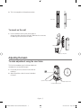
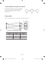
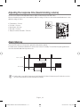
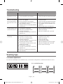
User Manual Long-Range IR Sensor SIA-0100Q/0200Q Important Safety Instructions 1. Read these instructions. 2. Keep these instructions. 3. Heed all warnings. 4. Follow all instructions. 5. Do not use this apparatus near water. 6. Clean only with dry cloth. 7. Do not block any ventilation openings, Install in accordance with the manufacturer’s instructions. 8. Do not install near any heat sources such as radiators, heat reaisters, stoves, or other apparatus (including amplifiers) that produce heat. 9. Do not defeat the safety purpose of the polarized or grounding-type plug, A polarized plug has two blades with one wider than the other. A grounding type plug has two blades and a third grounding prong. The wide blade or the third prong are provided for your safety, If the provided plug does not fit into your outlet, consult an electrician for replacement of the obsolete outlet. 10. Protect the power cord from being walked on or pinched particularly at plugs, convenience receptacles, and the point where they exit from the apparatus. 11. Only use attachments/ accessories specified by the manufacturer. 12. Use only with the cart, stand, tripod, bracket, or table specified by the manufacturer, or sold with the apparatus. When a cart is used. Use caution when moving the cart/apparatus combination to avoid injury from tip-over. 13. Unplug this apparatus during lighting storms or when unused for long periods of time. 14. Refer all servicing to qualified service personnel. Servicing is required when the apparatus has been damaged in any way, such as power-supply cord or plug is damaged, liquid has been spilled or objects have fallen into the apparatus, the apparatus has been exposed to rain or moisture, does not operate normally, or has been dropped. English _1 Z6806119901A-SIA-0100Q,0200Q.ind1 1 2010-03-30 오전 12:18:23 WARNING TO REDUCE THE RISK OF FIRE OR ELECTRIC SHOCK, DO NOT EXPOSE THIS PROCUCT TO RAIN OR MOISTURE. DO NOT INSERT ANY METALLIC OBJECT THROUGH THE VENTILATION GRILLS OR OTHER OPENNINGS ON THE EQUIPMENT. Apparatus shall not be exposed to dripping or splashing and that no objects filled with liquids, such as vases, shall be placed on the apparatus CAUTION CAUTION RISK OF ELECTRIC SHOCK. DO NOT OPEN CAUTION : TO REDUCE THE RISK OF ELECTRIC SHOCK. DO NOT REMOVE COVER (OR BACK). NO USER SERVICEABLE PARTS INSIDE. REFER SERVICING TO QUALIFIED SERVICE PERSONNEL. EXPLANATION OF GRAPHICAL SYMBOLS The lightning flash with arrowhead symbol, within an equilateral triangle, is intended to alert the user to the presence of “dangerous voltage” within the product’s enclosure that may be of sufficient magnitude to constitute a risk of electric shock to persons. The exclamation point within an equilateral triangle is intended to alert the user to the presence of important operating and maintenance (servicing) instructions in the literature accompanying the product. Class construction An apparatus with CLASS construction shall be connected to a MAINS socket outlet with a protective earthing connection. Battery Batteries(battery pack or batteries installed) shall not be exposed to excessive heat such as sunshine, fire or the like. Disconnection Device Disconnect the main plug from the apparatus, if it’s defected. And please call a repair man in your location. English _2 Z6806119901A-SIA-0100Q,0200Q.ind2 2 2010-03-30 오전 12:18:30 When used outside of the U.S., it may be used HAR code with fittings of an approved agency is employed. CAUTION These servicing instructions are for use by qualified service personnel only. To reduce the risk of electric shock do not perform any servicing other than that contained in the operating instructions unless you are qualified to do so. Please read the following recommend safety precautions carefully. y Do not Place this apparatus on an uneven surface. y Do not install on a surface where it is exposed to direct sunlight, near heating equipment or heavy cold area. y Do not place this apparatus near. y Do not attempt to service this apparatus yourself. y Do not place a glass of water on the product. y Do not install near any magnetic sources. y Do not block any ventilation openings. y Do not place heavy items on the product. User’s Manual is a guidance book how to use the products The meaning of the using sign in the book is following y Reference: in case of providing information for helping of product’s usages y Notice: If there’s any possibility to occur any damages for the goods and human caused by not following the instruction Ú Please read this manual for the safety before using of goods and keep it in the safe place. English _3 Z6806119901A-SIA-0100Q,0200Q.ind3 3 2010-03-30 오전 12:18:30 Product Features This product is a long range IR sensor, designed for the advanced 4-beam system, which can separate intrusion by an unauthorized access from just a change to the ambient circumstances • • • • • • Equipped with a high-power IR diode that is suitable for long-range detection. A 4-channel frequency system prevents confusion or conflicts between sensors when used in a multi-sensor environment. You can choose one or two transmission beams for the transmitter according to the range or to your preference. In a poor detection area, the sensor can emit an additional signal to correct the detection inadequacy. When the reception sensitivity fluctuates due to rain, fog or dew, the sensor can control the gain by making corrections. The quick installation or repair guide is provided along with a proper setting of the signal sound to enable you to set your preference. • If you want to display the alarm for an extended time for operational purposes, adjust the memory settings accordingly. • If you want to link other sensors, or use two zones as one, use the re-transmitting function. • The sensor is also featured by “Monitor Output (AGC Output)”- a display of the setting value in voltage, level indicator that displays the settings in 5 levels, adjustment of the response time, and tamper output. IR Sensor at a Glance Main Body Hood Cover Bracket Mirror Lens (Upper) View Finder Upper Lens Adjustment (Up/Down) Terminal View Finder Lens Level Fine-tuning (Upper) Blocking Film for Setting Control Panel Lower Lens Adjustment (Up/Down) Mirror Lens (Lower) Lens Level Fine-tuning (Lower) English _4 Z6806119901A-SIA-0100Q,0200Q.ind4 4 2010-03-30 오전 12:18:31 What’s Included U-shaped Bracket (x4) -shaped Bracket (x4) 4 x 25 screw (x8) 4 x 6 screw (x8) Stainless Steel Bracket (x2) Control Volume (x2) + Screw (x4) User Manual/Warranty Card Name and Function of Each Item in Control Panel Transmitter Operation LED Re-transmit LED Power 10V ~ 30V DC (nonpolar) Channel Setting (1,2) Re-transmitting (link to other sensor) Beam Power Adjustment (3) Tamper Re-transmitting Setting (4) Tamper Switch • Re-transmitting: Connect to the output point of other sensor. - If the other sensor is set to N.C mode, connect to terminals #3 and #4 (N.C). If the contact point of the linked sensor switches from N.C to N.O, the long-range IR sensor will stop emitting the infrared radiation, which plays an indirect notification role to the receiver and lights up the “Re-transmit LED”. English _5 Z6806119901A-SIA-0100Q,0200Q.ind5 5 2010-03-30 오전 12:18:32 Receiver Status Indicators (Memory/Alarm/Environment) Strength in 5 Levels Power 10V ~ 30V DC (Nonpolar) Response Time Adjustable Button Channel Setting (1,2) Alarm Out Signal Sound Setting (3) Environment Out Alarm Memory Setting (4) Tamper Level LED On/Off Tamper Switch • Alarm Out: The sensor will operate in both N.C and N.O mode • Environment Out: This output triggers if normal operation is disabled due to an environmental phenomenon such as fog. • LED Out: Turns on the indicator in 5 levels according to the setting. The signal sound will be set in 3 levels by turning on the DIP switch #3. Once adjusted, you should turn off the DIP switch. Installation To attach to the pole 1. Insert the pole support bracket to the sensor bracket. Use the screw (4x6) to tighten up the pole support bracket. You can use the pole support bracket in all sizes between Φ38 and Φ43. Pole Diameter 38mm ~ 43mm 2. Insert the U-shaped bracket and insert the sensor bracket. Insert the U-shaped bracket to the pole and use the screws (4x25) to fix the inserted sensor bracket. English _6 Z6806119901A-SIA-0100Q,0200Q.ind6 6 2010-03-30 오전 12:18:33 3. This is the completion of the bracket connection. Rear View Side View To mount on the wall 1. Use the wall-mount screws (4x16) for this purpose. Arrange the cables through the wiring hole, and mount the sensor onto the wall using the sensor screws as shown. Wiring Hole Sensor Fixing Bolt Adjusting the beam To make adjustment using the view finder This is the first mandatory step for the beam adjustment that adjusts the sensor position roughly. 1. Ensure that you can see the other sensor with the naked eye. 2. Adjust the position so that the sensor is located at the center. Up/Down Adjustable Bolt Left/Right Adjustable Dial Left/right Fine-Tuning Bolt English _7 Z6806119901A-SIA-0100Q,0200Q.ind7 7 2010-03-30 오전 12:18:34 To make adjustment using the signal sound 1. Turn on the DIP Switch #3 of the receiver. Select one of 3-sound level outputs. - Slow Separate: Beep-beep-beep - Fast Separate: Beep-beep-beep-beep-beep - Continuous: Beep~~~~~~~~~~~~ 2. After the adjustment, make sure to turn off the switch. To make adjustment using the voltmeter 1. Make adjustment as necessary using the voltmeter. Measure the output volt at DC 10V DC. 2. Insert the test probe. It is labeled in either “AGC” or “Monitor”. Voltmeter (10V DC) 3. Check the voltage status with the 5-level indicator panel. Measured Voltage Alignment 2.5V or higher Excellent 0.5V ~ 2.4V Good 0.5V or lower Poor, to be adjusted English _8 Z6806119901A-SIA-0100Q,0200Q.ind8 8 2010-03-30 오전 12:18:36 To make adjustment using the level indicator If you don’t have the voltmeter, you can use the 5-level indicator panel for fine-tuning. Note that as one indicator can displays 3 status levels (slow/fast/solid), actually the status can be separated in 15 levels. Blink Slow Blink Fast Solid IR Beam Width The beam will be eradiated at about 1.4° angle in width. See the table below for details. Distance (A) Width (B) Width (C) 100m 2.5m 2.7m 150m 3.7m 4.0m 200m 5.0m 5.2m English _9 Z6806119901A-SIA-0100Q,0200Q.ind9 9 2010-03-30 오전 12:18:37 Wiring 1) Normal 2) If two pairs are connected directly 3) If using both Alarm Out and Environment Out 4) If using the Re-transmitting function 5) Available range according to the wiring Max Distance (meter) Wire Gauge SIA-0100Q SIA-0200Q 12V DC 24V DC 12V DC AWG 22 100 900 90 24V DC 800 AWG 20 190 1,700 160 1,500 AWG 18 280 2,600 250 2,200 AWG 14 600 5,370 500 4,570 English _10 Z6806119901A-SIA-0100Q,0200Q.ind10 10 2010-03-30 오전 12:18:37 Adjusting the response time (beam blocking volume) You can use the response time adjustable volume to adjust the time between 50ms and 700ms. Where an intruder can move across an area quickly, adjust the settings to 50ms; in a fence where unauthorized access is slow, adjust the settings to 700ms. • • • • • Full-speed run – 50 msec Fast walk – 150 msec Normal walk – 250 msec Slow walk – 550 msec Jump over a fence or obstacle – 700 msec Alarm Memory Turn on the DIP switch #4 of the receiver to activate the alarm memory function. If an alarm occurs, the detector will blink for 55 minutes after 5 minutes of standby. This can inform the patrol-guard that the sensor has been activated when they arrive on site. Alarm occurrence 60 min (restart operation) Memory LED 5 min 5 min 55 min (blinking) M If another alarm occurs while the alarm memory is functioning by the first alarm, the alarm memory will consider the second one like it's the first and extend the operation time duration accordingly. English _11 Z6806119901A-SIA-0100Q,0200Q.ind11 11 2010-03-30 오전 12:18:38 Troubleshooting Problem Reason Action The power indicator of the transmitter does not turn on. 1. Power is not supplied. 2. Loose connection or short-circuited 1. Apply the power. 2. Check if the cables are properly connected. Even if I block the infrared light, the alarm indicator of the receiver does not turn on. 1. Power is not supplied. 2. Loose connection or short-circuited 3. The infrared light is incoming to the receiver after reflected by an object. 4. Two light sources are not properly blocked simultaneously. 1. Turn on the sensor. 2. Check if the cables are properly connected. 3. Remove the interruption object, or change the installation site or the orientation of the optical axis. 4. Block two light sources simultaneously. The alarm indicator of the receiver will not turn off. 1. The optical axis is dislocated. 2. There exists an obstacle between transmitter and receiver. 3. The cover of the transmitter or receiver has impurities on it. 1. Adjust the optical axis as necessary. 2. Remove the obstacle. 3. Wipe out the impurities with a soft cloth. The alarm sounds intermittently. 1. Disconnected cables 2. Fluctuation of the power voltage 3. There exists an obstacle between transmitter and receiver. 4. There exists a different strong power source around the transmitter or receiver. 5. The transmitter or receiver gets loose and unstable at its position. 6. The optical axis is dislocated. 7. The cover of the transmitter or receiver has impurities on it. 8. Sometimes a big bird or cat can block the light temporarily. 1. 2. 3. 4. 5. 6. 7. 8. Check the connection status again. Regulate the power voltage. Remove the obstacle. Change the wiring path. Secure the pole or support. Adjust the optical axis as necessary again. Wipe out the impurities with a soft cloth. Set the response time longer. Scanning Type 4-channel adjustment If you want to install multiple sensors in different ways, use the channel setting function to avoid confusion between sensors. 1) 1-Level Multi-Connection <1 CH> <2 CH> <3 CH> <4 CH> English _12 Z6806119901A-SIA-0100Q,0200Q.ind12 12 2010-03-30 오전 12:18:39 2) 2-Level Connection 3) 2-Level Multi-Connection 4) 1-level Cubic-Connection 5) 2-level Cubic-Connection Adjusting the power of the beam (DIP switch #3 of the transmitter) If you install the sensor below the minimum effective scanning range, reflection may occur. To avoid this reflection, set the range to “LOW” in less than the minimum range and set it to “HIGH” in the effective range. Model LOW HIGH SIA-0100Q 60 m 60~100 m SIA-0200Q 120 m 120~200 m English _13 Z6806119901A-SIA-0100Q,0200Q.ind13 13 2010-03-30 오전 12:18:39 Specifications Item Description Model SIA-0100Q SIA-0200Q Power Voltage DC 12V(±15%) Current Consumption Receiver: 42mA, Transmitter: 35mA (max) No. of channels 4 channels Scanning Range 100 m outside 200 m outside Response Time Output Status 50 msec ~ 700 msec Alarm Output Dry contact relay: 1 c (COM, N.C/N.O) Contact point operation time: Blocking time + 2 seconds Point of contact capacity: AC/DC 30V 1A or lower Environment Output Dry contact relay: 1 b (COM, N.C) Operation condition: Normal operation is hardly possible due to environmental condition Point of contact capacity: AC/DC 30V 1A or lower Tamper Output Dry contact relay: 1 b (COM, N.C) Operation condition: When the cover is removed due to external force Point of contact capacity: AC/DC 30V 0.1A or lower Alarm LED Lights up if an alarm occurs Memory LED Lights up if an alarm occurs under the proper memory setting Level LED 5-level indication (Excellent, Good, Fair, Realign, Poor) Beam Angle Adjustment Left/Right: ±90°, Up/Down: ±10° Features Setting by the sound Adjust the beam power (low, high) Programmed AGC Temperature -25˚C ~ 65˚C Work Environment External Material PC resin Weight 1,517g Dustproof/Waterproof Rating IP55 English _14 Z6806119901A-SIA-0100Q,0200Q.ind14 14 2010-03-30 오전 12:18:40 Appearance Sensor Unit: mm Hood English _15 Z6806119901A-SIA-0100Q,0200Q.ind15 15 2010-03-30 오전 12:18:40 Correct Disposal of This Product (Waste Electrical & Electronic Equipment) (Applicable in the European Union and other European countries with separate collection systems) This marking on the product, accessories or literature indicates that the product and its electronic accessories (e.g. charger, headset, USB cable) should not be disposed of with other household waste at the end of their working life. To prevent possible harm to the environment or human health from uncontrolled waste disposal, please separate these items from other types of waste and recycle them responsibly to promote the sustainable reuse of material resources. Household users should contact either the retailer where they purchased this product, or their local government office, for details of where and how they can take these items for environmentally safe recycling. Business users should contact their supplier and check the terms and conditions of the purchase contract. This product and its electronic accessories should not be mixed with other commercial wastes for disposal. P/No. : Z6806119901A VAN 10. 03 Z6806119901A-SIA-0100Q,0200Q.ind16 16 2010-03-30 오전 12:18:41