1
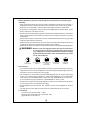
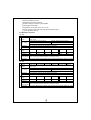
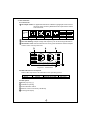
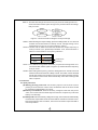
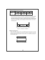
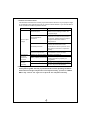
TS-200/400
Inverter Instruction Manual
TS-200/400 Inverter Instruction Manual
Index
1. Safety Guidelines ............................................................................... 1
2. Introduction ........................................................................................ 1
2.1 Features ......................................................................................... 1
2.2 Main Specification ........................................................................ 2
3. User Interface ...................................................................................... 3
3.1 Front Panel .................................................................................... 3
3.2 LED Indicator on Front Panel ......................................................
3.3 Rear Panel ....................................................................................
4. TS-200/400 setup (Output Voltage & Frequency) .............................
4.1 Initial State ..................................................................................
4.2 Procedure of Setting Up Output Voltage and Frequency............
3
3
4
4
4
5. Protection ........................................................................................... 5
5.1 Input Protection ........................................................................... 5
5.2 Output Protection ........................................................................ 6
6. Installation & Wiring .......................................................................... 6
7. Failure Correction Notes ................................................................... 9
8. Warranty ............................................................................................. 9
Jul. 2010 Version 3
1.Safety Guidelines (Please read through this manual before assembling TS200/400)
Risk of electrical shock and energy hazard. All failures should be examined by a
qualified technician. Please do not remove the case of the inverter by yourself!
Please do not install the inverter in places with high moisture or near water.
Please do not install the inverter in places with high ambient temperature, under
direct sunlight or near flame source.
Please only connect batteries with the same brand and model number in one battery
bank. Using batteries from different manufacturers or different capacity is strictly
prohibited!
Never allow a spark or flame in the vicinity of the batteries because it may generate
explosive gases during operation.
Make sure the air flow from the fan of TS-400 is not obstructed at both sides (front
and back) of the inverter. Please allow at least 15cm of space.
Please do not stack any object on the inverter because it may impede heat dissipation.
WARNING: Batteries will have aging problem after years of operation.
It is suggested to execute regular battery maintenance
(e.g. every year). Once aged, the batteries should be changed
by professional technician, or the failed batteries may cause
fire or other hazards.
Inverter
Inverter
Don't
disassemble
Keep away from
moisture
Inverter
Keep away from
fire or high
temperature
Don't stack on
the inverter
Inverter
Keep good
ventilation
2.Introduction
TS-200/400 is a DC/AC True Sine Wave Inverter using the latest high frequency
High performance inverter designed for use with battery bank drawing power from
the battery and converting it into AC voltage.
TS-200/400 can continuously provide 200W/400W of pure sine wave output with
THD < 3% to various types of loads (e.g. inductive & capacitive). It can also provide
short term power of 230W/460W for 3 minutes and 300W/600W for 10 seconds.
It can withstand surge requirement of 400W/800W for 30 AC cycles.
Reduction in product size and high efficiency of 88.5% were achieved through the
use of high frequency switching technology.
General applications include PC, ITE, vehicles, yachts, home appliances, motors,
power .
TS-200 does not have built-in fan and can be cooled with free air convection.
2.1 Features
True sine wave output (THD < 3.0%)
Rated power 200W (TS-200) / 400W (TS-400)
High efficiency up to 88.5%
1
Remote ON/OFF control
Complete protective features
Output voltage / Frequency selectable
Fully digital controlled
Compliance to UL458 / FCC / E 13 / CE
Can be used for most electronic products with AC input
3 years global warranty
2.2 Main Specification
TS-200
Model
Rated
O power
U
T AC voltage
P
U
T Waveform
Protection
Bat. voltage
range
I
N DC current
P Efficiency
U
Off mode
T
current draw
Protection
124
148
212
224
248
112
200W continuously, 230W for 3 minutes, 300W for 10 seconds, and 400W for
30 AC cycles
110Vac, 60Hz (Factory setting)
230Vac, 50Hz (Factory setting)
100/110/115/120Vac (Selectable by setting button) 200/220/230/240Vac (Selectable by setting button)
50/60Hz (Selectable by setting button)
True sine wave (THD <3.0%) at rated input voltage
AC short, overload, over temperature
10.5 ~ 15.0V 21.0 ~ 30.0V 42.0 ~ 60.0V 10.5 ~ 15.0V 21.0 ~ 30.0V 42.0 ~ 60.0V
20A
86%
10A
87.5%
5A
88%
20A
86%
10A
87.5%
5A
88%
Under 1.0mA when power switch is in the OFF position
Over current, battery reverse polarity by fuse, battery low shutdown, Battery low alarm
TS-400
Model
Rated
O power
U
T AC voltage
P
U
T Waveform
Protection
124
148
212
224
248
112
400W continuously, 460W for 3 minutes, 600W for 10 seconds, and 800W for
30 AC cycles
110Vac, 60Hz (Factory setting)
230Vac, 50Hz (Factory setting)
100/110/115/120Vac (Selectable by setting button) 200/220/230/240Vac (Selectable by setting button)
50/60Hz (Selectable by setting button)
True sine wave (THD <3.0%) at rated input voltage
AC short, overload, over temperature
Bat. voltage
10.5 ~ 15.0V 21.0 ~ 30.0V 42.0 ~ 60.0V 10.5 ~ 15.0V 21.0 ~ 30.0V 42.0 ~ 60.0V
range
I
20A
10A
40A
20A
N DC current 40A
P Efficiency
84.5%
86%
87%
86%
87.5%
U
Off mode
T
Under 1.0mA when power switch is in the OFF position
current draw
Protection
10A
88.5%
Over current, battery reverse polarity by fuse, battery low shutdown, Battery low alarm
2
3. User Interface
3.1 Front Panel
A AC output outlet: For application demands of different geographic areas all over
the world, there are many different kinds of optional AC outlets
to choose from.
Receptacle
types
Area
Type-A
Type-B
Type-C
Type-D
Type-E
Type-F
USA
Europe
Australia
U.K.
Japan
GFCI
B LED Indicating Panel: Shows inverter operating status.
C Function Setting: Output voltage and frequency can be set through this button.
D Ventilation holes: Please make sure there is good ventilation and the lifespan
of the inverter can be preserved.
D
A
B
AC OUTPUT
Status
Setting
C
Figure 3.1: Front Panel
3.2 LED indicator on front panel
Status LED: Represents TS-200/400 current operating status
Green
Orange (flashing)
Red
LED color
Status
Normal
Remote control OFF
Abnormal
*Note: Refer to section 5.2 for explanation of abnormal status
3.3 Rear panel
A Battery input (+),(-)
B Ventilation opening
C Power ON/OFF switch
D Remote control connector (JST B-XH)
E Frame ground (FG)
3
C
C
B
Reverse Polarity
Will Damage The Unit.
ON
_
_
D
_ _
OFF
Chassis
Ground
R.C
E
Reverse Polarity
Will Damage The Unit.
ON
_ _
OFF
B
Chassis
Ground
R.C
(TS-200)
A
E
D
(TS-400)
A
Figure 3.2: Rear Panel
4. TS-200/400 setup (Output Voltage & Frequency)
4.1 Initial State
The initial states of the inverters are either 110Vac/60Hz or 230Vac/50Hz. If
users need to revise it for certain application, it can be done using the setting
button on the front panel (Please refer to section 4.2). The unit will start up
automatically after the setting procedure is finished and the new settings will
be executed. These new settings will be kept even if the unit is power off/on for
any reason.
4.2 Procedure of Setting up Output Voltage and Frequency
STEP 1: The inverter should be turned off before resetting. Input batteries should
be connected and the loads should be removed.
STEP 2: Use an insulated stick to press the setting button and then turn on the
power switch. Orange led indication will flash ON and OFF. After pressing
for 5 seconds, the inverter will send out a "Beep" sound. Users can
release the button and go on with the setting procedure.
STEP 3: Please refer to Table 4-1 and check whether the output voltage is what
you need. If yes, please skip to STEP 5. If not, start from STEP 4.
AC OUTPUT
Status
Setting
Use an insulated stick to
press this setting button
Figure 4.1 Adjustment of output voltage and frequency
Table 4-1 LED indication of output voltage
Output voltage
LED
Continuous
100V/(200V)
(Red)
110V/(220V)
(Red)
Flashing
4
115V/(230V)
(Green)
120V/(240V)
(Green)
STEP 4: The LED will change state each time you press the setting button for 1
second and then release (refer to Figure 4.2). Please select the voltage
that you need.
110Vac
(220Vac)
115Vac
(230Vac)
100Vac
(200Vac)
120Vac
(240Vac)
Figure 4.2: State Circulation Diagram of Output Voltage
STEP 5: After selecting the output voltage, press the setting button for 3~5 seconds
and the inverter will send out a "Beep" sound. Voltage setting is now
finalized and you may go on to the frequency setting.
STEP 6: Please refer to Table 4-2 and check whether the output frequency is
what you need. If yes, please skip to STEP 8. If not, start from STEP 7.
Table 4-2 LED indication of frequency selection
Frequency
LED
50Hz
(Orange)
60Hz
(Orange)
Continuous
Flashing
STEP 7: The LED will change state each time you press the setting button for 1
second and then release (refer to Figure 4.2). Please select the frequency
that you need.
STEP 8: After setting the frequency, press the setting button for around 5 seconds
and the inverter will send out a "Beep" sound. The button can be released
and all the settings are finalized. The inverter will and all the settings
are finalized. The inverter will automatically store all the settings and
start to operate.
5. Protection
5.1 Input protection
(A) Battery polarity protection: If the battery input is connected in reverse
polarity, the internal fuse of the inverter would blow and the inverter should
be send back to MEAN WELL for repair.
(B) Battery low shutdown: When the battery voltage is lower then the preset
value, the inverter will automatically terminate the output thus protect the
battery from damage.
(C) Battery OVP: When the battery voltage is too high, the inverter will automatically
terminate the output and the built-in buzzer will be activated to inform the user.
After bypassing the OVP condition, the inverter should be repowered ON to
resume operation.
5
WARNING:
Please choose suitable batteries that are compatible with the rated input
DC voltage of TS-200/400 (refer to spec). If the input DC voltage is too
low (ex. using 12Vdc battery bank for 24Vdc input models), TS-200/400
will not started up. If the input DC voltage is too high (ex. using 48Vdc
battery bank for 24Vdc input models), TS-200/400 could get damaged!
5.2 Output protection
The display panel will show failure status using red LED indicators when inverter
is faced with abnormal operating conditions. This lets the user know there could
be problems with their setup.
(1) OTP: When the internal temperature is higher than the limit value, OTP will
activate and automatically shutdown the unit. Users should wait for at least
30 minutes before restarting the unit.
(2) AC output abnormal protection: When the AC output voltage of the inverter
is too low or too high, the unit will turn OFF and should be restarted again.
(3) AC output short circuit protection: When a short circuit situation occurs at
the output side of the inverter or the load increase greatly in a short period of
time, the unit will turn OFF and should be restarted again.
(4) Battery voltage abnormal protection: When the battery voltage is too high
or too low, this protection will be activated. Inverter will auto recover after
the battery voltage goes back to a safe level and the user do not need to
restart it.
(5) OLP: When the output is overloaded between 210~230W (TS-200) / 420~460W
(TS-400), the inverter can still continuously provide power for 3 minutes.
After that, if the overload condition is not removed, overload protection will
activate. When the load is higher than 400W (TS-200) / 800W (TS-400), the
overload protection will be activated instantly. For these overload protections,
once activated, the unit must reset to recover.
6. Installation & Wiring
(A)Wiring for Batteries: Wire connections should be as short as possible and less
than 1.5 meter is highly recommended. Make sure that suitable wires are chosen
based on the current rating. Too small of a cross-section will result in overheating
and could induce fire hazard.
Table 6-1 Suggestion for wire selection
Rated Current of
Equipment (Amp)
Cross-section of
Lead (mm 2)
AWG
10A ~ 13A
1.25
16
Inverter model
TS-200 TS-400
148/248
13A ~ 16A
1.5
14
124/224
16A ~ 25A
2.5
12
25A ~ 32A
4
10
32A ~ 40A
6
8
40A ~ 63A
10
6
6
148/248
112/212
124/224
112/212
(B) Suggested battery type and capacity
Battery type
Battery
capacity
Lead-acid battery
112
212
124
12V / 120Ah ~
12V / 400Ah
224
24V / 60Ah ~
24V / 200Ah
148
248
48V / 30Ah ~
48V / 100Ah
(C) Requirements for Installation
TS-400 should be mounted on a flat surface or holding rack with suitable strength.
In order to ensure the lifespan of the unit, please refrain from operating in
environment of high dust or moisture. Please make sure that ventilation is not
blocked and avoid long term operation within high ambient environment or
continuous overloading. There should be no barriers within 15cm of the
ventilating holes.
>15cm
Air
>15cm
Inverter
Air
Figure 6.1: Example of Installation
(D)Mounting Suggestion
There are 4 semi-circular cut out on the side flanges of the inverter. It can be
used for fixing TS-200/400 onto the system enclosure. We highly recommend
mounting in the horizontal position. Please make sure ventilation openings are
free from obstruction.
7
(E) Example of system diagram
As short as possible
Larger than
15cm
AC O/P
LOAD
TS-200/400
Larger than
15cm
Battery
DC I/P
-+
-
+
Chassis
Should less than 1.5m
Wall or system FG
(F) Derating
100
100
Others
80
LOAD (%)
LOAD (%)
80
60
TS-200-1xx
50
40
20
-10
60
40
20
0
10
20
30 35 40
Ambient Temperature (
50
60
10.5VDC
21VDC
42VDC
)
11.5VDC
23VDC
46VDC
15VDC (HORIZONTAL)
30VDC
60VDC
Battery Input Voltage (V)
Figure 6.2: Output Derating Curve
Figure 6.3: Input Derating Curve
(G)
Important notice on output load:
TS-200/400 Series can power most equipment that needs an AC source.
It can provide 200W (TS-200)/400W (TS-400) continuously. But for certain
types of load, the unit may not work properly.
(1) Since inductive loads or motor based equipments need a large start up current
(6~10 times the rated current), the inverter may not start up successfully with
these kind of load. The user must make sure the peak load specification of the
inverter is suitable for their application.
(2) When the output are capacitive or rectified equipment (such as switching
power supply), it is suggested to operate these equipment at no load or light
load during start up. To ensure smooth power ON, you should increase the
load only after TS-200/TS-400 has started up.
8
7. Failure Correction Notes
TS-200/400 should be serviced by a professional technician. Any improper usage
or modification may damage the unit or result in shock hazard. If you are not able to
clear the failure condition, please contact.
Status
Possible Reasons
Ways to Eliminate
Abnormal input
Check the DC input source.
Make sure the voltage is within the
required range.
Over temperature
protection
Make sure that the ventilation is not
blocked or the ambient temperature
is too high. Please derate the output
usage or reduce the ambient
temperature.
Overload protection
Make sure the output load does not
exceed the rated value or the
instantaneous start up current is not
too high (for inductive or capacitive
loads).
Short circuit protection
Make sure the output is not
overloaded or short circuited.
Discharging
period of
batteries is
too short
Batteries are aged or broken
Replace the batteries.
Fan does
not spin
(TS-400)
Clog with foreign objects
No AC output
voltage
Battery capacity is too small
Reconfirm the specification and
enlarge the battery capacity as
suggested.
Remove the foreign objects.
Repair required. Please send it back
to us or any of our distributors.
Malfunction of the fan
8. Warranty
Three years of global warranty is provided under normal operating conditions.
Please do not change components or modify the unit by yourself or MEAN
WELL may reserve the right not to provide the complete warranty.
9