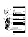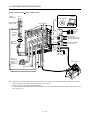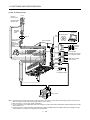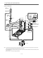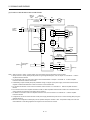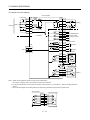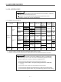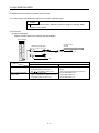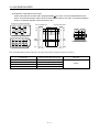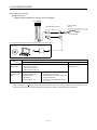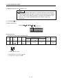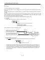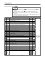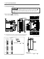
1
General-Purpose AC Servo
J3 Series
SSCNET
Fully Closed Loop Control
MODEL
J3 Series MR-J3- B-RJ006 Servo Amplifier Instruction Manual
MODEL
MODEL
CODE
This Instruction Manual uses recycled paper.
SH (NA) 030056-D (0908) MEE
Printed in Japan
Specifications subject to change without notice.
D
HEAD OFFICE : TOKYO BLDG MARUNOUCHI TOKYO 100-8310
MR-J3- B-RJ006
SERVO AMPLIFIER
INSTRUCTION MANUAL
D
Safety Instructions
(Always read these instructions before using the equipment.)
Do not attempt to install, operate, maintain or inspect the servo amplifier and servo motor until you have read
through this Instruction Manual, Installation guide, Servo motor Instruction Manual (Vol.2) and appended
documents carefully and can use the equipment correctly. Do not use the servo amplifier and servo motor until
you have a full knowledge of the equipment, safety information and instructions.
In this Instruction Manual, the safety instruction levels are classified into "WARNING" and "CAUTION".
WARNING
Indicates that incorrect handling may cause hazardous conditions,
resulting in death or severe injury.
CAUTION
Indicates that incorrect handling may cause hazardous conditions,
resulting in medium or slight injury to personnel or may cause physical
damage.
Note that the CAUTION level may lead to a serious consequence according to conditions. Please follow the
instructions of both levels because they are important to personnel safety.
What must not be done and what must be done are indicated by the following diagrammatic symbols.
: Indicates what must not be done. For example, "No Fire" is indicated by
: Indicates what must be done. For example, grounding is indicated by
.
.
In this Instruction Manual, instructions at a lower level than the above, instructions for other functions, and so
on are classified into "POINT".
After reading this installation guide, always keep it accessible to the operator.
A- 1
1. To prevent electric shock, note the following
WARNING
Before wiring or inspection, turn off the power and wait for 15 minutes or more until the charge lamp turns
off. Then, confirm that the voltage between P( ) and N( ) is safe with a voltage tester and others.
Otherwise, an electric shock may occur. In addition, always confirm from the front of the servo amplifier,
whether the charge lamp is off or not.
Connect the servo amplifier and servo motor to ground.
Any person who is involved in wiring and inspection should be fully competent to do the work.
Do not attempt to wire the servo amplifier and servo motor until they have been installed. Otherwise, you
may get an electric shock.
Operate the switches with dry hand to prevent an electric shock.
The cables should not be damaged, stressed, loaded, or pinched. Otherwise, you may get an electric
shock.
During power-on or operation, do not open the front cover of the servo amplifier. You may get an electric
shock.
Do not operate the servo amplifier with the front cover removed. High-voltage terminals and charging area
are exposed and you may get an electric shock.
Except for wiring or periodic inspection, do not remove the front cover even of the servo amplifier if the
power is off. The servo amplifier is charged and you may get an electric shock.
2. To prevent fire, note the following
CAUTION
Install the servo amplifier, servo motor and regenerative resistor on incombustible material. Installing them
directly or close to combustibles will lead to a fire.
Always connect a magnetic contactor between the main circuit power supply and L1, L2, and L3 of the
servo amplifier, and configure the wiring to be able to shut down the power supply on the side of the servo
amplifier’s power supply. If a magnetic contactor is not connected, continuous flow of a large current may
cause a fire when the servo amplifier malfunctions.
When a regenerative resistor is used, use an alarm signal to switch main power off. Otherwise, a
regenerative transistor fault or the like may overheat the regenerative resistor, causing a fire.
Provide adequate protection to prevent screws and other conductive matter, oil and other combustible
matter from entering the servo amplifier and servo motor.
Always connect a no-fuse breaker to the power supply of the servo amplifier.
A- 2
3. To prevent injury, note the follow
CAUTION
Only the voltage specified in the Instruction Manual should be applied to each terminal, Otherwise, a
burst, damage, etc. may occur.
Connect the terminals correctly to prevent a burst, damage, etc.
Ensure that polarity (
,
) is correct. Otherwise, a burst, damage, etc. may occur.
Take safety measures, e.g. provide covers, to prevent accidental contact of hands and parts (cables, etc.)
with the servo amplifier heat sink, regenerative resistor, servo motor, etc. since they may be hot while
power is on or for some time after power-off. Their temperatures may be high and you may get burnt or a
parts may damaged.
During operation, never touch the rotating parts of the servo motor. Doing so can cause injury.
4. Additional instructions
The following instructions should also be fully noted. Incorrect handling may cause a fault, injury, electric shock,
etc.
(1) Transportation and installation
CAUTION
Transport the products correctly according to their mass.
Stacking in excess of the specified number of products is not allowed.
Do not carry the servo motor by the cables, shaft or encoder.
Do not hold the front cover to transport the servo amplifier. The servo amplifier may drop.
Install the servo amplifier in a load-bearing place in accordance with the Instruction Manual.
Do not climb or stand on servo equipment. Do not put heavy objects on equipment.
The servo amplifier and servo motor must be installed in the specified direction.
Leave specified clearances between the servo amplifier and control enclosure walls or other equipment.
Do not install or operate the servo amplifier and servo motor which has been damaged or has any parts
missing.
Do not block intake and exhaust areas of the servo amplifier and servo motor which has a cooling fan.
Doing so may cause faults.
Do not drop or strike servo amplifier or servo motor. Isolate from all impact loads.
Securely attach the servo motor to the machine. If attach insecurely, the servo motor may come off during
operation.
The servo motor with a reduction gear must be installed in the specified direction to prevent oil leakage.
Take safety measures, e.g. provide covers, to prevent accidental access to the rotating parts of the servo
motor during operation.
Never hit the servo motor or shaft, especially when coupling the servo motor to the machine. The encoder
may become faulty.
Do not subject the servo motor shaft to more than the permissible load. Otherwise, the shaft may break.
When the equipment has been stored for an extended period of time, consult Mitsubishi.
A- 3
CAUTION
When you keep or use it, please fulfill the following environmental conditions.
Conditions
Environment
Ambient
temperature
In operation
In storage
Servo amplifier
Servo motor
[
]
0 to 55 (non-freezing)
0 to 40 (non-freezing)
[
]
32 to 131 (non-freezing)
32 to 104 (non-freezing)
[
]
20 to 65 (non-freezing)
[
]
4 to 149 (non-freezing)
15 to 70 (non-freezing)
5 to 158 (non-freezing)
Ambient
In operation
90
RH or less (non-condensing)
humidity
In storage
90
RH or less (non-condensing)
80
RH or less (non-condensing)
Ambience
Indoors (no direct sunlight) Free from corrosive gas, flammable gas, oil mist, dust and dirt
Altitude
Max. 1000m above sea level
HF-MP series
HF-SP51 81
HF-KP series
X, Y: 49 m/s2
HF-SP52 to 152
HF-SP524 to 1524
HC-RP Series
2
X, Y: 24.5 m/s
HC-UP72 152
HF-SP121 201
2
5.9 m/s or less at
(Note)
10 to 55Hz
Vibration
(directions of X, Y
HF-SP202 352
HF-SP2024 3524
HF-SP301 421
HC-UP202 to 502
HF-SP502 702
HF-SP5024 7024
and Z axes)
2
2
X: 24.5 m/s Y: 49 m/s
X: 24.5 m/s2 Y: 29.4 m/s2
HC-LP52 to 152
2
2
X: 9.8 m/s Y: 24.5 m/s
HC-LP202 to 302
X: 19.6 m/s2 Y: 49 m/s2
HA-LP601 to 12K1
HA-LP502 to 22K2
HA-LP701M to 15K1M
HA-LP6014 12K14
HA-LP701M4 15K1M4
2
2
X: 11.7 m/s Y: 29.4 m/s
HA-LP11K24 to 22K24
HA-LP15K1 to 25K1
HA-LP22K1M
HA-LP15K14 20K14
HA-LP22K1M4
X, Y: 9.8 m/s2
Note. Except the servo motor with a reduction gear.
When treating the servo amplifier be careful about the edged parts such as the corners of the servo
amplifier.
The servo amplifier must install in the metal cabinet (control box).
(2) Wiring
CAUTION
Wire the equipment correctly and securely. Otherwise, the servo motor may operate unexpectedly.
Do not install a power capacitor, surge absorber or radio noise filter (FR-BIF-(H) option) between the
servo motor and servo amplifier.
Connect the wires to the correct phase terminals (U, V, W) of the servo amplifier and servo motor.
Not doing so may cause unexpected operation.
A- 4
CAUTION
Connect the servo motor power terminal (U, V, W) to the servo motor power input terminal (U, V, W)
directly. Do not let a magnetic contactor, etc. intervene.
Servo amplifier
U
U
Servo motor
W
Servo motor
V
V
M
W
W
U
U
V
V
Servo amplifier
M
W
Do not connect AC power directly to the servo motor. Otherwise, a fault may occur.
The surge absorbing diode installed on the DC output signal relay of the servo amplifier must be wired in
the specified direction. Otherwise, the emergency stop and other protective circuits may not operate.
Servo amplifier
Servo amplifier
24VDC
DOCOM
Control output
signal
DICOM
24VDC
DOCOM
Control output
signal
DICOM
RA
For the sink output interface
RA
For the source output interface
When the cable is not tightened enough to the terminal block (connector), the cable or terminal block
(connector) may generate heat because of the poor contact. Be sure to tighten the cable with specified
torque.
(3) Test run adjustment
CAUTION
Before operation, check the parameter settings. Improper settings may cause some machines to perform
unexpected operation.
The parameter settings must not be changed excessively. Operation will be insatiable.
(4) Usage
CAUTION
Provide an external emergency stop circuit to ensure that operation can be stopped and power switched
off immediately.
Any person who is involved in disassembly and repair should be fully competent to do the work.
Before resetting an alarm, make sure that the run signal of the servo amplifier is off to prevent an
accident. A sudden restart is made if an alarm is reset with the run signal on.
Do not modify the equipment.
Use a noise filter, etc. to minimize the influence of electromagnetic interference, which may be caused by
electronic equipment used near the servo amplifier.
Burning or breaking a servo amplifier may cause a toxic gas. Do not burn or break a servo amplifier.
A- 5
CAUTION
Use the servo amplifier with the specified servo motor.
The electromagnetic brake on the servo motor is designed to hold the motor shaft and should not be used
for ordinary braking.
For such reasons as service life and mechanical structure (e.g. where a ball screw and the servo motor
are coupled via a timing belt), the electromagnetic brake may not hold the motor shaft. To ensure safety,
install a stopper on the machine side.
(5) Corrective actions
CAUTION
When it is assumed that a hazardous condition may take place at the occur due to a power failure or a
product fault, use a servo motor with an electromagnetic brake or an external brake mechanism for the
purpose of prevention.
Configure a circuit so that the electromagnetic brake activates with the external emergency stop at the
same time.
Contacts must be open when a trouble
(ALM) and when an electromagnetic
brake interlock (MBR).
Circuit must be
opened during
external emergency stop.
Servo motor
RA
B
24VDC
U
Electromagnetic brake
When any alarm has occurred, eliminate its cause, ensure safety, and deactivate the alarm before
restarting operation.
When power is restored after an instantaneous power failure, keep away from the machine because the
machine may be restarted suddenly (design the machine so that it is secured against hazard if restarted).
(6) Maintenance, inspection and parts replacement
CAUTION
With age, the electrolytic capacitor of the servo amplifier will deteriorate. To prevent a secondary accident
due to a fault, it is recommended to replace the electrolytic capacitor every 10 years when used in general
environment.
Please consult our sales representative.
(7) General instruction
To illustrate details, the equipment in the diagrams of this Specifications and Instruction Manual may have
been drawn without covers and safety guards. When the equipment is operated, the covers and safety
guards must be installed as specified. Operation must be performed in accordance with this
Specifications and Instruction Manual.
A- 6
About processing of waste
When you discard servo amplifier, a battery (primary battery), and other option articles, please follow the law of
each country (area).
EEP-ROM life
The number of write times to the EEP-ROM, which stores parameter settings, etc., is limited to 100,000. If
the total number of the following operations exceeds 100,000, the servo amplifier may fail when the EEPROM reaches the end of its useful life.
Write to the EEP-ROM due to parameter setting changes
Write to the EEP-ROM due to device changes
Precautions for Choosing the Products
Mitsubishi will not be held liable for damage caused by factors found not to be the cause of Mitsubishi;
machine damage or lost profits caused by faults in the Mitsubishi products; damage, secondary damage,
accident compensation caused by special factors unpredictable by Mitsubishi; damages to products other
than Mitsubishi products; and to other duties.
COMPLIANCE WITH THE EUROPEAN EC
DIRECTIVES
Refer to Appendix 5 for the compliance with EC Directives.
COMPLIANCE WITH UL/C-UL STANDARD
Refer to Appendix 6 for the compliance with UL/C-UL standard.
<<About the manuals>>
This Instruction Manual and the following Servo Amplifier/Servo Motor Instruction Manuals (Vol.2) are
required if you use the General-Purpose AC servo MR-J3- B for the first time. Always purchase them and
use the MR-J3- B safely.
A- 7
Relevant manuals
Manual name
Manual No.
MELSERVO-J3 Series MR-J3- B Servo Amplifier Instruction Manual
SH(NA)030051
MELSERVO-J3 Series Instructions and Cautions for Safe Use of AC Servos
IB(NA)0300077
MELSERVO Servo Motor Instruction Manual (Vol.2)
SH(NA)030041
EMC Installation Guidelines
IB(NA)67310
This Instruction Manual describes the functions unique to the fully closed loop control compatible servo
amplifier MR-J3- B-RJ006. Therefore, when using the MR-J3- B-RJ006, refer to the SSCNET
Compatible MR-J3- B Servo Amplifier Instruction Manual as well. However, the following items are not
described in this Instruction Manual. For details of these items, refer to the MR-J3- B Servo Amplifier
Instruction Manual.
Item
MR-J3- B Servo Amplifier Instruction Manual
INSTALLATION
CHAPTER 2
STARTUP
CHAPTER 4
GENERAL GAIN ADJUSTMENT
CHAPTER 6
SPECIAL ADJUSTMENT FUNCTIONS
CHAPTER 7
CHARACTERISTICS
CHAPTER 10
OPTIONS AND AUXILIARY EQUIPMENT
CHAPTER 11
<<About the wires used for wiring>>
Wiring wires mentioned in this instruction manual are selected based on the ambient temperature of 40
(104 ).
A- 8
CONTENTS
1. FUNCTIONS AND CONFIGURATION
1 - 1 to 1 -28
1.1 Overview................................................................................................................................................... 1 - 1
1.2 Control block diagram .............................................................................................................................. 1 - 2
1.3 Servo amplifier standard specifications................................................................................................... 1 - 3
1.4 Function list .............................................................................................................................................. 1 - 5
1.5 Selecting procedure of control mode....................................................................................................... 1 - 6
1.5.1 Control mode configuration............................................................................................................... 1 - 6
1.5.2 Dual feedback filter equivalent block diagram.................................................................................. 1 - 6
1.6 Model code definition ............................................................................................................................... 1 - 7
1.7 Combination with servo motor ................................................................................................................. 1 - 8
1.8 Structure ................................................................................................................................................... 1 - 9
1.8.1 Parts identification ............................................................................................................................. 1 - 9
1.8.2 Removal and reinstallation of the front cover.................................................................................. 1 -16
1.9 Configuration including auxiliary equipment .......................................................................................... 1 -19
1.10 System configuration ............................................................................................................................ 1 -27
2. SIGNALS AND WIRING
2 - 1 to 2 -18
2.1 Precautions for this chapter ..................................................................................................................... 2 - 2
2.2 Input power supply circuit ........................................................................................................................ 2 - 2
2.3 I/O signal connection example ............................................................................................................... 2 -14
2.4 Connector and signal arrangements ...................................................................................................... 2 -16
2.5 Internal connection diagram ................................................................................................................... 2 -17
2.6 Treatment of cable shield external conductor ........................................................................................ 2 -18
3. LOAD SIDE ENCODER
3 - 1 to 3 -20
3.1 Compatible linear encoder list ................................................................................................................. 3 - 1
3.2 Mitsubishi serial interface compatible linear encoder ............................................................................. 3 - 2
3.2.1 Linear scales manufactured by Mitutoyo Corporation (absolute type)............................................ 3 - 2
3.2.2 Linear encoder manufactured by Heidenhain Corporation.............................................................. 3 - 7
3.2.3 Linear encoder manufactured by Sony Manufacturing Systems Corporation (Incremental type) 3 -10
3.2.4 Linear encoder manufactured by Renishaw Inc. (Incremental type).............................................. 3 -12
3.3 ABZ-phase differential output load side encoder................................................................................... 3 -14
3.4 Mitsubishi optional cable connector sets.............................................................................................. 3 -17
3.4.1 MR-EKCBL M-H ............................................................................................................................ 3 -17
3.4.2 MR-ECNM ........................................................................................................................................ 3 -19
3.4.3 MR-J3CN2........................................................................................................................................ 3 -19
4. OPERATION AND FUNCTIONS
4 - 1 to 4 -22
4.1 Startup ...................................................................................................................................................... 4 - 1
4.1.1 Startup procedure.............................................................................................................................. 4 - 1
4.1.2 Selection of fully closed loop system................................................................................................ 4 - 2
4.1.3 Selection of load side encoder communication system................................................................... 4 - 3
4.1.4 Setting of load side encoder polarity ................................................................................................ 4 - 3
1
4.1.5 Setting of feedback pulse electronic gear ........................................................................................ 4 - 4
4.1.6 Confirmation of load side encoder position data.............................................................................. 4 - 6
4.1.7 Setting of fully closed loop dual feedback filter ................................................................................ 4 - 7
4.2 Home position return operation ............................................................................................................... 4 - 8
4.2.1 General precautions.......................................................................................................................... 4 - 8
4.2.2 Load side encoder types and home position return methods.......................................................... 4 - 8
4.3 Operation from controller ........................................................................................................................ 4 -12
4.3.1 Operation from controller ................................................................................................................. 4 -12
4.3.2 Servo system controller setting........................................................................................................ 4 -12
4.4 Functions ................................................................................................................................................. 4 -14
4.4.1 Fully closed loop control error detection.......................................................................................... 4 -14
4.4.2 Auto tuning function ......................................................................................................................... 4 -15
4.4.3 Machine analyzer function ............................................................................................................... 4 -15
4.4.4 Test operation mode ........................................................................................................................ 4 -16
4.5 Absolute position detection system under fully closed loop system ..................................................... 4 -16
4.6 About MR Configurator ........................................................................................................................... 4 -17
5. PARAMETERS
5 - 1 to 5 -20
5.1 Basic setting parameters (No.PA
).................................................................................................... 5 - 1
5.1.1 Parameter list .................................................................................................................................... 5 - 2
5.1.2 Parameter write inhibit ...................................................................................................................... 5 - 3
5.1.3 Selecting a control mode .................................................................................................................. 5 - 4
5.1.4 Using absolute position detection system ........................................................................................ 5 - 4
5.1.5 In-position range................................................................................................................................ 5 - 5
5.1.6 Encoder output pulse ........................................................................................................................ 5 - 5
5.2 Gain/filter parameters (No.PB
)......................................................................................................... 5 - 7
5.3 Extension setting parameters (No.PC
) ............................................................................................ 5 - 9
5.3.1 Parameter list .................................................................................................................................... 5 - 9
5.3.2 List of details..................................................................................................................................... 5 -10
5.3.3 Analog monitor ................................................................................................................................. 5 -13
5.4 I/O setting parameters (No.PD
) ...................................................................................................... 5 -16
5.4.1 Parameter list ................................................................................................................................... 5 -16
5.5 Extension control parameters (No.PE
) ........................................................................................... 5 -17
5.5.1 Parameter list ................................................................................................................................... 5 -17
5.5.2 List of details..................................................................................................................................... 5 -18
6. TROUBLESHOOTING
6 - 1 to 6 - 6
6.1 Alarms and warning list............................................................................................................................ 6 - 1
6.2 Remedies for alarms................................................................................................................................ 6 - 2
6.3 Detailed explanation of linear encoder error 1 (2A) ................................................................................ 6 - 5
7. OUTLINE DRAWINGS
7 - 1 to 7 -10
APPENDIX
App.- 1 to App.-16
App. 1 Parameter list..................................................................................................................................App.- 1
2
App. 2 Signal layout recording paper ........................................................................................................App.- 2
App. 3 Change of connector sets to the RoHS compatible products.......................................................App.- 3
App. 4 MR-J3-200B-RJ006 servo amplifiers manufactured before March 2008.....................................App.- 4
App. 5 Compliance with the european EC directives................................................................................App.- 7
App. 6 Compliance with UL/C-UL standard .............................................................................................App.-10
3
MEMO
4
1. FUNCTIONS AND CONFIGURATION
1. FUNCTIONS AND CONFIGURATION
1.1 Overview
This Instruction Manual explains the product that imports a position feedback signal from a load side encoder,
such as a linear encoder, to the MR-J3- B servo amplifier to perform fully closed loop control.
A control mode has the semi closed loop control, dual feedback control and fully closed loop control.
The control modes can be changed by the parameter setting.
For the features of each control mode, refer to section 1.2 in this manual.
[Items changed from those of the standard model (MR-J3- B)]
(a) The Mitsubishi serial interface compatible or ABZ-phase pulse train interface compatible linear encoder
is used to detect the position feedback signal of the load side encoder.
(b) In addition to the fully closed loop control that feeds back the position signal of the load side encoder, a
dual feedback control that feeds back a signal composed of the load side encoder's position feedback
signal and the motor position feedback signal has been added as an extended function.
(c) Function to switch output pulse between the load side encoder and motor side encoder
[Functions deleted from the standard model (MR-J3- B)]
(a) Speed torque control (For servo amplifiers with Software version B0 or older.)
(b) Motor-less operation (test operation)
1- 1
1. FUNCTIONS AND CONFIGURATION
1.2 Control block diagram
A fully closed loop control block diagram is shown below. The fully closed loop system is controlled in the load
side encoder unit.
Controller
Servo motor
Motor side feedback pulse
(Load side resolution unit)
(Motor side)
Droop pulses
(Motor side)
Cumulative
feedback pulses
Load side
droop pulses
Load side
cumulative
feedback pulses
S
FBN
FBD
Encoder pulse setting
(Refer to
section 5.1.6.)
Dual feedback
filter
(Note 2)
Parameter No.PE08
(Note 1, 2)
Fully closed loop selection
Parameter No.PE01, PE08
Linear encoder
Load side feedback pulse
Control
Monitoring
Fully closed loop
control error detection
function selection
Parameter No.PE03
Note. 1. Switching between semi closed loop control and fully closed loop control can be performed by changing the setting of
parameter No.PE01.
When semi closed loop control is selected, a control is always performed on the bases of the position data of the motor
encoder independently of whether the motor is at a stop or running.
2. When parameter No.PE01 "fully closed loop system" is valid, dual feedback control in which the motor feedback signal and
load side encoder feedback signal are combined by the dual feedback filter in parameter No.PE08 is performed.
In this case, fully closed loop control is performed when the motor is at a stop, and semi closed loop control is performed when
the motor is operating to improve control performance. When "4500" is set as the filter value of parameter No.PE08, fully
closed loop control is always performed.
The following table shows the functions of each control mode.
Control mode
Semi closed loop control
Dual feedback control
Fully closed loop control
Description
Feature
Position is controlled according to the motor side data.
Advantage
Since this control is insusceptible to machine influence (such as machine
resonance), the gains of the servo amplifier can be raised and the settling
time shortened.
Disadvantage
If the motor side is at a stop, the side may be vibrating or the load side
accuracy not obtained.
Feature
Position is controlled according to the motor side data and load side data.
Advantage
Control is performed according to the motor side data during operation,
and according to the load side data at a stop in sequence to raise the gains
during operation and shorten the settling time.
A stop is made with the load side accuracy.
Feature
Position is controlled according to the load side data.
Advantage
The load side accuracy is obtained not only at a stop but also during
operation.
Disadvantage
Since this control is susceptible to machine resonance or other influences,
the gains of the servo amplifier do not rise and the settling time increases.
1- 2
1. FUNCTIONS AND CONFIGURATION
1.3 Servo amplifier standard specifications
(1) 200V class, 100V class
Servo amplifier
MR-J3- -RJ006 10B
Main circuit power supply
output
Item
Rated voltage
Rated current
[A]
40B
60B
70B 100B 200B 350B 500B 700B 11KB 15KB 22KB 10B1 20B1 40B1
1.5
2.8
3.2
5.8
6.0
3-phase or 1-phase 200 to
230VAC, 50/60Hz
Voltage/frequency
Rated current
1.1
20B
[A]
Permissible voltage fluctuation
Permissible frequency
fluctuation
Power supply capacity
Inrush current
Voltage,
frequency
Rated current [A]
Permissible
voltage
Control circuit fluctuation
power supply
Permissible
frequency
fluctuation
Power
consumption [W]
Inrush current
Voltage
Interface
Power supply
power supply
capacity
Serial interface
Input
Load side
Pulse signal
encoder
train
Minimum
interface
inter- phase
face
differential
[ns]
Control System
Dynamic brake
Protective functions
Structure
(Note 3)
3.8
3.2
3-phase or 1-phase 200 to
230VAC: 170 to 253VAC
0.9
1.5
2.6
5.0
3-phase 170VAC
11.0 17.0 28.0 37.0 68.0 87.0 126.0 1.1 1.5 2.8
1-phase 100V to
3-phase 200 to 230VAC, 50/60Hz
120VAC,
50/60Hz
10.5 16.0 21.7 28.9 46.0 64.0 95.0
3.0
3-phase 170 to 253VAC
5.0
9.0
1-phase 85 to
132VAC
Within 5
Refer to section 10.2 "MR-J3- B Servo Amplifier Instruction Manual"
Refer to section 10.5 "MR-J3- B Servo Amplifier Instruction Manual"
1-phase 100 to
1-phase 200 to 230VAC, 50/60Hz
120VAC, 50/60Hz
0.2
0.3
0.4
1-phase 85 to
132VAC
1-phase 170 to 253VAC
Within 5
30
45
30
Refer to section 10.5 "MR-J3- B Servo Amplifier Instruction Manual"
24VDC 10
(Note 1) 0.15A or more
Mitsubishi high-speed serial communication
ABZ-phase differential input signal
200
Sine-wave PWM control, current control system
Built-in
External option
Built-in
Overcurrent shut-off, regenerative overvoltage shut-off, overload shut-off (electronic thermal relay),
servo motor overheat protection, encoder error protection, regenerative brake error protection,
undervoltage, instantaneous power failure protection, overspeed protection, excessive error
protection
Self-cooled,
Self-cooled, open
Force-cooling, open (IP rating: IP00)
open
(IP rating: IP00)
(IP rating: IP00)
Environmental conditions
Mounting closely (Note 2)
Ambient
temperature
Ambient
humidity
In operation
In storage
In operation
In storage
[ ]
[ ]
[ ]
[ ]
(Note 2) 0 to 55 (non-freezing)
(Note 2) 32 to 131 (non-freezing)
20 to 65 (non-freezing)
4 to 149 (non-freezing)
90 RH or less (non-condensing)
Indoors (no direct sunlight)
Free from corrosive gas, flammable gas, oil mist, dust and dirt
Altitude
Max. 1000m above sea level
Vibration
5.9m/s2 or less at 10 to 55Hz (directions of X, Y and Z axes)
[kg] 0.8 0.8 1.0 1.0 1.4 1.4 2.1 2.3 4.6 6.2
18
18
19
0.8 0.8 1.0
Mass
[lb] 1.76 1.76 2.21 2.21 3.09 3.09 4.63 5.07 10.1 13.7 39.7 39.7 41.9 1.76 1.76 2.21
Note 1. 0.15A is the value applicable when all I/O signals are used. The current capacity can be decreased by reducing the number of
I/O points.
2. When the servo amplifiers are mounting closely, operate them at the ambient temperatures of 0 to 45 (32 to 113 ) or at 75
or a smaller effective load ratio.
3. When a UL/CSA-compliant servo motor is used in combination, the value is 2.9A.
Ambient
1- 3
1. FUNCTIONS AND CONFIGURATION
(2) 400V class
Servo amplifier
MR-J3- -RJ006
60B4
100B4
200B4
350B4
1.5
2.8
5.4
8.6
500B4
700B4
11KB4
15KB4
22KB4
32.0
41.0
63.0
23.1
31.8
47.6
Main circuit power supply Output
Item
Rated voltage
3-phase 323VAC
Rated current
[A]
Voltage/frequency
Rated current
[A]
1.4
2.5
5.1
7.9
Permissible voltage fluctuation
17.0
10.8
14.4
3-phase 323 to 528VAC
Permissible frequency
fluctuation
Within 5
Power supply capacity
Refer to section 10.2 "MR-J3- B Servo Amplifier Instruction Manual"
Inrush current
Refer to section 10.5 "MR-J3- B Servo Amplifier Instruction Manual"
Voltage/frequency
1-phase 380 to 480VAC, 50/60Hz
Rated current [A]
0.1
0.2
Permissible
voltage fluctuation
Control circuit
power supply
Interface
power supply
1-phase 323 to 528VAC
Permissible
frequency
fluctuation
Within 5
Power
consumption [W]
30
Inrush current
Refer to section 10.5 "MR-J3- B Servo Amplifier Instruction Manual"
45
Voltage
24VDC 10
Power supply
capacity
(Note) 0.15A or more
Serial interface
Load side
encoder
interface
Pulse
train
interface
Mitsubishi high-speed serial communication
Input
signal
ABZ-phase differential input signal
Minimum
phase
differential
[ns]
200
Control System
Sine-wave PWM control, current control system
Dynamic brake
Built-in
Self-cooled, open
(IP rating: IP00)
Structure
Ambient
temperature
Ambient
humidity
External option
Overcurrent shut-off, regenerative overvoltage shut-off, overload shut-off (electronic thermal relay),
servo motor overheat protection, encoder error protection, regenerative brake error protection,
undervoltage, instantaneous power failure protection, overspeed protection, excessive error
protection
Protective functions
Environmental conditions
14.0
3-phase 380 to 480VAC, 50/60Hz
In operation
In storage
[
Force-cooling, open (IP rating: IP00)
]
0 to 55 (non-freezing)
[ ]
[
32 to 131 (non-freezing)
]
20 to 65 (non-freezing)
[ ]
4 to 149 (non-freezing)
In operation
90 RH or less (non-condensing)
In storage
Indoors (no direct sunlight)
Free from corrosive gas, flammable gas, oil mist, dust and dirt
Ambient
Altitude
Max. 1000m above sea level
Vibration
5.9m/s2 or less at 10 to 55Hz (directions of X, Y and Z axes)
Mass
[kg]
1.7
1.7
2.1
4.6
4.6
6.2
18
18
19
[lb]
3.75
3.75
4.63
10.1
10.1
13.7
39.7
39.7
41.9
Note. 0.15A is the value applicable when all I/O signals are used. The current capacity can be decreased by reducing the number of I/O
points.
1- 4
1. FUNCTIONS AND CONFIGURATION
1.4 Function list
The following table lists the functions of this servo. For details of the functions, refer to the reference field.
Function
High-resolution encoder
Absolute position detection
system
Gain changing function
Advanced vibration
suppression control
Adaptive filter
Low-pass filter
Machine analyzer function
Machine simulation
Gain search function
Robust disturbance
compensation
Advanced Gain search
Slight vibration suppression
control
Auto tuning
Brake unit
Power regenerative converter
Regenerative option
Alarm history clear
Output signal selection
(Device settings)
Output signal (DO)
forced output
Test operation mode
Analog monitor output
MR Configurator
Description
High-resolution encoder of 262144 pulses/rev is used as a servo motor
encoder.
Merely setting a home position once makes home position return
unnecessary at every power-on.
You can switch between gains during rotation and gains during stop or use
an external signal to change gains during operation.
This function suppresses vibration at the arm end or residual vibration.
Servo amplifier detects mechanical resonance and sets filter characteristics
automatically to suppress mechanical vibration.
Suppresses high-frequency resonance which occurs as servo system
response is increased.
Analyzes the frequency characteristic of the mechanical system by simply
connecting a MR Configurator-installed personal computer and servo
amplifier.
MR Configurator is necessary for this function.
Can simulate machine motions on a personal computer screen on the basis
of the machine analyzer results.
MR Configurator is necessary for this function.
Personal computer changes gains automatically and searches for overshootfree gains in a short time.
MR Configurator is necessary for this function.
This function provides better disturbance response in case of low response
level due to high load inertia moment ratio for the roll send axes.
MR Configurator is necessary for this function.
Advanced Gain search automatically searches for the optimum parameter for
settle time to be short.
The gain can be adjusted by setting sequentially in accordance with wizard
screens.
MR Configurator is necessary for this function.
Reference
Refer to the MR-J3B Servo Amplifier
Instruction Manual.
Suppresses vibration of 1 pulse produced at a servo motor stop.
Automatically adjusts the gain to optimum value if load applied to the servo
motor shaft varies. Higher in performance than MR-J2-Super series servo
amplifier.
Used when the regenerative option cannot provide enough regenerative
power.
Can be used the 5kW or more servo amplifier.
Used when the regenerative option cannot provide enough regenerative
power.
Can be used the 5kW or more servo amplifier.
Used when the built-in regenerative resistor of the servo amplifier does not
have sufficient regenerative capability for the regenerative power generated.
Alarm history is cleared.
The pins that output the output devices, including the trouble (ALM) and the
dynamic brake interlock (MBR), can be changed to certain pins of the CN3
connectors.
Output signal can be forced on/off independently of the servo status.
Use this function for output signal wiring check, etc.
JOG operation positioning operation DO forced output program operation.
However, MR Configurator is necessary for positioning operation.
Servo status is output in terms of voltage in real time.
Using a personal computer, parameter setting, test operation, status display,
etc. can be performed.
1- 5
Refer to the MR-J3B Servo Amplifier
Instruction Manual.
1. FUNCTIONS AND CONFIGURATION
1.5 Selecting procedure of control mode
1.5.1 Control mode configuration
In this servo, a semi closed loop system or fully closed loop system can be selected as a control system.
Also, on the fully closed loop system, the semi closed loop control, fully closed loop control and dual feedback
control can be switched by the parameter No.PE08 settings.
Semi closed loop system
Semi closed loop
control
Control mode selection
Parameter No.PA01
Controller command
Semi closed loop control/
fully closed loop control switching bit
0
MR-J3- B-RJ006
OFF
1
(Refer to section 5.1.3.)
ON
Fully closed loop
Selection 1
Parameter No.PE01
Fully closed loop system
Fully closed loop dual
feedback filter
Parameter No.PE08
1
0
0
(Refer to section 5.5.2.)
1 to 4499
4500
Semi closed loop
control
Dual feedback
control
Fully closed loop
control
1.5.2 Dual feedback filter equivalent block diagram
A dual feedback filter equivalent block diagram on the dual feedback control is shown below.
Servo motor
Positioning
controller
High-pass
filter
Linear encoder
Low-pass
filter
(Note)
Fully closed
loop control
<Dual feedback filter>
Operating status
Controlling status
At motor stop (0 to ) Fully closed loop control
At operating (from ) Semi closed loop control
Semi closed
loop control
Frequency [rad/s]
Note.
(a dual feedback filter band) is set by parameter No.PE08.
1- 6
1. FUNCTIONS AND CONFIGURATION
1.6 Model code definition
(1) Rating plate
AC SERVO
Model
Capacity
MR-J3-10B-RJ006
POWER : 100W
INPUT : 0.9A 3PH+1PH200-230V 50Hz
3PH+1PH200-230V 60Hz
1.3A 1PH 200-230V 50/60Hz
OUTPUT: 170V 0-360Hz 1.1A
SERIAL : A34230001
Applicable power supply
Rated output current
Serial number
(2) Model
MR
J3
Series
B
Fully closed loop control symbol
Standard regeneration
brake resistor
Symbol
0.1kW to 7kW 11kW to 2kW
RJ006 Built-in
Standard
(No built-in for attachment
0.1kW)
RZ006
No attachment
Power supply
Power supply
Symbol
None 3-phase or 1-phase 200
(Note 1) to 230VAC
(Note 2)
1-phase 100 to 120VAC
1
(Note 3)
3-phase 380 to 480VAC
4
Note 1. 1-phase 200V to 230V is
supported by 750W or less.
2. 1-phase 100V to 120V is
supported by 400W or less.
3. 3-phase 380VAC to 480VAC
is supported by 600W and
1kW or more.
SSCNET
compatible
Rated output
Symbol
10
20
40
60
70
100
200
Rated
Symbol Rated
output [kW]
output [kW]
350
0.1
3.5
0.2
5
500
700
0.4
7
11
0.6
11k
0.75
15
15k
22k
1
22
2
1- 7
1. FUNCTIONS AND CONFIGURATION
1.7 Combination with servo motor
The following table lists combinations of servo amplifiers and servo motors. The same combinations apply to
the models with an electromagnetic brake and the models with a reduction gear.
Servo motors
Servo amplifier
MR-J3-10B (1) -RJ006
HF-KP
HF-MP
053
053
13
HF-SP
1000r/min
2000r/min
51
52
23
23
MR-J3-40B (1) -RJ006
43
43
73
73
MR-J3-60B-RJ006
81
MR-J3-200B-RJ006
121
201
202
301
352
MR-J3-500B-RJ006
421
502
MR-J3-700B-RJ006
702
Servo motors
HA-LP
1000r/min
1500r/min
2000r/min
601
701M
702
MR-J3-500B-RJ006
MR-J3-11KB-RJ006
MR-J3-15KB-RJ006
502
MR-J3-22KB-RJ006
801
12K1
15K1
20K1
25K1
11K1M
11K2
15K1M
15K2
22K1M
22K2
Servo motors
Servo amplifier
MR-J3-60B4-RJ006
MR-J3-100B4-RJ006
MR-J3-200B4-RJ006
MR-J3-350B4-RJ006
HF-SP
1500r/min
2000r/min
524
1024
1524
2024
3524
MR-J3-500B4-RJ006
5024
MR-J3-700B4-RJ006
7024
MR-J3-11KB4-RJ006
HA-LP
1000r/min
6014
8014
12K14
52
102
152
MR-J3-350B-RJ006
MR-J3-700B-RJ006
HC-LP
72
MR-J3-100B-RJ006
Servo amplifier
HC-UP
13
MR-J3-20B (1) -RJ006
MR-J3-70B-RJ006
HC-RP
701M4
11K1M4
11K24
MR-J3-15KB4-RJ006
15K14
15K1M4
15K24
MR-J3-22KB4-RJ006
20K14
22K1M4
22K24
1- 8
102
103
153
203
353
503
152
202
352
502
152
202
302
1. FUNCTIONS AND CONFIGURATION
1.8 Structure
1.8.1 Parts identification
(1) MR-J3-100B-RJ006 or less
Name/Application
Detailed
explanation
Display
The 3-digit, seven-segment LED shows the servo
status and alarm number.
F01
3456
2
B C DE
2
F01
A
SW1
TEST
SW2
789
ON 4E
1
B CDE
3456
A
Rotary axis setting switch (SW1)
SW1
Used to set the axis No. of servo amplifier.
789
Test operation select switch (SW2-1)
Used to perform the test operation
mode by using MR Configurator.
SW2
2
1
2
Spare (Be sure to set to the "Down"
position).
Main circuit power supply connector (CNP1)
Connect the input power supply.
USB communication connector (CN5)
Connect the personal computer.
Fixed part
(2 places)
Refer to the
MR-J3- B
Servo
Amplifier
Instruction
Manual.
Section 2.2
Refer to the
MR-J3- B
Servo
Amplifier
Instruction
Manual.
I/O signal connector (CN3)
Used to connect digital I/O signals.
More over an analog monitor is output.
Section 2.3
Section 2.4
Control circuit connector (CNP2)
Connect the control circuit power supply/regenerative
option.
Section 2.2
SSCNET cable connector (CN1A)
Used to connect the servo system controller or the front
axis servo amplifier.
Refer to the
MR-J3- B
Servo
Amplifier
SSCNET cable connector (CN1B)
Used to connect the rear axis servo amplifier. For the final Instruction
Manual.
axis, puts a cap.
Servo motor power connector (CNP3)
Connect the servo motor.
Encoder connector (CN2)
Used to connect the servo motor encoder.
Load side encoder connector (CN2L)
Connect the load side encoder.
Section 2.2
Refer to the
MR-J3- B
Servo
Amplifier
Instruction
Manual.
Chapter 3
Connector for manufacturer setting
Not used for this servo amplifier.
Charge lamp
Lit to indicate that the main circuit is charged. While this
lamp is lit, do not reconnect the cables.
Battery holder
Not used for this servo amplifier.
Protective earth (PE) terminal (
Ground terminal.
Rating plate
1- 9
)
Section 2.2
Section 1.6
1. FUNCTIONS AND CONFIGURATION
(2) MR-J3-60B4-RJ006 MR-J3-100B4-RJ006
Name/Application
Detailed
explanation
Display
The 3-digit, seven-segment LED shows the servo
status and alarm number.
0
F 1
3456
2
B CDE
2
F01
A
SW1
TEST
SW2
789
ON 4E
1
B CDE
34 56
A
Rotary axis setting switch (SW1)
SW1
Used to set the axis No. of servo amplifier.
789
Test operation select switch (SW2-1)
Used to perform the test operation
mode by using MR Configurator.
SW2
2
1
2
Refer to the
MR-J3- B
Servo
Amplifier
Instruction
Manual.
Spare (Be sure to set to the "Down"
position).
Main circuit power supply connector (CNP1)
Connect the input power supply.
USB communication connector (CN5)
Connect the personal computer.
Section 2.2
Refer to the
MR-J3- B
Servo
Amplifier
Instruction
Manual.
I/O signal connector (CN3)
Used to connect digital I/O signals.
More over an analog monitor is output.
Section 2.3
Section 2.4
Control circuit connector (CNP2)
Connect the control circuit power supply/regenerative
option.
Section 2.2
SSCNET cable connector (CN1A)
Used to connect the servo system controller or the front
axis servo amplifier.
Refer to the
MR-J3- B
Servo
Amplifier
SSCNET cable connector (CN1B)
Used to connect the rear axis servo amplifier. For the final Instruction
Manual.
axis, puts a cap.
Servo motor power connector (CNP3)
Connect the servo motor.
Encoder connector (CN2)
Used to connect the servo motor encoder.
Load side encoder connector (CN2L)
Connect the load side encoder.
Fixed part
(3 places)
Section 2.2
Refer to the
MR-J3- B
Servo
Amplifier
Instruction
Manual.
Chapter 3
Battery connector (CN4)
Used to connect the battery for absolute position data
backup.
Charge lamp
Lit to indicate that the main circuit is charged. While this
lamp is lit, do not reconnect the cables.
Battery holder
Contains the battery for absolute position data backup.
Protective earth (PE) terminal (
Ground terminal.
Rating plate
1 - 10
)
Section 2.2
Section 1.6
1. FUNCTIONS AND CONFIGURATION
(3) MR-J3-200B(4)-RJ006
Name/Application
Detailed
explanation
Display
The 3-digit, seven-segment LED shows the servo
status and alarm number.
0
F 1
3456
2
34 56
F01
2
B CD E
BCDE
789
A
SW1
TEST
SW2
A
Rotary axis setting switch (SW1)
SW1
Used to set the axis No. of servo amplifier.
789
Test operation select switch (SW2-1)
Used to perform the test operation
mode by using MR Configurator.
ON 4E
1
SW2
2
1
2
Spare (Be sure to set to the "Down"
position).
Main circuit power supply connector (CNP1)
Connect the input power supply.
USB communication connector (CN5)
Connect the personal computer.
(Note)
Refer to the
MR-J3- B
Servo
Amplifier
Instruction
Manual.
Section 2.2
Refer to the
MR-J3- B
Servo
Amplifier
Instruction
Manual.
I/O signal connector (CN3)
Used to connect digital I/O signals.
More over an analog monitor is output.
Section 2.3
Section 2.4
Control circuit connector (CNP2)
Connect the control circuit power supply/regenerative
option.
Section 2.2
SSCNET cable connector (CN1A)
Used to connect the servo system controller or the front
axis servo amplifier.
Refer to the
MR-J3- B
Servo
SSCNET cable connector (CN1B)
Amplifier
Used to connect the rear axis servo amplifier. For the final
Instruction
axis, puts a cap.
Manual.
Encoder connector (CN2)
Used to connect the servo motor encoder.
Load side encoder connector (CN2L)
Connect the load side encoder.
Chapter 3
Battery connector (CN4)
Used to connect the battery for absolute position data
backup.
Servo motor power connector (CNP3)
Connect the servo motor.
Section 2.2
Battery holder
Contains the battery for absolute position data backup.
Cooling Fan
Fixed part
(3 places)
Charge lamp
Lit to indicate that the main circuit is charged. While this
lamp is lit, do not reconnect the cables.
Protective earth (PE) terminal (
Ground terminal.
Rating plate
)
Section 2.2
Section 1.6
Note. Connectors (CNP1, CNP2, and CNP3) and appearance of MR-J3-200B-RJ006 servo amplifier have been changed from April
2008 production. For existing servo amplifier, refer to appendix 4.
1 - 11
1. FUNCTIONS AND CONFIGURATION
(4) MR-J3-350B-RJ006
Name/Application
Detailed
explanation
Display
The 3-digit, seven-segment LED shows the servo
status and alarm number.
0
F 1
3456
2
B CDE
2
F01
A
SW1
TEST
SW2
789
ON 4E
1
BCDE
3456
A
Rotary axis setting switch (SW1)
SW1
Used to set the axis No. of servo amplifier.
789
Test operation select switch (SW2-1)
Used to perform the test operation
mode by using MR Configurator.
SW2
2
1
2
Refer to the
MR-J3- B
Servo
Amplifier
Instruction
Manual.
Spare (Be sure to set to the "Down"
position).
Main circuit power supply connector (CNP1)
Connect the input power supply.
USB communication connector (CN5)
Connect the personal computer.
Section 2.2
Refer to the
MR-J3- B
Servo
Amplifier
Instruction
Manual.
I/O signal connector (CN3)
Used to connect digital I/O signals.
More over an analog monitor is output.
Section 2.3
Section 2.4
Servo motor power connector (CNP3)
Connect the servo motor.
Section 2.2
SSCNET cable connector (CN1A)
Used to connect the servo system controller or the front
axis servo amplifier.
Refer to the
MR-J3- B
Servo
SSCNET cable connector (CN1B)
Amplifier
Used to connect the rear axis servo amplifier. For the final
Instruction
axis, puts a cap.
Manual.
Encoder connector (CN2)
Used to connect the servo motor encoder.
Load side encoder connector (CN2L)
Connect the load side encoder.
Chapter 3
Connector for manufacturer setting (CN4)
Not used for this servo amplifier.
Control circuit connector (CNP2)
Connect the control circuit power supply/regenerative
option.
Section 2.2
Battery holder
Not used for this servo amplifier.
Charge lamp
Lit to indicate that the main circuit is charged. While this
lamp is lit, do not reconnect the cables.
Cooling fan
Protective earth (PE) terminal (
Ground terminal.
Rating plate
Fixed part
(3 places)
1 - 12
)
Section 2.2
Section 1.6
1. FUNCTIONS AND CONFIGURATION
(5) MR-J3-350B4-RJ006 MR-J3-500B(4)-RJ006
POINT
The servo amplifier is shown without the front cover. For removal of the front
cover, refer to section 1.8.2 of the MR-J3- B Servo Amplifier Instruction
Manual.
Name/Application
Detailed
explanation
Display
The 3-digit, seven-segment LED shows the servo
status and alarm number.
0
F 1
3456
2
B CDE
2
F01
A
SW1
TEST
SW2
789
ON 4E
1
BCDE
3456
A
Rotary axis setting switch (SW1)
SW1
Used to set the axis No. of servo amplifier.
789
Test operation select switch (SW2-1)
Used to perform the test operation
mode by using MR Configurator.
SW2
2
1
2
Refer to the
MR-J3- B
Servo
Amplifier
Instruction
Manual.
Spare (Be sure to set to the "Down"
position).
USB communication connector (CN5)
Connect the personal computer.
Cooling fan
I/O signal connector (CN3)
Used to connect digital I/O signals.
More over an analog monitor is output.
Section 2.3
Section 2.4
Battery holder
Not used for this servo amplifier.
SSCNET cable connector (CN1A)
Used to connect the servo system controller or the front
axis servo amplifier.
Refer to the
MR-J3- B
Servo
SSCNET cable connector (CN1B)
Amplifier
Used to connect the rear axis servo amplifier. For the final
Instruction
axis, puts a cap.
Manual.
Encoder connector (CN2)
Used to connect the servo motor encoder.
Load side encoder connector (CN2L)
Connect the load side encoder.
Chapter 3
Connector for manufacturer setting (CN4)
Not used for this servo amplifier.
Power factor improving DC reactor terminal block (TE3)
Used to connect the power factor improving DC reactor.
Refer to the
MR-J3- B
Servo
Amplifier
Instruction
Manual.
Charge lamp
Lit to indicate that the main circuit is charged. While this
lamp is lit, do not reconnect the cables.
Main circuit terminal block (TE1)
Used to connect the input power supply and servo motor.
Fixed part
(4 places)
Control circuit terminal block (TE2)
Used to connect the control circuit power supply.
Protective earth (PE) terminal (
Ground terminal.
Rating plate
1 - 13
Section 2.2
)
Section 1.6
1. FUNCTIONS AND CONFIGURATION
(6) MR-J3-700B(4)-RJ006
POINT
The servo amplifier is shown without the front cover. For removal of the front
cover, refer to section 1.8.2 of the MR-J3- B Servo Amplifier Instruction
Manual.
Name/Application
Detailed
explanation
Display
The 3-digit, seven-segment LED shows the servo
status and alarm number.
0
F 1
3456
2
3 456
F01
2
B CD E
BCDE
A
SW1
TEST
SW2
789
A
Rotary axis setting switch (SW1)
SW1
Used to set the axis No. of servo amplifier.
789
ON 4E
1
1
Cooling fan
Test operation select switch (SW2-1)
Used to perform the test operation
mode by using MR Configurator.
SW2
2
Fixed part
(4 places)
2
Refer to the
MR-J3- B
Servo
Amplifier
Instruction
Manual.
Spare (Be sure to set to the "Down"
position).
USB communication connector (CN5)
Connect the personal computer.
I/O signal connector (CN3)
Used to connect digital I/O signals.
More over an analog monitor is output.
Section 2.3
Section 2.4
Battery holder
Contains the battery for absolute position data backup.
SSCNET cable connector (CN1A)
Used to connect the servo system controller or the front
axis servo amplifier.
Refer to the
MR-J3- B
Servo
SSCNET cable connector (CN1B)
Amplifier
Used to connect the rear axis servo amplifier. For the final
Instruction
axis, puts a cap.
Manual.
Encoder connector (CN2)
Used to connect the servo motor encoder.
Load side encoder connector (CN2L)
Connect the load side encoder.
Chapter 3
Connector for manufacturer setting (CN4)
Not used for this servo amplifier.
Power factor improving DC reactor terminal block (TE3)
Used to connect the power factor improving DC reactor.
Refer to the
MR-J3- B
Servo
Amplifier
Instruction
Manual.
Control circuit terminal block (TE2)
Used to connect the control circuit power supply.
Main circuit terminal block (TE1)
Used to connect the input power supply and servo
motor.
Protective earth (PE) terminal (
Ground terminal.
Section 2.2
)
Charge lamp
Lit to indicate that the main circuit is charged. While this
lamp is lit, do not reconnect the cables.
Rating plate
1 - 14
Section 1.6
1. FUNCTIONS AND CONFIGURATION
(7) MR-J3-11KB (4)-RJ006 to MR-J3-22KB(4)-RJ006
POINT
The servo amplifier is shown without the front cover. For removal of the front
cover, refer to section 1.8.2 of the MR-J3- B Servo Amplifier Instruction
Manual.
Name/Application
Detailed
explanation
Display
The 3-digit, seven-segment LED shows the servo
status and alarm number.
0
F 1
34 56
2
2
F01
B CDE
Cooling fan
Fixed part
(4 places)
A
SW1
TEST
SW2
789
ON 4E
1
B CD E
3456
A
Rotary axis setting switch (SW1)
SW1
Used to set the axis No. of servo amplifier.
789
Test operation select switch (SW2-1)
Used to perform the test operation
mode by using MR Configurator.
SW2
2
1
2
Refer to the
MR-J3- B
Servo
Amplifier
Instruction
Manual.
Spare (Be sure to set to the "Down"
position).
USB communication connector (CN5)
Connect the personal computer.
I/O signal connector (CN3)
Used to connect digital I/O signals.
More over an analog monitor is output.
Section 2.3
Section 2.4
Battery holder
Contains the battery for absolute position data backup.
SSCNET cable connector (CN1A)
Used to connect the servo system controller or the front
axis servo amplifier.
Refer to the
MR-J3- B
Servo
SSCNET cable connector (CN1B)
Amplifier
Used to connect the rear axis servo amplifier. For the final
Instruction
axis, puts a cap.
Manual.
Encoder connector (CN2)
Used to connect the servo motor encoder.
Load side encoder connector (CN2L)
Connect the load side encoder.
Chapter 3
Connector for manufacturer setting (CN4)
Not used for this servo amplifier.
Charge lamp
Lit to indicate that the main circuit is charged. While this
lamp is lit, do not reconnect the cables.
Rating plate
Section 1.6
Main circuit, Control circuit and Protective earth (PE)
terminal block (TE)
Used to connect the input power supply, servo motor,
regenerative option, and grounding.
Section 2.2
1 - 15
1. FUNCTIONS AND CONFIGURATION
1.8.2 Removal and reinstallation of the front cover
WARNING
Before removing or installing the front cover, turn off the power and wait for 15
minutes or more until the charge lamp turns off. Then, confirm that the voltage
between P( ) and N( ) is safe with a voltage tester and others. Otherwise, an
electric shock may occur. In addition, always confirm from the front of the servo
amplifier whether the charge lamp is off or not.
(1) For MR-J3-350B4-RJ006 MR-J3-500B(4)-RJ006 MR-J3-700B(4)-RJ006
Removal of the front cover
A)
A)
1) Hold the ends of lower side of the front cover with
both hands.
2) Pull up the cover, supporting at point A).
3) Pull out the front cover to remove.
1 - 16
1. FUNCTIONS AND CONFIGURATION
Reinstallation of the front cover
Front cover
setting tab
A)
A)
1) Insert the setting tabs on the front cover into the
sockets of the servo amplifier (2 places).
2) Pull up the cover, supporting at point A).
Setting tab
3) Push the setting tabs until they click.
1 - 17
1. FUNCTIONS AND CONFIGURATION
(2) For MR-J3-11KB(4)-RJ006 to MR-J3-22KB(4)-RJ006
Removal of the front cover
C)
B)
A)
1) Press the removing knob on the lower side of the
front cover ( A) and B) ) and release the setting
tabs.
2) Press the removing knob of C) and release the
setting tabs.
3) Pull it to remove the front cover.
Reinstallation of the front cover
(Note 1)
(Note 1)
C)
D)
(Note 2)
B)
A)
Setting tab
1) Fit the front cover setting tabs on the sockets of
body cover ( A) to D) ) to reinstall it.
2) Push the front cover until you hear the clicking
noise of the setting tabs.
Note 1. The cooling fan cover can be locked with enclosed screws (M4
40).
2. By drilling approximately 4 of a hole on the front cover, the front cover can be locked on the body with an enclosed screw
(M4
40).
1 - 18
1. FUNCTIONS AND CONFIGURATION
1.9 Configuration including auxiliary equipment
POINT
Equipment other than the servo amplifier and servo motor are optional or
recommended products.
(1) MR-J3-100B-RJ006 or less
(a) For 3-phase or 1-phase 200V to 230VAC
RST
MR Configurator
(Note 2)
Power supply
Personal
computer
CN5
Servo amplifier
No-fuse breaker
(NFB) or fuse
CN3
Magnetic
contactor
(MC)
(Note 1)
Line noise
filter
(FR-BSF01)
U
V W
Junction
terminal
block
CN1A
Servo system
controller or Front axis
servo amplifier CN1B
CN1B
Rear servo amplifier
CN1A or Cap
CN2
CN2L
L1
L2
L3
(Note 1)
Power factor
improving DC
reactor
(FR-BEL)
(Note 3)
Load side encoder
P1
Servo motor
P2
P
C
Regenerative option
L11
L21
Note 1. The power factor improving AC reactor can also be used. In this case, the power factor improving DC reactor cannot be used.
When not using the power factor improving DC reactor, short P1 and P2.
2. A 1-phase 200V to 230VAC power supply may be used with the servo amplifier of MR-J3-70B-RJ006 or less.
For 1-phase 200V to 230VAC, connect the power supply to L1
L2 and leave L3 open. Refer to section 1.3 for the power
supply specification.
3. For the configuration of the ABZ-phase pulse train interface or serial communication specification linear encoder/rotary encoder,
refer to section 1.10.
1 - 19
1. FUNCTIONS AND CONFIGURATION
(b) For 1-phase 100V to 120VAC
R
Personal
computer
S
CN5
(Note 3)
Power supply
MR Configurator
Servo amplifier
No-fuse breaker
(NFB) or fuse
CN3
Magnetic
contactor
(MC)
Junction
terminal
block
(Note 1)
Power factor
improving
AC reactor
(FR-BEL)
Line noise
filter
(FR-BSF01)
CN1A
Servo system
controller or Front axis
servo amplifier CN1B
CN1B
Rear servo amplifier
CN1A or Cap
U
V
W
CN2
CN2L
L1
(Note 2)
Load side encoder
L2
Servo motor
P
Regenerative option
C
L11
L21
Note 1. The power factor improving DC reactor cannot be used.
2. For the configuration of the ABZ-phase pulse train interface or serial communication specification linear encoder/rotary encoder,
refer to section 1.10.
3. Refer to section 1.3 for the power supply specification.
1 - 20
1. FUNCTIONS AND CONFIGURATION
(2) MR-J3-60B4-RJ006 MR-J3-100B4-RJ006
(Note 2)
Power supply
RST
MR Configurator
Personal
computer
CN5
No-fuse breaker
(NFB) or fuse
Servo amplifier
Junction
terminal
block
CN3
Magnetic
contactor
(MC)
Servo system
controller or Front axis
servo amplifier CN1B
CN1A
(Note 1)
Line noise
filter
(FR-BSF01)
CN1B
Rear servo amplifier
CN1A or Cap
CN2
CN2L
L1
L2
L3
(Note 1)
Power factor
improving DC
reactor
(FR-BEL-H)
(Note 3)
Load side encoder
P1
UV W
P2
P
Servo motor
C
Regenerative option
L11
L21
Note 1. The power factor improving AC reactor can also be used. In this case, the power factor improving DC reactor cannot be used.
When not using the power factor improving DC reactor, short P1 and P2.
2. Refer to section 1.3 for the power supply specification.
3. For the configuration of the ABZ-phase pulse train interface or serial communication specification linear encoder/rotary encoder,
refer to section 1.10.
1 - 21
1. FUNCTIONS AND CONFIGURATION
(3) MR-J3-200B(4)-RJ006
RST
(Note 2)
Power supply
No-fuse breaker
(NFB) or fuse
Magnetic
contactor
(MC)
Personal
computer
CN5
(Note 1)
Line noise filter
(FR-BSF01)
Servo amplifier
(Note 1)
Power factor
improving DC
reactor
(FR-BEL-(H))
L1
L2
L3
P1
P2
L11
MR Configurator
CN3
(Note 4)
CN1A
Regenerative option P
C
CN1B
L21
Junction
terminal
block
Servo system
controller or Front axis
servo amplifier CN1B
Rear servo amplifier
CN1A or Cap
CN2
CN2L
(Note 3)
Load side encoder
UV
W
Servo motor
Note 1. The power factor improving AC reactor can also be used. In this case, the power factor improving DC reactor cannot be used.
When not using the power factor improving DC reactor, short P1 and P2.
2. Refer to section 1.3 for the power supply specification.
3. For the configuration of the ABZ-phase pulse train interface or serial communication specification linear encoder/rotary encoder,
refer to section 1.10.
4. Connectors (CNP1, CNP2, and CNP3) and appearance of MR-J3-200B-RJ006 servo amplifier have been changed from April
2008 production. For existing servo amplifier, refer to appendix 4.
1 - 22
1. FUNCTIONS AND CONFIGURATION
(4) MR-J3-350B-RJ006
RST
(Note 3)
Power supply
No-fuse breaker
(NFB) or fuse
Personal
computer
Magnetic
contactor
(MC)
CN5
(Note 1)
Line noise
filter
(FR-BLF)
MR Configurator
Servo amplifier
CN3
L1
L2
L3
Junction
terminal
block
CN1A
Servo system
controller or Front axis
servo amplifier CN1B
CN1B
Rear servo amplifier
CN1A or Cap
P1
P2
(Note 1)
Power factor
improving DC
reactor
(FR-BEL)
Regenerative option P
C
CN2
L11
CN2L
L21
(Note 3)
Load side encoder
U
VW
Servo motor
Note 1. The power factor improving AC reactor can also be used. In this case, the power factor improving DC reactor cannot be used.
When not using the power factor improving DC reactor, short P1 and P2.
2. For the configuration of the ABZ-phase pulse train interface or serial communication specification linear encoder/rotary encoder,
refer to section 1.10.
3. Refer to section 1.3 for the power supply specification.
1 - 23
1. FUNCTIONS AND CONFIGURATION
(5) MR-J3-350B4-RJ006 MR-J3-500B(4)-RJ006
RST
(Note 3)
Power supply
CN5
No-fuse breaker
(NFB) or fuse
Personal
computer
MR Configurator
Servo amplifier
Magnetic
contactor
(MC)
Junction
terminal
block
CN3
(Note 1)
Line noise
filter
(FR-BLF)
CN1A
Servo system
controller or Front axis
servo amplifier CN1B
CN1B
Rear servo amplifier
CN1A or Cap
CN2
CN2L
L11 L21
(Note 2)
Load side encoder
P1
P2
L3
(Note 1)
Power factor
improving DC
reactor
(FR-BEL-(H))
L2
L1
P
C
Regenerative option
U V W
Servo motor
Note 1. The power factor improving AC reactor can also be used. In this case, the power factor improving DC reactor cannot be used.
When not using the power factor improving DC reactor, short P1 and P2.
2. For the configuration of the ABZ-phase pulse train interface or serial communication specification linear encoder/rotary encoder,
refer to section 1.10.
3. Refer to section 1.3 for the power supply specification.
1 - 24
1. FUNCTIONS AND CONFIGURATION
(6) MR-J3-700B(4)-RJ006
RST
(Note 3)
Power supply
Personal
computer
MR Configurator
CN5
No-fuse breaker
(NFB) or fuse
Servo amplifier
Junction
terminal
block
CN3
Magnetic
contactor
(MC)
(Note 1)
Line noise
filter
(FR-BLF)
L11 L21
CN1A
Servo system
controller or Front axis
servo amplifier CN1B
CN1B
Rear servo amplifier
CN1A or Cap
(Note 1)
CN2
Power factor
improving DC
reactor
(FR-BEL-(H))
CN2L
P2
(Note 2)
Load side encoder
P1
L3
L2
L1
P
C
U V W
Regenerative option
Servo motor
Note 1. The power factor improving AC reactor can also be used. In this case, the power factor improving DC reactor cannot be used.
When not using the power factor improving DC reactor, short P1 and P2.
2. For the configuration of the ABZ-phase pulse train interface or serial communication specification linear encoder/rotary encoder,
refer to section 1.10.
3. Refer to section 1.3 for the power supply specification.
1 - 25
1. FUNCTIONS AND CONFIGURATION
(7) MR-J3-11KB(4)-RJ006 to MR-J3-22KB(4)-RJ006
RST
(Note 3)
Power supply
Personal
computer
CN5
MR Configurator
No-fuse breaker
(NFB) or fuse
L21
Servo amplifier
L11
Magnetic
contactor
(MC)
Junction
terminal
block
CN3
(Note 1)
Line noise
filter
(FR-BLF)
CN1A
Servo system
controller or Front axis
servo amplifier CN1B
CN1B
Rear servo amplifier
CN1A or Cap
CN2
CN2L
(Note 2)
Load side encoder
L3
L2
(Note 1) L1
Power factor
improving DC
reactor
(FR-BEL-(H))
P1
P
W V U
P
C
Regenerative option
Servo motor
Note 1. The power factor improving AC reactor can also be used. In this case, the power factor improving DC reactor cannot be used.
When not using the power factor improving DC reactor, short P1 and P.
2. For the configuration of the ABZ-phase pulse train interface or serial communication specification linear encoder/rotary encoder,
refer to section 1.10.
3. Refer to section 1.3 for the power supply specification.
1 - 26
1. FUNCTIONS AND CONFIGURATION
1.10 System configuration
POINT
For details of configuration with auxiliary equipments, refer to the MR-J3Servo Amplifier Instruction Manual.
B
(1) For a linear encoder
Servo amplifier
SSCNET
controller
(Note)
Linear encoder with compatible ABZ-phase
pulse train interface or serial interface
SSCNET
position command
control signal
To the rear servo amplifier
CN2
Load side encoder signal
(ABZ-phase pulse train interface
or serial interface)
CN2L
Motor encoder
signal
Linear encoder head
Servo motor
Table
Note. Applicable for the absolute position detection system when an absolute position linear encoder is used.
In that case, a battery (MR-J3BAT) is not required.
(2) For a rotary encoder
Servo amplifier
SSCNET
controller
SSCNET
Driving part
Position command
control signal
CN2
To the rear servo
amplifier
CN2L
Servo motor
Load side encoder signal
(ABZ-phase pulse train interface)
Motor encoder
signal
Note. Not applicable for the absolute position detection system.
For the ABZ-phase differential output rotary encoder, refer to section 3.3.
1 - 27
Rotary encoder
(Note)
1. FUNCTIONS AND CONFIGURATION
MEMO
1 - 28
2. SIGNALS AND WIRING
2. SIGNALS AND WIRING
Any person who is involved in wiring should be fully competent to do the work.
WARNING
Before wiring, turn off the power and wait for 15 minutes or more until the charge
lamp turns off. Then, confirm that the voltage between P( ) and N( ) is safe with
a voltage tester and others. Otherwise, an electric shock may occur. In addition,
always confirm from the front of the servo amplifier whether the charge lamp is off
or not.
Ground the servo amplifier and the servo motor securely.
Do not attempt to wire the servo amplifier and servo motor until they have been
installed. Otherwise, you may get an electric shock.
The cables should not be damaged, stressed excessively, loaded heavily, or
pinched. Otherwise, you may get an electric shock.
Wire the equipment correctly and securely. Otherwise, the servo motor may
operate unexpected, resulting in injury.
Connect cables to correct terminals to prevent a burst, fault, etc.
Ensure that polarity (
,
) is correct. Otherwise, a burst, damage, etc. may occur.
The surge absorbing diode installed on the DC output signal relay must be wired in
the specified direction. Otherwise, the emergency stop and other protective circuits
may not operate.
Servo amplifier
24VDC
DOCOM
CAUTION
Control output
signal
DICOM
Servo amplifier
24VDC
DOCOM
RA
For the sink output interface
Control output
signal
DICOM
RA
For the source output interface
Use a noise filter, etc. to minimize the influence of electromagnetic interference,
which may be given to electronic equipment used near the servo amplifier.
Do not install a power capacitor, surge suppressor or radio noise filter (FR-BIF-(H)
option) with the power line of the servo motor.
When using the regenerative resistor, switch power off with the alarm signal.
Otherwise, a transistor fault or the like may overheat the regenerative resistor,
causing a fire.
Do not modify the equipment.
During power-on, do not open or close the motor power line. Otherwise, a
malfunction or faulty may occur.
2- 1
2. SIGNALS AND WIRING
2.1 Precautions for this chapter
The following items are not described in this chapter. Since these descriptions are the same as those of MRJ3- B Servo Amplifier, refer to the MR-J3- B Servo Amplifier Instruction Manual.
Item
MR-J3- B Servo Amplifier Instruction Manual
Explanation of power supply system
Section 3.3
Signal (device) explanations
Section 3.5
Alarm occurrence timing chart
Section 3.6
Interfaces
SSCNET
Section 3.7 (excluding the internal connection diagram)
cable connection
Section 3.9
Connection of servo amplifier and servo motor
Section 3.10
Servo motor with an electromagnetic brake
Section 3.11
Grounding
Section 3.12
Control axis selection
Section 3.13
2.2 Input power supply circuit
CAUTION
Always connect a magnetic contactor between the main circuit power supply and
L1, L2, and L3 of the servo amplifier, and configure the wiring to be able to shut
down the power supply on the side of the servo amplifier’s power supply. If a
magnetic contactor is not connected, continuous flow of a large current may cause
a fire when the servo amplifier malfunctions.
Use the trouble signal to switch main circuit power supply off. Otherwise, a
regenerative transistor fault or the like may overheat the regenerative resistor,
causing a fire.
During power-on, do not open or close the motor power line. Otherwise, a
malfunction or faulty may occur.
POINT
Even if alarm has occurred, do not switch off the control circuit power supply.
When the control circuit power supply has been switched off, optical module
does not operate, and optical transmission of SSCNET communication is
interrupted. Therefore, the servo amplifier on the rear axis displays "AA" at
the indicator and turns into base circuit shut-off. The servo amplifier stops
with starting dynamic brake.
For details of each signal, refer to section 3.3 of the MR-J3Amplifier Instruction Manual.
B Servo
During power-on, do not open or close the motor power line. Otherwise, a
malfunction or faulty may occur.
Wire the power supply/main circuit as shown below so that power is shut off and the servo-on command turned
off as soon as an alarm occurs, a servo forced stop is made valid, or a controller forced stop is made valid. A
no-fuse breaker (NFB) must be used with the input cables of the main circuit power supply.
2- 2
2. SIGNALS AND WIRING
(1) For 3-phase 200 to 230VAC power supply to MR-J3-10B-RJ006 to MR-J3-350B-RJ006
(Note 4)
Trouble
RA1
(Note 8)
Forced stop OFF
RA2
Controller
forced stop
NFB
3-phase
200 to
230VAC
ON
MC
Servo amplifier
MC (Note 9) CNP1
L1
CNP3
L2
U
L3
N(
(Note 1)
)
MC
SK
Servo motor
(Note 7)
U
V
V
W
W
Motor
M
P1
P2
PE
CNP2
P( )
(Note 2)
C
D
CN2
(Note 3)
Encoder cable
Encoder
(Note 6)
Load side
encoder cable
Load side encoder
CN2L
24VDC
L11
L21
(Note 5)
Forced stop
(Note 8)
CN3
CN3
EM1
DOCOM
DOCOM
DICOM
ALM
RA1
Trouble
(Note 4)
(Note 5)
Note 1. Always connect P1 and P2. (Factory-wired.) When using the power factor improving DC reactor, refer to chapter 11 of the MRJ3- B Servo Amplifier Instruction Manual. Use only one of power factor improving DC reactor or power factor improving AC
reactor.
2. Always connect P( ) and D. (Factory-wired.) When using the regenerative option, refer to chapter 11 of the MR-J3- B Servo
Amplifier Instruction Manual.
3. For the encoder cable, use of the option cable is recommended. Refer to chapter 11 of the MR-J3- B Servo Amplifier
Instruction Manual for selection of the cable.
4. If deactivating output of trouble (ALM) with parameter change, configure up the power supply circuit which switches off the
magnetic contactor after detection of alarm occurrence on the controller side.
5. For the sink I/O interface. For the source I/O interface, refer to section 3.7.3 of the MR-J3- B Servo Amplifier Instruction
Manual.
6. For connection of the servo amplifier and linear encoder, a cable compatible with the linear encoder of a manufacturer to be
used is required. For selection of the cable, refer to chapter 3.
7. For details of connection of the servo amplifier and servo motor, refer to section 3.10 of the MR-J3- B Servo Amplifier
Instruction Manual.
8. Configure the circuit to shut down the main circuit power supply simultaneously with the turn off of forced stop (EM1) using the
external sequence.
9. Be sure to use a magnetic contactor (MC) with an operation delay time of 80ms or less. The operation delay time is the time
interval between current being applied to the magnetic coil until closure of contacts.
2- 3
2. SIGNALS AND WIRING
(2) For 1-phase 200 to 230VAC power supply to MR-J3-10B-RJ006 to MR-J3-70B-RJ006
(Note 4)
Trouble
RA1
(Note 8)
Forced stop OFF
RA2
Controller
forced stop
1-phase
200 to
230VAC
NFB
ON
MC
Servo amplifier
MC (Note 9) CNP1
L1
CNP3
L2
U
(Note 1)
MC
SK
Servo motor
(Note 7)
U
L3
V
V
N
W
W
Motor
M
P1
P2
PE
CNP2
P
(Note 2)
C
D
CN2
(Note 3)
Encoder cable
Encoder
(Note 6)
Load side
encoder cable
Load side encoder
CN2L
24VDC
L11
L21
(Note 5)
Forced stop
(Note 8)
CN3
CN3
EM1
DOCOM
DOCOM
DICOM
ALM
RA1
Trouble
(Note 4)
(Note 5)
Note 1. Always connect P1 and P2. (Factory-wired.) When using the power factor improving DC reactor, refer to chapter 11 of the MRJ3- B Servo Amplifier Instruction Manual. Use only one of power factor improving DC reactor or power factor improving AC
reactor.
2. Always connect P and D. (Factory-wired.) When using the regenerative option, refer to chapter 11 of the MR-J3- B Servo
Amplifier Instruction Manual.
3. For the encoder cable, use of the option cable is recommended. Refer to chapter 11 of the MR-J3- B Servo Amplifier
Instruction Manual for selection of the cable.
4. If deactivating output of trouble (ALM) with parameter change, configure up the power supply circuit which switches off the
magnetic contactor after detection of alarm occurrence on the controller side.
5. For the sink I/O interface. For the source I/O interface, refer to section 3.7.3 of the MR-J3- B Servo Amplifier Instruction
Manual.
6. For connection of the servo amplifier and linear encoder, a cable compatible with the linear encoder of a manufacturer to be
used is required. For selection of the cable, refer to chapter 3.
7. For details of connection of the servo amplifier and servo motor, refer to section 3.10 of the MR-J3- B Servo Amplifier
Instruction Manual.
8. Configure the circuit to shut down the main circuit power supply simultaneously with the turn off of forced stop (EM1) using the
external sequence.
9. Be sure to use a magnetic contactor (MC) with an operation delay time of 80ms or less. The operation delay time is the time
interval between current being applied to the magnetic coil until closure of contacts.
2- 4
2. SIGNALS AND WIRING
(3) For MR-J3-10B1-RJ006 to MR-J3-40B1-RJ006
(Note 4)
Trouble
RA1
(Note 8)
Forced stop OFF
RA2
Controller
forced stop
1-phase
100 to
120VAC
NFB
ON
MC
Servo amplifier
MC (Note 9) CNP1
L1
CNP3
Blank
U
(Note 1)
MC
SK
Servo motor
(Note 7)
U
L2
V
V
N
W
W
Motor
M
P1
P2
PE
CNP2
P
(Note 2)
C
D
CN2
(Note 3)
Encoder cable
Encoder
(Note 6)
Load side
encoder cable
Load side encoder
CN2L
24VDC
L11
L21
(Note 5)
Forced stop
(Note 8)
CN3
CN3
EM1
DOCOM
DOCOM
DICOM
ALM
RA1
Trouble
(Note 4)
(Note 5)
Note 1. Always connect P1 and P2. (Factory-wired.) The power factor improving DC reactor cannot be used.
2. Always connect P and D. (Factory-wired.) When using the regenerative option, refer to chapter 11 of the MR-J3- B Servo
Amplifier Instruction Manual.
3. For the encoder cable, use of the option cable is recommended. Refer to chapter 11 of the MR-J3- B Servo Amplifier
Instruction Manual for selection of the cable.
4. If deactivating output of trouble (ALM) with parameter change, configure up the power supply circuit which switches off the
magnetic contactor after detection of alarm occurrence on the controller side.
5. For the sink I/O interface. For the source I/O interface, refer to section 3.7.3 of the MR-J3- B Servo Amplifier Instruction
Manual.
6. For connection of the servo amplifier and linear encoder, a cable compatible with the linear encoder of a manufacturer to be
used is required. For selection of the cable, refer to chapter 3.
7. For details of connection of the servo amplifier and servo motor, refer to section 3.10 of the MR-J3- B Servo Amplifier
Instruction Manual.
8. Configure the circuit to shut down the main circuit power supply simultaneously with the turn off of forced stop (EM1) using the
external sequence.
9. Be sure to use a magnetic contactor (MC) with an operation delay time of 80ms or less. The operation delay time is the time
interval between current being applied to the magnetic coil until closure of contacts.
2- 5
2. SIGNALS AND WIRING
(4) MR-J3-60B4-RJ006 to MR-J3-200B4-RJ006
(Note 4)
Trouble
RA1
(Note 9)
Forced stop OFF
RA2
Controller
forced stop
ON
MC
MC
SK
(Note 8)
Stepdown
transformer
NFB
3-phase
380 to
480VAC
Servo amplifier
MC (Note 10) CNP1
L1
CNP3
L2
U
(Note 1)
Servo motor
(Note 7)
U
L3
V
V
N
W
W
Motor
M
P1
P2
PE
CNP2
P
(Note 2)
C
D
CN2
(Note 3)
Encoder cable
Encoder
(Note 6)
Load side
encoder cable
Load side encoder
CN2L
24VDC
L11
L21
(Note 5)
Forced stop
(Note 9)
CN3
CN3
EM1
DOCOM
DOCOM
DICOM
ALM
RA1
Trouble
(Note 4)
(Note 5)
Note 1. Always connect P1 and P2. (Factory-wired.) When using the power factor improving DC reactor, refer to chapter 11 of the MRJ3- B Servo Amplifier Instruction Manual. Use only one of power factor improving DC reactor or power factor improving AC
reactor.
2. Always connect P and D. (Factory-wired.) When using the regenerative option, refer to chapter 11 of the MR-J3- B Servo
Amplifier Instruction Manual.
3. For the encoder cable, use of the option cable is recommended. Refer to chapter 11 of the MR-J3- B Servo Amplifier
Instruction Manual for selection of the cable.
4. If deactivating output of trouble (ALM) with parameter change, configure up the power supply circuit which switches off the
magnetic contactor after detection of alarm occurrence on the controller side.
5. For the sink I/O interface. For the source I/O interface, refer to section 3.7.3 of the MR-J3- B Servo Amplifier Instruction
Manual.
6. For connection of the servo amplifier and linear encoder, a cable compatible with the linear encoder of a manufacturer to be
used is required. For selection of the cable, refer to chapter 3.
7. For details of connection of the servo amplifier and servo motor, refer to section 3.10 of the MR-J3- B Servo Amplifier
Instruction Manual.
8. Stepdown transformer is required for coil voltage of magnetic contactor more than 200V class.
9. Configure the circuit to shut down the main circuit power supply simultaneously with the turn off of forced stop (EM1) using the
external sequence.
10. Be sure to use a magnetic contactor (MC) with an operation delay time of 80ms or less. The operation delay time is the time
interval between current being applied to the magnetic coil until closure of contacts.
2- 6
2. SIGNALS AND WIRING
(5) MR-J3-500B-RJ006 MR-J3-700B-RJ006
(Note 9)
(Note 4)
Forced stop OFF
Trouble
RA2
RA1
Controller
forced stop
NFB
3-phase
200 to
230VAC
ON
MC
Servo amplifier
MC (Note 10) TE1
L1
Built-in
L2 regenerative U
resistor
V
L3
(Note 2)
(Note 8)
Cooling fan
power supply
MC
SK
Servo motor
(Note 7)
U
M
W
W
P
Motor
V
NFB
C
TE2
PE
L11
L21
TE3
N
(Note 1)
CN2
P1
(Note 3)
Encoder cable
Encoder
P2
BU
BV
Cooling fan
(Note 5)
Forced stop
(Note 9)
CN2L
(Note 6)
Load side
encoder cable
24VDC
CN3
CN3
EM1
DOCOM
DOCOM
DICOM
ALM
RA1
Load side encoder
Trouble
(Note 4)
(Note 5)
Note 1. Always connect P1 and P2. (Factory-wired.) When using the power factor improving DC reactor, refer to chapter 11 of the MRJ3- B Servo Amplifier Instruction Manual. Use only one of power factor improving DC reactor or power factor improving AC
reactor.
2. When using the regenerative option, refer to chapter 11 of the MR-J3- B Servo Amplifier Instruction Manual.
3. For the encoder cable, use of the option cable is recommended. Refer to chapter 11 of the MR-J3- B Servo Amplifier
Instruction Manual for selection of the cable.
4. If deactivating output of trouble (ALM) with parameter change, configure up the power supply circuit which switches off the
magnetic contactor after detection of alarm occurrence on the controller side.
5. For the sink I/O interface. For the source I/O interface, refer to section 3.7.3 of the MR-J3- B Servo Amplifier Instruction
Manual.
6. For connection of the servo amplifier and linear encoder, a cable compatible with the linear encoder of a manufacturer to be
used is required. For selection of the cable, refer to chapter 3.
7. For details of connection of the servo amplifier and servo motor, refer to section 3.10 of the MR-J3- B Servo Amplifier
Instruction Manual.
8. A cooling fan is attached to the HA-LP601 and the HA-LP701M servo motors. For power supply specification of the cooling fan,
refer to section 3.10 of the MR-J3- B Servo Amplifier Instruction Manual.
9. Configure the circuit to shut down the main circuit power supply simultaneously with the turn off of forced stop (EM1) using the
external sequence.
10. Be sure to use a magnetic contactor (MC) with an operation delay time of 80ms or less. The operation delay time is the time
interval between current being applied to the magnetic coil until closure of contacts.
2- 7
2. SIGNALS AND WIRING
(6) MR-J3-350B4-RJ006 to MR-J3-700B4-RJ006
(Note 4)
Trouble
RA1
(Note 10)
Forced stop OFF
RA2
Controller
forced stop
ON
MC
MC
(Note 9)
Cooling fan
power supply
SK
(Note 8)
Stepdown
transformer
NFB
3-phase
380 to
480VAC
Servo amplifier
MC (Note 11) TE1
L1
Built-in
L2 regenerative U
resistor
V
L3
(Note 2)
Servo motor
(Note 7)
U
M
W
W
P
Motor
V
NFB
C
TE2
PE
L11
L21
TE3
N
(Note 1)
CN2
P1
(Note 3)
Encoder cable
Encoder
P2
BU
BV
Cooling fan
(Note 5)
Forced stop
(Note 10)
CN2L
(Note 6)
Load side
encoder cable
24VDC
CN3
CN3
EM1
DOCOM
DOCOM
DICOM
ALM
2- 8
RA1
Load side encoder
Trouble
(Note 4)
(Note 5)
2. SIGNALS AND WIRING
Note 1. Always connect P1 and P2. (Factory-wired.) When using the power factor improving DC reactor, refer to chapter 11 of the MRJ3- B Servo Amplifier Instruction Manual. Use only one of power factor improving DC reactor or power factor improving AC
reactor.
2. When using the regenerative option, refer to chapter 11 of the MR-J3- B Servo Amplifier Instruction Manual.
3. For the encoder cable, use of the option cable is recommended. Refer to chapter 11 of the MR-J3- B Servo Amplifier
Instruction Manual for selection of the cable.
4. If deactivating output of trouble (ALM) with parameter change, configure up the power supply circuit which switches off the
magnetic contactor after detection of alarm occurrence on the controller side.
5. For the sink I/O interface. For the source I/O interface, refer to section 3.7.3 of the MR-J3- B Servo Amplifier Instruction
Manual.
6. For connection of the servo amplifier and linear encoder, a cable compatible with the linear encoder of a manufacturer to be
used is required. For selection of the cable, refer to chapter 3.
7. For details of connection of the servo amplifier and servo motor, refer to section 3.10 of the MR-J3- B Servo Amplifier
Instruction Manual.
8. Stepdown transformer is required for coil voltage of magnetic contactor more than 200V class.
9. A cooling fan is attached to the HA-LP6014 and the HA-LP701M4 servo motors. For power supply specification of the cooling
fan, refer to section 3.10 of the MR-J3- B Servo Amplifier Instruction Manual.
10. Configure the circuit to shut down the main circuit power supply simultaneously with the turn off of forced stop (EM1) using the
external sequence.
11. Be sure to use a magnetic contactor (MC) with an operation delay time of 80ms or less. The operation delay time is the time
interval between current being applied to the magnetic coil until closure of contacts.
2- 9
2. SIGNALS AND WIRING
(7) MR-J3-11KB-RJ006 to MR-J3-22KB-RJ006
Servo motor
Controller
thermal relay
forced stop
RA1
RA3
RA2
(Note 4)
Trouble
OFF
ON
(Note 9)
Forced stop
3-phase
200 to
230VAC
MC (Note 10) TE
L1
Regenerative
resistor
L2
U
L3
V
C
W
P
(Note 2)
SK
Dynamic
brake
(Option)
Servo amplifier
NFB
MC
MC
Servo motor
U
V
M
W
NFB
(Note 7)
(Note 1)
P1
PE
L11
L21
CN2
(Note 3)
Encoder cable
Encoder
BU
BV
Cooling fan
BW
(Note 8)
OHS1
24VDC
OHS2
Servo motor
thermal relay
RA3
(Note 5)
Forced stop
(Note 9)
CN2L
(Note 6)
Load side
encoder cable
CN3
CN3
24VDC
EM1
DOCOM
DOCOM
DICOM
ALM
2 - 10
RA1
Load side encoder
Trouble
(Note 4)
(Note 5)
2. SIGNALS AND WIRING
Note 1. Always connect P1 and P. (Factory-wired.) When using the power factor improving DC reactor, refer to chapter 11 of the MR-J3B Servo Amplifier Instruction Manual. Use only one of power factor improving DC reactor or power factor improving AC
reactor.
2. Connect the regenerative resistor. When using a regenerative option for the MR-J3- B-RJ006 servo amplifier, refer to chapter
11 of the MR-J3- B-RJ006 Servo Amplifier Instruction Manual.
The regenerative resistor is not attached to the servo amplifiers of MR-J3-11KB(4)-RZ006 to MR-J3-22KB(4)-RZ006 as those of
MR-J3-11KB(4)-PX to MR-J3-22KB(4)-PX. Therefore, when using the regenerative option for MR-J3- B-RZ006 servo
amplifier, refer to section 11.2 (4) (d) MR-J3-11KB(4)-PX to MR-J3-22KB(4)-PX (when using the regenerative options) of the
MR-J3- B Servo Amplifier Instruction Manual.
3. The use of optional cable is recommended for the connection between the servo amplifier and servo motor. For the selection of
the cable, refer to chapter 11 of the MR-J3- B Servo Amplifier Instruction Manual.
4. If deactivating output of trouble (ALM) with parameter change, configure up the power supply circuit which switches off the
magnetic contactor after detection of alarm occurrence on the controller side.
5. For the sink I/O interface. For the source I/O interface, refer to section 3.7.3 of the MR-J3- B Servo Amplifier Instruction
Manual.
6. For connection of the servo amplifier and linear encoder, a cable compatible with the linear encoder of a manufacturer to be
used is required. For selection of the cable, refer to chapter 3.
7. For details of connection of the servo amplifier and servo motor, refer to section 3.10 of the MR-J3- B Servo Amplifier
Instruction Manual.
8. Cooling fan power supply of the HA-LP11K2 servo motor is 1-phase. Power supply specification of the cooling fan is different
from that of the servo amplifier. Therefore, separate power supply is required.
9. Configure the circuit to shut down the main circuit power supply simultaneously with the turn off of forced stop (EM1) using the
external sequence.
10. Be sure to use a magnetic contactor (MC) with an operation delay time of 80ms or less. The operation delay time is the time
interval between current being applied to the magnetic coil until closure of contacts.
2 - 11
2. SIGNALS AND WIRING
(8) MR-J3-11KB4-RJ006 to MR-J3-22KB4-RJ006
Servo motor
Controller
thermal relay
forced stop
RA1
RA3
RA2
(Note 4)
Trouble
OFF
ON
(Note 11)
Forced stop
MC
MC
SK
(Note 10)
Stepdown
transformer
Dynamic
brake
(Option)
Servo amplifier
NFB
3-phase
380 to
480VAC
MC (Note 12) TE
L1
Regenerative
resistor
L2
U
L3
V
C
W
(Note 2)
P
(Note 1)
P1
Servo motor
U
V
M
W
NFB
(Note 7)
PE
L11
L21
CN2
(Note 3)
Encoder cable
Encoder
BU
BV
Cooling fan
BW
(Note 8)
OHS1
24VDC
OHS2
Servo motor
thermal relay
RA3
(Note 5)
Forced stop
(Note 11)
CN2L
(Note 6)
Load side
encoder cable
CN3
CN3
24VDC
EM1
DOCOM
DOCOM
DICOM
ALM
2 - 12
RA1
Load side encoder
Trouble
(Note 4)
(Note 5)
2. SIGNALS AND WIRING
Note 1. Always connect P1 and P. (Factory-wired.) When using the power factor improving DC reactor, refer to chapter 11 of the MR-J3B Servo Amplifier Instruction Manual. Use only one of power factor improving DC reactor or power factor improving AC
reactor.
2. Connect the regenerative resistor. When using a regenerative option for the MR-J3- B-RJ006 servo amplifier, refer to chapter
11 of the MR-J3- B-RJ006 Servo Amplifier Instruction Manual.
The regenerative resistor is not attached to the servo amplifiers of MR-J3-11KB(4)-RZ006 to MR-J3-22KB(4)-RZ006 as those of
MR-J3-11KB(4)-PX to MR-J3-22KB(4)-PX. Therefore, when using the regenerative option for MR-J3- B-RZ006 servo
amplifier, refer to section 11.2 (4) (d) MR-J3-11KB(4)-PX to MR-J3-22KB(4)-PX (when using the regenerative options) of the
MR-J3- B Servo Amplifier Instruction Manual.
3. The use of optional cable is recommended for the connection between the servo amplifier and servo motor. For the selection of
the cable, refer to chapter 11 of the MR-J3- B Servo Amplifier Instruction Manual.
4. If deactivating output of trouble (ALM) with parameter change, configure up the power supply circuit which switches off the
magnetic contactor after detection of alarm occurrence on the controller side.
5. For the sink I/O interface. For the source I/O interface, refer to section 3.7.3 of the MR-J3- B Servo Amplifier Instruction
Manual.
6. For connection of the servo amplifier and linear encoder, a cable compatible with the linear encoder of a manufacturer to be
used is required. For selection of the cable, refer to chapter 3.
7. For details of connection of the servo amplifier and servo motor, refer to section 3.10 of the MR-J3- B Servo Amplifier
Instruction Manual.
8. Servo amplifiers does not have BW when the cooling fan power supply is 1-phase.
9. For the cooling fan power supply, refer to (3) (b) in section 3.10 of the MR-J3- B Servo Amplifier Instruction Manual.
10. Stepdown transformer is required for coil voltage of magnetic contactor more than 200V class.
11. Configure the circuit to shut down the main circuit power supply simultaneously with the turn off of forced stop (EM1) using the
external sequence.
12. Be sure to use a magnetic contactor (MC) with an operation delay time of 80ms or less. The operation delay time is the time
interval between current being applied to the magnetic coil until closure of contacts.
2 - 13
2. SIGNALS AND WIRING
2.3 I/O signal connection example
POINT
For details of each signal, refer to chapter 3 of the MR-J3Instruction Manual.
B Servo Amplifier
Servo amplifier
(Note 10)
24VDC
(Note 12) (Note 12)
CN3
5
DOCOM
3
EM1 20
DI1
2
DI2 12
DI3 19
CN3
DICOM
(Note 14)
(Note 3, 4) Forced stop
Upper stroke limit (FLS)
(Note 15) Lower stroke limit (RLS)
Proximity dog (DOG)
(Note 5)
MR Configurator
Personal
computer
13 MBR
USB cable
MR-J3USBCBL3M
(option)
CN5
Servo system
controller
(Note 6)
SSCNET
(option)
CN1A
INP
RA2
In-position
15
ALM
RA3
Trouble (Note 11)
10
DICOM
6
16
7
17
8
18
11
LA
LAR
LB
LBR
LZ
LZR
LG
4
1
14
MO1
LG
MO2
SW1
SW2
CN1B
2m Max
(Note 8)
12
(Note 1)
MR-J3-B-RJ006 (Note 7)
(2 axis)
CN1A SW1
CN1B
SW2
(Note 8)
12
(Note 6)
SSCNET
(option)
MR-J3-B-RJ006 (Note 7)
(3 axis)
CN1A SW1
cable
CN1B
SW2
(Note 8)
12
MR-J3-B-RJ006 (Note 7)
(n axis)
CN1A SW1
(Note 9)
Cap
CN1B
SW2
12
2 - 14
(Note 2)
Magnetic brake interlock
9
Plate SD
cable
RA1
(Note 8)
Encoder A-phase pulse
(differential line driver)
Encoder B-phase pulse
(differential line driver)
Encoder Z-phase pulse
(differential line driver)
Control common
Analog monitor 1
Analog monitor 2
(Note 13, 14)
2. SIGNALS AND WIRING
Note 1 To prevent an electric shock, always connect the protective earth (PE) terminal ( ) of the servo amplifier to the protective earth
(PE) of the control box.
2. Connect the diode in the correct direction. If it is connected reversely, the servo amplifier will be faulty and will not output
signals, disabling the emergency stop and other protective circuits.
3. If the controller does not have an forced stop (EM1) function, always install a forced stop switch (Normally closed).
4. When starting operation, always turn on the forced stop (EM1). (Normally closed contacts) By setting " 1
" in the
parameter No.PA04 of the servo amplifier, the forced stop (EM1) can be made invalid.
5. Use MRZJW3-SETUP 221E. (Refer to section 11.8 of the MR-J3- B Servo Amplifier Instruction Manual)
6. Use SSCNET cables listed in the following table.
Cable
Standard code inside panel
Cable model name
MR-J3BUS
M
Cable length
0.15m to 3m
Standard cable outside panel
MR-J3BUS
M-A
5m to 20m
Long-distance cable
MR-J3BUS
M-B
30m to 50m
7. The wiring of the second and subsequent axes is omitted.
8. Up to eight axes (n 1 to 8) may be connected. Refer to section 3.13 of the MR-J3- B Servo Amplifier Instruction Manual for
setting of axis selection.
9. Make sure to put a cap on the unused CN1A CN1B.
10. Supply 24VDC 10 150mA current for interfaces from the outside. 150mA is the value applicable when all I/O signals are
used. The current capacity can be decreased by reducing the number of I/O points. Refer to section 3.7.2 (1) of the MR-J3- B
Servo Amplifier Instruction Manual that gives the current value necessary for the interface.
11. Trouble (ALM) turns on in normal alarm-free condition.
12. The pins with the same signal name are connected in the servo amplifier.
13. The signal can be changed by parameter No.PD07, PD08, PD09.
14. For the sink I/O interface. For the source I/O interface, refer to section 3.7.3 of the MR-J3- B Servo Amplifier Instruction
Manual.
15. Devices can be assigned for DI1 DI2 DI3 with controller setting. For devices that can be assigned, refer to the controller
instruction manual. The assigned devices are for the Q173DCPU, Q172DCPU, Q173HCPU, Q172HCPU, Q170MCPU,
QD74MH and QD75MH .
2 - 15
2. SIGNALS AND WIRING
2.4 Connector and signal arrangements
POINT
The pin configurations of the connectors are as viewed from the cable
connector wiring section.
The servo amplifier front view shown is for MR-J3-20B-RJ006 or less. For the appearances and connector
layouts of other servo amplifiers, refer to chapter 7 OUTLINE DRAWINGS.
CN5 (USB connector)
Refer to section 11.8 of the MR-J3- B
Servo Amplifier Instruction Manual.
CN3
OPEN
1
CN5
L1
2
L2
P1
(Note) CN2L
(When using a serial encoder)
4
6
MRR2
1
P5
3
8
U
10
V
5
MR2
7
9
CHARGE
MD2
(Note) CN2L
(When using an ABZ-phase pulse encoder)
2
LG
1
P5
4
6
PBR
10
5
PB
7
PZ
LB
INP
The frames of the CN2, CN2L and CN3
connectors are connected to the PE (earth)
terminal in the servo amplifier.
20
LG
13
MBR
15
ALM
17
LBR
19
DI3
EM1
DICOM
CN2
4
6
MRR
9
18
LZR
9
10
16
LAR
7
LZ
2
LG
PSEL
DICOM
8
CN1B
Connector for the
rear axis of CN1B
SSCNET cable.
PZR
PAR
3
PA
8
CN1A
W
MDR2
CN1A
Connector for the
front axis of CN1A
SSCNET cable.
14
MO2
5
LA
CN4 CN2L CN2
2
LG
6
CN1B
P
C
D
L11
L12
DOCOM
MO1
P2
DI2
3
4
CN3
N
LG
DI1
L3
11
12
1
P5
3
MR
8
10
MDR
5
9
7 BAT
MD
Note. The figures of connectors manufactured by 3M are shown above. When using any other connector, refer to section 11.1 of the
MR-J3- B Servo Amplifier Instruction Manual.
2 - 16
2. SIGNALS AND WIRING
2.5 Internal connection diagram
Servo amplifier
CN3
Forced stop
(Note 2)
(Note 1)
EM1
20
DI1
2
DI2
12
DI3
19
DICOM
5
DOCOM
3
24VDC
Approx.
5.6k
CN3
10 DICOM
Approx.
5.6k
MBR
9
INP
15
ALM
RA
(Note 2)
RA
CN3
6
LA
16 LAR
7
LB
17 LBR
8
LZ
18 LZR
CN3
<Isolated>
USB
13
CN5
VBUS
1
D
2
D
3
GND 5
4
MO1
1
LG
14
MO2
11
LG
CN2
7
8
3
4
2
MD
MDR
MR
MRR
LG
Differential line
driver output
(35mA or less)
Analog monitor
10VDC
10VDC
Servo motor
Encoder
E
CN2L
7
8
3
4
2
M
Load side encoder
MD2
MDR2
MR2
(Note 3)
MRR2
LG
Note 1. Signal can be assigned for these pins with host controller setting.
For contents of signals, refer to the instruction manual of host controller.
2. For the sink I/O interface. For the source I/O interface, refer to section 3.7.3 of the MR-J3- B Servo Amplifier Instruction
Manual.
3. The connection diagram for the ABZ-phase output pulse train specification linear encoder is shown below.
Servo amplifier
CN2L
3
4
5
6
7
8
2
Load side encoder
PA
PAR
PB
PBR
PZ
PZR
LG
2 - 17
2. SIGNALS AND WIRING
2.6 Treatment of cable shield external conductor
In the case of the CN2, CN2L and CN3 connectors, securely connect the shielded external conductor of the
cable to the ground plate as shown in this section and fix it to the connector shell.
External conductor
Sheath
Core
Sheath
External conductor
Pull back the external conductor to cover the sheath.
Strip the sheath.
(1) For CN3 connector (3M connector)
Screw
Cable
Screw
Ground plate
(2) For CN2 and CN2L connector (3M or Molex connector)
Cable
Ground plate
Screw
2 - 18
3. LOAD SIDE ENCODER
3. LOAD SIDE ENCODER
POINT
Always use the load side encoder cable introduced in this section. If the other
products are used, a faulty may occur.
For details of the load side encoder specifications, performance and
assurance, contact each encoder manufacturer.
3.1 Compatible linear encoder list
Scale type
Manufacturer
Model
AT343A
Mitutoyo
Corporation
Absolute
Heidenhain
Corporation
Incremental
type
Incremental
type
LC491M
LC192M
Rated speed
2.0m/s
3000mm
2200mm
4.0m/s
6000mm
2.0m/s
2040mm
3.0m/s
4240mm
0.2 m (Note 1)
6.4m/s
3000mm
2 wire type
70000mm
2 wire type
0.5 m
0.1 m
0.05 m
0.01 m
0.05 m
0.01 m
RGH26P
5.0 m
4.0m/s
Renishaw Inc.
RGH26Q
1.0 m
3.2m/s
RGH26R
0.5 m
1.6m/s
0.005 m
(20/4096 m)
4.0m/s
Rermissible
resolution range
Encoder
dependent
Not specified
LIDA487
APE391M
2 wire type
4 wire type
SL710
PL101R/RH
MJ830 or
MJ831
LIDA485
APE391M
Absolute
Communication position
detection
system
system
2.5m/s
0.05 m
Sony
Manufacturing
System
Corporation
(Note 3)
Heidenhain
Corporation
ABZ-phase
differential
output
ST741A
ST743A(Note 2)
type
Mitsubishi serial
interface
compatibility
AT543A-SC
Resolution
Effective
measurement
length
(Maximum)
30040mm
4 wire type
6040mm
Encoder
dependent
Differential 3
pair type
Note 1. Varies depending on the setting of the interpolator (MJ830/MJ831: Manufactured by Sony Manufacturing Systems Corporation).
2. This linear encoder is compatible with a servo amplifier with software version A1 or later.
3. Production of the SH13 has been discontinued. For details, please contact Sony Manufacturing Systems Corporation.
POINT
When the linear encoder is incorrectly installed, an alarm or a positioning
mismatch may occur. In this case, refer to the following general checking
points for the linear encoder to confirm the installation, etc.
(a) Check that the gap between the head and scale is proper.
(b) Check the scale head for rolling and yawing (looseness of scale head
section).
(c) Check the scale surface for contamination and scratches.
(d) Check that the vibration and temperature are within the specified range.
(e) Check that the speed is within the permissible range without overshooting.
3- 1
3. LOAD SIDE ENCODER
3.2 Mitsubishi serial interface compatible linear encoder
3.2.1 Linear scales manufactured by Mitutoyo Corporation (absolute type)
POINT
When the absolute position detection system is configured, the MR-J3BAT
battery is not required.
(1) For AT343A
(a) Cable composition
Prepare a cable based on the following structure diagram.
Servo amplifier
Linear encoder
AT343A
Load side encoder cable
1)
3)
2)
CN2L
Cable
Load side encoder cable
When using an optional cable
1) MR-EKCBL M–H (Options manufactured
by Mitsubishi Electric Corporation)
2m 5m 10m (Refer to section 3.4.)
When producing a load side
encoder cable
2) Connector set MR-ECNM
(Option manufactured by Mitsubishi Electric
Corporation) (Refer to section 3.4.)
Note. For details, contact with Mitutoyo Corporation.
3- 2
Output cable
3) Options manufactured by Mitutoyo Corporation
(Note)
(This should be prepared by the customer.)
Part No.09BAA598A: 0.2m
Part No.09BAA598B: 2m
Part No.09BAA598C: 3m
3. LOAD SIDE ENCODER
(b) Production of load side encoder cable
Produce the load side encoder cable using MR-EKCBL M-H (10m or less) or MR-ECNM as shown
below. The load side encoder cable can be produced as the length of max. 30m. The following diagram
shows a connecting example of more than 5m to 10m.
Pin layout is one of the following.
2
LG
4
6
8
MRR2
1
P5
3
5
7
Servo amplifier side
10
9
P5
LG
1
2
Linear encoder side‘¤
(Note)
7
8
P5
LG
MR2
View seen from wiring side.
2
LG
1
P5
4
6
8
10
5
7
9
MRR2
3
1
2
RQ
/RQ
4
5
6
8
9
7
MR2
MRR2
3
4
1
2
RQ
/RQ
Plate
9
SHD
P5
LG SHD
View seen from wiring side.
MR2
SD
View seen from wiring side.
Note. The following table shows the cable size to be used and the number of paired connections of LG and P5.
Wiring length
Number of LG and P5 connections
(when the output cable is 3m or less)
to 5m
1-pair
to 10m
2-pair
to 20m
4-pair
to 30m
6-pair
3- 3
3
Cable size
AWG22
3. LOAD SIDE ENCODER
(2) For AT543A-SC
(a) Cable composition
Prepare a cable based on the following structure diagram.
Servo amplifier
Linear encoder
AT543A-SC
Load side encoder cable
1)
Head cable
Output cable
2)
CN2L
Cable
Load side encoder cable
When using an optional cable
When producing a load side
encoder cable
Output cable
1) MR-EKCBL M-H (Options manufactured by
Mitsubishi Electric Corporation)
2m 5m 10m (Refer to section 3.4.)
Head cable
Accessories for
linear encoder
Cable length: 2m
Accessories for
linear encoder
Cable length: 3m
2) Connector set MR-ECNM
(Option manufactured by Mitsubishi Electric
Corporation) (Refer to section 3.4.)
(b) Production of load side encoder cable
Produce the load side encoder cable using MR-EKCBL M-H (10m or less) or MR-ECNM as shown
below. The load side encoder cable can be produced as the length of max. 30m. The following diagram
shows a connecting example of more than 5m to 10m.
Pin layout is one of the following.
2
LG
4
6
8
10
MRR2
1
P5
3
5
7
9
Servo amplifier side
P5
LG
1
2
Linear encoder side
(Note)
7
8
P5( 5V)
LG(0V)
MR2
View seen from wiring side.
2
LG
1
P5
4
6
8
10
5
7
9
MRR2
3
MR2
MRR2
3
4
1
2
1
RQ
4
2
/RQ
5
7
8
LG
P5
( 5V) (0V)
RQ
/RQ
3
6
9
SHD
View seen from wiring side.
MR2
SD
Plate
9
SHD
View seen from wiring side.
Note. The following table shows the cable size to be used and the number of paired connections of LG and P5.
Wiring length
Number of LG and P5 connections
(when the output cable is 3m or less)
to 5m
1-pair
to 10m
2-pair
to 20m
4-pair
to 30m
6-pair
3- 4
Cable size
AWG22
3. LOAD SIDE ENCODER
(3) For ST741A or ST743A
(a) Cable structure
Prepare a cable based on the following structure diagram.
Servo amplifier
Linear encoder
ST741A
Load side encoder cable
1)
Head cable
2)
CN2L
3)
For the signal adjustment and confirmation, connect the following equipments. (Note 2)
Software for
signal adjustment
Personal computer
Conversion unit
Cable
When using an
optional cable
Load side encoder cable
Head cable
1) Options manufactured by Mitutoyo Corporation (This should be prepared by
the customer.) (Note 1)
Part No.06ACF117A: 5m
Part No.06ACF117B: 10m
Accessories for linear encoder
Cable length: 1m
When producing a 2) Connector set MR-J3CN2
(Option manufactured by
load side encoder
Mitsubishi Electric
cable
Corporation)
(Refer to section 3.4.)
3) Junction connector (This should be
prepared by the customer.)
D-SUB (female) 15 Pin shell: HDAB-15S’
Plug case: HDA-CTH
(manufactured by HIROSE ELECTRIC
CO., LTD)
Note 1. For details, contact with Mitutoyo Corporation .
2. When mounting ST741A ST743A, a personal computer (with RS-232C port) for the signal adjustment and confirmation, and a
software and conversion unit for signal adjustment are required. For details, contact with Mitutoyo Corporation.
3- 5
3. LOAD SIDE ENCODER
(b) Production of load side encoder cable
Produce the load side encoder cable using MR-J3CN2 or a junction connector as shown below. The
load side encoder cable can be produced as the length of max. 30m. The following diagram shows a
connecting example of more than 5m to 10m.
Connector set (option)
MR-J3CN2
Receptacle: 36210-0100PL
Shell kit: 36310-3200-008
(3M)
Pin layout is one of the following.
2
LG
4
6
10
8
MRR2
1
P5
3
5
9
7
Servo amplifier side
P5
LG
1
2
MR2
View seen from wiring side.
Connector set: 54599-1019
(Molex)
2
LG
MRR2
4
1
P5
MR2
3
6
8
10
5
7
9
MR2
MRR2
SD
Note
Shell : HDAB-15S
Linear encoder side Shield cover HDA-CTH
(HIROSE ELECTRIC or equivalent)
3 P5
1 LG
4 P5
2 LG
1
2
3
4
5
6
7
8
RQ /RQ
LG LG P5 P5
3
4
Plate
7 RQ
8 /RQ
15 FG
9
10
11
12
13
View seen from wiring side.
View seen from wiring side.
Note. The following table shows the cable size to be used and the number of paired connections of LG and P5.
Wiring length
14
Number of LG and P5 connections
(when the head cable is 1m or less)
to 5m
1-pair
to 10m
2-pair
to 20m
3-pair
to 30m
4-pair
3- 6
Cable size
AWG22
15
FG
3. LOAD SIDE ENCODER
3.2.2 Linear encoder manufactured by Heidenhain Corporation
POINT
When the absolute position detection system is configured, the MR-J3BAT
battery is not required.
(1) For LC491M or LC192M (Absolute type)
POINT
This linear encoder is of four-wire type. When using any of these encoder, set
parameter No.PC26 to "1
" to select the four-wire type.
(a) Cable structure
Prepare a cable based on the following structure diagram.
Servo amplifier
Linear encoder
LC491M or LC192M
Load side encoder cable
1)
4) Output cable
CN2L
2)
3)
Cable
Output cable
Load side encoder cable
LC491M
When using an
optional cable
1) Option manufactured by Heidenhain Corporation
(This should be prepared by the customer.) (Note)
When producing
a load side
encoder cable
2) Connector set MR-J3CN2 3) Junction connector (This
should be prepared by
(Option manufactured by
the customer.)
Mitsubishi Electric
17-pin coupling (female)
Corporation)
291697-26
(Refer to section 3.4.)
(manufactured by
Heidenhain Corporation)
Note. For details, contact with Heidenhain Corporation.
3- 7
4) 337 439m
(manufactured by
Heidenhain
Corporation)
(This should be
prepared by the
customer.)
LC192M
4) 343 421m
(manufactured by
Heidenhain
Corporation)
(This should be
prepared by the
customer.)
3. LOAD SIDE ENCODER
(b) Production of load side encoder cable
Produce the load side encoder cable using MR-J3CN2 or a junction connector as shown below. The
load side encoder cable can be produced as the length of max. 30m. The following diagram shows a
connecting example of more than 5m to 10m.
Connector set (option)
MR-J3CN2
Receptacle: 36210-0100PL
Shell kit: 36310-3200-008
(3M)
Servo amplifier side
P5
LG
Pin layout is one of the following.
2
LG
4
6
MRR2
1
P5
3
8
MDR2
5
MR2
7
9
MR2
MD2
View seen from wiring side.
Connector set: 54599-1019
(Molex)
4
6
MRR2
1
3
P5 MR2
(Note)
8
MD2
MDR2
3
4
7
8
Plate
10
7
1
4
8
9
5V/Sensor
0V/Sensor
RQ
/RQ
14 SD
17 /SD
FG
Connector: 17-pin coupling
291697-26 (female)
(manufactured by
Heidenhain Corporation)
MDR2
5
7 5V
10 0V
10
MRR2
2
LG
1
2
Linear encoder side
9
MD2
View seen from wiring side.
Note. The following table shows the cable size to be used and the number of paired connections of LG and P5.
Number of LG and P5 connections
(when the output cable is 1m or less)
Wiring length
to 5m
2-pair
to 10m
3-pair
to 20m
5-pair
to 30m
7-pair
Cable size
AWG22
(2) For LIDA485 or LIDA487 (Incremental type)
(a) Cable structure
Prepare a cable based on the following structure diagram.
Servo amplifier
Serial interface conversion unit
Load side encoder cable
Linear encoder
LIDA485 or LIDA487
1)
Head cable
CN2L
2)
3)
3- 8
3. LOAD SIDE ENCODER
Cable
Serial interface
conversion unit
Load side encoder cable
When using an
optional cable
1) Option manufactured by HEIDENHAIN CORPORATION
630 856m
(This should be prepared by the customer.) (Note)
When
producing a
load side
encoder cable
2) Connector set
MR-J3CN2
(Option manufactured
by Mitsubishi Electric
Corporation)
(Refer to section 3.4.)
3) Junction connector (This
should be prepared by the
customer.)
D-SUB15 pin (female)
Head cable
Accessories for linear
APE391M
encoder
Cable length: 0.5m
Cable length: 3m
(manufactured by
Heidenhain Corporation)
(This should be
prepared by the
customer.)
Note. For details, contact with Heidenhain Corporation.
(b) Production of load side encoder cable
Produce the load side encoder cable using MR-J3CN2 or a junction connector as shown below. The
load side encoder cable can be produced as the length of max. 30m. The following diagram shows a
connecting example of more than 5m to 10m.
Connector set (option)
MR-J3CN2
Receptacle: 36210-0100PL
Shell kit: 36310-3200-008
(3M)
Pin layout is one of the following.
2
LG
4
6
MRR2
1
P5
3
8
10
5
MR2
7
MD2
6
MRR2
1
3
P5 MR2
1
2
9
Connector set: 54599-1019
(Molex)
4
P5
LG
(Note)
4
2
5V
0V
12
10
8
15
5V/Sensor
0V/Sensor
RQ
/RQ
MDR2
View seen from wiring side.
2
LG
Linear encoder side
Servo amplifier side
8
10
MR2
MR
MD2
MDR2
7
7
8
Plate
MDR2
5
3
4
5 SD
13 /SD
FG
Connector: D-SUB (female) 15
9
MD2
View seen from wiring side.
Note. The following table shows the cable size to be used and the number of paired connections of LG and P5.
Wiring length
Number of LG and P5 connections
to 5m
2-pair
to 10m
3-pair
to 20m
6-pair
to 30m
8-pair
3- 9
Cable size
AWG22
3. LOAD SIDE ENCODER
3.2.3 Linear encoder manufactured by Sony Manufacturing Systems Corporation (Incremental type)
(1) Cable structure
POINT
When turning on the power, turn on the interpolator and then turn on the
servo amplifier. When turning off the power, turn off the servo amplifier and
then turn off the interpolator.
Prepare a cable based on the following structure diagram.
Servo amplifier
Interpolator
MJ830 or MJ831
Linear encoder
SL710 PL101-R/RH
SL710
PL101R/RH
2)
1)
Head cable
CN2L
Stabilized power supply
5V (MJ830)
12 to 14V (MJ831)
Cable
Linear encoder
SL710 PL101-R/RH
Load side encoder cable (Note)
1) Connector set
MR-J3CN2
(Option manufactured
by Mitsubishi Electric
Corporation)
(Refer to section 3.4.)
2) Connector for
Interpolator
(This should be prepared
by the customer.)
Connector: 101143000PE
Shell kit: 10314-52F0008 (3M or equivalent)
Note. Produce an encoder cable. An optional cable is not provided.
3 - 10
Head cable
Accessories for linear encoder
Cable Length
PL101-R: 0.3m
PL101-RH: 3m
Interpolator
(This should be
prepared by the
customer.)
MJ830 or MJ831
3. LOAD SIDE ENCODER
(2) Production of load side encoder cable
Produce the load side encoder cable using MR-J3CN2 or a connector for interpolator as shown below. The
load side encoder cable can be produced as the length of max. 30m. Supply linear encoder power from
external.
Connector set (option)
MR-J3CN2
Receptacle: 36210-0100PL
Shell kit: 36310-3200-008
(3M)
Pin layout is one of the following.
2
LG
4
6
8
10
Servo amplifier side
MRR2
1
3
5
7
9
MR2
LG
MR2
MRR2
View seen from wiring side.
SD
Connector set: 54599-1019
(Molex)
2
LG
1
4
6
8
10
5
7
9
2
3
4
Plate
Interpolator side
AWG28 (Note)
AWG28
AWG28
12
4
5
7
Connector: 10114-3000PE
: 10314-52F0-008
(3M or equivalent)
MRR2
3
0V
MR
MRR
SHD
MR2
View seen from wiring side.
Note. Connect the LG of the servo amplifier to the 0V of the load side encoder.
In addition, it is not necessary to increase the number of connections according to the wiring length.
3 - 11
3. LOAD SIDE ENCODER
3.2.4 Linear encoder manufactured by Renishaw Inc. (Incremental type)
(1) Cable structure
Prepare a cable based on the following structure diagram.
Servo amplifier
RGH26
1)
CN2L
2)
Output cable
Cable
Load side encoder cable
1) Connector set
(Option manufactured by
Mitsubishi Electric Corporation)
(Refer to section 3.4.)
2) Junction connector (This should be
prepared by the customer.)
D-SUB15 pin (female)
Note. Produce an encoder cable. An optional cable is not provided
3 - 12
Output cable
Accessories for linear encoder
Cable Length
0.5m
3. LOAD SIDE ENCODER
(2) Production of load side encoder cable
Produce the load side encoder cable using MR-J3CN2 or a junction connector as shown below. The load
side encoder cable can be produced as the length of max. 30m.
Connector set (option)
MR-J3CN2
Receptacle: 36210-0100PL
Shell kit: 36310-3200-008
(3M)
Servo amplifier side
Pin layout is one of the following.
2
LG
4
6
8
3
5
MR2
7
15 Inner
(Note2)
10
P5
LG
MR2
MR
MRR2
1
P5
Linear encoder side
9
1
2
3
4
8
2
10
1
P5
LG
MR
MRR
5
6
/P
/Q
SD
View seen from wiring side.
Connector set: 54599-1019
(Molex)
2
LG
4
6
8
10
5
7
9
SD
Plate
Case
MRR2
1
3
P5 MR2
(Note 1) Limit switch output
Connector: D-SUB (female) 15 pin
View seen from wiring side.
Note 1. A limit switch output signal can be connected. For details, contact with Renishaw Inc.
2. The following table shows the cable size to be used and the number of paired connections of LG and P5.
Wiring length
Number of LG and P5 connections
(when the output cable is 0.5m or less)
to 5m
1-pair
to 10m
2-pair
to 20m
4-pair
to 30m
6-pair
3 - 13
Cable size
AWG22
3. LOAD SIDE ENCODER
3.3 ABZ-phase differential output load side encoder
This section describes the connecti on of the ABZ-phase differential output load side encoder. Prepare the MRJ3CN2 connector set for the load side encoder cable and produce it according to the wiring diagram in (3) in
this section.
(1) ABZ-phase differential output load side encoder specifications
Each signal of the A, B and Z-phase of the load side encoder is provided in the differential line driver output.
It cannot be provided in the collector output.
The phase differences of the A- and B-phase pulses and the pulse width of the Z-phase pulse need to be
200ns or more.
The load side encoder without the Z-phase cannot make a home position return.
Load side encoder
LA
LAR
LA, LB, LZ
LB
LAR, LBR, LZR
Equivalent to
AM26LS31
Phase difference: 200ns or more
LBR
1 pulse of Z-phase = 200ns or more
LZ
LZR
(2) Connection of servo amplifier and ABZ-phase differential output load side encoder
Servo amplifier
ABZ-phase differential output load
side encoder
Connector set
MR- J3SCNS (option)
Linear encoder
CN2L
or
Rotary encoder
3 - 14
3. LOAD SIDE ENCODER
(3) Internal wiring diagram
For production of the load side encoder cable, use a cable durable against the long period of flexing action.
Even though the cable length is max. 30m for the RS-422 communication, the length may be shortened
due to the power supply voltage drop or the specifications of linear encoder.
A connection example is shown below. For details, contact with the encoder manufacturer.
1) When the consumption current of the load side encoder is 350mA or less
Connector on
the servo amplifier side
P5
LG
PA
PAR
PB
PBR
PZ
PZR
1
2
3
4
5
6
7
8
9
10
PSE
SD Plate
ABZ-phase differential
output load side encoder
(Note 3)
5V
0V
A-phase
A-phase
B-phase
B-phase
Z-phase
Z-phase
(Note 1)
Shield
(Note 2)
30m or less
Note 1. For the load side encoder without Z-phase, set parameter No.PC27 to " 1
".
2. Securely connect a shield cable to the plate (ground plate) in the connector.
3. The following table shows the cable size to be used and the number of paired connections of LG and P5 when the consumption
current of the load side encoder is 350mA. When the consumption current of the load side encoder is 350mA or less, the paired
connections can be decreased.
Wiring length
Number of LG and P5 connections
to 5m
2-pair
to 10m
3-pair
to 20m
6-pair
to 30m
8-pair
3 - 15
Cable size
AWG22
3. LOAD SIDE ENCODER
2) When the consumption current of the load side encoder is more than 350mA
POINT
When turning on the power, turn on the load side encoder and then turn on
the servo amplifier. When turning off the power, turn off the servo amplifier
and then turn off the load side encoder.
5VDC external power supply
Connector on the
servo amplifier side
1
2
3
4
5
6
7
8
9
PSEL
10
SD
Plate
ABZ-phase differential
output load side encoder
P5
LG
PA
PAR
PB
PBR
PZ
PZR
5V
0V
A-phase
A-phase
B-phase
B-phase
Z-phase
Z-phase
(Note 2)
Shield
30m or less
Note 1. For the load side encoder without Z-phase, set parameter No.PC27 to " 1
2. Securely connect a shield cable to the plate (ground plate) in the connector.
3 - 16
".
(Note 1)
3. LOAD SIDE ENCODER
3.4 Mitsubishi optional cable connector sets
POINT
The IP rating indicated is the cable's or connector's protection against ingress
of dust and water when the cable or connector is connected to a servo amplifier
or servo motor. If the IP rating of the cable, connector, servo amplifier or servo
motor vary, the overall IP rating depends on the lowest IP rating of all
components.
3.4.1 MR-EKCBL
M-H
(1) Model explanations
Model
Long flex life
Symbol
2
5
10
Cable length [m]
2
5
10
(2) Cable structure
The table shows this optional cable structure.
IP rating
IP20
Flex
life
Length
[m]
Core size
[mm2]
Number of
cores
Long
flex
life
2 5 10
0.2mm2
12
(6 pairs)
Characteristics of one core
(Note 2)
Insulation coating Finishing OD
Structure
Conductor
[mm]
[Wires/mm] resistance [ /mm] OD d [mm] (Note 1)
40/0.08
105 or less
Note 1. d is as shown below.
d
Conductor Insulation sheath
2. Standard OD. Max. OD is about 10 greater.
3. Purchased from Toa Electric Industry.
3 - 17
0.88
7.2
Wire model
(Note 3)
A14B2339
6P
3. LOAD SIDE ENCODER
MR-EKCBL M-H
1)
2)
Cable model
MR-EKCBL
M-H
1) CN2 connector
2) Junction connector
Housing: 1-172161-9
Connector pin: 170359-1
(Tyco Electronics or equivalent)
Cable clamp: MTI-0002
(Toa Electric Industries)
Connector set: 54599-1019
(Molex or equivalent)
(Note) Signal layout
2
4
LG
MRR2
1
3
6
8
10
5
7
9
Signal layout
1
2
RQ /RQ
4
5
P5 MR2
View seen from wiring side.
Note. Keep open the pins shown with
. Especially, pin 10 is provided for
manufacturer adjustment. If it is connected with any other pin, the
servo amplifier cannot operate normally.
(3) Internal wiring diagram
MR-EKCBL2M-H
MR-EKCBL5M-H
MR-EKCBL10M-H
Servo amplifier side
Encoder side
P5
LG
1
2
7
8
P5
LG
MR2
MRR2
3
4
1
2
RQ
/RQ
9
3
Plate
9
SD
3 - 18
SHD
7
P5
3
6
8
9
LG SHD
View seen from wiring side.
3. LOAD SIDE ENCODER
3.4.2 MR-ECNM
The following shows the connector combination for this connector set.
Parts
Description
Connector set
MR-ECNM
Junction connector
Housing: 1-172161-9
Connector pin: 170359-1
(Tyco Electronics or equivalent)
Cable clamp: MTI-0002
(Toa Electric Industries)
For CN2 connector
Connector set: 54599-1019
(Molex)
3.4.3 MR-J3CN2
The following shows the details of this connector set.
Connector set (option)
MR-J3CN2
Receptacle: 36210-0100PL
Shell kit: 36310-3200-008
(3M)
Connector set: 54599-1019
(Molex)
Pin layout is one of the following.
2
1
4
3
6
5
8
7
10
9
View seen from wiring side.
2
4
6
8
10
1
3
5
7
9
View seen from wiring side.
3 - 19
3. LOAD SIDE ENCODER
MEMO
3 - 20
4. OPERATION AND FUNCTIONS
4. OPERATION AND FUNCTIONS
4.1 Startup
4.1.1 Startup procedure
Start up the fully closed loop system in the following procedure.
Completion of installation and wiring
Adjustment and operation check in semi closed loop system
Positioning operation check using MR Configurator
Gain adjustment
Adjustment and operatin check in fully closed loop system
Selection of fully closed loop system function (Refer to section 4.1.2)
Selection of load side encoder communication system
(Refer to section 4.1.3)
Setting of load side encoder polarity (Refer to section 4.1.4)
Setting of load side encoder elecronic gear (Refer to section 4.1.5)
Confirmation of load side encoder position data (Refer to section 4.1.6)
Positioning operation check using MR Configurator
Gain adjustmet
Adjustment of dual feedback switching filter (for dual feedback control)
(Refer to section 4.1.7)
Positioning operation check by controller (Refer to section 4.3)
Home position retum operation (Refer to section 4.2)
Positioning operation
Completion of fully closed loop system startup
4- 1
Check that the servo equipment
is normal.
Do as necessary.
4. OPERATION AND FUNCTIONS
4.1.2 Selection of fully closed loop system
By setting parameter No.PA01, PE01 and the control command of controller, the following operations can be
made.
Parameter No.
PA01
Parameter No.
PE01
Semi closed loop control/fully
closed loop control change
command
0
semi closed loop
system
1
fully closed loop
system
0
1
Command unit
Control method
Motor encoder
unit
Semi closed loop control
Load side
encoder unit
Dual feedback control
(fully closed loop control)
OFF
Semi closed loop control
ON
Dual feedback control
(fully closed loop control)
Note. Applicable when the load side encoder is set as the absolute position encoder.
(1) Control mode selection
Select a control mode.
Parameter No.PA01
0 0
0
Control mode selection
0: Semi closed loop system
1: Fully closed loop system
Set value
Control mode
Control unit
0
Semi closed loop system Motor side resolution unit
Fully closed loop system Load side resolution unit
1
(2) Semi closed loop control/fully closed loop control selection
Select the semi closed loop control/fully closed loop control.
Parameter No.PE01
0 0 0
Fully closed loop control selection
0: Always fully closed loop control
1: Selection using the control command of controller
Selection using the
control command of controller
Control method
OFF
ON
Semi closed loop control
Fully closed loop control
When parameter No.PA01 control configuration is set to "
closed loop system), this setting is enabled.
4- 2
1 " (fully
Absolute position
detection system
(Note)
4. OPERATION AND FUNCTIONS
4.1.3 Selection of load side encoder communication system
The communication system changes depending on the load side encoder type.
Refer to 3.1 for the communication system of the load side encoder.
Select the cable to be connected to CN2L connector in parameter No.PC26.
Parameter No.PC26
1 0 0
Load side encoder cable communication system selection
0: 2-wire type
1: 4-wire type
If the setting is incorrect, the load side encoder error1 (70) or load
side encoder error2 (71) occurs.
4.1.4 Setting of load side encoder polarity
CAUTION
Do not set a wrong value in the encoder direction of parameter No.PC27 (encoder
pulse count polarity selection). An abnormal operation and a machine collision may
occur if a wrong value is set, which cause a fault and parts damaged.
POINT
Parameter No.PC27 (encoder pulse count polarity selection) is not related to
parameter No.PA14 (rotation direction selection). Make sure to set the
parameter according to the relationships between servo motor and linear
encoder rotary encoder.
Do not set a wrong value in the encoder direction of parameter No.PC27
(encoder pulse count polarity selection). During the positioning operation, a
fully closed loop control error (42) may occur.
(1) Parameter setting method
Set the load side encoder polarity to be connected to CN2L connector in order to match the CCW direction
of servo motor and the increasing direction of load side encoder feedback.
Parameter No.PC27
0 0 0
Load side encoder pulse count polarity selection
0: Load side encoder pulse increasing direction in the servo motor CCW
1: Load side encoder pulse decreasing direction in the servo motor CCW
Servo motor
Linear encoder
Motor CCW derection
Address increasing direction of linear encoder
(2) How to confirm the load side encoder feedback direction
For the may to confirm the load side encoder feedback direction, refer to section 4.1.6.
4- 3
4. OPERATION AND FUNCTIONS
4.1.5 Setting of feedback pulse electronic gear
POINT
If setting a wrong value in the feedback pulse electronic gear (parameter
No.PE04, PE05, PE34, PE35), a parameter error (37) and an abnormal
operation may occur. Also, a fully closed loop control error (42) may occur
during the positioning operation.
The numerator (parameter No.PE04, PE34) and denominator (parameter No.PE05, PE35) of the electronic
gear are set to the motor side encoder pulse. Set the electronic gear so that the number of motor encoder
pulses per motor revolution is converted to the number of load side encoder pulses. The relational expression
is shown below.
Parameter No.PE04 Parameter No.PE34
Parameter No.PE05 Parameter No.PE35
Number of load side encoder pulses per servo motor revolution
Number of motor encoder pulses per servo motor revolution
Select the load side encoder so that the number of load side encoder pulses per servo motor revolution is
within the following range.
12
4096 (2 )
Number of load side encoder pulses per servo motor revolution
26
67108864 (2 )
(1) When the servo motor is directly coupled with a ball screw and the linear encoder resolution is 0.05m
Condition
Servo motor resolution: 262144pulse/rev
Servo motor reduction ratio: 1/11
Ball screw lead: 20mm
Linear encoder resolution: 0.05 m
Linear encoder
Linear encoder head
Servo motor with a reduction gear
Table
Number of linear encoder pulses per ball screw revolution is calculated.
Number of linear encoder pulses per ball screw revolution
Ball screw lead/Linear encoder resolution
20mm/0.05 m 400000pluse
1) Parameter No.PE04 2) Parameter No.PE34
3) Parameter No.PE05 4) Parameter No.PE35
400000
262144
4- 4
1
11
1) 3125
3) 22528
2) 1
4) 1
4. OPERATION AND FUNCTIONS
(2) Setting example when using the rotary encoder for the load side encoder of roll feeder
Condition
Servo motor resolution: 262144pulse/rev
Pulley diameter on the servo motor side: 30mm
Pulley diameter on the servo motor side: 20mm
Rotary encoder resolution: 5000pulse/rev
(20000 pulse/rev after multiplication by 4)
Driving part
Pulley diameter
d2 20mm
Servo motor
Pulley diameter
d1 30mm
Rotary encoder
5000pulse/rev
When the pulley diameters or reduction ratios differ, consider that in calculation.
For the rotary encoder, make calculation using the number of pulses multiplied by 4.
1) Parameter No.PE04 2) Parameter No.PE34
3) Parameter No.PE05 4) Parameter No.PE35
20000 30
262144 20
4- 5
1) 1875
3) 16384
2) 1
4) 1
4. OPERATION AND FUNCTIONS
4.1.6 Confirmation of load side encoder position data
Check the load side encoder mounting and parameter settings for any problems.
POINT
Depending on the check items, the MR Configurator may be used.
Refer to section 4.6 for the data displayed on the MR Configurator.
When checking the following items, the fully closed loop control mode must be set. For the setting of control
mode, refer to section 4.1.2.
No.
Check item
Checking method/Description
1
Read of load side encoder position data
With the load side encoder in a normal state (mounting, connection,
etc.), the load side cumulative feedback pulses value is counted
normally when the load side encoder is moved.
2
Read of load side encoder scale home position
(reference mark, Z-phase)
With the linear encoder home position (reference mark, Z-phase) of the
load side encoder in a normal condition (mounting, connection, etc.), the
value of load side encoder information 1 is cleared to 0 when the linear
encoder home position (reference mark, Z-phase) is passed through by
moving the load side encoder.
3
Confirmation of load side encoder feedback
direction
(Setting of load side encoder polarity)
Confirm that the directions of the cumulative feedback pulses of motor
encoder (after gear) and the load side cumulative feedback pulses are
matched by moving the device (load side encoder) manually in the servo
off status. If mismatched, reverse the polarity.
4
Setting of load side encoder electronic gear
When the servo motor and load side encoder operate synchronously,
the motor side cumulative feedback pulses (after gear) and load side
cumulative feedback pulses are matched and increased.
If mismatched, review the setting of fully closed loop control feedback
electronic gear (parameter No.PE04, PE05, PE34, PE35) with the
following method.
1) Check the motor side cumulative feedback pulses (before gear).
2) Check the load side cumulative feedback pulses.
3) Check that the ratio of above 1) and 2) has been that of the feedback
electronic gear.
Command
Motor side cumulative
feedback pulses (after gear)
2) Load side cumulative
feedback pulses
4- 6
Servo motor
3) Electronic
gear
1) Motor side cumulative feedback
pulses (before gear)
Linear
encoder
4. OPERATION AND FUNCTIONS
4.1.7 Setting of fully closed loop dual feedback filter
With the initial value (setting = 10) set in parameter No.PE08, make gain adjustment by auto tuning, etc. as in
semi closed loop control.
While observing the servo operation waveform with the graph function, etc. of the MR Configurator, adjust the
dual feedback filter.
The dual feedback filter operates as described below depending on the setting.
Parameter No.PE08
setting value
Control mode
0
Semi closed loop
1 to 4499
Dual feedback
4500
Fully closed loop
Vibration
Settling time
Hard-to-occur to
Easy-to-occur
Longer to Shorter
Increasing the dual feedback filter setting shortens the settling time, but increases motor vibration since the
motor is more likely to be influenced by the load side encoder vibration.
The maximum setting of the dual feedback filter should be less than half of the PG2 setting.
Reduction of settling time: Increase the dual feedback filter setting.
Droop pulses
Droop pulses
Command
Command
Time
Time
Suppression of vibration: Decrease the dual feedback filter setting.
Droop pulses
Droop pulses
Command
Command
Time
Time
4- 7
4. OPERATION AND FUNCTIONS
4.2 Home position return operation
4.2.1 General precautions
Home position return operation is all performed according to the load side encoder feedback data,
independently of the load side encoder type. It is irrelevant to the Z-phase position of the motor encoder.
In the case of a home position return using a dog signal, the scale home position (reference mark) must be
passed through when an incremental type linear encoder is used, or the Z-phase be passed through when a
rotary encoder is used, during a period from a home position return start until the dog signal turns off.
4.2.2 Load side encoder types and home position return methods
(1) About proximity dog type home position return using absolute type linear encoder
When an absolute type linear encoder is used, the home position reference position is the position per
servo motor revolution to the linear encoder home position (absolute position data = 0).
In the case of a proximity dog type home position return, the nearest position after proximity dog OFF is the
home position.
The linear encoder home position may be set in any position.
Home position return direction
Home position return speed
Creep speed
Home position
return operation
Proximity dog
signal
Home position
reference position
ON
OFF
Equivalent to one servo motor revolution
Machine position
Linear encoder home position
4- 8
Home position
4. OPERATION AND FUNCTIONS
(2) About proximity dog type home position return using incremental linear encoder
(a) When the linear encoder home position (reference mark) exists in the home position return direction
When an incremental linear encoder is used, the home position is the position per servo motor
revolution to the Linear encoder home position (reference mark) passed through first after a home
position return start.
In the case of a proximity dog type home position return, the nearest position after proximity dog OFF is
the home position.
Set one linear encoder home position in the full stroke, and set it in the position that can always be
passed through after a home position return start.
Home position return direction
Home position return speed
Creep speed
Home position
return operation
ON
OFF
Proximity dog
signal
Home position
reference position
Equivalent to one servo motor revolution
Machine position
Linear encoder home position
Home position
(b) When the linear encoder home position does not exist in the home position return direction
If a home position return is started at the position where the linear encoder home position (reference
mark) does not exist in the home position return direction, a home position return error occurs in the
controller, the error definition changes depending on the controller type. When starting a home position
return at the position where the linear encoder home position (reference mark) does not exist in the
home position return direction, move the axis up to the stroke end on the side opposite to the home
position return direction by jog operation, etc. of the controller once, then make a home position return.
Home position return direction
Home position return speed
Creep speed
Home position
return operation
JOG operation
Proximity dog
signal
ON
OFF
Machine position
Stroke end
Linear encoder home position
Home position return enabled area
Home position
Home position return disabled area
POINT
To execute a home position return securely, start a home position return after
moving the axis to the opposite stroke end by jog operation, etc. of the
controller.
To execute a home position return securely, start a home position ret A home
position return cannot be made if the incremental linear encoder does not
have a linear encoder home position (reference mark). Always provide a
linear encoder home position (reference mark). (One place in the fully stroke)
4- 9
4. OPERATION AND FUNCTIONS
(3) About dog type home position return when using the ABZ-phase pulse train specification rotary encoder
The home position using a ABZ-phase pulse train specification rotary encoder as a load side encoder is as
described below. It is the position per servo motor revolution, starting at the position where the Z-phase of
the load side encoder is passed through first after power-on of the servo amplifier.
Load side encoder
Z-phase signal
ON
OFF
Home position
reference position
Equivalent to one servo motor revolution
Machine position
Servo amplifier Home position reference is a position per servo motor Home position
power-on position revolution relative to the Z-phase signal of the load side
encoder that was passed through right after the poweron of servo amplifier.
The home position reference position is set relative to the Z-phase position of the load side encoder that is
passed through first after power-on of the servo amplifier.
In Case A and Case B where the power-on position differs as shown below, the power-on position must be
noted since the axis cannot stop at the same home position return position.
Proximity dog
signal
ON
OFF
Load side encoder ON
Z-phase signal
OFF
Case A
Home position
reference position
Equivalent to one servo motor revolution
Home position return speed
Home position
return operation
Servo amplifier
power-on position
Home position
Case B
Home position
reference position
Equivalent to one servo motor revolution
Home position
return speed
Home position
return operation
Servo amplifier
power-on position
4 - 10
Creep speed
Home position
4. OPERATION AND FUNCTIONS
To always make a home position return to the same position, perform the following operation.
Once move the rotary encoder to the stroke end opposite to the home position return direction with the JOG
operation of controller, etc. and then perform a home position return.
Machine position
Stroke end
Rotary encoder home position
Home position
Home position return direction
Home position return speed
Creep speed
Home position
return operation
JOG operation
Proximity dog
signal
ON
OFF
Machine position
Stroke end
Rotary encoder home position
Home position return enabled area
Home position
Home position return disabled area
(4) About dog type home position return when using the rotary encoder of a serial communication servo motor
The home position for when using the rotary encoder of a serial communication servo motor for the load
side encoder is at the load side Z-phase position.
Load side encoder ON
OFF
Z-phase signal
Home position
reference position
Equivalent to one load side revolution
Machine position
Servo amplifier
power-on position
Home position
(5) About data setting type (Common to all load side encoders)
In the data setting type home position return method, pass through a scale home position (reference mark)
and the Z-phase signal of the rotary encoder, and then make a home position return.
When the machine has no distance of one motor encoder revolution until the Z-phase of the rotary encoder
is passed through, a home position return can be made by changing the parameter No.PC17 (home
position setting condition selection) setting if the home position is not yet passed through.
4 - 11
4. OPERATION AND FUNCTIONS
4.3 Operation from controller
The fully closed loop control compatible servo amplifier can be used with any of the following controllers.
Servo system controller
Model
Motion controller
Q17 DCPU/
Q17 HCPU/
Q170MCPU
Positioning module
QD74MH /QD75MH
Remarks
Speed control (II) instructions (VVF and VVR) cannot
be used.
An absolute type linear scale is required to configure an absolute position detection system.
The battery (MR-J3BAT) need not be fitted to the servo amplifier.
4.3.1 Operation from controller
Positioning operation from the controller is basically performed like the MR-J3- B servo amplifier.
4.3.2 Servo system controller setting
When using fully closed loop system, make the following setting.
Set the other servo parameters and positioning control parameters as in the MR-J3- B servo amplifier.
Parameter No.PA01, PC17, PC26, PC27, PE01, PE03 to PE05, PE34 and PE35 are written to the servo
amplifier and then are enabled using any of the methods indicated by
in Parameter valid conditions.
Parameter No.PE06 to PE08 are enabled at setting regardless of the valid conditions.
Parameter valid conditions
Setting item
Controller
reset
Power
OFF ON
Settings
Motion
Positioning
controller
module
Q17 DCPU/
QD74MH /
Q17 HCPU/
QD75MH
Q170MCPU
Load side encoder
resolution unit
Command resolution
MR-J3- B-RJ006 Fully closed loop servo amplifier setting
MR-J3-B fully closed loop
Motor setting
Automatic setting
Serial encoder cable selection
(parameter No.PC26, PC27)
Home position setting condition selection
(parameter No.PC17)
Fully closed loop selection (parameter No.PA01, PE01)
Fully closed loop selection 2 (parameter No.PE03)
Servo
parameters
Fully closed loop control error detection speed deviation
error detection level
(parameter No.PE06)
Fully closed loop control error detection position
deviation error detection level
(parameter No.PE07)
Valid at setting regardless of
the valid conditions
Set the items as required.
Fully closed loop electronic gear numerator
(parameter No.PE04, PE34)
Fully closed loop electronic gear denominator
(parameter No.PE05, PE35)
Fully closed loop dual feedback filter (parameter No.PE08)
Positioning
control
parameters
Unit setting
Valid at setting regardless of
the valid conditions
mm/inch/degree/pulse
Number of pulses per revolution (AP)
Movement amount per revolution (AL)
For the setting methods, refer to (1) (2) in this section.
4 - 12
4. OPERATION AND FUNCTIONS
(1) When using a linear encoder (unit setting: mm)
Load side resolution unit
User
Controller
Command
[mm]
AP
AL
Position feedback
[mm]
AL
AP
Servo amplifier
Servo motor
Linear encoder
Electronic
gear
Speed feedback
[r/min]
Differential
Motor speed
Load side resolution unit
Calculate the number of pulses (AP) and movement amount (AL) of the linear encoder per ball screw
revolution in the following conditions.
Ball screw lead: 20mm
Linear encoder resolution: 0.05 m
Number of linear encoder pulses (AP) per ball screw revolution
= Ball screw lead/linear encoder resolution=20mm/0.05 m=400000pulse
Number of pulses per revolution [pulse] (AP)
Movement amount per revolution [ ] (AL)
400000pulse
20mm
400000
20000
(2) When using a rotary encoder (unit setting: deg)
Load side resolution unit
User
Controller
Command
[deg]
AP
AL
Position feedback
[deg]
AL
AP
Servo amplifier
Electronic
gear
Speed feedback
[r/min]
Differential
Servo motor
Motor speed
Rotary encoder
Load side resolution unit
Calculate the number of pulses (AP) and movement amount (AL) of the rotary encoder per servo motor
revolution in the following conditions.
Resolution of rotary encoder = Load side resolution: 20000pulse/rev
Number of pulses per revolution [pulse] (AP)
Movement amount per revolution [deg] (AL)
20000pulse
360deg
4 - 13
20000
360
4. OPERATION AND FUNCTIONS
4.4 Functions
4.4.1 Fully closed loop control error detection
If fully closed loop control becomes instable for some reason, the speed at servo motor side may increase
abnormally.
The fully closed loop control error detection function is a protective function designed to pre-detect it and stop
operation.
The fully closed loop control error detection function has two different detection methods, speed deviation and
position deviation, and errors are detected only when the corresponding functions are made valid by setting
Fully closed loop function selection (parameter No.PE03).
The detection level setting can be changed using the parameters (No.PE06, PE07).
(1) Parameters
The fully closed loop control error detection function is selected.
Parameter No.PE03
0 0 0
Fully closed loop control error detection function selection
0: Invalid
1: Speed deviation error detection
2: Position deviation error detection
3: Speed deviation error/position deviation error detection
(2) Fully closed loop control error detection function
Servo motor
1) Motor side feedback speed (r/min)
2) Motor side feedback position (pulse)
(Load side equivalent value)
3) Load side end feedback speed (r/min)
4) Load side end feedbacl position (pulse)
Linear encoder
(a) Speed deviation error detection
Set "
1" in parameter No.PE03 to make the speed deviation error detection valid.
Parameter No.PE03
1
Speed deviation error detection
Comparing the motor side feedback speed (1)) and load side feedback speed (3)), if the difference is
not less than the set value (1 to the permissible speed r/min) of parameter No.PE06 (fully closed loop
control speed deviation error detection level), the function generates an alarm (fully closed loop control
error detection (42)) and stops. The initial value of parameter No.PE06 is 400r/min. Change the set
value as required.
4 - 14
4. OPERATION AND FUNCTIONS
(b) Position deviation error detection
Set "
2" in parameter No.PA03 to make the position deviation error detection valid.
Parameter No.PE03
2
Position deviation error detection
Comparing the motor side feedback position (2)) and load side feedback position (4)), if the difference is
not less than the set value (1 to 20000kpulse) of parameter No.PE07 (fully closed loop control position
deviation error detection level), the function generates an alarm (fully closed loop control error detection
(42)) and stops. The initial value of parameter No.PE07 is 100kpulse. Change the set value as required.
(c) Detecting multiple deviation errors
When setting parameter No.PE03 as shown below, multiple deviation errors can be detected. For the
error detection method, refer to (a) (b) in this section.
Parameter No.PE03
Set
value
1
2
Speed deviation
error detection
Position deviation
error detection
3
4.4.2 Auto tuning function
The auto tuning function is the same as that of the MR-J3- B servo amplifier.
For full information, refer to the MR-J3- B Servo Amplifier Instruction Manual.
4.4.3 Machine analyzer function
The machine analyzer function of the MR Configurator is the same as that of the MR-J3- B servo amplifier.
For full information, refer to the MR-J3- B Servo Amplifier Instruction Manual.
This function is activated by the feedback of the motor encoder. It is irrelevant to the load side encoder.
4 - 15
4. OPERATION AND FUNCTIONS
4.4.4 Test operation mode
Test operation can be performed by combining the MR Configurator software that runs on the personal
computer and the servo amplifier.
This servo amplifier cannot use motor-less operation.
For details on the test operation, refer to the MR-J3- B Servo Amplifier Instruction Manual.
Function
Item
Usability
Jog operation
Usable
Positioning
operation
Usable
Test operation
mode
Program operation
Output signal (DO)
forced output
Usable
Usable
Motor-less operation Unusable
Remarks
Performed by the feedback of the motor encoder.
It is irrelevant to the load side encoder.
In the setting of parameter No.PA01, the operations can be set in the motor
encoder unit resolution unit or the load side encoder resolution unit.
In the setting of parameter No.PE01, semi closed loop control/fully closed
loop control can be set.
However, the semi closed loop control is always set only if parameter
No.PE01 is set to "
1".
For details, refer to section 4.1.2.
Same as the MR-J3- B servo amplifier function.
Not supported.
4.5 Absolute position detection system under fully closed loop system
POINT
When using a rotary encoder, the absolute position detection system cannot
be configured.
An absolute type linear encoder is necessary to configure an absolute position detection system under fully
closed loop control using a linear encoder.
In this case, the encoder battery (MR-J3BAT) need not be installed to the servo amplifier.
Make setting to make Absolute position detection valid in the servo parameter (Parameter No.PA03). The
system can be used in the following limited conditions.
(1) Using conditions
1) Use an absolute type linear encoder with the load side encoder.
2) Select Always fully closed loop (Parameter No.PA01
1 , Parameter No.PE01
(2) Absolute position detection range using encoder
Encoder type
Linear encoder
(Serial Interface)
Absolute position detection enabled range
Movable distance range of scale
(within 32-bit absolute position data)
(3) Alarm detection
The absolute position-related alarm (25) and warnings (92, 9F) are not detected.
4 - 16
0).
4. OPERATION AND FUNCTIONS
4.6 About MR Configurator
Using MR Configurator can confirm if the parameter setting is normal or if the servo motor and the load side
encoder operate properly.
(1) Batch monitor display
Select "MR-J3-B fully closed loop" in the system setting of the set-up menu.
Name
Explanation
Unit
Motor side cumu. FBpls (AfterGear)
Feedback pulses from the servo motor encoder are counted and displayed.
(Load side encoder unit)
When the set value exceeds 999999999, it starts with 0.
Click "Clear" to reset the value to 0.
The " " symbol is indicated for reverse.
pulse
Servo motor speed
The servo motor speed is displayed.
It is displayed rounding off 0.1r/min unit.
The " " symbol is indicated for reverse.
r/min
Motor side droop pulses
Droop pulses of the deviation counter between a motor side position and a
command are displayed.
The " " symbol is indicated for reverse.
pulse
Cumulative command pulses
Position command input pulses are counted and displayed.
Click "Clear" to reset the value to 0.
The " " symbol is indicated for reverse command.
pulse
Command pulse frequency
The frequency of position command input pulses is counted and displayed.
The " " symbol is indicated for reverse command.
kpps
Regenerative load ratio
The proportion of regenerative powers to permissive regenerative powers is
indicated in percentage.
Permissive regenerative powers differ according to the absence or presence
of a regenerative option. Set parameter No.PA02 correctly according to the
regenerative option.
Effective load ratio
The continuous effective load torque is displayed.
The effective value is displayed considering a rated torque as 100 .
4 - 17
4. OPERATION AND FUNCTIONS
Name
Explanation
Unit
Peak load ratio
The maximum occurrence torque is displayed.
The maximum value for the past 15 seconds is displayed considering a rated
torque as 100 .
Instantaneous torque
The instantaneous occurrence torque is displayed.
The value of torque being occurred is displayed in real time considering a
rated torque as 100 .
Motor ENC within-1-rev position
The position in servo motor side 1-revolution is displayed in the encoder pulse
unit.
When the value exceeds the maximum number of pulses, it resets to 0.
When the servo motor rotates in the CCW direction, the value is added.
Motor encoder ABS counter
The movement amount from the home position (0) is displayed as multirevolution counter value of the absolution position encoder in the absolution
position detection system.
rev
Load inertia moment ratio
The estimated value of the servo motor shaft conversion load inertia moment
ratio to the servo motor inertia moment is displayed.
Multiplier
( 1)
pulse
Bus voltage
The voltage (across P( )-N( )) of main circuit converter is displayed.
Load side cumulative FB pulses
Feedback pulses from the load side encoder are counted and displayed.
When the set value exceeds 999999999, it starts with 0.
Click "Clear" to reset the value to 0.
The " " symbol is indicated for reverse.
pulse
Load side droop pulses
Droop pulses of the deviation counter between a load side position and a
command are displayed.
The " " symbol is indicated for reverse.
pulse
Load side encoder information 1
The position in load side encoder 1-revolution is displayed.
For an incremental linear scale, the Z-phase counter is displayed. The value
is counted up from 0 based on the home position (reference mark). It is
displayed in load side encoder pulse unit.
For an absolute position linear scale, the encoder absolute position is
displayed.
pulse
Load side encoder information 2
Multi-revolution counter of the load side encoder is displayed. (for using a
rotary encoder)
Motor side cumu. FBpls (BeforeGear)
Feedback pulses from the servo motor encoder are counted and displayed.
(Motor encoder unit)
When the set value exceeds 999999999, it starts with 0.
Click "Clear" to reset the value to 0.
The " " symbol is indicated for reverse.
4 - 18
V
rev
pulse
4. OPERATION AND FUNCTIONS
(2) Fully closed loop diagnostic screen
Select the fully closed loop diagnostics of the diagnostics menu.
Click "Monitor start" to constantly read the monitor display items from the servo amplifier.
Then, click "Monitor stop" to stop reading.
Click "Parameter read" to read the parameter items from the servo amplifier, and then click "Parameter
write" to write them.
n)
f)
p)
c)
a)
h)
g)
o)
b)
d)
e)
j)
k)
i)
Symbol
l)
Name
m)
Explanation
Unit
a)
Motor side cumu. feedback
pulses (after gear)
Feedback pulses from the servo motor encoder are counted and displayed.
(Load side encoder unit)
When the set value exceeds 999999999, it starts with 0.
Click "Clear" to reset the value to 0.
The " " symbol is indicated for reverse.
pulse
b)
Motor side droop pulses
Droop pulses of the deviation counter between a motor side position and a
command are displayed.
The " " symbol is indicated for reverse.
pulse
c)
Cumu. Com. pulses
Position command input pulses are counted and displayed.
Click "Clear" to reset the value to 0.
The " " symbol is indicated for reverse command.
pulse
d)
Load side cumu. feedback
pulses
Feedback pulses from the load side encoder are counted and displayed.
When the set value exceeds 999999999, it starts with 0.
Click "Clear" to reset the value to 0.
The " " symbol is indicated for reverse.
Pulse
e)
Load side droop pulses
Droop pulses of the deviation counter between a load side position and a
command are displayed.
The " " symbol is indicated for reverse.
Pulse
f)
Motor side cumu. feedback
pulses (before gear)
Feedback pulses from the servo motor encoder are counted and displayed.
(Motor encoder unit)
When the set value exceeds 999999999, it starts with 0.
Click "Clear" to reset the value to 0.
The " " symbol is indicated for reverse.
pulse
4 - 19
4. OPERATION AND FUNCTIONS
Symbol
Name
Explanation
g)
Encoder information
The load side encoder information is displayed.
The display contents differ depending on the load side encoder type.
ID: The ID No. of the load side encoder is displayed.
Data 1: For the incremental type linear encoder, the counter from powering
ON is displayed. For the absolute position type linear encoder, the
absolute position data is displayed.
Data 2: For the incremental type linear encoder, the distance (number of
pulses) from the reference mark (Z-phase) is displayed. For the absolute
position type linear encoder, "00000000" is displayed.
h)
Polarity
A polarity is indicated as " " or " " according to the load side encoder
polarity specified in parameter No.PC27. For address increasing direction in
the motor CCW, it is indicated as " " and for address decreasing direction in
the motor CCW, as " ".
i)
Z-phase pass status
If the fully closed loop system is "Invalid", the Z-phase pass status of the
motor encoder is displayed. If the fully closed loop system is "Valid" or "Semi
closed loop control/fully closed loop control switching", the Z-phase pass
status of the load side encoder is displayed.
j)
Fully closed loop changing
device
Only if the fully closed loop system is "Semi closed loop control/fully closed
loop control switching", the device is displayed.
The state of the semi closed loop control/fully closed loop control switching
bit and the inside state during selection are displayed.
k)
Monitor display
Click the "Monitor start" button to start monitoring.
Click the "Monitor stop" button to stop monitoring.
l)
Parameter read
Click the "Parameter read" button to read all the parameter settings that can
be set and displayed on this window from the servo amplifier and display
them.
m)
Parameter write
Click the "Parameter write" button to write the all parameter settings set and
displayed on this window to the servo amplifier.
n)
Parameter (Feedback pulse
electronic gear)
The feedback pulse electronic gears (parameter No.PE04, PE05, PE34,
PE35) are displayed/set for motor encoder pulses in this parameter. (Refer to
section 4.1.5.)
For details of each parameter, refer to section 5.5.2.
o)
Parameter (Dual feedback filter) The band of dual feedback filter (parameter No.PE08) is displayed/set in this
parameter.
For details of parameter, refer to section 5.5.2.
4 - 20
Unit
4. OPERATION AND FUNCTIONS
Symbol
p)
Name
Parameter (fully closed loop
selection)
Explanation
The parameter for the fully closed loop control is displayed/set.
Click "Details" button to display the "Parameter – Fully closed selection"
window.
1) Fully closed loop function (Parameter No.PE01)
Select "Always valid" or "Semi/Fully closed loop change" for the fully
closed loop control function.
2) Load side encoder polarity (Parameter No.PC27)
Select " (encoder pulse increasing direction in the servo motor CCW)" or
" (encoder pulse decreasing direction in the servo motor CCW)" for the
encoder pulse count polarity.
3) Control error detection method (Parameter No.PE03)
Select "Invalid", "Speed (speed deviation error detection)", "Position
(position deviation error detection)" or "Position/Speed (position deviation
error/speed deviation error)" for the fully closed loop control error detection
function.
4) Position deviation error detection system (Parameter No.PE03)
Select "Standard (always position deviation detection system)" or "Slip
detection (stopping position deviation detection system)" for a detection
condition regarding the fully closed loop control error and the position
deviation error of the detection function.
5) Speed deviation error detection (Parameter No.PE06)
Set the speed deviation error detection level to be used in the fully closed
loop control error detection function.
6) Position deviation error detection (Parameter No.PE07)
Set the position deviation error detection level to be used in the fully
closed loop control error detection function.
For details of each parameter, refer to section 5.3.2 and 5.5.2.
Click "Settings" to set the functions.
Click "Close" to close the window.
4 - 21
Unit
4. OPERATION AND FUNCTIONS
MEMO
4 - 22
5. PARAMETERS
5. PARAMETERS
CAUTION
Never adjust or change the parameter values extremely as it will make operation
instable.
POINT
This chapter describes the parameters unique to the fully closed loop control
compatible servo amplifier MR-J3- B-RJ006. For the same parameters as
those of MR-J3- B servo amplifier, refer to chapter 5 of the MR-J3- B
Servo Amplifier Instruction Manual.
In this servo amplifier, the parameters are classified into the following groups on a function basis.
Parameter group
Main description
Basic setting parameters
(No.PA
)
When using this servo amplifier in the position control mode, make basic setting with these
parameters.
Gain/filter parameters
(No.PB
)
Use these parameters when making gain adjustment manually.
Extension setting parameters
(No.PC
)
Use these parameters when changing settings such as analog monitor output signal or
electromagnetic brake sequence output.
I/O setting parameters
(No.PD
)
Use these parameters when changing the I/O signals of the servo amplifier.
Extension control parameters
(No.PE
)
Use these parameters when selecting a function in the fully closed loop system.
When using this servo in the position control mode, mainly setting the basic setting parameters (No.PA
allows the setting of the basic parameters at the time of introduction.
5.1 Basic setting parameters (No.PA
)
POINT
Parameter whose symbol is preceded by * is made valid with the following
conditions.
* : Set the parameter value, switch power off once after setting, and then
switch it on again, or perform the controller reset.
**: Set the parameter value, switch power off once, and then switch it on
again.
Never change parameters for manufacturer setting.
5- 1
)
5. PARAMETERS
5.1.1 Parameter list
No.
Symbol
Name
Initial value
Unit
Reference
PA01
**STY
Control mode
0000h
Section 5.1.3
PA02
**REG
Regenerative option
0000h
Chapter 5 of the MR-J3- B
Servo Amplifier Instruction
Manual
PA03
*ABS
PA04
*AOP1
PA05
Absolute position detection system
0000h
Section 5.1.4
Function selection A-1
0000h
Chapter 5 of the MR-J3- B
Servo Amplifier Instruction
Manual
For manufacturer setting
0
PA06
1
PA07
1
PA08
ATU
Auto tuning
PA09
RSP
Auto tuning response
PA10
INP
In-position range
PA11
12
100
For manufacturer setting
Section 5.1.5
1000.0
PA13
0000h
*POL
Rotation direction selection
PA15
*ENR
Encoder output pulses
PA16
*ENR2
Encoder output pulses 2
0
For manufacturer setting
0000h
Parameter write inhibit
000Fh
PA17
0
4000
PA18
PA19
pulse
1000.0
PA12
PA14
Chapter 5 of the MR-J3- B
Servo Amplifier Instruction
Manual
0001h
Chapter 5 of the MR-J3- B
Servo Amplifier Instruction
Manual
pulse/rev
Section 5.1.6
0000h
*BLK
5- 2
Chapter 5 of the MR-J3- B
Servo Amplifier Instruction
Manual
5. PARAMETERS
5.1.2 Parameter write inhibit
Parameter
No.
Symbol
PA19
*BLK
Initial value
Name
Parameter write inhibit
Unit
000Fh
Setting range
Refer to the text.
POINT
This parameter is made valid when power is switched off, then on after
setting, or when the controller reset has been performed.
In the factory setting, this servo amplifier allows changes to the basic setting parameter, gain/filter parameter,
extension setting parameter, I/O setting parameter and extension control parameter settings. With the setting
of parameter No.PA19, write can be disabled to prevent accidental changes.
The following table indicates the parameters which are enabled for reference and write by the setting of
parameter No.PA19. Operation can be performed for the parameters marked .
Parameter No.
PA19 setting
0000h
000Bh
000Ch
000Fh
(initial value)
Setting operation
Basic setting
parameters
No.PA
Gain/Filter
parameters
No.PB
Reference
Write
Reference
Write
Reference
Write
Reference
Write
Reference
100Bh
Write
Parameter No.
PA19 only
Reference
100Ch
Write
Parameter No.
PA19 only
5- 3
Extension setting
parameters
No.PC
I/O setting
parameters
No.PD
Extension
control
parameters
No.PE
5. PARAMETERS
5.1.3 Selecting a control mode
Parameter
No.
Symbol
PA01
**STY
Initial value
Name
Control mode
Unit
0000h
Setting range
Refer to the text.
POINT
This parameter value and switch power off once, then switch it on again to
make that parameter setting valid.
Select a control mode.
The initial value of this parameter is set to "
0 " (semi closed loop system).
1 ". In this case, the value can
When using the fully closed loop system, make sure to set the value to "
be set to the fully closed loop system by the parameter No.PE01 setting and the semi closed loop system/fully
closed loop system switching bit of the controller command. (Refer to section 1.5.)
Parameter No.PA01
0 0
0
Control mode selection
0: Semi closed loop system
1: Fully closed loop system
5.1.4 Using absolute position detection system
Parameter
No.
Symbol
PA03
*ABS
Initial value
Name
Absolute position detection system
0000h
Unit
Setting range
Refer to the text.
POINT
This parameter is made valid when power is switched off, then on after
setting, or when the controller reset has been performed.
This parameter cannot be used in the speed control mode.
Set this parameter when using the absolute position detection system in the position control mode.
Parameter No.PA03
0 0 0
Selection of absolute position detection system (refer to chapter 12 of the MR-J3- B
Servo Amplifier Instruction Manual)
0: Used in incremental system
1: Used in absolute position detection system
In the following cases, the parameter error (37) occurs, and absolute position
detecting system cannot be used.
Linear encoder of incremental type is used.
Switching between semi closed/fully closed loop system is set valid.
5- 4
5. PARAMETERS
5.1.5 In-position range
Parameter
No.
Symbol
PA10
INP
Name
Initial value
Unit
Setting range
100
pulse
0 to 65535
In-position range
POINT
This parameter cannot be used in the speed control mode.
Set the range, where ln position (INP) is output, in the command pulse unit.
For the semi closed loop system, set it in the motor encoder unit. For the fully closed loop system, set it in the
load side encoder unit.
Servo motor droop pulse
Command pulse
Command pulse
In-position range [pulse]
Droop pulse
In position (INP)
ON
OFF
5.1.6 Encoder output pulse
Parameter
No.
Symbol
PA15
*ENR
Name
Encoder output pulse
Initial value
Unit
Setting range
4000
pulse/rev
1 to 65535
PA16 *ENR2 Encoder output pulse 2
0
0 to 65535
POINT
This parameter is made valid when power is switched off, then on after
setting, or when the controller reset has been performed.
Used to set the encoder pulses (A-phase, B-phase) output by the servo amplifier.
Set the value 4 times greater than the A-phase, B-phase pulses.
You can use parameter No.PC03 to choose the output pulse setting or output division ratio setting.
The number of A B-phase pulses actually output is 1/4 times greater than the preset number of pulses.
The maximum output frequency is 4.6Mpps (after multiplication by 4). Use this parameter within this range.
Selection of encoder output pulse setting
parameter No.PC03
Selection of the encoders for ABZ-phase output pulse
parameter No.PC03
Motor encoder
Load side
encoder
0
1
Output pulse setting
Division ratio setting
AB-phase pulse electronic
gear setting
5- 5
0
1
3
Output
5. PARAMETERS
(1) For output pulse designation
Set "
0 " (initial value) in parameter No.PC03. When parameter No.PC03 has been set to " 1
",
the parameter error (37) occurs.
Set the number of pulses per servo motor revolution.
Output pulse set value [pulses/rev]
For instance, set "5600" to Parameter No.PA15, the actually A B-phase output pulses are as indicated
below.
A B-phase output pulses
5600
4
1400[pulse]
(2) For output division ratio setting
Set "
1 " in parameter No.PC03.
The number of pulses per servo motor revolution is divided by the set value.
Output pulse
Resolution per servo motor revolution
[pulses/rev]
Set value
For instance, set "8" to Parameter No.PA15, the actually output A/B-phase pulses are as indicated below.
A B-phase output pulses
262144 1
8
4
8192[pulse]
(3) For output electronic gear ratio setting
Set "
3 " in parameter No.PC03.
The resolution per servo motor revolution is set by parameter No.PA15, PA16.
Output pulse
Resolution per servo motor revolution
Set value of parameter No.PA15
[pulses/rev]
Set value of parameter No.PA16
For instance, set "3" to Parameter No.PA15 and "32" to Parameter No.PA16, the actually A B-phase
output pulses are as indicated below.
A B-phase output pulses
262144
3
32
1
4
6144 [pulse]
5- 6
5. PARAMETERS
5.2 Gain/filter parameters (No.PB
)
POINT
The gain/filter parameter (No.PB
) is the same as that of MR-J3 B servo
amplifier.
For details, refer to the MR-J3- B Servo Amplifier Instruction Manual.
Parameter whose symbol is preceded by * is made valid with the following
conditions.
* : Set the parameter value, switch power off once after setting, and then switch
it on again, or perform the controller reset.
No.
Symbol
PB01
PB02
FILT
VRFT
PB03
PB04
PB05
FFC
PB06
GD2
Ratio of load inertia moment to servo motor inertia moment
7.0
PB07
PB08
PB09
PB10
PB11
PB12
PB13
PB14
PB15
PB16
PB17
PB18
PB19
PB20
PB21
PB22
PB23
PB24
PB25
PB26
PB27
PB28
PG1
PG2
VG2
VIC
VDC
Model loop gain
Position loop gain
Speed loop gain
Speed integral compensation
Speed differential compensation
For manufacturer setting
Machine resonance suppression filter 1
Notch shape selection 1
Machine resonance suppression filter 2
Notch shape selection 2
Automatic setting parameter
Low-pass filter setting
Vibration suppression control vibration frequency setting
Vibration suppression control resonance frequency setting
For manufacturer setting
24
37
823
33.7
980
0
4500
0000h
4500
0000h
PB29
NH1
NHQ1
NH2
NHQ2
LPF
VRF1
VRF2
VFBF
*MVS
Name
Initial value
Adaptive tuning mode (Adaptive filter )
Vibration suppression control tuning mode
(Advanced vibration suppression control)
For manufacturer setting
Feed forward gain
For manufacturer setting
Unit
Reference
0000h
0000h
0
0
500
*CDP
CDL
CDT
Low-pass filter selection
Slight vibration suppression control selection
For manufacturer setting
Gain changing selection
Gain changing condition
Gain changing time constant
GD2B
Gain changing ratio of load inertia moment to servo motor inertia moment
3141
100.0
100.0
0.00
0.00
0000h
0000h
0000h
0000h
10
1
7.0
PB30 PG2B Gain changing position loop gain
PB31 VG2B Gain changing speed loop gain
PB32 VICB Gain changing speed integral compensation
PB33 VRF1B Gain changing vibration suppression control vibration frequency setting
PB34 VRF2B Gain changing vibration suppression control resonance frequency setting
PB35
For manufacturer setting
37
823
33.7
100.0
100.0
0.00
PB36
0.00
PB37
100
PB38
0.0
PB39
0.0
5- 7
Multiplier
( 1)
rad/s
rad/s
rad/s
ms
Hz
Hz
rad/s
Chapter 5 of the
Hz
MR-J3- B Servo
Hz Amplifier Instruction
Manual
ms
Multiplier
( 1)
rad/s
rad/s
ms
Hz
Hz
5. PARAMETERS
No.
PB40
Symbol
Name
Initial value
For manufacturer setting
Unit
Reference
0.0
PB41
1125
PB42
1125
PB43
0004h
PB44
0.0
PB45
0000h
5- 8
Chapter 5 of the
MR-J3- B Servo
Amplifier Instruction
Manual
5. PARAMETERS
5.3 Extension setting parameters (No.PC
)
POINT
Parameter whose symbol is preceded by * is made valid with the following
conditions.
* : Set the parameter value, switch power off once after setting, and then switch
it on again, or perform the controller reset.
**: Set the parameter value, switch power off once, and then switch it on again.
5.3.1 Parameter list
No.
Symbol
PC01
ERZ
Error excessive alarm level
Name
PC02
MBR
Electromagnetic brake sequence output
Initial value
Unit
Reference
3
rev
0
ms
Chapter 5 of the MR-J3- B Servo
Amplifier Instruction Manual
PC03 *ENRS Encoder output pulses selection
0000h
Section 5.3.2
PC04 **COP1 Function selection C-1
0000h
PC05 **COP2 Function selection C-2
0000h
Chapter 5 of the MR-J3- B Servo
Amplifier Instruction Manual
PC06 *COP3 Function selection C-3
Zero speed
PC07
ZSP
0000h
PC08
50
For manufacturer setting
0
r/min
PC09
MOD1
Analog monitor output 1
0000h
PC10
MOD2
Analog monitor output 2
0001h
PC11
MO1
Analog monitor 1 offset
0
mV
PC12
MO2
Analog monitor 2 offset
0
mV
For manufacturer setting
0
PC13
PC14
Section 5.3.2
Chapter 5 of the MR-J3- B Servo
Amplifier Instruction Manual
0
PC15
0
PC16
0000h
PC17 **COP4 Function selection C-4
PC18
Chapter 5 of the MR-J3- B Servo
Amplifier Instruction Manual
0000h
For manufacturer setting
Chapter 5 of the MR-J3- B Servo
Amplifier Instruction Manual
0000h
PC19
0000h
PC20 *COP7 Function selection C-7
PC21 *BPS Alarm history clear
0000h
Chapter 5 of the MR-J3- B Servo
0000h
Amplifier Instruction Manual
PC22
For manufacturer setting
0000h
PC23
0000h
PC24
0000h
PC25
0000h
PC26 **COP8 Function selection C-8
0100h
PC27 **COP9 Function selection C-9
0000h
PC28
For manufacturer setting
0000h
PC29
0000h
PC30
0000h
PC31
0000h
PC32
0000h
5- 9
Section 5.3.2
5. PARAMETERS
5.3.2 List of details
No.
Symbol
Initial
value
Name and function
0000h
PC03 *ENRS Encoder output pulse selection
Use to select the, encoder output pulse direction and encoder output pulse setting.
0
Encoder output pulse phase changing
Changes the phases of A B-phase encoder output pulses.
Servo motor rotation direction
CW
CCW
Set value
0
1
A-phase
A-phase
B-phase
B-phase
A-phase
A-phase
B-phase
B-phase
Encoder output pulse setting selection (Note)
0: Output pulse designation (When parameter No.PC03 is set to " 1
the parameter error (37) occurs.)
1: Division ratio setting
3: AB-phase pulse electronic gear setting
(The electronic gear is set in parameter No.PA15, PA16.)
",
Selection of the encoders for ABZ-phase output pulse (Note)
Control mode
Set value
(
Semi closed loop system
0 in parameter No.PA01) (
Motor encoder
(in the motor encoder unit)
0
(Motor encoder)
1
(Load side encoder)
Fully closed loop system
1 in parameter No.PA01)
Parameter error (37)
Note. For details, refer to section 5.1.6.
5 - 10
Load side encoder
(in the load side encoder unit)
Unit
Setting
range
Refer to
Name
and
function
column.
5. PARAMETERS
No.
Symbol
Name and function
PC09 MOD1 Analog monitor 1 output
Used to selection the signal provided to the analog monitor 1 (MO1) output. (Refer to
section 5.3.3)
Initial
value
Unit
Setting
range
0000h
Refer to
Name
and
function
column.
0001h
Refer to
Name
and
function
column.
0 0
Analog monitor 1 (MO1) output selection
Setting
00
01
02
03
04
05
06
07
08
09
0D
10
11
12
13
14
Item
Servo motor speed ( 8V/max. speed)
Torque ( 8V/max. torque)
Servo motor speed ( 8V/max. speed)
Torque ( 8V/max. torque)
Current command ( 8V/max. current command)
Speed command ( 8V/max. speed)
Speed conversion of command pulse for position control, speed
command for speed control, and no output for torque control
Motor side droop pulses ( 10V/100 pulses) (Note)
Motor side droop pulses ( 10V/1000 pulses) (Note)
Motor side droop pulses ( 10V/10000 pulses) (Note)
Motor side droop pulses ( 10V/100000 pulses) (Note)
Bus voltage ( 8V/400V)
Load side droop pulses ( 10V/100 pulses) (Note)
Load side droop pulses ( 10V/1000 pulses) (Note)
Load side droop pulses ( 10V/10000 pulses) (Note)
Load side droop pulses ( 10V/100000 pulses) (Note)
Load side droop pulses ( 10V/1000000 pulses) (Note)
Motor side load side position deviation
( 10V/100000 pulses)
Motor side load side speed deviation
16
( 8V/Max.speed)
Note. Output in the load side encoder unit for the fully closed loop control and
in the motor encoder unit for the semi closed loop control.
15
PC10 MOD2 Analog monitor 2 output
Used to selection the signal provided to the analog monitor 2 (MO2) output. (Refer to
section 5.3.3)
0 0
Analog monitor 2 (MO2) output selection
The settings are the same as those of the analog monitor 1 output.
For details, refer to the parameter No.PC09.
5 - 11
5. PARAMETERS
No.
Symbol
Name and function
PC26 ** COP8 Function selection C-8
Used to select the communication system of the serial interface encoder cable to be
connected to the CN2L connector.
Initial
value
Unit
Setting
range
0100h
Refer to
Name
and
function
column.
0000h
Refer to
Name
and
function
column.
1 0 0
Load side encoder cable communication system selection
0: 2-wire type
1: 4-wire type
If the setting is incorrect, the load side encoder error1 (70) or load side
encoder error2 (71) occurs.
PC27 ** COP9 Function Selection C-9
Polarity of the encoder connected to the CN2L connector and the Z-phase connection
judgement of the ABZ-phase input interface encoder are selected.
0
0
Selection of encoder pulse count polarity
0: Encoder pulse increasing direction on the servo motor CCW
1: Encoder pulse decreasing direction on the servo motor CCW
Selection of ABZ-phase input interface encoder Z-phase connection
judgement function
Alarm judgement function without the Z-phase connection is
selected when the ABZ-phase input interface encoder is connected.
0: Alarm valid
If not connected, the load side encoder error 2 (71) occurs.
1: Alarm invalid
Even if not connected, the load side encoder error 2 (71) does not
occur.
5 - 12
5. PARAMETERS
5.3.3 Analog monitor
The servo status can be output to two channels in terms of voltage.
(1) Setting
Change the following digits of parameter No.PC09,PC10.
Parameter No.PC09
0 0
Analog monitor (MO1) output selection
(Signal output to across MO1-LG)
Parameter No.PC10
0 0
Analog monitor (MO2) output selection
(Signal output to across MO2-LG)
Parameters No.PC11 and PC12 can be used to set the offset voltages to the analog output voltages. The
setting range is between 999 and 999mV.
Parameter No.
Description
Setting range [mV]
PC11
Used to set the offset voltage for the analog monitor 1 (MO1).
PC12
Used to set the offset voltage for the analog monitor 2 (MO2).
999 to 999
(2) Set content
The servo amplifier is factory-set to output the servo motor speed to analog monitor 1 (MO1) and the torque
to analog monitor (MO2). The setting can be changed as listed below by changing the parameter No.PC14
and PC12 value.
Refer to (3) for the measurement point.
Setting
00
Output item
Description
Servo motor speed
Setting
CCW direction
8[V]
01
Output item
Max. torque
0
CW direction 8[V]
Max. speed
04
0
Max. speed
8[V]
CW direction
Servo motor speed
Driving in CCW
direction
8[V]
Max. speed
02
Description
Torque (Note 2)
0
Current command
8[V]
03
Torque (Note 2)
05
Speed command
Max. speed
CCW direction
Driving in CW 8[V] Driving in CCW
direction
direction
Max. torque
Max. current command
(Max. torque command)
0
8[V]
Max. torque
CCW direction
Max. speed
0
Max. current command
(Max. torque command)
CW direction
8[V]
Driving in CW
direction
CCW direction
Max. torque
0
8[V]
CW direction
5 - 13
Max. speed
8[V]
5. PARAMETERS
Setting
06
Output item
Description
Motor side droop
pulses (Note 1)
( 10V/100 pulses)
10[V]
Setting
CCW direction
07
Output item
100[pulse]
10[V]
CCW direction
09
Motor side droop
pulses (Note 1)
( 10V/100000 pulses)
10[V]
1000[pulse]
10[V]
CW direction
10000[pulse]
CCW direction
100000[pulse]
0
0 100000[pulse]
10000[pulse]
10[V]
CW direction
0D
CCW direction
0
100[pulse]
10[V]
CW direction
Motor side droop
pulses (Note 1)
( 10V/10000 pulses)
10[V]
1000[pulse]
0
08
Description
Motor side droop
pulses (Note 1)
( 10V/1000 pulses)
10[V]
CW direction
Bus voltage
10
8[V]
Load side droop
pulses (Note 1)
( 10V/100 pulses)
10[V]
CCW direction
100[pulse]
0
0
400[V]
10[V]
CW direction
11
Machine side droop
pulses (Note 1)
( 10V/1000 pulses)
10[V]
CCW direction
12
Load side droop
pulses (Note 1)
( 10V/10000 pulses)
1000[pulse]
10[V]
CCW direction
14
Load side droop
pulses (Note 1)
( 10V/1M pulses)
10[V]
0
10[V]
CW direction
10[V]
CCW direction
16
Motor side load side
speed deviation
8[V]
1M[pulse]
10[V]
CW direction
100000[pulse]
CCW direction
Max. speed
0
CW direction
CCW direction
1M[pulse]
0 100000[pulse]
Motor side load side
position deviation
(Note 1)
( 10V/100000 pulses)
10000[pulse]
10[V]
CW direction
100000[pulse]
15
CCW direction
0
1000[pulse]
10[V]
CW direction
Load side droop
pulses (Note 1)
( 10V/100000 pulses)
10[V]
10000[pulse]
0
13
100[pulse]
0
10M[pulse]
100000[V]
CW direction
Max. speed
8[V]
Note 1. Output in the load side encoder unit for the fully closed loop control and in the motor encoder unit for the semi closed loop
control.
2. Outputs 8V at the maximum torque.
5 - 14
5. PARAMETERS
(3) Analog monitor block diagram (fully closed loop)
Speed
command
Differential
Position
command
Current
command
Droop pulse
Speed
Position command
control
Bus voltage
Current
control
Speed
control
Current Servo
encoder motor
PWM
Encoder
Current feedback
Differential
Servo motor
speed
Load side
encoder
M
Torque
FBN
FBD
Position feedback
Semi closed loop
Fully closed loop
Motor side
droop pulses
Dual filter
Motor side feedback pulses
(Load side resolution unit)
Motorside load side
speed deviation
Load side
droop pulses
Load side feedback pulses
Differential
Motorside load side
position deviation
5 - 15
Differential
5. PARAMETERS
5.4 I/O setting parameters (No.PD
)
POINT
Parameter whose symbol is preceded by * is made valid with the following
conditions.
* : Set the parameter value, switch power off once after setting, and then switch
it on again, or perform the controller reset.
5.4.1 Parameter list
No. Symbol
PD01
Name
Initial value
For manufacturer setting
PD02
0000h
PD03
0000h
PD04
0000h
PD05
0000h
PD06
Reference
0000h
PD07
*D01
Output signal device selection 1 (CN3-pin 13)
0005h
PD08
*D02
Output signal device selection 2 (CN3-pin 9)
0004h
PD09
*D03
Output signal device selection 3 (CN3-pin 15)
0003h
For manufacturer setting
0000h
PD10
Unit
0000h
PD11
0004h
PD12
0000h
PD13
0000h
PD14 *D0P3 Function selection D-3
0000h
PD15
0000h
For manufacturer setting
PD16
0000h
PD17
0000h
PD18
0000h
PD19
0000h
PD20
0000h
PD21
0000h
PD22
0000h
PD23
0000h
PD24
0000h
PD25
0000h
PD26
0000h
PD27
0000h
PD28
0000h
PD29
0000h
PD30
0000h
PD31
0000h
PD32
0000h
5 - 16
Chapter 5 of the MR-J3B Servo Amplifier
Instruction Manual
5. PARAMETERS
5.5 Extension control parameters (No.PE
)
POINT
Parameter whose symbol is preceded by * is made valid with the following
conditions.
* : Set the parameter value, switch power off once after setting, and then switch
it on again, or perform the controller reset.
**: Set the parameter value, switch power off once, and then switch it on again.
5.5.1 Parameter list
No.
Symbol
PE01
**FCT1
Fully closed loop selection 1
For manufacturer setting
0102h
PE03
*FCT2
Fully closed loop selection 2
0003h
PE04
**FBN
Fully closed loop feedback pulse electronic gear numerator 1
1
PE05
**FBD
Fully closed loop feedback pulse electronic gear denominator 1
1
PE06
BC1
Fully closed loop control speed deviation error detection level
400
r/min
PE07
BC2
Fully closed loop control postion deviation error detection level
100
kpulse
PE08
DUF
Fully closed loop dual feedback filter
10
rad/s
PE02
PE09
PE10
FCT3
PE11
Name
Initial value
Unit
0000h
For manufacturer setting
0000h
Fully closed loop selection 3
0000h
For manufacturer setting
0
PE12
40
PE13
FFFEh
PE14
0111h
PE15
20
PE16
0000h
PE17
0000h
PE18
0000h
PE19
0000h
PE20
0000h
PE21
0000h
PE22
0000h
PE23
0000h
PE24
0000h
PE25
0000h
PE26
0000h
PE27
0000h
PE28
0000h
PE29
0000h
PE30
0000h
PE31
0000h
PE32
0000h
PE33
0000h
PE34 **FBN2
Fully closed loop feedback pulse electronic gear numerator 2
1
PE35 **FBD2
Fully closed loop feedback pulse electronic gear denominator 2
1
PE36
For manufacturer setting
0.0
PE37
0.00
PE38
0.00
PE39
0000h
PE40
0000h
5 - 17
5. PARAMETERS
5.5.2 List of details
No.
Symbol
Initial
value
Name and function
PE01 **FCT1 Fully closed loop Selection 1
Select the semi closed loop control/fully closed loop control.
0000h
Parameter No.PE01
0 0 0
Unit
Setting
range
Refer to
Name
and
function
column.
Fully closed loop control selection
0: Always fully closed loop control
1: Selection using the control command of controller
Selection using the
control command of controller
Control method
OFF
ON
Semi closed loop control
Fully closed loop control
When parameter No.PA01 control configuration is set to "
(fully closed loop system), this setting is enabled.
PE02
1 "
For manufacturer setting
Do not change this value by any means.
0102h
PE03 **FCT2 Fully closed loop Selection 2
Set the fully closed loop control error detection function, position deviation error detection
system and fully closed loop control error reset.
0003h
Refer to
Name
and
function
column.
1
1
to
65535
1
1
to
65535
0
Fully closed loop control error detection function selection
0: Invalid
1: Speed deviation error detection
2: Position deviation error detection
3: Speed deviation error/position deviation error detection
Position deviation error detection system selection
Selects a detection condition regarding the fully closed loop control
error and the position deviation error of the detection function.
0: Standard position deviation detection system (constant detection)
1: Position deviation detection system at stop (detected with
command set to 0)
Fully closed loop control error reset selection
Selects an alarm reset condition from the controller when the fully
closed loop control error detection (42) occurs.
0: Reset disabled (reset by powering OFF enabled)
1: Reset enabled
PE04 **FBN
PE05 **FBD
Fully closed loop control feedback pulse electronic gear 1 numerator
Used to set the numerator of the electronic gear to the motor encoder pulse.
Set the electronic gear so that the number of pulses for one servo motor revolution is
converted to the resolution of the load side encoder.
Fully closed loop control feedback pulse electronic gear 1 denominator
Used to set the denominator of the electronic gear to the motor encoder pulse.
Set the electronic gear so that the number of pulses for one servo motor revolution is
converted to the resolution of the load side encoder.
5 - 18
5. PARAMETERS
Unit
Fully closed loop control speed deviation error detection level
Used to set the speed deviation error detection level of the fully closed loop control error
detection.
Valid/invalid of this function can be selected in parameter No.PE03(FCT2).
Note. If the software version is A0, an alarm error (37) occurs when a value exceeding the
permissible speed is set. If the software version is B0, the alarm error (37) does not
occur when a value exceeding the permissible speed is set, and the value is set
within the permissible speed.
400
r/min
1
to
50000
(Note)
BC2
Fully closed loop control position deviation error detection level
Used to set the position deviation error detection level of the fully closed loop control error
detection.
Valid/invalid of this function can be selected in parameter No.PE03(FCT2).
100
kpulse
1
to
20000
DUF
Fully closed loop dual feedback filter
Used to set the band of the dual feedback filter.
For the dual feedback filter, refer to section 1.5.2.
10
rad/s
0
to
4500
Symbol
PE06
BC1
PE07
PE08
PE09
PE10
Setting
range
Initial
value
No.
FCT3
Name and function
For manufacturer setting
Do not change this value by any means.
0000h
Fully closed loop selection 3
Used to set the monitor information of the controller.
0000h
0 0
Droop pulse monitor setting for controller display
Sets the encoder to be used for the droop pulse monitor for
controller display.
0: Motor encoder
1: Load side encoder
2: Difference between the motor side and load side
For the semi closed loop control, the motor encoder is used
regardless of the settings.
Cumulative feedback pulses monitor setting for controller display
Sets the encoder to be used for the cumulative feedback pulses
monitor for controller display.
0: Motor encoder
1: Load side encoder
For the semi closed loop control, the motor encoder is used
regardless of the settings.
PE11
For manufacturer setting
PE12
Do not change this value by any means.
0
40
PE13
FFFEh
PE14
0111h
PE15
20
PE16
0000h
PE17
0000h
PE18
0000h
PE19
0000h
PE20
0000h
PE21
0000h
PE22
0000h
PE23
0000h
PE24
0000h
PE25
0000h
PE26
0000h
PE27
0000h
5 - 19
Refer to
Name
and
function
column.
5. PARAMETERS
No.
PE28
PE29
Symbol
Name and Function
For manufacturer setting
Initial
Value
Unit
Setting
Range
0000h
0000h
Do not change this value by any means.
PE30
0000h
PE31
0000h
PE32
0000h
PE33
0000h
PE34 **FBN2 Fully closed loop control feedback pulse electronic gear 2 numerator
Used to set the numerator of the electronic gear to the motor encoder pulse. Set the
electronic gear so that the number of pulses for one servo motor revolution is converted to
the resolution of the load side encoder.
When the set value is "0", it is identified as "1" inside.
PE35 **FBD2 Fully closed loop control feedback pulse electronic gear 2 denominator
1
0
to
32767
1
0
to
32767
Used to set the denominator of the electronic gear to the motor encoder pulse. Set the
electronic gear so that the number of pulses for one servo motor revolution is converted to
the resolution of the load side encoder.
When the set value is "0", it is identified as "1" inside.
PE36
For manufacturer setting
0.0
PE37
Do not change this value by any means.
0.00
PE38
0.00
PE39
0000h
PE40
0000h
5 - 20
6. TROUBLESHOOTING
6. TROUBLESHOOTING
POINT
Alarms and warnings are basically the same as those of MR-J3- B servo
amplifier. This chapter describes the contents different from those of MR-J3B servo amplifier.
As soon as an alarm occurs, make the servo off status and interrupt the main
circuit power.
Remedies for warnings are the same as those of MR-J3- B servo amplifier.
Refer to chapter 8 of the MR-J3- B Servo Amplifier Instruction Manual.
If an alarm has occurred, refer to this chapter and remove its cause.
6.1 Alarms and warning list
When a fault occurs during operation, the corresponding alarm or warning is displayed. Refer to section 6.2 of
this manual and section 8.2 of the MR-J3- B Servo Amplifier Instruction Manual at an alarm occurrence and
section 6.3 of this manual and section 8.3 of the MR-J3- B Servo Amplifier Instruction Manual at a warning
occurrence, and then take the appropriate action. When an alarm occurs, the ALM turns OFF.
After its cause has been removed, the alarm can be deactivated in any of the methods marked in the alarm
deactivation column. The alarm is automatically canceled after removing the cause of occurrence.
Display
Name
Alarm deactivation
Power
Error reset CPU reset
OFF ON
Name
Home position setting error
Excessive regeneration warning
Overload warning 1
Parameter warning
Servo forced stop warning
Controller emergency stop warning
Cooling fan speed reduction warning
Main circuit off warning
Overload warning 2
Output watt excess warning
Warnings
Undervoltage
Memory error 1(RAM)
Clock error
Memory error 2(EEP-ROM)
Encoder error 1 (At power on)
Board error
Memory error 3(Flash-ROM)
Motor combination error
Encoder error 2 (During runtime)
Encoder error 3 (During runtime)
Main circuit error
Linear encoder error 2
Linear encoder error 1
Regenerative error
(Note 1)
(Note 1)
(Note1 )
Overspeed
Overcurrent
Overvoltage
Receive error 1
(Note 2)
Command frequency alarm
Receive error 2
Parameter error
Fully closed loop control error
42
(Note 3)
(Note 3)
detection
45 Main circuit device overheat
(Note 1)
(Note 1)
(Note 1)
46 Servo motor onerheat
(Note 1)
(Note 1)
(Note 1)
47 Cooling fan alarm
50 Overload 1
(Note 1)
(Note 1)
(Note 1)
51 Overload 2
(Note 1)
(Note 1)
(Note 1)
52 Error excessive
70 Load side encoder error 1
71 Load side encoder error 2
8A USB communication time-out error
8E USB communication error
888 Watchdog
Note 1. Deactivate the alarm about 30 minutes of cooling time after removing the cause of occurrence.
2. In some controller communication status, the alarm factor may not be removed.
3. Set parameter No.PE03 to "1
" to deactivate.
Alarms
10
12
13
15
16
17
19
1A
20
21
24
28
2A
30
31
32
33
34
35
36
37
Display
96
E0
E1
E4
E6
E7
E8
E9
EC
ED
6- 1
6. TROUBLESHOOTING
6.2 Remedies for alarms
CAUTION
When any alarm has occurred, eliminate its cause, ensure safety, then reset the
alarm, and restart operation. Otherwise, injury may occur.
As soon as an alarm occurs, mark Servo-off and power off the main circuit and
control circuit.
POINT
When any of the following alarms has occurred, do not deactivate the alarm
and resume operation repeatedly. To do so will cause the servo amplifier/servo
motor to fail. Remove the cause of occurrence, and leave a cooling time of
more than 30 minutes before resuming operation. To protect the main circuit
elements, any of these servo alarms cannot be deactivated from the servo
system controller until the specified time elapses after its occurrence. Judging
the load changing condition until the alarm occurs, the servo amplifier
calculates this specified time automatically.
Regenerative error (30)
Main circuit device overheat (45)
Servo motor overheat (46)
Overload 1 (50)
Overload 2 (51)
The alarm can be deactivated by switching power off, then on or by the error
reset command CPU reset from the servo system controller. For details, refer
to section 6.1.
When an alarm occurs, the trouble (ALM) switches off and the dynamic brake is operated to stop the servo
motor. At this time, the display indicates the alarm No.
The servo motor comes to a stop. Remove the cause of the alarm in accordance with this section. MR
Configurator may be used to refer to the cause.
Display
Name
10
Undervoltage
12
Memory error 1
(RAM)
13
Clock error
15
Memory error 2
(EEP-ROM)
16
Encoder error 1
(At power on)
17
Board error 2
19
Memory error 3
(Flash ROM)
1A
Motor
combination
error
20
Encoder error 2
(During runtime)
21
Encoder error 3
(During runtime)
24
Main circuit
error
Definition
Cause
Refer to chapter 8 of the MR-J3- B Servo Amplifier Instruction Manual.
6- 2
Action
6. TROUBLESHOOTING
Display
Name
28
Linear encoder
error 2
2A
Linear encoder
error 1
30
Regenerative
error
Overspeed
Overcurrent
31
32
33
Definition
Cause
Working
1. The temperature of linear encoder is
environment of linear
high.
encoder is not
normal.
2. The signal level of linear encoder
has dropped.
An alarm is output
1. The speed of linear encoder has
from the linear
exceeded the range of use.
encoder.
2. Noise entered.
3. Alarm of the linear encoder
Action
Check the temperature of linear encoder and
contact with the linear encoder
manufacturer.
Check the installation of the linear encoder.
Change the speed of linear encoder within
the range of use.
Take the noise reduction measures.
Contact with the linear encoder
manufacturer.
4. Defective installation positions of the Adjust the positions of the scale and head.
scale and head
Refer to chapter 8 of the MR-J3- B Servo Amplifier Instruction Manual.
Overload
34
Receive error 1
35
Command
frequency error
36
Receive error 2
37
Parameter error Parameter setting is 1. Servo amplifier fault caused the
wrong.
parameter setting to be rewritten.
Change the servo amplifier.
Change the parameter value to within the
2. There is a parameter whose value
was set to outside the setting range setting range.
by the controller.
42
Fully closed loop A fully closed loop
control error
control error has
detection
occurred.
3. The number of write times to EEPROM exceeded 100,000 due to
parameter write, etc.
Change the servo amplifier.
1. The resolution of the load side
encoder differs from the setting
value.
Review the settings of parameter No.PE04,
PE05 (fully closed loop control feedback
pulse electronic gear).Check the installation
of the load side encoder.
2. Mismatch of the load side encoder
installation direction
Check the installation direction of the load
side encoder.Review the encoder pulse
count polarity selection in parameter No.
PC27.
3. The position deviation exceeded the Review the operation conditions.Review the
detection level.
setting of parameter No.PE07 (fully closed
loop control position deviation error
detection level) as required.
4. The speed deviation exceeded the
detection level.
45
50
51
Main circuit
device overheat
Servo motor
overheat
Cooling fan
alarm
Overload 1
Overload 2
52
Error excessive
46
47
Review the operation conditions.Review the
setting of parameter No.PE06 (fully closed
loop control speed deviation error detection
level) as required.
Refer to chapter 8 of the MR-J3- B Servo Amplifier Instruction Manual.
6- 3
6. TROUBLESHOOTING
Display
70
Name
Definition
Cause
Load side
An error occurs in the 1. CN2L connector is disconnected.
encoder error 1 communication
2. Faulty of the load side encoder
between the load
cable
side encoder and the 3. Wrong wiring of the load side
servo amplifier.
encoder cable
Action
Connect correctly.
Repair or change the cable.
Review the wiring connection.
4. For the serial interface encoder, the Correct the setting in the fourth digit of
parameter No.PC26 (encoder cable
load side encoder cable type (2wire, 4-wire) selection was wrong in communication system selection).
the parameter setting.
5. The startup timing is slow.(For the
load side encoder with the external
power supply input)
Turn on the external power supply, and then
turn on the control power supply of servo
amplifier.
Check the power supply capacity and
6. The power supply voltage
dropped.(For the load side encoder voltage.
with the external power supply input)
71
Load side
An error occurs in the 1. CN2L connector is disconnected.
encoder error 2 communication
2. Faulty of the load side encoder
between the load
cable
side encoder and the 3. Wrong wiring of the load side
servo amplifier.
encoder cable
Connect correctly.
Repair or change the cable.
Review the wiring connection.
Check the power supply capacity and
4. The power supply voltage
dropped.(For the load side encoder voltage.
with the external power supply input)
5. For the serial interface encoder, the Correct the setting in the fourth digit of
parameter No.PC26 (encoder cable
load side encoder cable type (2wire, 4-wire) selection was wrong in communication system selection).
the parameter setting.
For the load side encoder without Z-phase,
6. For ABZ-phase input interface
set parameter No.PC27 to " 1
encoder, the alarm judgement
".
without the Z-phase disconnection
was not set to “invalid” in the
parameter when using the load side
encoder without Z-phase.
8A
USB
communication
time-out error
8E
USB
communication
error
(Note)
888
Refer to chapter 8 of the MR-J3- B Servo Amplifier Instruction Manual.
Watchdog
Note. At power-on, "888" appears instantaneously, but it is not an error.
6- 4
6. TROUBLESHOOTING
6.3 Detailed explanation of linear encoder error 1 (2A)
If the cause of Linear encoder error 1(2A) occurrence is not identified, confirm the details shown on the
following table according to the alarm detailed information for the alarm history display of MR Configurator, and
then contact with the linear encoder manufacturer.
Table 6.1 Detailed explanation of linear encoder error 1(2A) for each manufacturer
Detail
information bit
Linear encoder error 1 (2A) details
Mitutoyo Corporation
AT343A/AT543A
Bit7
Optical overspeed
Bit6
ROM
RAM error
ST741/ST743
Sony Manufacturing
Systems Corporation
Servo alarm
Heidenhain Corporation
Overspeed error
Signal strength alarm
Overspeed
Bit5
EEPROM error
Signal strength error
Bit4
CPU error
Transducer error
CPU error
Bit3
Capacitive error
ABS detection error
ABS data error
Bit2
Photoelectric error
Hardware error
Bit1
Photoelectric capaciti
ve data mismatch
Initialization error
Bit0
Initialization error
Overspeed error
Renishaw Inc.
Encoder alarm
EEPROM error
INC data error
Encoder warning
Scale level error
INC/ABS data mismatch
error
Level error
Initialization error
As an example, the following describes the detailed information when Linear encoder error 1(2A) occurs in the
linear encoder AT343A manufactured by Mitutoyo Corporation.
Alarm details : 44h
In this case, the alarm detailed information of Linear encoder error 1(2A) is "44". This numeral is indicated in
hexadecimal number. Convert "44" of hexadecimal number to a binary-coded form as shown below.
44h
bit7
0
Bit6
1
Bit5
0
Bit4
0
Bit3
0
Bit2
1
Bit1
0
Bit0
0
The digits for bit6 and bit2 are "1". Check the details of the bit being "1" in Table 6.1. In this case, the
occurrences of ROM RAM error (bit6) and Photoelectric error (bit2) are identified.
6- 5
6. TROUBLESHOOTING
MEMO
6- 6
7. OUTLINE DRAWINGS
7. OUTLINE DRAWINGS
POINT
For the outline drawings of connectors, refer to section 9.2 of the MR-J3- B
Servo Amplifier Instruction Manual. For the connector for CN2L, refer to the
outline drawings of the connector for CN2 since it is the same as that for
CN2.
(1) MR-J3-10B-RJ006 MR-J3-20B-RJ006
MR-J3-10B1-RJ006 MR-J3-20B1-RJ006
[Unit: mm]
4
40
6 mounting hole
Approx. 80
135
6
6
L1
(Note)
L2
CNP1
(Note)
L3
N
P1
D
161
168
P C D L11 L21
156
P2
CNP2
CNP3
U
V
6
W
6
Note. This data applies to the 3-phase or 1-phase 200 to 230VAC power supply models.
For 1-phase, 100 to 120VAC power supply, refer to the terminal signal layout.
Mass: 0.8 [kg] (1.76 [lb])
Terminal signal layout
For 3-phase or
For 1-phase
1-phase
PE terminal
100 to 120VAC 200 to 230VAC
L1
Approx. 40
6
L1
L2
CNP1
CNP2
L2
N
CNP1
P1
P2
P2
P
P
C
C
CNP2
L11
L21
L21
V
W
Screw size: M4
Tightening torque: 1.2 [N m] (10.6 [lb in])
D
L11
U
CNP3
N
P1
D
2-M5 screw
L3
Mounting hole process drawing
U
CNP3
Mounting screw
Screw size: M5
Tightening torque: 3.24 [N m] (28.7 [Ib in])
V
W
7- 1
7. OUTLINE DRAWINGS
(2) MR-J3-40B-RJ006 MR-J3-60B-RJ006
MR-J3-40B1-RJ006
[Unit: mm]
5
6 mounting hole
40
Approx. 80
Approx. 170
6
6
CNP1
(Note)
P C D L11 L21
161
168
CNP2
U
156
L1 L2 L3 N P1 P2
(Note)
CNP3
V
6
W
6
Note. This data applies to the 3-phase or 1-phase 200 to 230VAC power supply models.
For 1-phase, 100 to 120VAC power supply, refer to the terminal signal layout.
Mass: 1.0 [kg] (2.21 [lb])
Terminal signal layout
For 3-phase or
For 1-phase
1-phase
PE terminal
100 to 120VAC 200 to 230VAC
L1
Approx. 40
6
L1
L2
CNP1
L2
N
CNP1
CNP3
N
P1
P1
P2
P2
P
P
C
CNP2
D
D
L11
L11
L21
U
U
W
Screw size: M4
Tightening torque: 1.2 [N m] (10.6 [lb in])
C
CNP2
L21
V
2-M5 screw
L3
CNP3
Mounting hole process drawing
Mounting screw
Screw size: M5
Tightening torque: 3.24 [N m] (28.7 [Ib in])
V
W
7- 2
7. OUTLINE DRAWINGS
(3) MR-J3-70B-RJ006 MR-J3-100B-RJ006
[Unit: mm]
6 mounting hole
Approx. 80
60
6
185
12
6
Air exhaust
161
168
CNP2
CNP3
6
U V W
156
L1 L2 L3 N P1 P2 P C D L1 L2
CNP1
Cooling fan
air intake
6
12
42
Mass: 1.4 [kg] (3.09 [lb])
Terminal signal layout
L1
Approx. 60
PE terminal
L2
CNP1
L3
N
P1
P2
Screw size: M4
Tightening torque: 1.2 [N m] (10.6 [lb in])
P
C
CNP2
3-M5 screw
D
L11
L21
42
U
CNP3
Approx. 12
V
0.3
Approx. 6
Mounting hole process drawing
W
Mounting screw
Screw size: M5
Tightening torque: 3.24 [N m] (28.7 [Ib in])
7- 3
7. OUTLINE DRAWINGS
(4) MR-J3-60B4-RJ006 MR-J3-100B4-RJ006
[Unit: mm]
6 mounting hole
6
60
Approx. 80
195
12
CNP1
CNP2
CNP3
6
12 42
Approx. 25.5
Mass: 1.7 [kg] (3.75 [lb])
Terminal signal layout
L1
Approx. 60
PE terminal
L2
L3
CNP1
N
P1
Screw size: M4
Tightening torque: 1.2 [N m] (10.6 [lb in])
P2
3-M5 screw
P
C
CNP2
D
L11
L21
Approx. 12
U
CNP3
42 0.3
Approx. 6
Mounting hole process drawing
V
W
Mounting screw
Screw size: M5
Tightening torque: 3.24 [N m]
7- 4
7. OUTLINE DRAWINGS
(5) MR-J3-200B(4)-RJ006
POINT
Connectors (CNP1, CNP2, and CNP3) and appearance of MR-J3-200BRJ006 servo amplifier have been changed from April 2008 production. For
existing servo amplifier, refer to appendix 4.
[Unit: mm]
90
85
6
6 mounting hole
Approx. 80
195
45
Air exhaust
CNP1
CNP2
CNP3
6
6
78
Cooling fan
air intake
Approx. 25.5
6
Mass: 2.1 [kg] (4.63 [lb])
Terminal signal layout
Approx. 90
L1
PE terminal
L2
CNP1
L3
N
P1
Screw size: M4
Tightening torque: 1.2[N m]
P2
3-M5 screw
P
C
CNP2
D
L11
Approx. 6
L21
Approx. 6
Mounting hole process drawing
U
CNP3
78 0.3
V
Mounting screw
Screw size: M5
Tightening torque: 3.24 [N m]
W
7- 5
7. OUTLINE DRAWINGS
(6) MR-J3-350B-RJ006
[Unit: mm]
6 mounting hole
90
85
Approx. 80
6
195
45
6
Air exhaust
6
168
156
21.4
6
6
78
Cooling fan
air intake
6
Mass: 2.3 [kg] (5.07 [lb])
Terminal signal layout
Approx. 90
PE terminal
L1
L2
CNP1
L3
N
P1
Screw size: M4
Tightening torque: 1.2 [N m] (10.6 [lb in])
P2
3-M5 screw
U
CNP3
V
W
P
C
CNP2
Approx. 6
78
0.3
Approx. 6
D
Mounting hole process drawing
L11
L21
Mounting screw
Screw size: M5
Tightening torque: 3.24 [N m] (28.7 [Ib in])
7- 6
7. OUTLINE DRAWINGS
(7) MR-J3-350B4-RJ006 MR-J3-500B(4)-RJ006
[Unit: mm]
Approx. 7.5
2-
6 mounting hole
Approx. 80
200
131.5
130
6
68.5
Cooling fan
air exhaust
118
6
Terminal layout
(Terminal cover open)
CN1B
235
250
CN1A
CN3
Cooling fan
TE2
TE3
Approx. 7.5
TE1
Air intake
6
3 places for
ground
(M4)
Mass: 4.6 [kg] (10.1 [lb])
Terminal signal layout
Approx. 6
TE1
L1
L2
L3
P
C
U
V
W
Approx. 6
Terminal screw: M4
Tightening torque: 1.2[N m]
4-M5 screw
TE2
L11
Approx. 130
118 0.5
Terminal screw: M3.5(Note)
Tightening torque: 0.8[N m]
L21
TE3
N
P1
P2
Terminal screw: M4
Tightening torque: 1.2[N m]
PE terminal
Terminal screw: M4
Tightening torque: 1.2[N m]
Built-in regenerative resistor
lead terminal fixing screw
Note. Screw size is M3.5 for the control circuit terminal block (TE2) of the servo
amplifier manufactured in April 2007 or later. Screw size is M3 for the control
terminal block (TE2) of the servo amplifier manufactured in March 2007 or
earlier.
Mounting hole process drawing
Mounting screw
Screw size: M5
Tightening torque: 3.24 [N m] (28.7 [Ib in])
7- 7
7. OUTLINE DRAWINGS
(8) MR-J3-700B(4)-RJ006
[Unit: mm]
Approx. 7.5
2- 6 mounting hole
Approx. 80
200
138
172
160
6
62
Cooling fan
air exhaust
6
Terminal layout
(Terminal cover open)
CN2L
285
300
Cooling fan
TE2
Air intake TE3
Approx. 7.5
6
TE1
3 places for
ground
(M4)
Mass: 6.2 [kg] (13.7[lb])
Terminal signal layout
Approx. 6
TE1
L1
L2
L3
P
C
U
V
W
Approx. 6
Terminal screw: M4
Tightening torque: 1.2[N m]
4-M5 screw
TE2
L11
Approx. 172
160 0.5
Terminal screw: M3.5(Note)
Tightening torque: 0.8[N m]
L21
TE3
N
P1
P2
Terminal screw: M4
Tightening torque: 1.2[N m]
PE terminal
Terminal screw: M4
Tightening torque: 1.2[N m]
Built-in regenerative resistor
lead terminal fixing screw
Note. Screw size is M3.5 for the control circuit terminal block (TE2) of the servo
amplifier manufactured in April 2007 or later. Screw size is M3 for the control
terminal block (TE2) of the servo amplifier manufactured in March 2007 or
earlier.
7- 8
Mounting hole process drawing
Mounting screw
Screw size: M5
Tightening torque: 3.24 [N m] (28.7 [Ib in])
7. OUTLINE DRAWINGS
(9) MR-J3-11KB(4)-RJ006 to 22KB(4)-RJ006
[Unit: mm]
260
236
12
2-
Approx. 80
12
260
Cooling fan
air exhaust
12 mounting hole
For MR-J3BAT mounted
Rating plate
123.5 13
12
Air intake
183
26
52
6
227
26 156
Approx. 260
236 0.5
Approx. 12
Approx. 12
4-M10 screw
Servo amplifier
Mass ([lb])
MR-J3-11KB(4)-RJ006
18.0 (39.7)
MR-J3-15KB(4)-RJ006
18.0 (39.7)
MR-J3-22KB(4)-RJ006
19.0 (41.9)
Mounting hole process drawing
Terminal signal layout
L1
L2
L3 L11 L21 U
P1
P
C
V
W
N
MR-J3-11KB(4)-RJ006 Terminal screw
MR-J3-15KB(4)-RJ006 Tightening torque [N
MR-J3-22KB(4)-RJ006
m]
Terminal screw
Tightening torque [N m]
L1 L2 L3 U V W
P1 P C N
M6
3.0
M8
6.0
Mounting screw
Servo amplifier
Terminal
screw
Tightening torque
[N m] ([lb in])
MR-J3-11KB(4)-RJ006
MR-J3-15KB(4)-RJ006
MR-J3-22KB(4)-RJ006
M10
26.5
(234.5)
7- 9
L11 L21
M4
1.2
M4
1.2
7. OUTLINE DRAWINGS
MEMO
7 - 10
APPENDIX
App. 1 Parameter list
POINT
Parameter whose symbol is preceded by * is made valid with the following
conditions.
* : Set the parameter value, switch power off once after setting, and then switch
it on again, or perform the controller reset.
**: Set the parameter value, switch power off once, and then switch it on again.
No.
Basic setting parameters (PA
Symbol
Name
PA01
PA02
PA03
PA04
PA05
to
PA07
**STY
**REG
*ABS
*AOP1
PA08
PA09
PA10
PA11
to
PA13
PA14
PA15
PA16
PA17
PA18
PA19
ATU
RSP
INP
Control mode
Regenerative option
Absolute position detection system
Function selection A-1
For manufacturer setting
Auto tuning
Auto tuning response
In-position range
For manufacturer setting
*POL Rotation direction selection
*ENR Encoder output pulses
*ENR2 Encoder output pulses 2
For manufacturer setting
*BLK
)
Parameter write inhibit
No.
Symbol
PB01
FILT
PB02
VRFT
PB03
PB04
PB05
FFC
PB06
GD2
PB07
PB08
PB09
PB10
PB11
PB12
PB13
PB14
PB15
PB16
PB17
PG1
PG2
VG2
VIC
VDC
NH1
NHQ1
NH2
NHQ2
PB18
LPF
PB19
VRF1
PB20
VRF2
PB21
PB22
PB23
PB24
PB25
PB26
PB27
PB28
)
Adaptive tuning mode (Adaptive filter )
Vibration suppression control tuning mode
(Advanced vibration suppression control)
For manufacturer setting
Feed forward gain
For manufacturer setting
For manufacturer setting Ratio of load inertia
moment to servo motor inertia moment
Model loop gain
Position loop gain
Speed loop gain
Speed integral compensation
Speed differential compensation
For manufacturer setting
Machine resonance suppression filter 1
Notch shape selection 1
Machine resonance suppression filter 2
Notch shape selection 2
Automatic setting parameter
Low-pass filter setting
Vibration suppression control vibration frequency
setting
Vibration suppression control resonance frequency
setting
For manufacturer setting
Low-pass filter selection
Slight vibration suppression control selection
For manufacturer setting
*CDP Gain changing selection
CDL
Gain changing condition
CDT Gain changing time constant
Gain changing ratio of load inertia moment to servo
PB29 GD2B
motor inertia moment
PB30 PG2B Gain changing position loop gain
PB31 VG2B Gain changing speed loop gain
PB32 VICB Gain changing speed integral compensation
Gain changing vibration suppression control
PB33 VRF1B
vibration frequency setting
Gain changing vibration suppression control
PB34 VRF2B
resonance frequency setting
For manufacturer setting
PB35
to
PB45
App. - 1
VFBF
*MVS
Gain/filter parameters (PB
Name
APPENDIX
Extension setting parameters (PC
)
No. Symbol
Name
PC01 ERZ Error excessive alarm level
PC02 MBR Electromagnetic brake sequence
output
PC03 *ENRS Encoder output pulses selection
PC04 **COP1 Function selection C-1
PC05 **COP2 Function selection C-2
PC06 *COP3 Function selection C-3
I/O setting parameters (PD
)
No. Symbol
Name
PD01
For manufacturer setting
to
PD06
PD07 *D01 Output signal device selection 1 (CN3-pin 13)
PD08 *D02 Output signal device selection 2 (CN3-pin 9)
PD09 *D03 Output signal device selection 3 (CN3-pin 15)
PD010
For manufacturer setting
PC07 ZSP Zero speed
PC08
For manufacturer setting
PC09 MOD1 Analog monitor output 1
PC10 MOD2 Analog monitor output 2
PC11 MO1 Analog monitor 1 offset
PC12 MO2 Analog monitor 2 offset
PC13
For manufacturer setting
to
PC16
PC17 **COP4 Function selection C-4
PC18
For manufacturer setting
to
PD13
PD14
PD15
to
PD32
PC19
PE03 *FCT2 Fully closed loop selection 2
PE04 **FBN Fully closed loop feedback pulse electronic gear numerator 1
PE05 **FBD Fully closed loop feedback pulse electronic gear denominator 1
PE06
BC1 Fully closed loop control speed deviation error detection level
PE07
BC2 Fully closed loop control position deviation error detection level
PE08
DUF Fully closed loop dual feedback filter
PE09
For manufacturer setting
PE10 FCT3 Fully closed loop selection 3
PE11
For manufacturer setting
to
PE33
PE34 **FBN2 Fully closed loop feedback pulse electronic gear numerator 2
PE35 **FBD2 Fully closed loop feedback pulse electronic gear denominator 2
PE36
For manufacturer setting
to
PE40
PC20 *COP7 Function selection C-7
PC21 *BPS Alarm history clear
PC22
For manufacturer setting
to
PC25
PC26 **COP8 Function selection C-8
PC27 **COP9 Function selection C-9
PC28
For manufacturer setting
to
PC32
*D0P3 Function selection D-3
For manufacturer setting
Extension control parameters (PE
No. Symbol
Name
PE01 **FCT Fully closed loop selection 1
PE02
For manufacturer setting
App. 2 Signal layout recording paper
CN3
1
2
LG
DI1
3
4
DOCOM
MO1
5
6
DICOM
LA
7
8
LB
LZ
9
11
12
DI2
LG
13
14
MO2
15
16
LAR
18
LZR
10
20
DICOM
EM1
App. - 2
17
LBR
19
DI3
)
APPENDIX
App. 3 Change of connector sets to the RoHS compatible products
The following connector sets have changed to RoHS compliant since September 2006.
RoHS compliant and non-RoHS compliant connector sets may be mixed based on availability.
Only the components of the connector set that have changed are listed below.
Model
MR-J3SCNS
MR-ECNM
Current product
RoHS compatible product
Amplifier connector (3M or equivalent of 3M)
36210-0100JL (Receptacle) (Note)
Amplifier connector (3M or equivalent of 3M)
36210-0100PL (Receptacle)
Note. RoHS compatible 36210-0100FD may be packed with current connector sets.
App. - 3
APPENDIX
App. 4 MR-J3-200B-RJ006 servo amplifiers manufactured before March 2008
Connectors (CNP1, CNP2, and CNP3) and appearance of MR-J3-200B-RJ006 servo amplifier have been
changed from April 2008 production. The difference between new MR-J3-200B-RJ006 servo amplifier and
existing servo amplifier is described in this appendix. Sections within parentheses in the following sections
indicate corresponding sections of the instruction manual.
App. 4.1 Parts identification (1.8.1 Parts identification)
Name/Application
Detailed
explanation
Display
The 3-digit, seven-segment LED shows the servo
status and alarm number.
0
F 1
3456
2
B C DE
2
F01
A
SW1
TEST
SW2
789
ON 4E
1
B CDE
3456
A
Rotary axis setting switch (SW1)
SW1
Used to set the axis No. of servo amplifier.
789
Test operation select switch (SW2-1)
Used to perform the test operation
mode by using MR Configurator.
SW2
2
1
2
Refer to the
MR-J3- B
Servo
Amplifier
Instruction
Manual.
Spare (Be sure to set to the "Down"
position).
Main circuit power supply connector (CNP1)
Connect the input power supply.
USB communication connector (CN5)
Connect the personal computer.
Section 2.2
Refer to the
MR-J3- B
Servo
Amplifier
Instruction
Manual.
I/O signal connector (CN3)
Used to connect digital I/O signals.
More over an analog monitor is output.
Section 2.3
Section 2.4
Servo motor power connector (CNP3)
Connect the servo motor.
Section 2.2
SSCNET cable connector (CN1A)
Used to connect the servo system controller or the front
axis servo amplifier.
Refer to the
MR-J3- B
Servo
SSCNET cable connector (CN1B)
Amplifier
Used to connect the rear axis servo amplifier. For the final
Instruction
axis, puts a cap.
Manual.
Encoder connector (CN2)
Used to connect the servo motor encoder.
Load side encoder connector (CN2L)
Connect the load side encoder.
Chapter 3
Connector for manufacturer setting (CN4)
Not used for this servo amplifier.
Control circuit connector (CNP2)
Connect the control circuit power supply/regenerative
option.
Section 2.2
Battery holder
Not used for this servo amplifier.
Charge lamp
Lit to indicate that the main circuit is charged. While this
lamp is lit, do not reconnect the cables.
Cooling fan
Protective earth (PE) terminal (
Ground terminal.
Rating plate
Fixed part
(3 places)
App. - 4
)
Section 2.2
Section 1.6
APPENDIX
App. 4.2 Configuration including auxiliary equipment (1.9 Configuration including auxiliary equipment)
RST
(Note 3)
Power supply
No-fuse breaker
(NFB) or fuse
Personal
computer
Magnetic
contactor
(MC)
CN5
(Note 1)
Line noise
filter
(FR-BSF01)
MR Configurator
Servo amplifier
CN3
L1
L2
L3
Junction
terminal
block
CN1A
Servo system
controller or Front axis
servo amplifier CN1B
CN1B
Rear servo amplifier
CN1A or Cap
P1
P2
(Note 1)
Power factor
improving DC
reactor
(FR-BEL)
Regenerative option P
C
CN2
L11
CN2L
L21
(Note 2)
Load side encoder
U
VW
Servo motor
Note 1. The power factor improving AC reactor can also be used. In this case, the power factor improving DC reactor cannot be used.
When not using the power factor improving DC reactor, short P1 and P2.
2. For the configuration of the ABZ-phase pulse train interface or serial communication specification linear encoder/rotary encoder,
refer to section 1.10.
3. Refer to section 1.3 for the power supply specification.
App. - 5
APPENDIX
App. 4.3 Outline drawings (Chapter 7 OUTLINE DRAWINGS)
[Unit: mm]
6 mounting hole
90
85
Approx. 80
6
195
45
6
Air exhaust
6
168
156
21.4
6
6
78
Cooling fan
air intake
6
Mass: 2.3 [kg] (5.07 [lb])
Terminal signal layout
Approx. 90
PE terminal
L1
L2
CNP1
L3
N
P1
Screw size: M4
Tightening torque: 1.2 [N m] (10.6 [lb in])
3-M5 screw
P2
U
CNP3
V
W
Approx. 6
78
0.3
Approx. 6
P
Mounting hole process drawing
C
CNP2
Mounting screw
Screw size: M5
Tightening torque: 3.24[N m] (28.7[lb in])
D
L11
L21
App. - 6
APPENDIX
App. 5 Compliance with the european EC directives
App. 5.1 What are EC directives?
The EC directives were issued to standardize the regulations of the EU countries and ensure smooth
distribution of safety-guaranteed products. In the EU countries, the machinery directive (effective in January,
1995), EMC directive (effective in January, 1996) and low voltage directive (effective in January, 1997) of the
EC directives require that products to be sold should meet their fundamental safety requirements and carry the
CE marks (CE marking). CE marking applies also to machines and equipment into which servos have been
installed.
(1) EMC directive
The EMC directive applies to the servo units alone. This servo is designed to comply with the EMC
directive. The EMC directive also applies the servo-incorporated machines and equipment. This requires
the EMC filters to be used with the servo-incorporated machines and equipment to comply with the EMC
directive. For specific EMC directive conforming methods, refer to the EMC Installation Guidelines
(IB(NA)67310).
(2) Low voltage directive
The low voltage directive applies also to servo units alone. This servo is designed to comply with the low
voltage directive.
(3) Machine directive
Not being machines, the servo amplifiers need not comply with this directive.
App. 5.2 For compliance
(1) Servo amplifiers and servo motors used
Use the servo amplifiers and servo motors which standard product.
Servo amplifier
: MR-J3-10B-RJ006 to MR-J3-22KB-RJ006
MR-J3-10B1-RJ006 to MR-J3-40B1-RJ006
MR-J3-60B4-RJ006 to MR-J3-22KB4-RJ006
Servo motor series
: HF-MP
HF-KP
HF-SP
HF-SP 4 HC-RP
HA-LP
HA-LP 4
HC-LP
HC-UP
(2) Structure
The control circuit provide safe separation to the main circuit in the servo amplifier.
Control box
Reinforced
insulating type
No-fuse
breaker
Magnetic
contactor
NFB
MC
App. - 7
24VDC
power
supply
Servo
amplifier
Servo
motor
M
APPENDIX
(3) Environment
(a) Operate the servo amplifier at or above pollution degree 2 set forth in IEC/EN 60664-1. For this
purpose, install the servo amplifier in a control box which is protected against water, oil, carbon, dust,
dirt, etc. (IP54).
(b) Environment
Environment
(Note 1)
Ambient
Temperature
Ambient Humidity
Maximum Altitude
Conditions
[
In operation
]
(Note 2) 0 to 55
[ ]
[
In storage,
In transportation
32 to 131
]
20 to 65
[ ]
4 to 149
In operation,
In storage,
In transportation
90
RH or less
In operation,
In storage
1000m or less
In transportation
10000m or less
Note 1. Ambient temperature is the internal temperature of the control box.
2. The servo amplifier 200V 3.5kW or less and 100V 400W or less can be mounted
closely. In this case, keep the ambient temperature within 0 to 45 (32 to 113 ) or
use the servo amplifier with 75 or less of the effective load ratio.
(4) Power supply
(a) This servo amplifier can be supplied from star-connected supply with earthed neutral point of
overvoltage category
set forth in IEC/EN 60664-1. However, when using the neutral point of 400V
system for single phase supply, a reinforced insulating transformer is required in the power input
section.
(b) For the interface power supply, use a 24VDC power supply with reinforced insulation on I/O terminals.
(5) Grounding
(a) To prevent an electric shock, the protective earth (PE) terminal (marked
be connected to the protective earth (PE) of the control box.
) of the servo amplifier must
(b) Do not connect two ground cables to the same protective earth (PE) terminal. Always connect cables to
the terminals one-to-one.
PE terminals
PE terminals
(c) If an earth leakage circuit breaker is used, always earth the protective earth (PE) terminal of the servo
amplifier to prevent an electric shock.
App. - 8
APPENDIX
(6) Wiring
(a) The cables to be connected to the terminal block of the servo amplifier must have crimping terminals
provided with insulating tubes to prevent contact with adjacent terminals.
Insulating tube
Cable
Crimping terminal
(b) Use the servo motor side power connector which complies with the IEC/EN Standard.
The IEC/EN Standard-compliant power connector sets are available from us as options.
(c) The servo amplifier must install in the metal cabinet (control box).
(7) Peripheral devices, options
(a) Use the circuit breaker and magnetic contactor models which are IEC/EN Standard-compliant products
given in section 11.2 of the MR-J3- B Servo Amplifier Instruction Manual.
Use a type B (Note) breaker. When it is not used, provide insulation between the servo amplifier and
other device by double insulation or reinforced insulation, or install a transformer between the main
power supply and servo amplifier.
Note. Type A: AC and pulse detectable
Type B: Both AC and DC detectable
(b) The sizes of the wires given in section 11.11 of the MR-J3- B Servo Amplifier Instruction Manual
meet the following conditions. For use in any other conditions, follow Table 5 and Annex C of IEC/EN
60204-1.
Ambient temperature : 40 (104 )
Sheath
: PVC (polyvinyl chloride)
Installation on wall surface or open table tray
(c) Use the EMC filter for noise reduction.
(8) Performing EMC tests
When EMC tests are run on a machine/device into which the servo amplifier has been installed, it must
conform to the electromagnetic compatibility (immunity/emission) standards after it has satisfied the
operating environment/electrical equipment specifications.
For the other EMC directive guidelines on the servo amplifier refer to the EMC Installation Guidelines
(IB(NA)67310).
App. - 9
APPENDIX
App. 6 Compliance with UL/C-UL standard
This servo amplifier is designed to comply with UL 508C, CSA C22.2 No.14.
(1) Servo amplifiers and servo motors used
Use the servo amplifiers and servo motors which standard product.
Servo amplifier
Servo motor
HF-KP
HF-MP
MR-J3-10B(1)-RJ006
053 13
053 13
MR-J3-20B(1)-RJ006
23
23
MR-J3-40B(1)-RJ006
43
43
73
73
HF-SP
MR-J3-60B-RJ006
MR-J3-70B-RJ006
HC-LP
HA-LP
52
72
81 102
MR-J3-200B-RJ006
121 201
152 202
MR-J3-350B-RJ006
301 352
MR-J3-500B-RJ006
421 502
MR-J3-700B-RJ006
702
102
103 153
152
152
203
202
202
353 503
352 502
302
502
601 701M
702
801 12K1
11K1M 11K2
MR-J3-11KB-RJ006
15K1 15K1M
15K2
MR-J3-15KB-RJ006
20K1 25K1
22K1M 22K2
MR-J3-22KB-RJ006
Servo motor
HF-SP
MR-J3-60B4-RJ006
524
MR-J3-100B4-RJ006
1024
MR-J3-200B4-RJ006
1524 2024
MR-J3-350B4-RJ006
3524
MR-J3-500B4-RJ006
5024
MR-J3-700B4-RJ006
7024
MR-J3-11KB4-RJ006
HC-UP
51 52
MR-J3-100B-RJ006
Servo amplifier
HC-RP
HA-LP
6014 701M4
8014 12K14
11K1M4 11K24
MR-J3-15KB4-RJ006
15K14 15K1M4
15K24
MR-J3-22KB4-RJ006
20K14 22K1M4
22K24
App. - 10
APPENDIX
(2) Installation
The MR-J3 series have been approved as the products which have been installed in the electrical
enclosure.
The minimum enclosure size is based on 150 of each MR-J3 combination.
And also, design the enclosure so that the ambient temperature in the enclosure is 55 (131 ) or less,
refer to the spec manual.
The servo amplifier must install in the metal cabinet (control box).
(3) Short circuit rating (SCCR: Short Circuit Current Rating)
Suitable For Use In A Circuit Capable Of Delivering Not More Than 100 kA rms Symmetrical Amperes, 500
Volts Maximum.
(4) Flange
Mount the servo motor on a flange which has the following size or produces an equivalent or higher heat
dissipation effect.
Flange size
[mm]
Servo motor
HF-MP
HF-KP
250 250 6
053 13 23
250 250 12
43
300 300 12
73
300 300 20
HF-SP
HC-RP
51 81
52(4) to 152(4)
103 to 203
HA-LP
202 302
353 503
502(4) 702(4)
HC-LP
52 to 152
121 201
202(4) 352(4)
550 550 30
650 650 35
HC-UP
72 152
202 to 502
601 to 12K1 8014 to 12K14
701M(4) to 15K1M(4)
502 to 22K2 11K24 to 22K24
15K1 to 25K1 15K14 to 20K14
22K1M 22K1M4
950 950 35
(5) About wiring protection
For installation in United States, branch circuit protection must be provided, in accordance with the National
Electrical Code and any applicable local codes.
For installation in Canada, branch circuit protection must be provided, in accordance with the Canada
Electrical Code and any applicable provincial codes.
App. - 11
APPENDIX
(6) Options, peripheral devices
Use the UL/C-UL Standard-compliant products.
Use the no-fuse breaker (UL489 Listed MCCB) or a Class T fuse indicated in the table below.
No-fuse breaker (Note)
Servo amplifier
Current
Fuse
Voltage AC
Current
MR-J3-10B(1)-RJ006 20B-RJ006
30A frame 5A
10A
MR-J3-40B-RJ006 20B1-RJ006
30A frame 10A
15A
MR-J3-60B-RJ006 to 100B-RJ006
40B1-RJ006
30A frame 15A
20A
MR-J3-200B-RJ006
30A frame 20A
MR-J3-350B-RJ006
30A frame 30A
MR-J3-500B-RJ006
50A frame 50A
MR-J3-700B-RJ006
100A frame 75A
150A
MR-J3-11KB-RJ006
100A frame 100A
200A
MR-J3-15KB-RJ006
225A frame 125A
250A
MR-J3-22KB-RJ006
225A frame 175A
350A
MR-J3-60B4-RJ006
30A frame 5A
10A
MR-J3-100B4-RJ006
30A frame 10A
15A
MR-J3-200B4-RJ006
30A frame 15A
25A
MR-J3-350B4-RJ006
30A frame 20A
MR-J3-500B4-RJ006
30A frame 30A
MR-J3-700B4-RJ006
50A frame 40A
MR-J3-11KB4-RJ006
60A frame 60A
100A
MR-J3-15KB4-RJ006
100A frame 75A
150A
MR-J3-22KB4-RJ006
225A frame 125A
175A
Voltage AC
40A
240V
70A
300V
125A
35A
600Y/347V
50A
600V
65A
Note. Listed no-fuse breakers are for when the power factor improving reactor is not used.
(7) Capacitor discharge time
The capacitor discharge time is as follows. To ensure safety, do not touch the charging section for 15
minutes after power-off.
Servo amplifier
MR-J3-10B-RJ006 20B-RJ006
MR-J3-40B-RJ006 60B(4)-RJ006
10B1-RJ006 20B1-RJ006
Discharge
time (min)
Servo amplifier
Discharge
time (min)
1
MR-J3-200B(4)-RJ006 350B-RJ006
9
2
MR-J3-350B4-RJ006 500B(4)-RJ006
700B(4)-RJ006
10
MR-J3-70B-RJ006
3
MR-J3-11KB(4)-RJ006
4
MR-J3-40B1-RJ006
4
MR-J3-15KB(4)-RJ006
6
MR-J3-100B(4)-RJ006
5
MR-J3-22KB(4)-RJ006
8
App. - 12
APPENDIX
(8) Selection example of wires
To comply with the UL/C-UL Standard, use UL-approved copper wires rated at 60/75 (140/167 ) for
wiring.
The following table shows the wire sizes [AWG] and the crimping terminal symbols rated at 60 (140 ).
The sizes and the symbols rated at 75 (167 ) are shown in the brackets.
(Note 3) Wires [mm2]
Servo amplifier
MR-J3-10B(1)-RJ006 to 40B(1)-RJ006
60B-RJ006 70B-RJ006
L1 L2 L3
14(14)
L11 L21
16(16)
MR-J3-100B-RJ006 200B-RJ006
U V W
P1 P2
(Note 4) 14(14)
P P2 C
14(14)
MR-J3-350B-RJ006
12(12)
12(12)
(Note 1) MR-J3-500B-RJ006
10(10): a(a)
10(10): a(a)
14(14): g(g)
(Note 1) MR-J3-700B-RJ006
8(8): b(b)
8(8): b(b)
12(12): a(a)
(Note 1) MR-J3-11KB-RJ006
6(6): c(c)
(Note 1) MR-J3-15KB-RJ006
4(4): d(d)
(Note 1) MR-J3-22KB-RJ006
1/0(1): f(p)
16(16): h(h)
4(4): d(c)
16(16): g(g)
2(3): e(d)
(1):
(p)
10(10): j(j)
10(10): k(k)
MR-J3-60B4-RJ006
MR-J3-100B4-RJ006
14(14)
16(16)
14(14)
16(16): h(h)
10(12): a(a)
14(14)
MR-J3-200B4-RJ006
MR-J3-350B4-RJ006
(Note 1) MR-J3-500B4-RJ006
(Note 1) MR-J3-700B4-RJ006
14(14): g(g)
10(12): a(a)
(Note 1) MR-J3-11KB4-RJ006
8(10): l(j)
(Note 1) MR-J3-15KB4-RJ006
6(8): c(l)
(Note 1) MR-J3-22KB4-RJ006
6(6): m(m)
Servo amplifier
14(14): g(g)
14(14): g(g)
10(10): a(a)
8(8): l(l)
16(16): g(g)
12(12): j(j)
4(6): d(c)
10(10): j(j)
4(6): n(m)
10(10): k(k)
Wires [mm2]
B1 B2
BU BV BW
OHS1 OHS2
MR-J3-10B(1)-RJ006 to 40B(1)-RJ006
60B-RJ006 70B-RJ006
MR-J3-100B-RJ006 200B-RJ006
MR-J3-350B-RJ006
(Note 1) MR-J3-500B-RJ006
(Note 1) MR-J3-700B-RJ006
(Note 2) 14(14)
(Note 2) 16(16)
14(14)
16(16)
(Note 2) 14(14)
(Note 2) 16(16)
14(14)
16(16)
(Note 1) MR-J3-11KB-RJ006
(Note 1) MR-J3-15KB-RJ006
(Note 1) MR-J3-22KB-RJ006
MR-J3-60B4-RJ006
16(16)
MR-J3-100B4-RJ006
MR-J3-200B4-RJ006
MR-J3-350B4-RJ006
(Note 1) MR-J3-500B4-RJ006
(Note 1) MR-J3-700B4-RJ006
(Note 1) MR-J3-11KB4-RJ006
(Note 1) MR-J3-15KB4-RJ006
(Note 1) MR-J3-22KB4-RJ006
Note 1. To connect these models to a terminal block, be sure to use the screws that come with the terminal block.
2. For the servo motor with a cooling fan.
3. Alphabets in the table indicate crimping tools. Refer to the following table for the crimping terminals and crimping
tools.
4. To wire the servo amplifier and a HF-MP KP servo motor, use the MR-PWS1CBL (option). To extend the wiring,
use the AWG14 wire size.
App. - 13
APPENDIX
Table: Recommended crimping terminals
Servo amplifier side crimping terminals
Symbol
(Note 2)
Applicable tool
Crimping terminal
a
(Note 1) b
FVD5.5-4
YNT-1210S
8-4NS
YHT-8S
c
FVD14-6
d
FVD22-6
(Note 1) e
38-6
(Note 1) f
R60-8
g
FVD2-4
h
FVD2-M3
j
FVD5.5-6
k
FVD5.5-8
l
FVD8-6
m
FVD14-8
n
FVD22-8
(Note 1) p
q
Body
R38-8
FVD2-6
Head
YF-1 E-4
DH-122 DH-112
YNE-38
DH-123 DH-113
YPT-60-21
YF-1 E-4
TD-124 TD-112
YET-60-1
YPT-60-21
YF-1 E-4
Manufacturer
Dice
TD-125 TD-113
YET-60-1
Japan Solderless
YNT-1614
Terminal
YNT-1210S
DH-121 DH-111
YF-1 E-4
YNE-38
DH-122 DH-112
DH-123 DH-113
YPT-60-21
YF-1 E-4
TD-124 TD-112
YET-60-1
YNT-1614
Note 1. Coat the part of crimping with the insulation tube.
2. Some crimping terminals may not be mounted depending on the size. Make sure to use the recommended ones or equivalent
ones.
(9) Terminal block tightening torque
Tightening torque [N m]
Servo amplifier
TE1
TE2
TE3
MR-J3-10B(1)-RJ006 to
40B(1)-RJ006 60B-RJ006 to
100B-RJ006 60B4-RJ006
100B4-RJ006 200B(4)-RJ006
350B-RJ006
MR-J3-350B4-RJ006
500B(4)-RJ006
700B(4)-RJ006
PE
L1/L2/L3/
U/V/W/
P1/P/C/N
L11/L12
1.2
0.8
1.2
1.2
0.8
1.2
MR-J3-11KB(4)-RJ006
15KB(4)-RJ006
3.0
3.0
MR-J3-22KB(4)-RJ006
6.0
6.0
App. - 14
1.2
APPENDIX
(10) Overload protection characteristics
An electronic thermal relay is built in the servo amplifier to protect the servo motor and servo amplifier
from overloads. The operation characteristics of the electronic thermal relay are shown below. It is
recommended to use an unbalanced torque-generated machine, such as a vertical motion shaft, so that
unbalanced torque is not more than 70 of the rated torque. When you carry out adhesion mounting of
the servo amplifier, make circumference temperature into 0 to 45 (32 to 113 ) or use it with 75 or
less of effective load torque.
Servo amplifier MR-J3 series has solid-state servo motor overload protection. (The motor full load current
is 115 rated current.)
1000
In operation
1
In servo lock
10
100
Load ration [
200
]
0.1
0
300
1000
1000
Operation time [s]
10000
In operation
100
In servo lock
10
1
0
200
]
300
In operation
100
In servo lock
10
100
Load ratio [
]
200
MR-J3-500B(4)-RJ006
MR-J3-700B(4)-RJ006
300
1
0
100
Load ratio [
200
]
MR-J3-11KB(4)-RJ006 to
MR-J3-22KB(4)-RJ006
App. - 15
0
100
Load ratio [
200
]
MR-J3-200B(4)-RJ006
MR-J3-350B(4)-RJ006
MR-J3-20B(1)-RJ006
MR-J3-40B(1)-RJ006
MR-J3-60B(4)-RJ006 to
MR-J3-100B(4)-RJ006
10000
In servo lock
0.1
100
Load ratio [
MR-J3-10B(1)-RJ006
10
1
1
0.1
0
In operation
100
Operation time [s]
In servo lock
10
In operation
100
Operation time [s]
Operation time [s]
100
Operation time [s]
1000
1000
300
300
APPENDIX
(11) Figure configuration
Representative configuration example to conform to the UL/C-UL standard is shown below. The earth
wiring is excluded from the figure configuration.
Power
supply
Fuse
or
no-fuse breaker
L1, L2, L3
L11, L21
CN1A
Command device
CN2
Encoder cable
U, V, W
Control panel side
Machine side
Servo motor
Encoder
App. - 16
REVISIONS
*The manual number is given on the bottom left of the back cover.
Print Data
*Manual Number
Revision
Mar, 2006
SH(NA)030056-A
First edition
Nov., 2007
SH(NA)030056-B
Safety Instructions
1.To prevent
electric shock
2.To prevent fire
4.Additional
instructions (1)
4.Additional
instructions (2)
Compliance with
EC directives
2.Precautions for
compliance (1)
Part of sentences changed
Part of sentences changed
Table partially changed
Sentence added
Servo amplifiers MR-J3-60B4-RJ006 to MR-J3-22KB4-RJ006
added
Servo motor HF-SP4 added
Conformance with Servo amplifiers MR-J3-60B4-RJ006 to MR-J3-22KB4-RJ006
UL/C-UL Standard added
Servo motor HF-SP4 added
(1)
Conformance with 400V class servo amplifier added
UL/C-UL Standard
(4)
Conformance with Part added in table
UL/C-UL Standard
(5)
Servo amplifiers MR-J3-60B4-RJ006 to MR-J3-700B4-RJ006
Section 1.3 (2)
added in table
Note added
Drawings of MR-J3-60B4-RJ006, MR-J3-100B4-RJ006 and MRSection 1.6 (2)
J3-200B4-RJ006 added
Servo amplifiers MR-J3-60B4-RJ006 to MR-J3-700B4-RJ006
Section 1.7
added in table
(2) MR-J3-60B4-RJ006, 100B4-RJ006 added
Section 1.8.1
(4) MR-J3-200B4-RJ006 added
350B4, 500B(4), 700B(4) and 11KB(4) to 22KB(4) added
CAUTION changed to WARNING, and sentence changed
Section 1.8.2
Section 1.9 (1)(a) Note sentence partially changed
(2) MR-J3-60B4-RJ006 and MR-J3-100B4-RJ006 added
Section 1.9
(4) MR-J3-200B4-RJ006 added
WARNING partially changed
Chapter 2
CAUTION partially changed
Section 2.2
POINT sentence added
(3) Diagram for "For MR-J3-10B1-RJ006 to MR-J3-40B1-RJ006"
changed
(4) MR-J3-60B4-RJ006 to MR-J3-200B4-RJ006 added
Cooling fan power supply added to diagram
Section 2.2 (5)
Note added
(6) MR-J3-350B4-RJ006 to MR-J3-700B4-RJ006 added
Note changed
Section 2.2 (7)
Note changed
Section 2.2 (8)
Print Data
*Manual Number
Nov., 2007
SH(NA)030056-B
Revision
Section 2.4
Section 3.1
Section 3.2.1 (1)
Section 3.2.1 (3)
(c)
Section 3.2.1 (4)
(a) 2)
Section 3.2.1 (4)
(b) 2)
Section 3.2.1 (4)
2)
Section 3.2.2 (1)
(a)
Section 3.2.2 (3)
Section 3.2.2 (4)
(a) 1)
Section 3.2.2 (4)
(a) 2)
Section 3.2.2 (4)
(b) 2)
Section 3.2.3 (4)
1)
Section 3.2.3 (4)
2)
Section 3.2.4 (4)
2)
Section 3.3 (3) 2)
Section 3.4.3
Section 4.1.5(2)
Section 5.2
Section 5.3.2
Section 5.3.3 (3)
Section 5.5.1
Section 5.5.2
Section 6.2
Section 6.3
Chapter 7
Chapter 7 (7)
Chapter 7 (8)
App. 1
App. 3
May, 2008
SH(NA)030056-C (2) Wiring
Connector pin layout figure changed
"ST743" and "LC192M" added to linear encoder list and partially
changed
Linear scale "ST743" added
Linear scale "ST743" added in table
Connector pin layout figure changed
Connector pin layout figure changed
Connector pin layout figure changed
Linear encoder "LC192M" added
(b) LC192M (absolute position type) added
Linear encoder "LC192M" added in table
Connector pin layout figure changed
Connector pin layout figure changed
POINT sentence added
Connector pin layout figure changed
Connector pin layout figure changed
POINT sentence added
Connector pin layout figure changed
Error of formula for electronic gear setting method corrected
Error of name for parameter No.PB17 corrected
Name for parameter No.PC01 and sentence in Function column
partially changed, and Note added
Block diagram partially changed
Error of name for parameter No.PE06 corrected
Error of name for parameter No.PE07 corrected
Parameter No.PE02 added
Sentence in Definition column of Display 28 changed
Cause of Display 70 and 71 partially changed
Alarms for ST741/ST743 added in table
(4) MR-J3-60B4-RJ006 and MR-J3-100B4-RJ006 added
(6) MR-J3-200B4-RJ006 added
Note added
Note added
Error of name for parameter No.PA10 corrected
Error of name for parameter No.PB17 corrected
Addition of List of RoHS Compatible Product
"Otherwise, the servo motor may misoperate." changed to
"Otherwise, the servo motor may operate unexpectedly."
Print Data
*Manual Number
Revision
May, 2008
SH(NA)030056-C (2) Wiring
Aug., 2009
SH(NA)030056-D Electronic symbols changed throughout the manual (JIS C0617 compliant)
"Servo motor Instruction Manual" changed to "Servo motor Instruction Manual
(Vol.2)"
"Absolute position system" changed to "absolute position detection system"
AC reactor changed to power improving AC reactor to be consistent
DC reactor changed to power improving DC reactor to be consistent
4. Additional
Vibration condition added
Instructions (1)
"Connect the output terminals (U, V, W) correctly. Otherwise, the
servo motor will operate improperly" changed to "Connect the
wires to the correct phase terminals (U, V, W) of the servo
amplifier and servo motor. Not doing so may cause unexpected
operation."
CONFORMANCE Description of (3) Short circuit rating changed
WITH UL/C-UL
STANDARD
Selection base temperature listed
About the wires
used for wiring
Mass of MR-J3-200B-RJ006 changed from "2.3" to "2.1"
Section 1.3 (1)
(Note 2) added
Section 1.3 (2)
Case of MR-J3-200B-RJ006 shared with MR-J3-B4-RJ006
Section 1.6 (2)
Section 1.8.1 (3), (3) and (4) switched, MR-J3-200B-RJ006 shared with MR-J3200B4-RJ006, Note added to (3)
(4)
(3) and (4) switched, MR-J3-200B-RJ006 shared with MR-J3Section 1.9 (3),
200B4-RJ006, Note 4 added to (3)
(4)
"Otherwise, the servo motor may misoperate, resulting in injury."
Chapter 2
changed to "Otherwise, the servo motor may operate unexpected
resulting in injury."
"N" of CNP1 changed to "N( )" in wiring diagram
Chapter 2 (1)
"P" of CNP2 changed to "P( )" in wiring diagram
"Always connect P and D" in Note 2 changed to "Always connect
P( ) and D"
Section 2.3
Description changed to a description with the following signal
assignment for DI1, DI2 and DI3
DI1: Upper stroke limit, DI2: Lower stroke limit, DI3: Proximity dog
(DOG)
Connection example of DI1 and DI2 changed to "Normally-closed
contact"
Description of Note15 changed
Section 4.3
"QD75MH " added as compatible controller
Motion controller model "Q172HCPU/Q173HCPU" changed to
"Q17 DCPU/Q17 HCPU" in table
Section 4.3.2
Title "Controller setting (motion controller)" changed to "Servo
system controller setting"
Motion controller model "Q172HCPU/Q173HCPU" changed to
"Q17 DCPU/Q17 HCPU" in table
"QD75MH " added under Settings in table
Chapter 7
(5) and (6) switched, MR-J3-200B-RJ006 shared with MR-J3200B4-RJ006, POINT added to (5)
Appendix 4
"MR-J3-200B-RJ006 servo amplifiers manufactured before March
2008" added
Print Data
*Manual Number
Revision
Aug., 2009
NFB changed to MC in the figure
SH(NA)030056-D 4. Additional
Instructions (2)
Figure changed
4. Additional
Instructions (5)
Conformance with Contents changed in (2)Installation and (3)Short circuit rating
UL/C-UL Standard Description of conformance with the standard changed
Description of <About the wires used for wiring> moved
Item of "Mounting closely" added
Section 1.3 (1)
Vibration condition added
Item of "Output" added
Rated current with item of "Power supply input" added
Maximum current with item of "Control circuit power supply input"
added
Note changed
Vibration condition added
Section 1.3 (2)
Item of "Output" added
Rated current with item of "Power supply input" added
Maximum current with item of "Control circuit power supply input"
added
Items of "Robust disturbance compensation", "Advanced Gain
Section 1.4
search", and "Input signal selection (Device settings)" added
Parameter No.PE08 value changed
Section 1.5.1
Note (Note 3) added above 4 in the power supply symbol section
Section 1.6 (2)
"The same combinations apply to the models with
Section 1.7
electromagnetic brakes" changed to "The same combinations
apply to the models with an electromagnetic brake and the
models with a reduction gear"
Items of "Alarm occurrence timing chart (section 3.6)" and
Section 2.1
"Grounding (section 3.12)" added
Section 2.2 (1) to Figures of connection between the servo amplifier and the servo
motor changed
(6)
"Use only one of power factor improving DC reactor or power
Section 2.2 (1),
factor improving AC reactor" added at the end of the paragraph
(2), (4) to (8)
Section 2.2 (1) to Note 8 and Note 9 added
(3)
Note 9 and Note 10 added
Section 2.2 (4)
Section 2.2 (5), (7) Note 9 and Note 10 added
NFB added between Cooling fan and Cooling fan power supply
Note 10 and Note 11 added
Section 2.2 (6)
NFB added between Cooling fan and Cooling fan power supply
Note 11 and Note 12 added
Section 2.2 (8)
NFB added between Cooling fan and Cooling fan power supply
Note 11 sentence partially changed
Section 2.3
Description of "Q170MCPU" and "QD74MH " added to Note
Section 2.4
Sentence below POINT section changed
"For the appearances and connector… refer to the outline
drawings of servo amplifier in chapter 6" changed to"…refer to
chapter 7 OUTLINE DRAWINGS"
Reference for the detail of CN5(USB connector) changed
"Refer to section 11.6 of the MR-J3- B Servo Amplifier
Instruction Manual" changed to "Refer to section 11.8 of the MRJ3- B Servo Amplifier Instruction Manual"
Print Data
*Manual Number
Revision
Aug., 2009
SH(NA)030056-D Section 2.5
Section 3.1
Section 3.2.1 (4)
(c) 1)
Section 3.2.2 (1)
(b)
Section 4.3
Section 4.3.2
Section 5.3.1
Section 5.3.2
Section 5.3.3
Section 5.3.3 (3)
Section 6.1
D11 and D12 changed to b contact
Note 3 added
Linear encoder SH13 deleted(Production discontinuation)
Figure partially changed
Reference changed from "(5) in this section" to "(4) in this section"
Description of "Q170MCPU" and "QD74MH " added
Description of "Q170MCPU" and "QD74MH " added
Description of "Function selection C-7" added to No.PC20
"Encoder error 2 (71)" changed to "load side encoder error 2 (71)"
Sentence partially changed
"Full closed loop" changed to "Fully closed loop"
"Encoder error 2"changed to "Encoder error 2 (During runtime)"
"Display 21 Encoder error 3 (During runtime)" added
Section 6.2
"Encoder error 2"changed to "Encoder error 2 (During runtime)"
"Display 21 Encoder error 3 (During runtime)" added
Chapter 7 (3), (5) "Cooling fan wind direction" changed to "Cooling fan air intake
to (9)
(exhaust)"
"Air exhaust (intake)" added
Appendix 1
Description of "Function selection C-7" added to No.PC20
Appendix 4.3
"Cooling fan wind direction" changed to "Cooling fan air intake"
"Air exhaust" added
Appendix 5
"Compliance with the european EC directives" added
Appendix 6
"Compliance with UL/C-UL standard" added
Warranty
1. Warranty period and coverage
We will repair any failure or defect hereinafter referred to as "failure" in our FA equipment hereinafter referred to as the "Product" arisen
during warranty period at no charge due to causes for which we are responsible through the distributor from which you purchased the
Product or our service provider. However, we will charge the actual cost of dispatching our engineer for an on-site repair work on request
by customer in Japan or overseas countries. We are not responsible for any on-site readjustment and/or trial run that may be required
after a defective unit are repaired or replaced.
[Term]
The term of warranty for Product is twelve (12) months after your purchase or delivery of the Product to a place designated by you or
eighteen (18) months from the date of manufacture whichever comes first (“Warranty Period”). Warranty period for repaired Product cannot
exceed beyond the original warranty period before any repair work.
[Limitations]
(1) You are requested to conduct an initial failure diagnosis by yourself, as a general rule.
It can also be carried out by us or our service company upon your request and the actual cost will be charged. However, it will not be
charged if we are responsible for the cause of the failure.
(2) This limited warranty applies only when the condition, method, environment, etc. of use are in compliance with the terms and
conditions and instructions that are set forth in the instruction manual and user manual for the Product and the caution label affixed
to the Product.
(3) Even during the term of warranty, the repair cost will be charged on you in the following cases;
(i)
a failure caused by your improper storing or handling, carelessness or negligence, etc., and a failure caused by your hardware or
software problem
(ii) a failure caused by any alteration, etc. to the Product made on your side without our approval
(iii)
(iv)
(v)
a failure which may be regarded as avoidable, if your equipment in which the Product is incorporated is equipped with a safety
device required by applicable laws and has any function or structure considered to be indispensable according to a common
sense in the industry
a failure which may be regarded as avoidable if consumable parts designated in the instruction manual, etc. are duly maintained
and replaced
any replacement of consumable parts (battery, fan, smoothing capacitor, etc.)
(vi)
a failure caused by external factors such as inevitable accidents, including without limitation fire and abnormal fluctuation of
voltage, and acts of God, including without limitation earthquake, lightning and natural disasters
(vii) a failure generated by an unforeseeable cause with a scientific technology that was not available at the time of the shipment of the
Product from our company
(viii) any other failures which we are not responsible for or which you acknowledge we are not responsible for
2. Term of warranty after the stop of production
(1) We may accept the repair at charge for another seven (7) years after the production of the product is discontinued. The
announcement of the stop of production for each model can be seen in our Sales and Service, etc.
(2) Please note that the Product (including its spare parts) cannot be ordered after its stop of production.
3. Service in overseas countries
Our regional FA Center in overseas countries will accept the repair work of the Product. However, the terms and conditions of the repair
work may differ depending on each FA Center. Please ask your local FA center for details.
4. Exclusion of responsibility for compensation against loss of opportunity, secondary loss, etc.
Whether under or after the term of warranty, we assume no responsibility for any damages arisen from causes for which we are not
responsible, any losses of opportunity and/or profit incurred by you due to a failure of the Product, any damages, secondary damages or
compensation for accidents arisen under a specific circumstance that are foreseen or unforeseen by our company, any damages to
products other than the Product, and also compensation for any replacement work, readjustment, start-up test run of local machines and
the Product and any other operations conducted by you.
5. Change of Product specifications
Specifications listed in our catalogs, manuals or technical documents may be changed without notice.
6. Application and use of the Product
(1) For the use of our General-Purpose AC Servo, its applications should be those that may not result in a serious damage even if any
failure or malfunction occurs in General-Purpose AC Servo, and a backup or fail-safe function should operate on an external system
to General-Purpose AC Servo when any failure or malfunction occurs.
(2) Our General-Purpose AC Servo is designed and manufactured as a general purpose product for use at general industries.
Therefore, applications substantially influential on the public interest for such as atomic power plants and other power plants of electric
power companies, and also which require a special quality assurance system, including applications for railway companies and
government or public offices are not recommended, and we assume no responsibility for any failure caused by these applications when
used
In addition, applications which may be substantially influential to human lives or properties for such as airlines, medical treatments,
railway service, incineration and fuel systems, man-operated material handling equipment, entertainment machines, safety machines,
etc. are not recommended, and we assume no responsibility for any failure caused by these applications when used.
We will review the acceptability of the abovementioned applications, if you agree not to require a specific quality for a specific
application. Please contact us for consultation.
SH(NA)030056-D
General-Purpose AC Servo
J3 Series
SSCNET
Fully Closed Loop Control
MODEL
J3 Series MR-J3- B-RJ006 Servo Amplifier Instruction Manual
MODEL
MODEL
CODE
This Instruction Manual uses recycled paper.
SH (NA) 030056-D (0908) MEE
Printed in Japan
Specifications subject to change without notice.
D
HEAD OFFICE : TOKYO BLDG MARUNOUCHI TOKYO 100-8310
MR-J3- B-RJ006
SERVO AMPLIFIER
INSTRUCTION MANUAL
D