1
TRIPLE
ACTION
. ELECTROMAGNETIC
SILENT
DRIVE
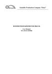
OWNER'S MANUAl
Model No, 831.287602
Serial No.
The se,_alnumber can be found in the
location shown below. Write the serial
number in the space above.
Serial Numbec" Decal
E_X
E:Q
U
E_ R
I P
C I S I___
M
E_ N'[-
H EhPLI
l - 800-
N
7;36-
E.!
5879
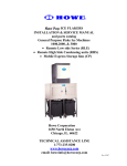
CAUTION!
Read all safety precautions and
instructions in this manual before
using this equipment. Keep this
manual in a safe place for future
reference.
PATENT PENDING
SEARS, ROEBUCK h,ND CO., HOFFM/AN ESTATES, IL 60179
TABLE OF CONTENTS
IMPORTANT
SAFETY PRECAUTIONS
°
..............................
_.-,
ASSEMBLY ......................
_ ...............................................
ADJUSTMENT AND OPERATION .....................................................
TROUBLE-SHOOTING
AND MAINTENANCE ...................................................
CONDITIONING GUIDELINES ...............................................................
PART LIST ...............................................................................
EXPLODED DRAWING .....................................................................
ORDERING REPLACEMENT PARTS ...................................................
LIMITED WARRANTY ..............................................................
IMPORTANT
2
,-:_ o.;:-___
.__o ,-_'-"
._ -. __: !_2
..........
: .......
,. 4
8
11
12
14
15
Back Cover
Back Cover
SAFETY PRECAUTIONS
WARNING: To reduce the risk of serious injury, read the following
using the exercise bike.
1.
Place the exercise bike on a level surface. Do
not use the bike near water or outdoors.
2.
Use the exercise bike only as described in this
manual.
3.
Keep small children away from the exercise
bike at all times.
4.
:
Wear appropriate clothing when exercising;
do not wear loose clothing that could become
caught in the exercise bike. Always wear
athletic shoes for foot protection.
5o
6.
important safety precautions before
When connecting the link arms to'the pedals
(see HANDLEBAR OPERATION on page 8),
make sure that the link arms are on the pedal
bushings. If the link arms are not on the pedal
bushings, they may slip off during use,
resulting in injury.
When adjusting the seat, at least two inches of
the seat post must be inside of the frame. The
seat pin must be inserted from the front, as
shown on page 3. If the seat pin is inserted
from the back, it may slip out during use,
resutting in injury.
WARNING: Before beginning this or any exercise program, consult your physician. This is especially
important for persons over the age of 35 or persons with pre-existing health problems. Read all
instructions before using this product. SEARS assumes no responsibility for personal injury or property
damage sustained by or through the use of this product.
BEFORE YOU
....
' Congratulations for se!ecting the .SEARS. _ '_,,_-:__:
LIFESTYLEF_ C 760 exemisebil<e_ c_yding-isbneoi
the most effective exercises known for increasing
cardiovascular fitness, building endurance and toning
the entire body. The sophisticated LIFESTYLER C 760
offers an impressive array of features to let you enjoy
this healthful exercise in the convenience and privacy
of your home.
For your safety and benefit, read this manual
carefully before using the exercise bike. If you have
additional questions, please call our Customer Service
Departmenttqll-fme at.1-800:736-6879, Monday ....
through Saturdayl 7 a-m.until 7 p.m. Central Time
(excluding holidays). To help us assist you, please
mention the product model number and sedal number
when calling. The model number is 831.287602. The
sedal number can be found on a decal attached to the
exercise bike (see the front cover of this manual for the
location ot the decal).
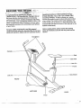
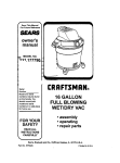
Before reading further, please review the drawing
below and familiarize yourself with the parts that are
labeled.
Handlebars
Console
Seat
Seat Post
Seat Pin
Frame
Link Arm
Side Shield
FRONT
LEFT SIDE
BACK
Pedal
3
: :-ASSEMBLY
.....
in assembly. Note: Some of the small parts used in _.-
Place all pa_rtsof the exemise bike in a cleared area
and remove th'_'l_.cking m_t_ials: DSh0t clisp6se_'
of the packing materials until assembly is completed.
assembly may_ha(ielbeeh p_'e-attached to one Of the
parts to be assembled. If a part is missing, see the.
back cover of this manual for instructions.
Read all steps and examine all drawings carefully
before beginning.
In addition to the tools included, the following
tools are required for assembly:
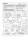
Use the part chart below to identify the small parts
used in assembly. The number in parenthesis
beneath each part refers to the key number of the
part. The second number refers to the quantity used
one (1) hammer £-------_
one (1) adjustable wrench
f
11/16" Spring Washer (51)-2
5/8"
=lastic Cap (3)-2
5/8" Spacer (57)-2
Pedal Spring (52)-2
5/8" Handlebar Spacer (76)-2
11/16" Washer (54)-2
9/16" Washer (56)-2
5/
9/16" Pedal Spacer (75)-2
)-2
1/2" Nylon Lock Nut (
Pedal Bushing
Link Arm Bushing
5/16" Pedal Nut (49)-2
4
5/16" x 1 1/4" Bolt (14)-4
1/4" Seat Nut (7)-4
G
3/4" Phillips Screw (4)-4
_
(55)-2
(58)-_
5/16" x 1/2" Screw (33)-2
5716" x 1 3/4" Bolt (36)-2
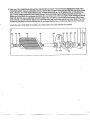
,1_Ra_sethe
back end of the eX_mise bike. Attach the Stabilizer (13)
_. ,..::
i;-_i0'tlie'Frame (11) with the foul: 5/16 x 1 1/4 Bolts (14).The .,-, ,!:.
_:: :-;_'_:'_i
_ _Siabilizer must be tt_med so the ribbed Sides of the Endcaps (12).
"_:_ • _
are on the stde shown! Lo_et the exercise bike. : : ....
I
" "
'.....
'/!
"
"
i
13
2. Slide the free end of the Roller Axle (42) through the Bushings
(43) in the Frame (11). Press the unattached Roller (24) onto the
end of the Axle. It may be helpful to tap the Roller with a hammer
in o,'der to press it fully onto the Axle.
2
24
11
42
3. Remove the four 1/4" Seat Nuts (7) from the underside of the
Seat (5). Remove the Seat Post (6) from the Frame (11). Attach
the Beat to the top of the Seat Post with the four 1/4" Seat Nuts.
3
6
Insert the Seat Post (6) into the Frame it 1), adjust the Seat (5) to
the desired height, and ir_sertthe Seat Pin (8) through the front of
the Frame and the Seat Post. Slide the Seat Post Collar (30)
down over the Frame. CAUTION: At least two inches of the
Seat Post must be inside of the Frame. The Seat Pin must be
inserted from the front, as shown. If the Seat Pin is inserted
from the back, it may slip out, resulting in injury.
4.
Connect the wire protruding from the Console Mount (2) to the
Wire Harness (66) (see the inset drawing). Make sure that the
wire is turned so it fits easily into the Wire Harness. If the wire is
not turned correctly and is forced into lhe Wire Harness, the
Console (1) will not function properly.
Wire
Slide the Console Mount (2) onto the Frame (11). CAUTION: Be
careful to avoid pinching your fingers or the Wire Harness
(66). Attach the Console Mount to the Frame with the two 5/16" x
1/;_"Screws (33).
R
•
.•
°
5. Piug the P_-ei" Co_ (70)into _eja¢l_, #t the back of the _Fe_';,
; bike. Test the console in the foLlowing'manner: _:.:_t_._Y,i_'._,? ii: _!
:
:..-_,
_:_;_-.,_ _-_v_:_:_._:-!_:::.
_ -_ _._,:;.._o'_,_s..._,_-;_,_'_,'_
_
: A.Pl'_gthetransf0_r0,ithepowe_Cord_O)intoa:l20:v01_
!;_._,;
5_ . "_-!! ;_: .
'=;::;_!_!:
:
_. ".-.,.,,:...... ..............
-: ::_-- ,. :: .
B. Press the power button on the console (see the drawing at the
top of page 9). The manual mode indicator will light and the
LCD display will appear. Next, move the manual resistance
control. You will hear the motor as the resistance changes.
Next, press the progranV'manual button. The program mode
Indicator and the eight segment indicators will light.
If the console does not function as descdbed, see assembly step
4. Make sure that the wire is plugged correctly into the wire
harness,
7O
6. Slide a 5/8" Spacer (57) and a 5/8" Handlebar Spacer (76) onto
each side of the handlebar shaft of the Frame (t 1). The open side
of each 5/8" Spacer (57) must be turned toward the Frame.
67
Slide the Left and Right Neck Shields (67, 68) onto the handlebar
shaft of the Frame (11). Insert the four 3/4" Phillips Screws (4)
into the Left Neck Shield, and tighten them into the Right Neck
Shield.
7. Slide a Handlebar (9) onto the left side of the handlebar shaft of
the Frame (11). Tap a 5/8" Plastic Cap (3) onto the handlebar
shaft.
7
Attach the other Handlebar in the same manner (not shown).
8. Insert a 5/16" x 1 3/4" Bolt (36) through the lower end of the left
Handlebar (9). CAUTION: The lower end of the Handlebar may
have a rough edge. Be careful to avoid cutting your fingers.
Tap a Link Arm Bushing (58) into a Unk Arm (37). Slide the Unk
Arm onto the Bolt. The flange of the Link Arm Bushing must be
turned toward the Handlebar, and the opening in the end of the
Unk Arm must be downward as shown. Tighten a 5/16" x 18 Nut
(17) onto the Bolt. Do not ovedighten the Nut; the Link Arm must
pivot freely. Clip the Link Arm onto the lock rod.
Attach the other Link Arm to the right Handlebar in the same
manner (not shown).
6
Lock
Rod
17
9. Hold one of the Pedal Shafts (38) with the included tool as shown---the tool must be between the coils of the
Pedal Spdng (52). Using an adjustable wrenoh, remove the 1/2" Nylon Lock Nut (46) f_n"tll_
end of the Peda
Shaft. (There is an 11116" Spdng Washer (51), a Pedal Spring (52), an 11/16" Washer 154), a Pedal Bushing
155), a 9/'16" Washer (56) and a 9/16" Pedal Spacer (75) on the Pedal Shaft.) Using the included tool, _rmty :t__.._T,
_
tighten the Pedal Shaft, In a clockwise direction, into one of the arms of the Crank 127). While holding the Pedal
Shaft with the tool, use an adjustable wrench to tighten the 1/'2" Nylon Lock Nut (46) onto the end of the Pedal
Shaft. (There is a 5/16" Washer (65) and a 5/16" Pedal Nut (49) on the other end of the Pedal Shaft. The 5116"
Pedal Nut (49) must be flush with the end of the Pedal Shaft.) Press a Pedal Cap (50) into the Pedal (10).
Attach the other Pedal Shaft to the other arm of the Crank in the same manner (not shown).
9
)
55
49
52
66 . 75
Tool
7
ADJUS'F ENT
CONNECTING
AND OPERATION
THE POWER CORD ::_ !'__'_
" "" " ";:
.....
- _; - " :" " "
"_ _ ;" " .........
=
_ :
Plug the transformer Onthe power cord into a 120-volt outlet. Keep the power cord away from walkways and
. heated surfaces. Turn on the power when using the exercise bike orthe bike could be damaged.
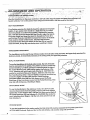
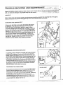
SEAT ADJUSTMENT
For effective exercise, the Seat (5) should I_e adjusted to the proper
height. AS you pedal, there should be a slight bend in your knees
when the pedals are at the lowest position. Dismount the exercise
bike. Hold the Seat and remove the Seat Pin (8). Adjust the Seat to
the proper height and insert the Seat Pin through the Frame (11)
and the Seat Post (6). CAUTION: At least two inches of the Seat
Post must be inside of the Frame. The Seat Pin must be
inserted from the front, as shown. If the Seat Pin is inserted
from the back, it may slip out during use, resulting in injury.
HANDLEBAR
OPERATION
The handlebars can be used in any of three modes: the dual-action mode, for lower- and upper-body exercise; the
stationary mode, for lower-body exercise; or the rowing mode, for upper-bodyexercise.
DUAL-ACTION MODE
To use the haodlebars in the dual-action mode, the Link Arms (37)
must be connected to the pedals. First, lift the Link Arms off the lock
rod (see drawing 1). Pull the Link Arms outward against the tops of
the 11/16" Washers (54), while pulling against the bottoms of the
11/16" Washers with your fingers (see drawing 2). CAUTION: Be careful to avoid pinching your fingers. Slide the Link Arms onto
the Pedal Bushings (55). It may be helpful to move the Link Arms up
and down slightly until they slide onto the Pedal Bushings.
CAUTION: Make sure that the Link Arms are on the Pedal
Bushings. If the Link Arms are not on the Pedal Bushings, they
may slip off during use, resulting in injury.
STATIONARY
Lock Rod
2
MODE
To use the handlebars in the stationary mode, the Link Arms (37)
must be disconnected from the pedals. Pull the Link Arms outward
against the 11/16" Washers (54), until the Link Arms can be lifted off
the Pedal Bushings (55) (see drawing 2). CAUTION: Be careful to
avoid pinching your fingers. Clip the Link Arms onto the lock rod
(see drawing 1).
54
ROWING' MODE
To use the handlebars in the rowing mode, the Link Arms (37) must be connected to the pedals (see DUALAC_ ON MODE above). Rest your feet on the side shields, and exercise using only your arms.
8
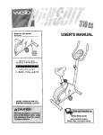
DIAGRAM OF THE CONSOLE
V
35
30
25
20
15
•
Power
i
DESCRiPTiON
OF THE CONSOLE
The heart of the exercise bike is the programmable
console. The console offers both manual and progrem
modes, and features a multiple-mode exercise monitor
to provide you with Instant feedback during your
workouts. Remove the clear plastic film from the front
of the console. Please read these instructionscarefully
before operating the console.
TURNING ON THE POWER
To turn on the power, press the power button or simply
begin pedaling. The manual mode indicator will light
and the LCD display will appear.
MANUAL MODE
When the power is turned on, the console will be in the
manual mode. As you pedal, the pedaling resistance
can be changed by moving the manual resistance
control. To increase'lhe resistance, move the control
upward; to decrease the resistance, move the control
downward. After the control is moved, it will lake a few
seconds for the exercise bike to reach the selected
resistance setting.
PROGRAM MODE
When the console is in the program mode, the pedaling
resistance will be controlled by programs you create.
Each program will consist of eight equal time periods,
called segments. The resistance will change
automatically at the beginning of each segment. To
create a program, a resistance setting should be
programmed for.each of the eight segments by moving
the eight program resistance controls on the left side of
the console. The control at far left is for the first
segment, and the control at far right is for the eighth
Segment. To program resistance settings, move the
controls to the desired positions. The higher the
controls are moved, the higher the resistance settings
will be. A sample program is shown above. This
program WIUbegin with a low resistance setting. The
resistance will then increase dudng the second and
third segments, decrease during the fourth segment,
increase again during the fifth and sixth segments, and
decrease during lhe seventh and eighth segments. An
infinitevariety of settings can be programmed.
Next, move the program time control to set the length
of time you want the program to last. The program can
be set to last for a minimum of 5 minutes, up to a
maximum of 35 minutes.
To start the program, press the program/manual button
and begin pedaling. The program mode indicator and
the first eight segments will light, and the exercise bike
will automatically adjust to the setting of the first
program resistance control. Alter one-eighth of the
length of time you set has elapsed, the first segment
indicator will darken, and the exercise bike will automatically adjust to the setting of the second program
resistance control. The program will continue in this
manner until all eight segment indicators are dark.
While the program is in progress, the pedaling resistance can be changed during the current segment, if
desired, by moving the program resistance control for
the current segment. If desired, the program can be
stopped or the console can be switched to the manual
mode by pressing the program/manual button.
9
EXERCISE MONITOR MODES
EXERCISE MONITOR OPERATION
:-The exercise monitor features five different modes: _.::-_ whenthe power is turned 0n, _he SCAN mode wi) be "_:_"
belected automatically; One mode indicator will appear:
SPEED--Displays _ou?p_daling speed, in miles per "
y t_e'word "SCAN." The SPEED, TIME, DISTANCE
hour..:
......
and CALORIE modes Willbe displayed in a repeating
cycle. A second mode indicator will show which mode
TIME--Displays the elapsed time. Note: Time will be
is currently displayed.
counted only while you are pedaling, if you stop for ten
If desired, the SPEED, TIME, DISTANCE or CALORIE •
seconds or longer, the TIME mode will hold until you
resume pedaling.
mode can be selected for continuous display by
repeatedly pressing the display mode button. The
DISTANCE--Displays
the total distance you have
modes will be selected in the following order:.SPEED,
pedaled, in miles.
TIME, DISTANCE, CALORIE, SCAN.
CALORIE--Displays
the total number of Calodes you
have burned. Note: If the pedaling resistance is near
the.lowest or highest setting, the actual number of
Calodes you have burned will be slightly lower or
.-higher than the number displayed.
SCAN--Displays the SPEED, TIME, DISTANCE and
CALORIE modes, for five seconds each, in a repeating
cycle.
10
To reset the LCD display, turn the.power off end then
on again by pressing the power button twice.
TURNING THE POWER OFF
When you am finished exercising, press the power
button to turn the power off. Note: li' the pedals are not
moved end the controls are not used for four minutes,
the power will turn off automat[celly.
TROUBLE-SHOOTING
AND MAINTENANCE
,.,;,
-
Inspect and tighten all parts regularly. _uter surfaces of the exercise bike can _ _,ea,n_d using a dam_:c/o_iar_d
i
m Id, non-abras ve detergent Keep liquids away from the console '.':'
"' :-_;",_;!:' _;' _._" _._i-e-._ _;!_.!__ ,_:_:-i
CONSOLE
If the console does not function properly, the wire harness should be checked. See assembly step 4 on page 5.
Make sure that the wire harness is plugged fully into the wire extending from the console.
ADJUSTING THE TENSION BELT
If the tension belt slips as you pedal, the tension belt should
be tightened. First, disconnect the Link Arms (37) from the
Pedals (10) (see STATIONARY MODE on page 8). Next,
remove the Pedals (see assembly step 9 on page 7). Remove
the four 3/4" Phillips Screws (4) from the Left and Right Neck
Shields (67, 68). Remove the #8 x 1" Screws (15) and the 3/4"
Tec Screws (69) from the Left and Right Side Shields (16, 34).
Slide the Side Shields off the exercise bike. To tighten the
tension belt, turn both of the 3/8" Flange Nuts (18) clockwise
one full turn• Repeat until the tension belt no longer slips.
Reattach the Side Shields, Neck Shields and Pedals.
15
15
69
CENTERING THE TENSION BRACKET
If a grinding noise is heard as you pedal, the Tension Bracket
(35) should be adjusted. Disconnect the link arms from the
pedals, remove the pedals, and remove the side shields (see
ADJUSTING THE TENSION BELT above). Hold the 3/8" x 16
Nylon Lock Nut (73) with a wrench. If the Tension Bracket is
touching the right side of the Resistance Disk (22), turn the
Tension Bracket.Bolt (60) clockwise until the Tension Bracket
is centered. If the Tension Bracket is touching the left side of
the Resistance bisk_tum the Bolt counterclockwise. Reattach
the side shields, neck shields and pedals.
TIGHTENING
.T..o#.
V,ew
...-"
THE CRANK ARMS
left side shield
If the crank arms become loose, they should be tight-ened in
order to prevent excessive wear. Loosen the hex nut on the
left arm of the Crank (27). Place the end of a standard
screwddver in one of the grooves in the crank nut. Lightly tap
the screwdriver with a hammer to turn the crank nut
counterclockwise, until the crank arms are no longer loose•
Do nqt overtighten the crank nut. When the crank nut is
propedy tightened, tighten the hex nut.
crank
27
hex nut
11
CONDITIONING
GUIDELINES
....
The foltowlng guidelines will help you to plan your
exercise program. Remember that proper nutrition"and
adequate rest are essential for successfulresults.
WARNING: Before beginning this or any exercise
program, consult your physician. This is especially
important for persons over the age of 35 or
persons with pre-existing health problems.
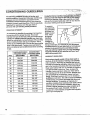
EXERCISE INTENSITY
To maximize the benefitS of exercising, it is important
to exercise with the proper intensity. The proper
intensity level can be found by using your heart rate as
a guide. For effective aerobic exercise, your heart rate
should be maintained at a level between 70% and 85%
of your maximum heart rate as you exercise. This is
known as your training zone. You can find your training
zone in the table below, Training zones are listed for
both unconditioned and conditioned persons according
to age.
AGE
UNCONDITIONED
TRAINING ZONE
(BEATS/MIN
• 20
132-_160
30
'"
• 135-164
130-158
35
:
134-162
129"156
.... 132"161 ........
_.
........
.
_,_,. _'_._, "
To measure
your heart rate,
stop exercising
and place two
fingers on your
wrist.Take a
six-second
heartbeat
count, and
multiply the
result by 10 to
find your heart rate. For example, if your six-second
heartbeat countis 14. your heart rate is 140 beats per
minute. {A six-second count is used because your
heart rate will drop rapidlywhen you stop exercising.)
Adjust the intensityof your exercise until your heart
rate is at the proper level.
WORKOUT GUIDELINES
.133-162
25 "" ! _"-. 136-'166
.40
12
"138-167
CONDITIONED
TRAINING ZONE
(BEATS/MIN
...._
Ounng the first few months of y_o_ur
exemise program _..
keep your head rate near the low end of your tra_n=ng"r
zone as you exemise. After a few months, your heart
rate can be increased gradually until it is near the middle of your training zone as you exemise.
127"155
45
131 "159
125"153
50
129-156
124-150
55
127"155
122"149
60
126-153
121 "147
65
125-151
119-145
' 70
123"150
118-144
75
122-147
117-142
80
120-146
115-140
85
118-144
114-139
Each workoutshould consist of three basic pads: a
warm-up, 20 to 30 miautes of training zone exercise,
and a cool-down. Warming up prepares the body for
exercise by increasingcirculation, delivering more oxygen to the muscles and raising the body temperature.
Begin each workout with 6 to 10 minutes of stretching
and IIgh_exercise to warm up. Then, increase the
intensityof y(_urexercise to raise your heart rate to
your training zone for 20 to 30 minutes. B_eathe regularly and deeply as you exercise--never hold your
breath. Finish each workout with 5 to 10 minutes of
stret'ching to cool down. This will increase the flexibility
of the'muscles, and reduce soreness and other postexercise problems. To maintain or improve your
condition,complete three workouts each week, with at
least one day of rest between workouts. After a few
monthsof regularexercise, you may complete up to
five workoutseach week, if desired. The key to
success is to make exercise a regular and enjoyable
part of your everyday life.
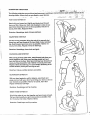
SUGGESTED
STRETCHES....
•.
"
..,._
::
,. .......
'.
_.:_
_*:,_!,:_--:..:_:._,;'_,_
.
,_ , ;_ ._. ,.
The followingstretches can provide a good warm-up or cooFdown. Correct form for each stretch is shown in the
....
;:F_ .
._.
drawings below. Move slowly as you stretbl_-never bounce. •
....
;_!_:.-TOETOUCH
•
:
STRETCH
Stand with your knees bent slightly and slowly bend forward
from your hips. Allow your back and shoulders to relax as you
• reach down toward your toes as far as possible. Hold for 15
' counts, then relax. Repeat 3 times.
Stretches: Hamstdngs, back of knees and back.
HAMSTRING STRETCH
Sit with one leg extended. Bdeg the sole of the opposite foot
toward you and rest it against the inner thigh of your extended
leg. Reach toward your toes as far as possible. Hold for 15
counts, then relax. Repeat 3 times for both legs.
Stretches: Hamstrings, lower back and groin.
CALF/ACHILLES STRETCH
With one leg in front of the other, reach forward and place your
hands against a wall. Keep your back leg straight and your
back foot flat on the floor. Bend your front leg, lean forward and
move your hips toward the wall. Hold for 15 counts, then relax.
Repeat 3 times for both legs. To cause further stretching of the
achilles tendons, bend your back leg as well.
Stretches: Calves, achilles tendons and ankles.
QUADRICEPS STRETCH
With one hand against a wall for balance, reach back and
grasp one foot with your other hand. Bring your heel as close to
your buttocks as possible. Hold for 15 counts, then relax.
Repeat 3 times for both legs•
Stretches: Quaddce.ps and hip muscles.
INNER THIGH STRETCH
Sit with the soles of your feet together and your knees outward.
Pull your feet toward your groin area as far as possible. Hold
for 15 counts, then relax. Repeat 3 times•
Stretches: Quadriceps
and hip muscles.
13
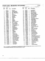
PART LIST--Model
Key
No.
•1
2
3
4
5
6
7
8 .
9
10
11
12
13
14
15
16
17
18
19
20
21
22
23
24
25
26
27
28
2§
30
31
32
33
34
35
36
37
38
39
40
Part
No..
118731
119456
100151
013510
105022
116605
012096
116675
117009
112701
NSP
105590
116606
013469
013294
122374
012056
012090
113788
113834
113789
119198
113791
106697
113954
119200
101115
113783
115777
104786
114113
108667
013484
122375
113792
013250
116607
112779
100076
105500
No. 831.287602.
':
Qty.
1
1
2
8
1
1
4
1
2
2
1
2
1
4
12
1
2
2
1
2
1
1
1
2
1
1
1
1
1
1
1
4
2
1
1
2
2
2
1
2
, Description
Console
Console Mount
5/8" Plastic Cap
3/4" Phillips Screw
Seat
Seat Post
1/4" Seat Nut
Seat Pin
Handlebar
Pedal
Frame
Endcap
Stabilizer
5/16" x 1 1/4" Bolt
#8 x 1"Screw
Left Side Shield
5/16" x 18 Nut
1/4" Nylon Lock Nut
Small Spacer
Beadng
Large Spacer
Resistance Disk
Flywheel Axle
Roller
Flywheel
Lock Ring
Crank
Tension Belt
Tension Pulley
Seat Post Bushing
Tension Rope
Handlebar Bushing
5/16" x 1/2" Screw
Right Side Shield
Tension Bracket
5/16" x I 3/4" Bolt
Link Arm
Pedal Shaft
Small Spring
Foam Grip
Key"
No.
41
42
43
44
45
46
47
48
49
50
51
52
53
54
55
56
57
58
59
60
61
62
63
64
65
66
67
68
69
70
71
72
73
74
7_"
76"
#
#
#
#
#
R 1294A
'Part''! :':";;;
_'_:'_!_"
: '.; ""
No.
Qty. . Description
113781
1
106698
1
106880
2
013423
1
104787
1
100904
2
110465
1
103860
2
012146
2
112704
2
101456
2
103571
2
115778
1
101460
2
101036
2
101494
2
108668
2
100364 • 2
101768
2
104925
1
100498
1
101049
2
012082
2
104536
2
014041
2
118732
1
113833
1
113832
1
107428
6
101067
1
106t 15
1
013300
1
012108
1
106832
2
114109
2
119446
2
101324
1
045028
1
045010
1
016055
4
122839
1
'" =' " ' -
Large Spdng
Roller Axle
Roller Bushing
#8 x 1/2" Screw
Seat Post Glide
1/2" Nylon Lock Nut
Crank Hardware
#4 x 1/2" Screw
5/16" Pedal Nut
Pedal Cap
11/16" Spring Washer
Pedal Spring
Tension Motor
11/16" Washer
Pedal Bushing
9/16" Washer
5/8" Spacer
Link Arm Bushing
3!8" Axle Cap
Tension Bracket Bolt
Magnet
3/16" x 1/2" Screw
5/16" Flange Nut
Eye Bolt
5/16" Washer
Wire Harness
Left Neck Shield
Right Neck Shield
3/4" Tec Screw
Power Cord
Reed Switoh/Sensor Wire
3/4" Self-Tapping Screw
318"x 16 Nylon Lock Nut
5/16" Flat Washer
9/16" Pedal Spacer
Handlebar Spacer
Screwdriver/Wrench
Socket Tool
Allen Wrench
M-Clip
Owner's Manual
Note: "#" indicates a non-illustrated part. Specificationsare subject to change without notice. See the back cover
of this manual for Information about ordering replacement parts.
14
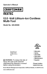
EXPLODEDDRAWING---Model
No. 831.287602
R1294A
32
68
7
15
oO
23
28
13
12
2O
22
19
16
24
4
60
15
-"
51
oO
oO'°38
17
15
""
65
7
50
15
CRANK
HARDWARI=
147't
t _ •
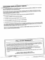
ORDERING
•. :,
REPLACEMENT
PARTS,
Each EXERCISE BIKE has Its _vn MODEL NUMBER. Always mention this MODEL NUMBER when requesting
service or repair parts for your EXERCISE BIKE.
All parts listed herein can be ordered through SEARS, ROEBUCK AND CO. SERVICE CENTERS and most
SEARS RETAIL STORES. If parts you need are not stocked locally, your order will be transmitted to a SEARS
PARTS DISTRIBUTION CENTER for handling.
WHEN ORDERING
REPAIR PARTS, ALWAYS GIVE THE FOLLOWING INFORMATION:
1. The MODEL NUMBER of the product (831.287602).
2. The NAME Of the product (LIFESTYLER ° C 760 exercise bike).
3. The PART NUMBER of the part(s), from page 14 of this manual.
4. The DESCRIPTION
of the part(s), from page 14 of this manual.
Your SEARS merchandise has added value when you consider that SEARS has serv_e units nationwide, staffed
with SEARS trained technicians specifically trained on SEARS products, having the parts, tools and equipment to
ensure that we meet our pledge to you: "We service what we sell."
Should you ever need repair service or pads, cell toll-free: 1-800-736-6879,
until 7 p.m. Central Time (excluding holidays).
I
Monday through Saturday, 7 a.m.
]
FULL 90 DAY WARRANTY
For 90 days from the date of purchase, when proper assembly and maintenance procedures detailed in
this owner's manual are followed, SEARS will, free of charge, repair or replace and install a replacement
part for any defective part, when this exercise bike is used in a normal manner.
This warranty does not apply when this exercise bike is used for commercial or rental purposes.
SERVICE IS AVAILABLE SIMPLY BY RETURNING THE EXERCISE BIKE TO YOUR NEAREST
SEARS SERVICE CENTER/DEPARTMENT
IN THE UNITED STATES.
This warranty gives you specific legal rights, and you may also have other rights which vary from state
to state.
SEARS, ROEBUCK AND CO., DEPT. 817WA,
3333 BEVERLY ROAD, HOFFMAN ESTATES, IL 60179
¢) 1994 Sears, Roebuck and Co.