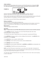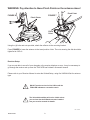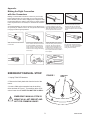
1
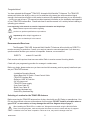
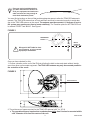
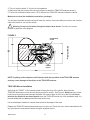
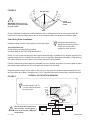
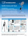
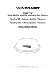
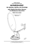
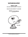
WINEGARD ® TRAV’LER ® Automatic Multi-Satellite TV Antenna Model SK-3005 DIRECTV® SLIMLINE INSTALLATION MANUAL Made in the U.S.A. SK-3005 Winegard Company • 3000 Kirkwood St. • Burlington, IA 52601-2000 319/754-0600 • FAX 319/754-0787 • www.winegard.com Printed in U.S.A. © Winegard Company 2008 2452133 Rev. 1/10 Congratulations! You have selected the Winegard® TRAV’LER Automatic Multi-Satellite TV Antenna. The TRAV’LER antenna will deliver the ability to view up to five satellites at the same time with unmatched signal strength, the lowest travel height on the market, maximum HD capabilities and easy to use functionality – just like you get at home. This manual provides important information on the installation and operation of your TRAV’LER Interface Box. Please take time to read the manual in it’s entirety before installing or operating your antenna. Icons appearing in the manual are used for important information and helpful tips. Alert indicates important information regarding product use, product specifications or procedures. Important tip offers helpful suggestions or refers you to a related topic in the manual. Recommended Receivers: The Winegard® TRAV’LER Automatic Multi-Satellite TV Antenna will work with any DIRECTV® receiver currently in production. Consult your receiver manual or www.winegard.com if you have any questions about whether your receiver is compatible. However, we recommend: DIRECTV : models D11 and H20 Each receiver will require at least one coax cable. Refer to receiver manual for wiring details. Check with your programming provider for coverage in certain areas. Before you begin, please make sure you have received all necessary parts to properly install and operate your TRAV’LER antenna. - Installation/Operation Manual - Mount Base with 30’ Cable - Power/Control Cable - TRAV’LER Interface Box - Reflector, LNBF & Feed Arm - 24” AC power cord - TRAV’LER Power supply - Gray Coax Cable 30’ - Black Coax Cable 30’ - Mounting Hardware bag - Cable Entry Hardware bag Selecting a Location for the TRAV’LER Antenna Before removing the TRAV’LER antenna from its box, check with your RV Dealer or manufacturer. Your RV may be pre-wired or have a reinforced area for this system. DO NOT install in a location where a gap of 3/16” or more exists, as it may damage the roof. See diagram at top of page 3. When installing the TRAV’LER on a rubber roof, Winegard recommends using the SKA-004 Roller Plate. If not using this plate, make sure that the roller does not come in contact with any rib supports or bubbles in the roof when in operation. Failure to do so, may result in damage to the roof. INSTALLATION 2 Plan your entire installation before you start. Determine the location of all of your equipment and make sure cable and wires are long enough to reach their destination points. 3/16” You must find a location on the roof that provides adequate space to allow the TRAV’LER antenna to operate. The TRAV’LER antenna has a Front and Back and must be mounted correctly to avoid damage to the TRAV’LER antenna or the coach. The antenna must be mounted +/-5 degrees of level or the system may require more time to locate satellite(s). The Transition plate for the TRAV’LER unit is marked “FRONT” and “BACK”. See Figure 1. FIGURE 1 Winegard is NOT liable for damage, expenses, or injury caused by improper installation. FRONT OF RV FRONT ! BACK TRANSITION PLATE Mount Parallel to Center Line of Coach Once you have checked for this: 1. Choose a location on the roof of the RV that will allow the dish to raise and rotate without interference from other roof mounted equipment. The TRAV’LER antenna may only be mounted parallel to the centerline of the coach. FIGURE 2 FRONT OF RV Mount Parallel to Center Line of Coach 2. The minimum roof space required for the TRAV’LER antenna is 44” L x 34” W. a. The operational space requires that no obstructions taller than 8 inches be mounted within a 68” diameter circle from the center of the unit. 3 INSTALLATION 3. The unit must be within 3° of level for best operation. 4. Make sure that the location offers enough support to attach the TRAV’LER antenna securely. 5. Find a well ventilated location with a 110 V outlet for the TRAV’LER Interface inside the vehicle. Make sure to clean the installation area before you begin. You will want to decide where the wires will enter the vehicle. One coax cable per receiver and a control cable will need to be run into the vehicle. ! Warning: Do not run the wires through the striped area shown. Consult your receiver manual for specifics in the diagram. FIGURE 3 TRANSITION PLATE FRONT OF RV FRONT 18 inches 24 inches SCREW HOLES NOTE: Anything in the striped area will interfere with the operation of the TRAV’LER antenna and may cause damage to the object or the TRAV’LER antenna. TRAV’LER Mount Installation Verify that the “FRONT” of the transition plate is facing the front of the vehicle, then place the TRAV’LER antenna mount on the roof where you plan to install it. See Figure 3. Mark where the screw holes will go by placing marks through the holes in the mount base on the roof of the RV. It is important that you be able to see these marks! Move the TRAV’LER mount out of the installation area. It is recommended that you don’t pre-drill the holes at this time. Use a solid bead of sealant to connect these marks in the shape of the base. Replace the TRAV’LER antenna base and screw it to the roof. Check with your vehicle manufacturer for any special screw requirements before using the supplied screws. INSTALLATION 4 FIGURE 4 DO NOT SEAL ! LIP OF TRANSITION PLATE WARNING: DO NOT cut any wires when you drill the hole for your cables. SEAL Run a solid bead of sealant around the transition plate, making sure to cover each screw head. Be careful not to get any sealant above the lip of the transition plate. See diagram of transition plate. Cable Entry Plate Installation: Winegard recommends installing the Accessory Detect Cable, this can provide a emergency stow function. Decide the best location for the cables to enter the vehicle. You will need to run: A coax directly to each receiver location. A control cable to the TRAV’LER Interface box. Drill a 1/2” hole in the roof and push the required wires through. (Installations for multiple receivers may require a larger hole or multiple holes as each receiver requires a dedicated coax cable.) Each receiver will require at least one coax cable. See receiver manual for wiring details. Place the cable entry plate supplied in hardware bag over the hole and cables. Screw the plate in place and seal the plate and screw holes with approved sealant (not included). Depending on the length of the cable on the roof, you may need to use cable clamps between the unit and your cable entry plate. Clamping every 12-16” should eliminate any unnecessary cable movement. FIGURE 5 OVERALL INSTALLATION DRAWING FRONT OF RV For best results, use TV 1 for the receiver that will be most active. POWER SUPPLY IDU A B POWER C ENTRY PLATE RECEIVER ! Rev. 4/15/08 The SK-3005 will support up to four receivers. It can support more receivers with a DIRECTV® multi-switch. TV 1 RECEIVER RECEIVER TV 3 TV 2 5 INSTALLATION Cable installation: Connect the control cable and power cable to the back of the TRAV’LER Interface box as shown below. Note: For cable runs longer than 25’ an extension may be purchased. Do not exceed 50’ of cable. Power ` Control Cable ` FIGURE 5A Attach the TRAV’LER control cable to the TRAV’LER Interface Box, as shown in Figure 5A. Attach the output cable from the Power supply to the TRAV’LER Interface Box. See above. Finally, connect a coax cable from the TRAV’LER mount to each of the receivers being used with the TRAV’LER Automatic Satellite Dish. See Appendix for information on properly installing a Hex Connector. Find a location to plug in the TRAV’LER Power supply and plug it in. Reflector Installation: Once the wires are run and the sealant has started to cure: Check to be sure that there is nothing above the TRAV’LER that might prevent it from raising. You will need at least 40” of clearance above the TRAV’LER Mount to ensure that you have room to install the reflector. Raise Antenna: There are two ways to raise the antenna. Automatic: Steps 1-7 explain how to use the TRAV’LER Interface box to raise the mount to install the reflector. 1. Press [POWER] and hold for 2 seconds to turn “ON” the TRAV’LER Interface Box. Wait until the Interface Box finishes “connecting to antenna”. * The TRAV’LER may enter the “Search Routine” after 10 seconds this is normal (See NOTE Below). 2. Press [ENTER] and hold for 2 seconds or until the unit displays “Enter User Menu”. Press [SELECT] to move the asterisk to “Yes”. Press [ENTER]. 3. Press [SELECT] to move the asterisk to INSTALLATION. 4. Press [ENTER]. You will be asked to provide a code to enter the Installation Menu. 5. Press [ENTER] 4 times to enter code 0000. 6. Press [SELECT] to move the asterisk to RAISE DISH. Press [ENTER]. Press [SELECT] to move the asterisk to Yes. 7. Press [ENTER] the TRAV’LER mount will raise up about half way. NOTE: If the TRAV’LER enters the “Search Routine” you can still enter the “Menu Mode”. See Steps A & B. If the TRAV’LER Mount raises past 1/2 way before RAISE DISH is selected (See Step 6), the TRAV’LER will hit its Upper Hard Stop and “Motor Stall” appears. This is Normal. The “Motor Stall” means the TRAV’LER is all the way up & mount can raise no more. There are two easy ways to clear the “Motor Stall”. INSTALLATION 6 A. Press [ENTER] the TRAV’LER will return to the “Installation Menu” OR B. Press [POWER] the TRAV’LER will stow and turn “OFF” (Restart at Step 1). 1. Press [POWER] and hold for 2 seconds to turn “ON” the TRAV’LER Interface Box. Wait until the Interface Box finishes “connecting to antenna”. * The TRAV’LER may enter the “Search Routine” after 10 seconds this is normal (See NOTE Below). 2. Press [ENTER] and hold for 2 seconds or until the unit displays “Enter User Menu”. Press [SELECT] to move the asterisk to “Yes”. Press [ENTER]. 3. Press [SELECT] to move the asterisk to INSTALLATION. 4. Press [ENTER]. You will be asked to provide a code to enter the Installation Menu. 5. Press [ENTER] 4 times to enter code 0000. 6. Press [SELECT] to move “ * ” to “Calibrate EL”. 7. Press [ENTER]. 8. Press [SELECT] to move “ * ” to YES. 9. Press [ENTER] to start the elevation calibration procedure. The LCD should now display “ Calibrate EL In Progress ...”. 10. After a few moments the IDU LCD will display “On EL Hard Stop?-Yes *No”. Visually examine the antenna to verify that the antenna is against the Hard Stop. The antenna will be pointing as far up as it can go, this is the Hard Stop. 11. Press [SELECT] once to move asterisk to “Yes” if antenna is on the Hard Stop. 12. Press [ENTER] and the LCD will display “Calibrate EL Success”. 13. You may now stow the antenna. 7 INSTALLATION WARNING: Pay attention to these Pinch Points as the antenna raises! FIGURE 6 FIGURE 7 Pinch Points Pinch Point Pinch Point Using the (4) bolts and nuts provided, attach the reflector to the mounting bracket. Press [POWER] to lower the antenna to the travel position. Note: The nuts securing the dish should be tightened to 6-8 lb.ft. Receiver Setup: If you are not able to see all of your channels or the receiver displays an error, it may be necessary to go through the receiver set up once the TRAV’LER has finished a successful search. Please refer to your Receiver Manual to enter the Guided Setup, using five LNB Multi-Sat for antenna type. ! ! DO NOT set the receiver for five LNB’s until the TRAV’LER indicates a successful search. The 103 and 99 satellites will not be visible unless your reciever has the B-Band converter installed. See your receiver manual for details. Rev. 4/15/08 INSTALLATION 8 Appendix: Making the Right Connection with Hex Connectors Making a coaxial cable connection is critical. If you have the basic technique right you can modify it to your own personal taste. Whether you use a knife, stripping tool or diagonal cutter, the important thing is to make a good clean cut. A hex crimping tool is required for hex connectors, for maximum RF transmission. As mentioned before, the choice of tools is yours. Be sure you do a precise job. Failure to do so can cost you time and money in trying to locate a system problem. Slide connector onto coax. Trim off excess braid. Cut the cable flush. Strip the outer jacket off 1/2”, then trim the dielectric by cutting partially thru. DO NOT NICK THE CENTER CONDUCTOR! Twist and pull off leaving a 1/2” minumum of exposed center conductor. IN HOT WEATHER: Trim off center conductor leaving 3/16” beyond the connector. The center conductor expands at higher temperatures. If a little extra is not provided, it may contract enough in the winter to create an open connection and result in loss of picture. Look into end of connector to make sure no braid or aluminum foil touches or has the possibility of touching the center conductor. Shorting can result if either comes in contact with center conductor. Close crimping tool making correct crimp. EMERGENCY MANUAL STOW FIGURE 1 1. Unplug TRAV’LER Interface. Remove additional 1/4” of the outer jacket.Pull the braid away from the dielectric and fold over the jacket. If there’s any residue on the center conductor scrape off with non-metallic object. IN COLD WEATHER OR INDOORS: Trim off center conductor leaving it extended 1/16” of an inch beyond the connector. (Use diagonal pliers for cutting center conductor). AUXILIARY DRIVE 2. Remove the black plastic bolt from the back of the mount. 3. Insert a 3/8th socket extension into the auxiliary drive as shown in Figure 1. Turn auxiliary drive clockwise to lower the unit. NOTE: DO NOT USE A DRILL. ! EMERGENCY MANUAL STOW IS MEANT AS A LAST RESORT AND NOT FOR COMMON USAGE! 9 INSTALLATION WINEGARD MOBILE PRODUCTS LIMITED WARRANTY (2 YEARS PARTS; 1 YEAR LABOR) Winegard Company warrants this product against defects in materials or workmanship for a period of two (2) years from the date of original purchase. During year one (1) of such warranty, Winegard Company will also pay authorized labor costs to an authorized Winegard dealer to repair or replace defective products. No warranty claim will be honored unless at the time the claim is made, Customer presents proof of purchase to an authorized Winegard dealer (to locate the nearest authorized Winegard dealer, contact Winegard Company, 3000 Kirkwood Street, Burlington, Iowa 52601, Telephone 800-288-8094 or visit www.winegard.com). Customer must provide proof of purchase with a dated sales receipt for the Winegard product to verify the product is under warranty. If the date of purchase cannot be verified, the warranty period shall be considered to begin thirty (30) days after the date of manufacture. If a defect in material or workmanship is discovered, Customer may take the product to an authorized Winegard dealer for service. Customer must provide proof of purchase to verify the product is under warranty. If the product is brought to an authorized Winegard dealer for service prior to expiration of year one (1) of the warranty period and a defect in material or workmanship is verified by Winegard Technical Services, Winegard Company will cover the Winegard dealer’s labor charges for warranty service. The Winegard dealer must contact Winegard Technical Services in advance for pre-approval of the service. Approval of the service is at the sole discretion of Winegard Company. Alternatively, Customer may ship the product prepaid to Winegard Technical Services (located at 3111 Kirkwood Street, Burlington, Iowa 52601, Telephone 800-788-4417). Customer must return the product along with a brief description of the problem and provide Winegard Technical Services with Customer’s name, address, and phone number. Customer must also provide proof of purchase to verify the product is under warranty. If the product is returned before the expiration of the warranty period, Winegard Company will (at its option) either repair or replace the product. This Limited Warranty does not apply if the product has been damaged, deteriorates, malfunctions or fails from: improper installation, misuse, abuse, neglect, accident, tampering, modification of the product as originally manufactured by Winegard in any manner whatsoever, removing or defacing any serial number, usage not in accordance with product instructions or acts of nature such as damage caused by wind, lightning, ice or corrosive environments such as salt spray and acid rain. This Limited Warranty also does not apply if the product becomes unable to perform its’ intended function in any way as a result of the television signal provider making any changes in technology or service. RETURN AUTHORIZATION POLICY A Return Material Authorization (RMA) is required prior to returning any product to Winegard Company or Winegard Warranty Services under this warranty policy. Please call our Technical Services Department at 800-788-4417 or send an e-mail to [email protected] to obtain the RMA number. Please furnish the date of purchase when requesting an RMA number. Enclose the product in a prepaid package and write the RMA number in large, clear letters on the outside of the package. To avoid confusion or misunderstanding, a shipment(s) without an RMA number(s) or an unauthorized return(s) will be refused and returned to Customer freight collect. WINEGARD COMPANY DOES NOT ASSUME ANY LIABILITIES FOR ANY OTHER WARRANTIES, EXPRESS OR IMPLIED, MADE BY ANY OTHER PERSON. ALL OTHER WARRANTIES WHETHER EXPRESS, IMPLIED OR STATUTORY INCLUDING WARRANTIES OF FITNESS FOR A PARTICULAR PURPOSE AND MERCHANTABILITY ARE LIMITED TO THE TWO YEAR PERIOD OF THIS WARRANTY. In states that do not allow limitations on implied warranties, or the exclusion of limitation of incidental or consequential damages, the above limitations or exclusions do not apply. Some states do not allow limitations on how long an implied warranty lasts, or the exclusion of limitation of incidental or consequential damages, so the above limitations or exclusions may not apply to you. This warranty gives Customer specific legal rights. Customer may also have other rights that may vary from state to state. SATELLITE RECEIVER WARRANTY See manufacturer’s limited warranty policy. WS-MOBWARREV2 Rev. 1/10 ! INSTALLATION DO NOT paint this antenna! Painting the TRAV’LER antenna will void your warranty. 10 INSTALLATION 11 Winegard Company • 3000 Kirkwood St. • Burlington, IA 52601-2000 319/754-0600 • FAX 319/754-0787 • www.winegard.com Printed in U.S.A. © Winegard Company 2008 2452133 Rev. 1/10