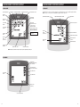
1
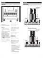
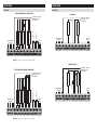
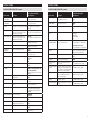
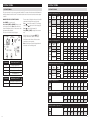
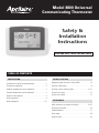
Model 8800 Universal
Communicating Thermostat
Safety &
Installation
Instructions
READ AND SAVE THESE INSTRUCTIONS
Table of contents
Installation
Setup & Testing
Installation location recommendations . . . . . . . . . . . . 2
Equipment type selection switch (SW1) . . . . . . . . . . . 8
Thermostat mounting . . . . . . . . . . . . . . . . . . . . . . . . . . 2
Installer setup menu . . . . . . . . . . . . . . . . . . . . . . . . . . . 8
Outdoor temperature sensor (optional) . . . . . . . . . . . . 2
Installer system settings table . . . . . . . . . . . . . . . . . 9-11
Remote temperature sensor (optional) . . . . . . . . . . . . . 3
System test menu . . . . . . . . . . . . . . . . . . . . . . . . . . . . 12
Power & reset options . . . . . . . . . . . . . . . . . . . . . . . . . 3
System test tables . . . . . . . . . . . . . . . . . . . . . . . . . . . 13
Wiring terminal . . . . . . . . . . . . . . . . . . . . . . . . . . . . . . . 4
Wiring diagrams . . . . . . . . . . . . . . . . . . . . . . . . . . . . . 5-7
References
Quick reference to controls & display . . . . . . . . . . 14-15
Thermostat features . . . . . . . . . . . . . . . . . . . . . . . . . . 16
Troubleshooting . . . . . . . . . . . . . . . . . . . . . . . . . . . . . . 17
Error codes . . . . . . . . . . . . . . . . . . . . . . . . . . . . . . . . . 18
Specifications . . . . . . . . . . . . . . . . . . . . . . . . . . . . . . . 19
Installation
Installation
Installation location recommendations
Remote temperature sensor (optional)
Thermostat should be mounted:
Do not mount thermostat:
• On an interior wall, in a frequently occupied space.
• Behind doors, in corners or other dead air spaces.
• Approximately 5‘ above floor.
• At least 18” from outside wall.
• In direct sunlight, near lighting fixtures, or other
appliances that give off heat.
• Thermostat can be mounted to a vertical junction box.
• On an outside or unconditioned area wall.
• In the flow of a supply register, in stairwells, or near
outside doors.
• On a wall with concealed pipes or ductwork.
A remote temperature sensor can be used if the thermostat is to be mounted in a concealed location. A 8051 flush
mount or 8053 surface mount remote temperature sensor can be attached to the T1 and T2 terminals and mounted
in a recommended area. The remote sensor must be enabled in the installer set-up menu, and once enabled will
override the thermostat’s internal temperature sensor.
Remote temperature sensor should be mounted:
Do not mount remote sensor:
• On an interior wall, in a frequently occupied space.
• Behind doors, in corners or other dead air spaces.
• Approximately 5‘ above floor.
• At least 18” from outside wall.
• In direct sunlight, near lighting fixtures, or other
appliances that give off heat.
• Using less than 300’ of wire.
• On an outside or unconditioned area wall.
• In the flow of a supply register, in stairwells, or near
outside doors.
Thermostat mounting
1. Remove the rear mounting plate from the thermostat.
• On a wall with concealed pipes or ductwork.
2. Pull wires through the opening on the back of the
thermostat.
• Near 120 VAC lines.
3. Position and level the mounting plate of the thermostat
on wall and mark the hole locations with a pencil.
4. Drill 1/4” holes and insert supplied anchors
(drywall only).
5. Place mounting plate over anchors, insert and tighten
screws.
6. Seal wire entry holes to prevent drafts affecting
temperature readings.
B+ A+ B- A- C B O Y Y2 G RC RH W2 W R S2 S1 T1 T2 RSB RSA
Outdoor temperature sensor (optional)
Outdoor temperature can be measured by attaching an 8052 sensor to the S1 and S2 terminals. The outdoor sensor
must be enabled in the installer setup menu.
In heat pump mode the outdoor temperature
sensor can be used to efficiently utilize an air
source heat pump:
Outdoor temperature sensor should be mounted:
• When the outdoor temperature is less than the Low
Balance Point, the heat pump will be locked out and
only auxiliary heating will be used.
• Above snow line.
• When the outdoor temperature is higher than the
High Balance Point, the auxiliary heating will be
locked out and only the heat pump will be used to
provide heating.
• On side of building out of direct sunlight (north side
recommended).
Power & Reset options
The thermostat is a 24VAC powered device with a battery back-up for the clock.
The thermostat has a memory backup that saves the thermostat settings in case of a power interruption. The system
settings will be retained but the clock will reset after 90 seconds with no battery or AC power.
The reset button located under the battery cover can be used to reset the thermostat to factory defaults. The system
settings will also be reset to default.
• At least 3’ away from exhaust vents and condensing
lines.
• Using less than 300’ of wire.
• Do not route wires along 120 VAC lines.
B+ A+ B- A- C B O Y Y2 G RC RH W2 W R S2 S1 T1 T2 RSB RSA
2
3
Installation
Installation
Wiring terminal
CONVENTIONAL HEAT/COOL
Single transformer (use Jumper wire)
Installation notes:
C – 24VAC Thermostat power (common) from 8819
• Ensure power at the HVAC equipment is off.
R – 24VAC Thermostat power (hot) from 8819
• Loosen screw terminals, insert stripped wire and
re-tighten.
B – Reversing valve for heat 2
• Push the excess wire back into the opening and plug
the wall opening to prevent drafts.
Y – 1st stage cooling / compressor or dehumidifier 3
JUMPER
REMOTE TEMP
SENSOR
OUTDOOR TEMP
SENSOR
1st HEATING
FAN
1st COOLING
NOT USED
Two transformers (Remove Jumper Wire)
THERMOSTAT IS POWERED
FROM 8819 OR 24VAC
TRANSFORMER
RC – 24VAC supply cooling4
W2 – 2nd stage heat / auxiliary / E-Heat
W – 1st stage heat / auxiliary / E-Heat / humidifier 3
S1 & S2 – outdoor temperature sensor (optional)
T1 & T2 – remote temperature sensor (optional)
RSA & RSB – 8081 or 8082 Support Module
communication (half duplex)5
1
R efer to Aprilaire HVAC Automation System Installation Manual
for communication wiring details.
2
and B terminals are both de-energized when system mode is
O
OFF or in AUTO when the heating and cooling equipment is idle.
3
When the unit is configured for humidistat mode.
4
J umper between RC & RH is used in single transformer systems
(see wiring diagrams).
COMMUNICATION
TERMINALS
FAN
1st COOLING
RH – 24VAC supply heating4
1st HEATING
COOLING
TRANSFORMER
G – Fan
2nd HEATING
Y2 – 2nd stage cooling / compressor
HEATING
TRANSFORMER
O – Reversing valve for cool2
2nd COOLING
Note: If the HVAC system was installed before the
automation system, the HVAC installer may have
powered the thermostat connecting a wire to the
C terminal and installing a jumper wire from the R
terminal to RH or RC. When used with an automation
system, the R and C terminals on the Model 8800
thermostat should only be connected to the same
terminals on the 8819 or a dedicated 24VAC transformer.
There should be no connection to the R or C terminals
coming from the HVAC equipment.
B+ A+ B- A- C B O Y Y2 G RC RH W2 W R S2 S1 T1 T2 RSB RSA
REMOTE TEMP
SENSOR
A+ / A- – Transmit communication terminal
(reference automation system)1
OUTDOOR TEMP
SENSOR
CAT-5 or equivalent for communication terminals
NOT USED
18-24 gauge thermostat wire
SUPPORT
MODULE
B+ / B- – Receive communication terminal
(reference automation system)1
NOT USED
Wire specifications:
NOT USED
COMMUNICATION
TERMINALS
2nd COOLING
B+ A+ B- A- C B O Y Y2 G RC RH W2 W R S2 S1 T1 T2 RSB RSA
2nd HEATING
TRANSFORMER
THERMOSTAT IS POWERED
FROM 8819 OR 24VAC
TRANSFORMER
SUPPORT
MODULE
B+ A+ B- A- C B O Y Y2 G RC RH W2 W R S2 S1 T1 T2 RSB RSA
Refer to Support Module literature for wiring details.
5
4
5
Installation
Installation
HEAT PUMP
HUMIDISTAT
Single transformer (use Jumper wire)
DRY CONTACT
THERMOSTAT IS POWERED
FROM 8819 OR 24VAC
TRANSFORMER
SUPPORT
MODULE
HUMIDIFIER
DEHUMIDIFIER
REMOTE TEMP
SENSOR
OUTDOOR TEMP
SENSOR
1st AUX HEATING
2nd AUX HEATING
HEAT PUMP
TRANSFORMER
JUMPER
FAN
1st COMPRESSOR
COMMUNICATION
TERMINALS
2nd COMPRESSOR
REVERSING VALVE
THERMOSTAT IS POWERED
FROM 8819 OR 24VAC
TRANSFORMER
COMMUNICATION
TERMINALS
SUPPORT
MODULE
OR
B+ A+ B- A- C B O Y Y2 G RC RH W2 W R S2 S1 T1 T2 RSB RSA
B+ A+ B- A- C B O Y Y2 G RC RH W2 W R S2 S1 T1 T2 RSB RSA
NOTE: “O” is active in cooling and “B” is active in heating.
POWERED CONTACT
THERMOSTAT IS POWERED
FROM 8819 OR 24VAC
TRANSFORMER
SUPPORT
MODULE
HUMIDIFIER
TRANSFORMER
DEHUMIDIFIER
TRANSFORMER
COMMUNICATION
TERMINALS
REMOTE TEMP
SENSOR
OUTDOOR TEMP
SENSOR
1st AUX HEATING
2nd AUX HEATING
HEAT PUMP
TRANSFORMER
FAN
1st COMPRESSOR
2nd COMPRESSOR
COMMUNICATION
TERMINALS
REVERSING VALVE
HEATING
TRANSFORMER
DEHUMIDIFIER
THERMOSTAT IS POWERED
FROM 8819 OR 24VAC
TRANSFORMER
HUMIDIFIER
Two transformers (Remove Jumper Wire)
SUPPORT
MODULE
B+ A+ B- A- C B O Y Y2 G RC RH W2 W R S2 S1 T1 T2 RSB RSA
OR
B+ A+ B- A- C B O Y Y2 G RC RH W2 W R S2 S1 T1 T2 RSB RSA
NOTE: “O” is active in cooling and “B” is active in heating.
6
7
Setup & Testing
Setup & Testing
EQUIPMENT TYPE SELECTION SWITCH (SW1)
INSTALLER SYSTEM SETTINGS TABLE
This thermostat has the option of being used in heat
pump or heat/cool systems. Switch SW1 located on the
back of the thermostat’s face is used to select this option.
This setting can also be checked in the Installer System
Settings under Equipment Type.
SW1
HEAT/COOL
HEAT PUMP
HC
HP
The following table is the list of the settings and their details. Default settings are shown in bold. Some settings are
only available to thermostats set to heat pump or humidistat mode.
Description
00.NETWORK ADDRESS
Network communication address.
1
Address selection of 1 to 64 in steps of 1
01.NUMBER OF NODES
Total number of thermostats on the network.
64
Selection of 1 to 64 in steps of 1
02.BAUD RATE
Communication baud rate.
9600
19200
03.CONTROLLER TYPE
Sets controller to Thermostat or Humidistat.
THERMOSTAT
HUMIDISTAT
Press [NEXT] or [BACK] to page through the settings.
04.EQUIPMENT TYPE
Equipment type is set by SW1.
Press [MENU] to enter main menu.
Press
HEAT/COOL
HEAT PUMP
Press and hold [SETUP] for seven seconds, [INSTALL
SETUP] appears.
Press [DONE] to save and exit, or [CANCEL] to exit
without saving.
05.CONTROL SETUP
Used to lockout heating or cooling outputs
(only available in Heat/Cool mode).
HEAT AND COOL
HEAT ONLY
COOL ONLY
Press [INSTALL SETUP] to enter installer setup menu.
The thermostat will discard changes and exit if nothing
is pressed within 60 seconds.
06.AUTO CHANGEOVER
Enable or disable Auto changeover mode.
DISABLE
ENABLE
07.NUMBER OF STAGES
Number of stages of equipment.
SINGLE
MULTI
08.AUX HEAT STAGES
Number of stages of auxiliary heat equipment.
ONE
TWO
09.Heat/Cool: FAN
CONTROL IN HEATING
Heat Pump: AUXILIARY
EQUIPMENT TYPE
Heat/Cool: Determines if the thermostat or
equipment controls the fan in heating.
Heat Pump: Auxiliary Equipment type.1
GAS/OIL HEAT (equipment controls fan)
ELECTRIC HEAT (thermostat controls fan)
10.Thermostat:
COMPRESSOR MIN OFF
TIME
10.Humidistat:
DEHUMIDIFIER MIN
ON/OFF TIME
Thermostat: Minimum off time for compressor
protection.
Humidistat: Minimum on/off time for dehumidifier
protection.
5 MINUTES
1 to 5 MINUTES
11.Thermostat: HEATING
MIN OFF TIME
11.Humidistat: HUMIDIFIER
MIN ON/OFF TIME
Thermostat: Minimum off time for heating.
Humidistat: Minimum on/off time for humidifier.
2 MINUTES
1 to 5 MINUTES
12.EQUIPMENT MIN ON
TIME
Minimum on time for heating and cooling.
2 MINUTES
1 to 5 MINUTES
13.AUTO CHANGEOVER
TIME
Minimum time between heating and cooling calls.
4 MINUTES
1 to 5 MINUTES
14.REMOTE SENSOR
Select if remote sensor is attached at T1 and T2.
NO
YES
15.OUTDOOR SENSOR
Select if outdoor sensor is attached at S1 and S2.
NO
YES
16.CONTROL SENSOR
BACKUP
Control sensor failure response.
STOP CONTROL (enter Error Mode)
USE BUILT-IN
17.FIRST STAGE
DIFFERENTIAL
1st stage differential.
1°F (0.5°C)
1°F to 9°F (0.5°C to 4.5°C)
18.SECOND STAGE
DIFFERENTIAL
2nd stage differential.
1°F (0.5°C)
1°F to 9°F (0.5°C to 4.5°C)
Note: Thermostat reboots within 10 seconds after switch
position is changed.
HC
HP
Installer setup menu
How to enter the installer setup menu to change system settings:
Press [MODE] to set system to OFF.
SETTING
DESCRIPTION
SETTING
OPTIONS
SETTING
NUMBER
or
to adjust the setting.
To reset the installer settings to the default, reset the
thermostat by pressing the [RESET] button inside the
battery cover.
1
8
Factory default setting (bold)
and setting range
System setting
If utilizing a fossil fuel auxiliary heat system, set to Gas or Oil Furnace. In this setting, the heat pump will lock out before the fossil fuel auxiliary
heat comes on; eliminating the need for a dual fuel kit. If utilizing electric auxiliary heat, set to Electric. In this setting, the heat pump and
electric auxiliary heat are allowed to run simultaneously.
9
10
Setup & Testing
Setup & Testing
INSTALLER SYSTEM SETTINGS TABLE (continued)
INSTALLER SYSTEM SETTINGS TABLE (continued)
Factory default setting (bold)
and setting range
Factory default setting (bold)
and setting range
System setting
Description
41.LOCKOUT TYPE
Screen lockout level. (Override lockout by
holding [MENU] for 7 seconds).
OFF
PARTIAL
FULL
42.MODE LOCKOUT
System mode lockout setting.
DISABLE
ENABLE
43.FAN LOCKOUT
Fan Mode lockout setting.
OFF
TIMED
FULL
44.SETPOINT LOCKOUT
TYPE
Setpoint lockout setting.
OFF
TIME-LIMITED
RANGE-LIMITED
TIME AND RANGE
FULL
45.MAX SETPOINT
CHANGE IN LOCKOUT
Select setpoint limits (only available when
lockout is set to partial lockout).
+/-5 DEGREES (from current setpoint)
±1° to 20° OFF indicates no setpoint changes
or
+/-5% RH (from current setpoint)
±1% to 20% OFF indicates no setpoint changes
DISABLE
ENABLE
46.TEMPORARY CHANGE
PERIOD
Time-limited lockout temporary change period.
Auto changeover mode dead band.
3°F (2°C)
2°F to 9°F (1°C to 5°C)
60 MINUTES
Selection of 0 to 255 minutes in 5 minute step;
0 indicates no temporary change period.
47.NETWORK OVERRIDE
Network override feature setting.
Sets humidity control mode.
HUMIDIFY
DEHUMIDIFY
AUTO
OFF
ENABLE
DISABLE
48.DISPLAY REMOTE
SENSORS
Enable or disable display of support module
monitor (remote) sensor readings.
ENABLE
DISABLE
49.AIR FILTER ALARM
PERIOD
The period for displaying the “Change Air
Filter” message.
OFF
1, 3, 6, 12 MONTHS or “OFF” to disable
50.WATER PANEL ALARM
PERIOD
Set number of months until the first reminder
is required. The following reminders will occur
every 12 months for a flow through humidifier,
and 3/9 months for a drainless humidifier.
OFF
1 to 12 MONTHS or “OFF” to disable
51.HUMIDIFIER TYPE
Select humidifier type. Flow through type
gives a 12 month reminder, and drainless
gives a 3/9 month reminder.
FLOW THROUGH (1 reminder per season)
DRAINLESS (2 reminders per season)
52.DEHUMIDIFIER ALARM
PERIOD
The period for displaying the “Service
Dehumidifier” message.
OFF
1 to 12 MONTHS or “OFF” to disable
53.HVAC ALARM PERIOD
The period for displaying the “Service HVAC”
message.
OFF
1 to 12 MONTHS or “OFF” to disable
System setting
Description
19.THIRD STAGE
DIFFERENTIAL
3rd stage differential.
1°F (0.5°C)
1°F to 9°F (0.5°C to 4.5°C)
20.FOURTH STAGE
DIFFERENTIAL
4th stage differential.
1°F (0.5°C)
1°F to 9°F (0.5°C to 4.5°C)
21.INTEGRAL FACTOR
PERIOD
Short period = more cycles per hour (comfort)
Long period = less cycles per hour (economical).
2 MINUTES
1 to 5 minutes or “OFF” for proportional
control only
22.LOW BALANCE POINT
Outdoor temperature low balance point
(This option is only displayed if the outdoor
temperature sensor is enabled).
20°F (–6°C)
10°F to 50°F (-12°C to 9°C) or OFF to ignore
23.HIGH BALANCE POINT
Outdoor temperature high balance point
(This option is only displayed if the outdoor
temperature sensor is enabled).
65°F (18°C)
40°F to 85°F (3°C to 30°C) or OFF to ignore
24.EXTENDED FAN – HEAT
Extends fan operation after heat call ends.
DISABLE
ENABLE (90 second extension)
25.EXTENDED FAN – COOL
Extends fan operation after cool call ends.
DISABLE
ENABLE (90 second extension)
26.PROGRESSIVE
RECOVERY
Enable or disable Progressive recovery.
27.DEADBAND
28.HUMIDISTAT MODE
29.TEMPERATURE SCALE
Set the thermostat to Fahrenheit or Celsius
mode.
FAHRENHEIT
CELSIUS
30.AUTO DAYLIGHT
SAVINGS
Enable or disable auto daylight savings.
OFF
MARCH (second Sunday in March to the
first Sunday in November)
APRIL (first Sunday in April to the last Sunday
in October)
32.CONSTANT BACKLIGHT
Enable constant, low intensity, backlight when
24VAC is present.
DISABLE
ENABLE
33.BACKLIGHT INTENSITY
Backlight intensity as a percentage of full on.
100 PERCENT
0 – 100%
34.SENSOR OFFSET
Field adjustment of the controlling temperature
sensor.
0°: No offset applied
–8°F to +8°F (-4°C to +4°C)
35.PROGRAM FORMAT
Select weekly program format.
7-DAY (Mon, Tue, Wed, Thu, Fri, Sat, Sun)
5/1/1 (weekdays, Saturday and Sunday)
5/2 WEEKDAYS (weekdays and weekends)
NON-PROG
36.EVENT CONFIGURATION
Setting for event naming.
RESIDENTIAL
COMMERCIAL
37.EVENTS PER DAY
Number of program events per day.
FOUR
TWO
38.USER SECURITY SETUP
Enable or disable security setup system
variables in the User Setup Screens.
DISABLE
ENABLE
39.SECURITY
Enable or disable security.
DISABLE
ENABLE
40.SECURITY PIN
Security pin code.
####
4-digit numeric pin
11
Setup & Testing
Setup & Testing
System test menu
SYSTEM TEST TABLES
The system test menu is used to test a system after installation. The outputs of the thermostat or humidistat can be
manually activated to test their function. The instructions below show how to enter the test mode and turn outputs
on and off.
How to enter the system test menu:
Press [MODE] to set system to off.
Press and hold [FAN] and [MODE] for three seconds
to enter system test mode. Note: Buttons will not be
shown in humidistat mode. Press in the same area that
the button would be displayed.
The screen of the first test step is displayed:
TEST NUMBER
MODEL
(SW1 SETTING)
FLASHES
IF 24VAC
IS NOT
PRESENT
The test number is displayed on the upper left, and the
output state is displayed in the message center.
Press
to turn on the output (01). For multi stage
output, press
again to turn on the 2nd stage (02).
Press
STAGE
Test Number
Thermostat System Test
60
Heating equipment test
61
Cooling equipment test
62
Auxiliary equipment test (HP only)
63
Fan equipment test
Test Number
Humidistat System Test
70
Humidification equipment test
71
Dehumidification equipment test
Button
Press
Equipment
Type
1st UP
press
Heat Cool
Press [BACK] or [NEXT] to change to the next test
step.
2nd UP
press
When the last step is done, press [NEXT]. The
message “installer test complete“ will display.
All minimum on and off timers will be reset after
returning from system test mode.
Stages
Heat
Type
W
Gas
ON
Electric
ON
W2
Y
Y2
G
O
B
ON
Heat Pump
ON
ON
ON
ON
ON
1
to turn off all the outputs (00).
Note: Second stage will only be displayed when the
thermostat is set to multi-stage mode.
OUTPUT
STATE
Test 60: Heating Equipment Test
Heat Cool
Heat Pump
2
Gas
ON
ON
Electric
ON
ON
ON
ON
ON
ON
1
2
ON
ON
ON
Y
Y2
G
Test 61: Cooling Equipment Test
Button
Press
Equipment
Type
1st UP
press
Heat Cool
ON
ON
ON
Heat Pump
ON
ON
ON
2nd UP
press
Heat Cool
Heat Pump
Stages
W
W2
O
B
1
2
ON
ON
ON
ON
ON
ON
ON
ON
Y
Y2
G
O
1
2
Test 62: Auxiliary Equipment Test (HP only)
Button
Press
Equipment
Type
1st UP
press
Heat Pump
2nd UP
press
Heat Pump
Heat
Type
W
W2
Gas
ON
Electric
ON
Gas
ON
ON
Electric
ON
ON
W
W2
B
ON
ON
ON
ON
ON
ON
Test 63: Fan Equipment Test
Button
Press
Y
Y2
1st UP
press
G
O
B
O
B
ON
Test 70: Humidifier Equipment Test
Button
Press
W
1st UP
press
ON
W2
Y
Y2
G
ON
ON
Test 71: Dehumidifier Equipment Test
Button
Press
1st UP
press
12
W
W2
Y
ON
Y2
G
O
ON
ON
B
13
Quick Reference to controls & Display
Quick Reference to controls & Display
Home Screen
HUMIDISTAT
ROOM TEMPERATURE
Current DAY
OUTDOOR TEMPERATURE
ROOM RELATIVE HUMIDITY
TEMPERATURE SETTING
FAN MODE
BUTTON
Temperature
ADJUSTMENT
FAN MODE
SETTING
ROOM RELATIVE HUMIDITY
ROOM RELATIVE HUMIDITY SETPOINT
Current DAY
HUMIDIFIER ADJUSTMENT
HOLD BUTTON
SYSTEM MODE
BUTTON
(IN PROGRAMMABLE MODE
SETS OR CLEARS HOLD)
NETWORK OVERRIDE
SYSTEM MODE
SETTING
(IN NON-PROGRAMMABLE MODE)
Heat pump mode only
Emergency/AUXILIARY
heat (RED)
EQUIPMENT
STATUS
MESSAGE
CENTER
(SCROLLING TEXT)
CURRENT TIME
& DATE
(SCROLLING TEXT)
CURRENT TIME & DATE
OUTDOOR TEMPERATURE
DEHUMIDIFIER ADJUSTMENT
Indicator shows through housing
MESSAGE
CENTER
LOW BATTERY
INDICATOR
The Model 8800 has the option of being configured as a humidistat that can control a humidifier and dehumidifier.
Note: The 8800 is set to operate as a humidistat through the installer setup menu.
NETWORK OVERRIDE
(IF ENABLED)
MAIN MENU BUTTON
MAIN MENU BUTTON
Note: Backlight is activated with first button press and automatically turns off.
MAIN MENU
CLEAN SCREEN
(LOCKOUT TOUCH SCREEN
FOR 30 SECONDS)
SET VACATION HOLD
(HOLD–TO TIME AND DATE)
SET CURRENT TIME
SET SCHEDULE
BUTTON
SET CURRENT DATE
DONE BUTTON
(EXIT MENU)
USER SYSTEM SETTINGS
14
15
Thermostat Features
• Large touch screen with adjustable backlight.
• Message center provides feedback and instructions.
• 7 day programmability or separately programmable
weekday/weekend schedules.
• Thermostat can be removed from the wall for easy
programming (batteries must be installed).
• Front battery door access for fast, easy replacement.
• Displays room temperature, room humidity,
temperature setting, and optional outdoor temperature.
• Air filter, humidifier, dehumidifier, and HVAC service
indicators.
• Programmable fan control with fan circulation mode.
Troubleshooting
• Easy to use temperature control can override program
schedule at any time.
• Progressive recovery ensures proper temperature at
the start of a program event.
• Built in compressor protection prevents damage to
your equipment.
Display is blank
• Check circuit breaker and reset if necessary.
• Make sure power switch at heating & cooling
system is on.
• RS485 communications ready.
• Universal system compatibility.
• Configurable to control a humidifier or dehumidifier.
Temperature settings do not change
Make sure heating and cooling temperatures are set to
acceptable ranges:
Heat pump issues cool air in heat mode,
or warm air in cool mode
• Check wiring at the terminal block to confirm the
reversing valve is connected to the proper terminal.
O is active in cooling and B is active in heating.
• Heat: 40° to 90°F (4° to 32°C).
• Cool: 50° to 99°F (10° to 37°C).
Heating system does not respond
(“HEATING” appears on screen)
• Check for 24VAC at the equipment on the secondary
side of the transformer between power and
common. If voltage is not present, check the heating
equipment to find the cause of the problem.
• Check for 24VAC between the heat terminal (W)
and the transformer common. If 24VAC is present,
the thermostat is functional. Check the heating
equipment to find the cause of the problem.
• Check for loose or broken wires between the
thermostat and the heating equipment.
Cooling system does not respond
(“COOLING” appears on screen)
• Check for 24VAC at the equipment on the secondary
side of the transformer between power and
common. If voltage is not present, check the cooling
equipment to find the cause of the problem
• Check for 24VAC between the cooling terminal (Y)
and the transformer common. If 24VAC is present,
the thermostat is functional. Check the cooling
system to find the cause of the problem.
• Check for loose or broken wires between the
thermostat and the cooling equipment.
16
• Check System Setting 09 (Fan Control), to make sure
the fan control is properly set to match the type of
system (see page 9).
• Make sure furnace door is closed securely.
• Battery back-up.
• System test mode.
Fan does not turn on in a call for heat
Heat/cool both on at same time
• Check SW1 (Equipment Type), to make sure it is set
to match the installed heating/cooling equipment
(see page 8).
• Check to make sure heating and cooling wires are
not shorted together.
Heating equipment is running in
cool mode
• Check SW1 (Equipment Type), to make sure it is set
to match the installed heating/cooling equipment
(see page 8).
“HEATING” is not displayed
• Check Installer System Setting number 05
(Control Setup) is set correctly.
• Change the System Mode to Heat, and set
the temperature level above the current room
temperature.
“COOLING” is not displayed
• Check Installer System Setting number 05
(Control Setup) is set correctly.
• Change the System Mode to Cool, and set
the temperature level below the current room
temperature.
17
Error Codes
Specifications
If the thermostat enters an error mode, all outputs are turned off. The thermostat attempts to recover every 10 minutes.
If the error does not clear, use the reset button. This will return all settings back to factory default.
Error code
01
02
Message
“SENSOR ERROR”
Error Description
Open temperature sensor circuit
Temperature
Relative humidity
Operating: 5% to 90% R.H. (non-condensing)
Shorted temperature sensor circuit
03
“RH SENSOR ERROR”
Invalid response from the RH sensor
04
“EEPROM ERROR”
Error in permanent memory
“SENSOR ERROR”
All controlling support modules are unresponsive and
the built-in sensor is not used as a backup option
05
Environment
Operating: 32° to 120°F (0° to 48.9°C)
Shipping: -30° to 150°F (-34.4° to 65.5°C)
Electrical
Operating voltage
24VAC (18 – 30VAC)
Current
Maximum: 2.5A (total), 1.0A (single output)
Maximum surge current: 5A
Battery back-up
AA size alkaline battery x 2
Outdoor & Remote temperature sensor
Maximum distance: 300 feet
Room temperature measurement
Display range: 32° to 99°F (0° to 40°C)
Outdoor temperature measurement
Display range: -20° to 130°F (-30° to 55°C)
Setpoint temperature range
Heat: 40° to 90°F (4° to 32°C)
Cool: 50° to 99°F (10° to 37°C)
Setpoint humidity range
Humidification: 10% to 90% R.H.
Dehumidification: 10% to 90% R.H.
Thermal
18
19
P.O. Box 1467 • Madison, WI 53701-1467 • Phone: 800/334-6011 • Fax: 608/257-4357
www.aprilairepartners.com
61000761 1.12
B2205382C
© 2012 Aprilaire – A division of Research Products Corporation