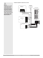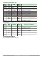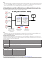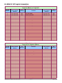
1
EZ-ZONE® RUI/Gateway User’s Manual EZ-ZONE RM EZ-ZONE ST RUI/Gateway TOTAL CUSTOMER SATISFACTION 3 Year Warranty ISO 9001 1241 Bundy Boulevard., Winona, Minnesota USA 55987 Phone: +1 (507) 454-5300, Fax: +1 (507) 452-4507 http://www.watlow.com 0600-0060-0000 Rev. B February 2010 Registered Company Winona, Minnesota USA Made in the U.S.A. Safety Information Unit is compliant with European Union directives. See Declaration of Conformity for further details on Directives and Standards used for Compliance. We use note, caution and warning symbols throughout this book to draw your attention to important operational and safety information. A “NOTE” marks a short message to alert you to an important detail. Unit has been reviewed and approved by CSA International for use as Temperature IndicatingRegulating Equipment per CSA C22.2 No. 24 or C22.2 #14. See: www.csa-international.org A “CAUTION” safety alert appears with information that is important for protecting your equipment and performance. Be especially careful to read and follow all cautions that apply to your application. Unit has been reviewed and approved by ODVA for compliance with DeviceNet communications protocol. See: www.odva.org A “WARNING” safety alert appears with information that is important for protecting you, others and equipment from damage. Pay very close attention to all warnings that apply to your application. The electrical hazard symbol, Ó (a lightning bolt in a triangle) precedes an electric shock hazard CAUTION or WARNING safety statement. Symbol Explanation CAUTION – Warning or Hazard that needs further explanation than label on unit can provide. Consult users manual for further information. ESD Sensitive product, use proper grounding and handling techniques when installing or servicing product. Unit protected by double/reinforced insulation for shock hazard prevention. Do not throw in trash, use proper recycling techniques or consult manufacturer for proper disposal. Enclosure made of Polycarbonate material. Use proper recycling techniques or consult manufacturer for proper disposal. Unit can be powered with either alternating current (ac) voltage or direct current (dc) voltage. Unit is a Listed device per Underwriters Laboratories®. It has been evaluated to United States and Canadian requirements for Process Control Equipment. UL 61010 and CSA C22.2 No. 61010. File E185611 QUYX, QUYX7. See: www.ul.com Unit is a Listed device per Underwriters Laboratories®. It has been evaluated to United States and Canadian requirements for industrial control equipment UL 508 CSA C22.2 #14 File E102269 NKCR, NKCR7. See: www.ul.com Unit has been reviewed and approved by ODVA for compliance with Ethernet/IP communications protocol. See: www.odva.org Warranty The EZ-ZONE® RUI/Gateway is manufactured by ISO 9001-registered processes and is backed by a three-year warranty to the first purchaser for use, providing that the units have not been misapplied. Since Watlow has no control over their use, and sometimes misuse, we cannot guarantee against failure. Watlow’s obligations hereunder, at Watlow’s option, are limited to replacement, repair or refund of purchase price, and parts which upon examination prove to be defective within the warranty period specified. This warranty does not apply to damage resulting from transportation, alteration, misuse or abuse. The purchaser must use Watlow parts to maintain all listed ratings. Technical Assistance If you encounter a problem with your Watlow controller, review your configuration information to verify that your selections are consistent with your application: inputs, outputs, alarms, limits, etc. If the problem persists, you can get technical assistance from your local Watlow representative (see back cover), by e-mailing your questions to wintechsupport@watlow. com or by dialing +1 (507) 494-5656 between 7 a.m. and 5 p.m., Central Standard Time (CST). Ask for for an Applications Engineer. Please have the following information available when calling: • Complete model number Return Material Authorization (RMA) 1. Call Watlow Customer Service, (507) 454-5300, for a Return Material Authorization (RMA) number before returning any item for repair. If you do not know why the product failed, contact an Application Engineer or Product Manager. All RMA’s require: • Ship-to address • Bill-to address • Contact name • Phone number • Method of return shipment • Your P.O. number • Detailed description of the problem • Any special instructions • Name and phone number of person returning the product. 2. Prior approval and an RMA number from the Customer Service Department is required when returning any product for credit, repair or evaluation. Make sure the RMA number is on the outside of the carton and on all paperwork returned. Ship on a Freight Prepaid basis. 3. After we receive your return, we will examine it and try to verify the reason for returning it. 4. In cases of manufacturing defect, we will enter a repair order, replacement order or issue credit for material returned. In cases of customer mis-use, we will provide repair costs and request a purchase order to proceed with the repair work. 5. To return products that are not defective, goods must be be in new condition, in the original boxes and they must be returned within 120 days of receipt. A 20 percent restocking charge is applied for all returned stock controls and accessories. 6. If the unit is unrepairable, you will receive a letter of explanation. and be given the option to have the unit returned to you at your expense or to have us scrap the unit. 7. Watlow reserves the right to charge for no trouble found (NTF) returns. The EZ-ZONE® Remote User's Interface User’s Manual is copyrighted by Watlow Winona, Inc., © February 2010 with all rights reserved. TC Table of Contents Chapter 1: Overview . . . . . . . . . . . . . . . . . . . . . . . . . . . . . . . . . . . . . 3 Features and Benefits. . . . . . . . . . . . . . . . . . . . . . . . . . . . . . . . . . . . . . . . 3 RUI/GTW Panel Cutout Dimensions. . . . . . . . . . . . . . . . . . . . . . . . . . . . . 4 Chapter 2: Install, Wire and Set Address . . . . . . . . . . . . . . . . . . . . . . . 4 Mounting the Remote User Interface (RUI). . . . . . . . . . . . . . . . . . . . . . . 5 Standard Bus EIA-485 Communications . . . . . . . . . . . . . . . . . . . . . . . . . 6 EIA-232/485 Modbus RTU Communications. . . . . . . . . . . . . . . . . . . . . . 6 EtherNet/IP™ and Modbus TCP Communications . . . . . . . . . . . . . . . . . . 7 DeviceNet™ Communications. . . . . . . . . . . . . . . . . . . . . . . . . . . . . . . . . . 7 Profibus DP Communications . . . . . . . . . . . . . . . . . . . . . . . . . . . . . . . . . 7 Wiring a Serial EIA-485 Network . . . . . . . . . . . . . . . . . . . . . . . . . . . . . . . 8 Responding to a Displayed Message. . . . . . . . . . . . . . . . . . . . . . . . . . . 10 Chapter 3: Keys and Displays . . . . . . . . . . . . . . . . . . . . . . . . . . . . . 10 Programming the EZ Key Using an RUI. . . . . . . . . . . . . . . . . . . . . . . . . 13 Using the RUI with PM Family Controllers. . . . . . . . . . . . . . . . . . . . . . . 13 Using the RUI with RM Family Controllers. . . . . . . . . . . . . . . . . . . . . . . 13 Default Home Pages. . . . . . . . . . . . . . . . . . . . . . . . . . . . . . . . . . . . . . . . 14 EZ-ZONE PM Express Home Page. . . . . . . . . . . . . . . . . . . . . . . . . . . . . 15 EZ-ZONE ST Home Page . . . . . . . . . . . . . . . . . . . . . . . . . . . . . . . . . . . . 16 EZ-ZONE PM Home Page. . . . . . . . . . . . . . . . . . . . . . . . . . . . . . . . . . . . 17 EZ-ZONE RMC (Controller) Home Page. . . . . . . . . . . . . . . . . . . . . . . . . 18 EZ-ZONE RME (Expansion) Home Page. . . . . . . . . . . . . . . . . . . . . . . . . 18 Chapter 4: RUI Page . . . . . . . . . . . . . . . . . . . . . . . . . . . . . . . . . . . . 19 Communications Menu. . . . . . . . . . . . . . . . . . . . . . . . . . . . . . . . . . . . . . 20 Global Menu. . . . . . . . . . . . . . . . . . . . . . . . . . . . . . . . . . . . . . . . . . . . . . 22 Gateway Menu . . . . . . . . . . . . . . . . . . . . . . . . . . . . . . . . . . . . . . . . . . . . 22 Security Setting Menu . . . . . . . . . . . . . . . . . . . . . . . . . . . . . . . . . . . . . . 23 Unlock Security Setting Menu . . . . . . . . . . . . . . . . . . . . . . . . . . . . . . . . 23 Diagnostics Menu. . . . . . . . . . . . . . . . . . . . . . . . . . . . . . . . . . . . . . . . . . 24 Chapter 5: Using an RUI/Gateway. . . . . . . . . . . . . . . . . . . . . . . . . . . 25 Conceptual View of the RUI/GTW. . . . . . . . . . . . . . . . . . . . . . . . . . . . . . 25 Using Modbus RTU . . . . . . . . . . . . . . . . . . . . . . . . . . . . . . . . . . . . . . . . 25 Wat low EZ-ZONE ® RUI/Gateway • 1 • Table of Contents TC Table of Contents (cont.) CIP - Communications Capabilities . . . . . . . . . . . . . . . . . . . . . . . . . . . . 27 Using DeviceNet™ . . . . . . . . . . . . . . . . . . . . . . . . . . . . . . . . . . . . . . . 27 DeviceNet RUI/GTW LED Indicators. . . . . . . . . . . . . . . . . . . . . . . . . . 28 Using EtherNet/IP™ . . . . . . . . . . . . . . . . . . . . . . . . . . . . . . . . . . . . . . 29 Using Modbus TCP . . . . . . . . . . . . . . . . . . . . . . . . . . . . . . . . . . . . . . . . 29 Ethernet RUI/GTW LED Indicators . . . . . . . . . . . . . . . . . . . . . . . . . . . 31 Using Profibus DP . . . . . . . . . . . . . . . . . . . . . . . . . . . . . . . . . . . . . . . . . 32 Profibus DP RUI/GTW LED Indicators . . . . . . . . . . . . . . . . . . . . . . . . 32 Software Configuration. . . . . . . . . . . . . . . . . . . . . . . . . . . . . . . . . . . . . . 34 Saving Settings to Non-volatile Memory . . . . . . . . . . . . . . . . . . . . . . . . 37 Chapter 6: Appendix . . . . . . . . . . . . . . . . . . . . . . . . . . . . . . . . . . . . 38 Troubleshooting. . . . . . . . . . . . . . . . . . . . . . . . . . . . . . . . . . . . . . . . . . . 38 Modbus - Programmable Memory Blocks. . . . . . . . . . . . . . . . . . . . . . . 39 EZ-ZONE ST CIP Implicit Assemblies. . . . . . . . . . . . . . . . . . . . . . . . . . . 41 EZ-ZONE PM CIP Implicit Assemblies . . . . . . . . . . . . . . . . . . . . . . . . . . 42 EZ-ZONE RMC CIP Implicit Assemblies. . . . . . . . . . . . . . . . . . . . . . . . . 43 Specifications. . . . . . . . . . . . . . . . . . . . . . . . . . . . . . . . . . . . . . . . . . . . . 44 Ordering Information . . . . . . . . . . . . . . . . . . . . . . . . . . . . . . . . . . . . . . . 45 How to Reach Us. . . . . . . . . . . . . . . . . . . . . . . . . . . . . . . . . . . . . . . . . . 47 Wat low EZ-ZONE ® RUI/Gateway • 2 • Table of Contents 1 Chapter 1: Overview Features and Benefits Using the RUI/GTW as a Gateway Remote User Interface/Gateway (RUI/GTW) • Uses one RUI for multiple zones The addition of a gateway card allows information to be passed from the Standard Bus side of the gateway (EZ-ZONE®-family controllers) to one or more of the following popular field bus networks: • Shallow panel depth allows it to fit in small spaces • Eliminates the costs and complexity of having to bring all controller related wires to the front panel • EtherNet/IP™ • DeviceNet™ • Modbus TCP • Modbus RTU • Profibus DP The networks see the gateway and RUI as separate devices. Both sides of the gateway will require unique addresses based on the protocol specifications. • Enables the use of multiple RUIs to improve the system’s usability and flexibility Agency approvals: UL Listed, cULus, CSA, CE, RoHS, • Assures prompt product acceptance RUI/Gateway • Reduces end product documentation costs Short Case • CSA C22.2 #14 Approved File 158031 PCs • cULus UL 508 Listed approval File E102269 • UL® 50 Type 4X, NEMA 4X indoor locations, IP65 front panel seal (indoor use only) PLCs Fieldbus Network Protocol - EtherNet/IP - DeviceNet - Modbus TCP - Modbus RTU - Profibus DP Watlow Standard Bus Network Other Remote User Interfaces EZ-ZONE-family Controllers Long Case • UL® Listed to UL 61010-1 File E185611 • UL® Reviewed to CSA C22.2 No.61010-1-04 Note: Excessive writes through the gateway to other EZZONE® family controllers may cause premature EE-PROM failure. For more detail see the section entitled “Saving Settings to Nonvolatile Memory.” • UL® 50 Type 4X, NEMA 4X indoor locations, IP66 front panel seal (indoor use only) • ODVA-EtherNet/IP™ and DeviceNet Compliance • CSA C22.2 No. 24 File 158031 Class 4813-02 Note: A Standard Bus network can communicate with a maximum of eight RUIs with up to four of those being gateways. Valid Standard Bus addresses for RUIs equipped with the gateway option are 1, 2, 3 or 4. As is always the case each RUI must have a unique Standard Bus address. • Profibus DP P3T Armor Sealing System • NEMA 4X and IP65, indoor use only • Offers water and dust resistance, can be cleaned and washed down Three-year warranty • Demonstrates Watlow’s reliability and product support EZ-Key • Programmable EZ-Key enables simple one-touch operation of repetitive user activities • This is a test to see how a normal bullet is applied to the source document and what formating is appleied. Wat low EZ-ZONE ® RUI/Gateway • 3 • Chapter 1 Over view 2 Chapter 2: Install, Wire and Set Address RUI/GTW Panel Cutout Dimensions 52.07 mm (2.05 in) 76.25 mm (3.00 in) 45.21 mm (1.78 in) (1.77 to 1.79 in) 1.40 mm (0.06 in) 59.10 mm (2.33 in) Panel Cutout 52.07 mm (2.05 in) your panel thickness 1.5 to 9.7 mm (0.06 to 0.38 in) 15.75 mm (0.62 in) 45.21 mm (1.78 in) (1.77 to 1.79 in) 44.70 mm (1.76 in) 9.65 mm (0.38 in) minimum Side View short case (EZK _ - _ A _ _ - _ _ _ _) 10.16 mm (4.00 in) 30.73 mm (1.21 in) 21.59 mm (0.85 in) 12.40 mm (0.49 in) 15.8 mm (0.62 in) 76.26 mm (3.00 in) 101.6 mm (4.00 in) 1.40 mm (0.06 in) 53.3 mm (2.10 in) 53.3 mm (2.10 in) 43.94 mm (1.73 in) Side Side View long case Back View short case 10.16 mm Front Front View (0.4 in) 30.73 mm (1.21 in) E8 51.2 mm (2.02 in) 98 E7 99 E6 CF E5 CD E4 CE E3 E2 E1 Top View long case (EZK_-_(2, 3, 5 or 6)_ _-_ _ _ _) Top Back Back View long case An EtherNet/IP™ and Modbus TCP gateway in slot B. Shown with supplied cable. Wat low EZ-ZONE ® RUI/Gateway • 4 • Chapter 2 Install and Wire Mounting the Remote User Interface (RUI) 1. Make the panel cutout using the mounting template dimensions in this chapter. Insert the case assembly into the panel cutout. 2. While pressing the case assembly firmly against the panel, slide the mounting collar over the back of the RUI. If the installation does not require an IP66/NEMA 4X seal, slide the mounting collar up to the back of the pan- el tight enough to eliminate the spacing between the gas ket and the panel. 3. For an IP66/NEMA 4X seal, place the blade of a screw driver in the notch of the mounting collar assembly and push to ward the panel while applying pressure to the face of the RUI. Don't be afraid to apply enough pressure to properly install the RUI. If you can move the case assembly back and forth in the cutout, you do not have a proper seal. The tabs on each side of the bracket have teeth that latch into the ridges. Each tooth is staggered at a different depth from the front so that only one of the tabs one each side is locked onto the ridges at a time. The seal is good if the distance from the panel and the top half of the assembly is 16 mm (0.630 in.) or less, and the distance bottom half and the panel is 13.3 mm (0.525 in.) or less Wat low EZ-ZONE ® RUI/Gateway • 5 • Chapter 2 Install and Wire Ó Warning: Use National Electric (NEC) or other country-specific standard wiring and safety practices when wiring and connecting this controller to a power source and to electrical sensors or peripheral devices. Failure to do so may result in damage to equipment and property, and/or injury or loss of life. Power Slot C long case 98 99 power power • Minimum/Maximum Ratings fuse • 85 to 264VÅ (ac) Slot C short case CF CD 98 CE 99 B5 CF D6 CD D5 CE • 20.4 to 26.4 Vı (ac/dc) power power fuse • 47 to 63Hz • 6VA maximum B5 Power Power D6 Standard Bus EIA-485 D5 Communications Slot C long case 98 Slot C short case 99 CF common CD CE T-/R- 98 T+/R+ 99 CF common B5 CD D6 CE D5 • Wire T-/R- to the A terminal of the EIA-485 port. • Wire T+/R+ to the B terminal of the EIA-485 port. • Wire common to the common terminal of the EIA-485 port. • Do not route network wires with power wires. Connect network wires in daisy-chain fashion when connecting multiple devices in a network. • Do not connect more than 16 controllers on a network. • maximum network length: 1,200 meters (4,000 feet) • 1/8th unit load on EIA-485 bus T-/RT+/R+ Standard Bus EIA-485 Standard Bus EIA-485 EIA-232/485 Modbus RTU Communications Slot B 485 T+/R+ CB 485 T-/R- CA 485 common CC 485 T+/R+ CB 485 T-/R- CA 232 common C5 232 (TX) to DB9 pin 2 (RD) C3 232 (RD) to DB9 pin 3 (TX) C2 Modbus-IDA Terminal • Wire T-/R- to the A terminal of the EIA-485 port. • Wire T+/R+ to the B terminal of the EIA-485 port. • Wire common to the common terminal of the EIA485 port. • Do not route network wires with power wires. Connect network wires in daisychain fashion when connecting multiple devices in a network. • A termination resistor may be required. Place a 120 Ω resistor across T+/R+ and T-/R- of last controller on network. • Do not wire to both the EIA485 and the EIA-232 pins at the same time. EIA/TIA-485 Name Watlow Terminal Label Function DO A CA or CD T-/R- D1 B CB or CE T+/R+ common common CC or CF common Wat low EZ-ZONE ® RUI/Gateway • 6 • • Two EIA-485 terminals of T/R are provided to assist in daisy-chain wiring. • Do not connect more than one EZ-ZONE® PM controller on an EIA-232 network. • maximum number of EZZONE® PM controllers on a Modbus RTU EIA-485 network: 247 • maximum EIA-232 network length: 15 meters (50 feet) • maximum EIA-485 network length: 1,200 meters (4,000 feet) • 1/8th unit load on EIA-485 bus. EZK _-_ 2 _ _-A _ A A Chapter 2 Install and Wire Ó Warning: Use National Electric (NEC) or other country-specific standard wiring and safety practices when wiring and connecting this controller to a power source and to electrical sensors or peripheral devices. Failure to do so may result in damage to equipment and property, and/or injury or loss of life. EtherNet/IP™ and Modbus TCP Communications Slot B unused E8 RJ-45 pin unused E7 8 receive - T568B wire color brown Signal unused Slot B E8 E6 7 brown & white unused E7 unused E5 6 green receive - E6 unused E4 5 white & blue unused E5 receive + E3 4 blue unused E4 transmit - E2 transmit + E1 3 white & green receive + E3 2 orange transmit - E2 1 white & orange transmit + E1 • Do not route network wires with power wires. • Connect one Ethernet cable per device to a 10/100 mbps Ethernet switch. Both Modbus TCP and EtherNet/IP™ are available on the network. Ethernet IP Note: When changing the fixed IP address cycle module power for new address to take effect. DeviceNet™ Communications Slot B Terminal Signal Function V+ V+ CAN_H V+ V+ DeviceNet™ power CH shield CH CAN_H SH positive side of DeviceNet™ bus CAN_L CL SH shield shield interconnect V- CL CAN_L negative side of DeviceNet™ bus V- V- DeviceNet™ power return V- T2 S2 R2 Devicenet Profibus DP Communications • Wire T-/R- to the A terminal of the EIA485 port. Slot B +5Vdc Voltage Potential VP 485 T+/R+ B 485 T-/R- A Digital ground DG Termination resistor B trB 485 T+/R+ B 485 T-/R- A Termination resistor A • Wire T+/R+ to the B terminal of the EIA485 port. • Wire Digital Ground to the common terminal of the EIA-485 port. trA • Do not route network wires with power wires. Connect network wires in daisychain fashion when connecting multiple devices in a network. a jumper across pins trB and B and trA and A. • If external termination is to be used with a 150 Ω cable place a 390 Ω resistor across pins VP and B, a 220 Ω resistor across pins B and A, and lastly, place a 390 Ω resistor across pins DG and A. • Do not connect more than 32 EZ-ZONE devices on any given segment. • Maximum EIA-485 network length: 1,200 • A termination resistor meters (4,000 feet) should be used if this controller is the last • 1/8th unit load on one on the network. EIA-485 bus. • If using a 150 Ω cable Watlow provides internal termination. Place Wat low EZ-ZONE ® RUI/Gateway • 7 • Chapter 2 Install and Wire Ó Warning: Use National Electric (NEC) or other country-specific standard wiring and safety practices when wiring and connecting this controller to a power source and to electrical sensors or peripheral devices. Failure to do so may result in damage to equipment and property, and/or injury or loss of life. Wiring a Serial EIA-485 Network Note: The RUI without a gateway installed, can communicate using Watlows' Standard Bus only. Do not route network wires with power wires. Connect network wires in daisy-chain fashion when connecting multiple devices in a network. A termination resistor may be required. Place a 120 Ω resistor across T+/R+ and T-/R- of the last controller on a network. Note: Do not route network wires with power wires. An RUI/Gateway allows for connectivity between dissimilar networks. In this case, Ethernet on one side and Standard Bus on the other. Power Supply EZ-ZONE ST Note: Excessive writes through the gateway to other EZ-ZONE family controllers may cause premature EEPROM failure. For more detail see the section entitled “Saving Settings to Non-volatile Memory.” EZ-ZONE RMC RMC _ _ _ _ _ _ _ _ _ A _ _ ST_ _ - _ _ A _ -_ _ _ _ fuse 98 99 CF CD B5 CE D6 D5 T-/R- T+/R+ power power common Standard Bus Network power 98 power 99 EZ-ZONE PM com CF T-/R- CD T+/R+ CE PM _ _ _ _ _ - A _ _ _ _ _ _ Slot C B5 D6 98 CY CZ CX CD CE 99 power power EZ-ZONE RUI/GTW EZK _ - _ 3 _ _ - _ _ _ _ E8 CF 98 D5 common power power E7 99 E6 CF E5 CD T-/R- E4 CE T+/R+ T-/R- common T+/R+ Standard Bus Network E3 E2 E1 Ethernet Switch PC Wat low EZ-ZONE ® RUI/Gateway EtherNet IP and/or Modbus TCP Network PLC HMI • 8 • PLC Chapter 2 Install and Wire Ó A network using Watlow's Standard Bus and an RUI Power Supply EZ-ZONE ST ST_ _ - _ _ A _ -_ _ _ _ fuse EZ-ZONE RMC RMC _ _ _ _ _ _ _ _ _ A _ _ 98 99 CF CD B5 D6 CE D5 T+ / R+ T- / R- Warning: Use National Electric (NEC) or other country-specific standard wiring and safety practices when wiring and connecting this controller to a power source and to electrical sensors or peripheral devices. Failure to do so may result in damage to equipment and property, and/or injury or loss of life. power common 98 EZ-ZONE PM PM _ _ _ _ _ - A _ _ _ _ _ _ 99 CF CD CE power com T- / RT+ / R+ B5 Slot C D6 EZ-ZONE RUI EZK _ - _ A _ _ - _ _ _ _ 98 99 CF CD CE Wat low EZ-ZONE ® RUI/Gateway • 9 • CY CZ CX CE 99 CD CF 98 D5 power common power common T- / RT+ / R+ T- / RT+ / R+ Chapter 2 Install and Wire 3 Chapter 3: Keys and Displays Upper Display: In the Home Page, displays the process value, otherwise displays the value of the parameter in the lower display. Temperature Units: ® Zone Display: Output Activity: Indicates the controller zone that the RUI is currently communicating with. A = zone 10 b = zone 11 C = zone 12 d = zone 13 Number LEDs indicate activity of outputs. A flashing light indicates output activity. E = zone 14 F = zone 15 h = zone 16 J = zone 17 Percent Units: Lights when the controller is displaying values as a percentage or when the open-loop set point is displayed. Lower Display: Indicates the set point or output power value during operation, or the parameter whose value appears in the upper display. Profile Activity; Lights when a profile is running. Flashes when a profile is paused. EZ Key: This key can be programmed to do various tasks, such as starting a profile. Indicates whether the temperature is displayed in Fahrenheit or Celsius. Communications Activity Infinity Key ˆ Advance Key ‰ In the Home Page, press to scroll through the network zones, clears alarms and errors if clearable. Advances through parameter prompts. Responding to a Displayed Message Attention Codes Push the Advance Key ‰ to display Ignore [ignr] in the upper display and the message source, such as Limit High [Li;h1] in the lower display. Use the Up ¿ and Down ¯ keys to scroll through possible responses, such as Clear [`CLr] or Silence [`SiL], then push the Advance ‰ or Infinity ˆ key to execute the action. See the table below for further information on the Attention Codes. An active message will cause the display to toggle between the normal settings and the active message in the upper display and Attention [Attn] in the lower display. Your response will depend on the message and the controller settings. Some messages, such as Ramping and Tuning, indicate that a process is underway. If the message was generated by a latched alarm or limit condition, the message can be cleared when the condition no longer exists by simply pushing the Infinity ˆ key or alternatively, by following the steps below. If an alarm has silencing enabled, it can also be silenced. • Up and Down Keys ¿ ¯ In the Home Page, adjusts the set point in the lower display. In other pages, changes the upper display to a higher or lower value, or changes a parameter selection. On other pages, press to back up one level, or press and hold for two seconds to return to the Home Page. Wat low EZ-ZONE ® RUI/Gateway Flashes when another device is communicating with the RUI. 10 • Chapter 3 Keys and Displays Display [Attn] Parameter Name Description Attention An active message will cause the display to toggle between the normal settings and the active message instance in the upper display, [Attn] in the lower display, and the Zone will flash reflecting the Zone which generated the message. Your response will depend on the message and the controller settings. Some messages, such as Ramping and Tuning, indicate that a process is underway. If the message was generated by a latched alarm or limit condition, the message can be cleared when the condition no longer exists. If an alarm has silencing enabled, it can be silenced. Push the Advance Key ‰ to display [ignr] in the upper display and the message source (such as [Li;h1]) in the lower display. Use the Up ¿ and Down ¯ keys to scroll through possible responses, such as Clear [`CLr] or Silence [`SiL]. Then push the Advance ‰ or Infinity ˆ key to execute the action. Setting Range Default Note: Due to the fact that the RUI/GTW can Appears If an alarm or error message is active. be used with all EZ-ZONE controllers, the prompts and the number of instances shown below reflect features and the maximum values that could be available across the family of controllers at the time this manual was written. The maximum values shown are subject to change in the future. To determine the features and the maximum number of instances avail- able for your controller please reference the associated product user manual. [AL;L1] to [AL;L8] Alarm Low 1 to 8 [AL;h1] to [AL;h8] High 1 to 8 Alarm [AL;E1] to [AL;E8] Alarm Error 1 to 8 [Er;i1] to [Er;i4] Error Input 1 to 4 [Li;L1] to [Li;L4] Limit Low 1 to 4 [Li;h1] to [Li;h4] Limit High 1 to 4 [Li;E1] to [Li;E4] Limit Error 1 to 4 [tUn1] to [tUn4] Tuning 1 to 4 [`rP1] to [`rP4] Ramping 1 to 4 [LP;o1] to [LP;o4] Loop Open Error [LP;r1] to [LP;r4] Loop Reversed Error [C;Er1] to [C;Er4] Current Error [h;Er1] to [h;Er4 Heater Error [uAL;h] Value too large to be displayed (≥ 10000.0) [uAL;L] Value too small to be displayed (≤ -2000.0) [P;St1] Profile Start Select a profile or step number that will be affected by Profile Action. Note: Due to the fact that the RUI/GTW can 0 the controller includes profiling. None the controller includes profiling be used with all EZ-ZONE controllers, the prompts and the number of instances shown below reflect features and the maximum values that could be available across the family of controllers at the time this manual was written. The maximum values shown are subject to change in the future. To determine the features and the maximum number of instances avail- able for your controller please reference the associated product user manual. 0 to 250 [P;AC1] Profile Action Request Select the action to apply to the profile (1 to 4) or step selected in Profile Start. [nonE] [ProF} [PAUS] [rESU] [`End] No Action Start a Profile Pause Resume End No Device Connected If there is no device connected to the RUI/GTW or the controller on the selected zone is disconnected, [``no] will appear in the upper display and [`deu] will appear in the lower display. Press the Infinity Key ˆ to move to the next zone. If a zone disappears, ensure that its Standard Bus address was not intentionally changed. Also, check all network wiring and ensure that communications wiring is routed seperately from power wiring. Wat low EZ-ZONE ® RUI/Gateway • 11 • Chapter 3 Keys and Displays Changing the Position of a Controllers Operations Page and or Profiling Page in the Lockout Menu Example 3 The operator wants to read the Operations Page, Setup Page. Profiling Page, Diagnostics Menu, Lock Menu, Calibration Menu and Custom Menus. The operator also wants to read and write to the Home Page. To change the position of the Operations Page or Profiling Page in the Lockout Menu, you must go to the Lock Operations Page parameter [LoC;O] or Lock Profiling Page parameter [LoC;P] in the Lockout Menu in the Factory Page. In the RUI Page, Lockout Menu, set Read Lock [rLoC] to 1 and Set Lock [SLoC] to 5. In the Factory Page, Lockout Menu, set Lock Operations Page [LoC;O] to 2 and Lock Profiling Page [LoC;P] to 3. • To go to the Factory Page from the Home Page, press both the Advance ‰ and Infinity ˆ keys for six seconds. [CUSt] will appear in the Upper Display and [FCty] will appear in the Lower Display. • Press the Up ¿ or Down ¯ key to move to the Lockout Menu [`LoC]. • Press the Advance Key ‰ to select a parameter. • Press the Up ¿ or Down ¯ key to change the parameter value. The value you select (1, 2 or 3) will determine the position of the Operations Page or Profiling Pages in the Lockout Menu in the RUI Page. • Press the Infinity Key ˆ to move backwards through the levels: parameter to menu; menu to Home Page. • Press and hold the Infinity Key ˆ for two seconds to return to the Home Page. Note: [rLoC] and [SLoC] settings of the RUI will always take precedence over any other individual controller settings. In other words, if an RUI is on a network with multiple PM controllers where all of the PM controllers have [SLoC] set to 0 (not writable) and the RUI has [SLoC] set to 5, all writable parameters in all PM controllers can be written to via the RUI. Conversely, if all PM controllers have [SLoC] set to 5 and the RUI has it set to 0 all of the PM controllers will be write protected. If it is required that protection for any given controller not be overridden by the RUI turn to the Features section of the controller user manual and find the section entitled "Using Password Security". Example 1 The operator wants to read all the menus and not allow any parameters to be changed. In the RUI Page, Lockout Menu, set Read Lock [rLoC] to 5 and Set Lock [SLoC] to 0. Example 2 The operator wants to read and write to the Home Page and Profiling Page, and lock all other pages and menus. In the RUI Page, Lockout Menu, set Read Lock [rLoC] to 2 and Set Lock [SLoC] to 2. In the Factory Page, Lockout Menu, set Lock Operations Page [LoC;O] to 3 and Lock Profiling Page [LoC;P] to 2. Wat low EZ-ZONE ® RUI/Gateway • 12 • Chapter 3 Keys and Displays Programming the EZ Key Using an RUI prompt [`ACt] appears in the upper display and [`SEt] will appear in the lower display. The following examples show how to program the EZ Key to start and stop a profile using PM and RM family controllers. 3.Press the Advance Key ‰ once and select the Action instance (1-8) using the Up ¿ or Down ¯ key. Upon entry, the upper display will show [```1] and the lower display will show [`ACt]. Note: The 32nd DIN controller does not have an EZ key. 4.Press the Advance Key ‰ once and then using the Up ¿ or Down ¯ key to select Profile Start/Stop [p;sts]as the Function [``Fn]. Using the RUI with PM Family Controllers Note: The steps shown below were created using PM firmware version 9.00. Slight differences may exist if your controller has a different version. The firmware version can be found by cycling power to the controller (first numerical value displayed in the upper display) or by navigating to the revision [`reu] prompt found in the Diagnostic Menu [diag] in the Factory Page 5.Press the Advance Key ‰ once and then using the Up ¿ or Down ¯ key select the Function Instance [``F;i] (Function Instance equals Profile 1, 2, 3...25). 6.Press the Advance Key ‰ once to define the source of this Action by using the Up ¿ or Down ¯ key to select the Function Key [`Fun] as the Source Function [SFn;a]. 7.Press the Advance Key ‰ once and then using the Up ¿ or Down ¯ key select the Source Instance [`Si;a] (Source Instance in this case equals EZ-Key 1 or 2. 1.Go to the Setup Page from the Home Page, press both the Up ¿ and Down ¯ keys for six seconds. [``Ai] will appear in the upper display and [`Set] will appear in the lower display. 8.Press the Advance Key ‰ once and then using the Up ¿ or Down ¯ key select the Source Zone [`S2;a] (Source Zone equals 1 -16). 2.Press the Up ¿ or Down ¯ key until [`FUn] ap- pears in the upper display and [`SEt] will appear in the lower display. 9.Press the Advance Key ‰ once and then using the Up ¿ or Down ¯ key select the Level [`Leu] desired to trigger the Action, high [high] or low [low]. 3.Press the Advance Key ‰ once. [high] will appear in the upper display and [`LEu] (Digital Input Level) will appear in the lower display. Select whether a high state or a low state will start the pro file. 10. Press the Infinity Key ˆ three times to return to the Home Page. 3.Press the Up ¿ or Down ¯ key to scroll through the functions that can be assigned to the EZ Key. When [P;StS] (Profile Start/Stop) appears in the up- per display and [``Fn] appears in the lower display, press the Infinity Key once to select that function and move to the [``F;i] (Function Instance equals Profile 1, 2, 3 or 4) parameter. 4.Press the Up ¿ or Down ¯ key to scroll to the pro- file that you want the EZ Key to controller. 5.Press the Infinity Key ˆ once to return to the sub- menu, twice to return to the Home Page. Using the RUI with RM Family Controllers Note: The steps shown below were created using RM firmware version 4.00. Slight differences may exist if your controller has a different version. The firmware version can be found by navigating to the revision [`reu] prompt found in the Diagnostic Menu [diag] in the Factory Page 1.Go to the Setup Page from the Home Page, press both the Up ¿ and Down ¯ keys for six seconds. [``Ai] will appear in the upper display and [`Set] will appear in the lower display. 2.Press the Up ¿ or Down ¯ key until the Action Wat low EZ-ZONE ® RUI/Gateway • 13 • Chapter 3 Keys and Displays Default Home Pages As stated above, the user can define pairs of prompts to appear on the display every time the Advance ‰ key is pushed. For each controller the first pair will always be as defined in the Custom Menu and as stated will default (factory settings) to the Active Process Value loop 1 [aC;pu], and the Active Set Point loop 1 [aC;sp]. For the Limit, it would be the Active Process Value [aC;pu],and Limit Status, either Safe [safe] or Fail [fail]. When configuring the Custom Menu to your liking it should be noted that if 2 changeable (writable) prompts are displayed in a Pair, i.e., Control Mode on top and Idle Set Point on the bottom, only the lower display (Idle Set Point) can be changed. On some controllers the display can also be configured to scroll automatically through multiple channels and then through all configured display pairs. Go to the Setup Page under the Global Menu and change the Display Time [`d;ti] prompt to something greater than 0. If set to 2, the display will scroll every 2 seconds from channel 1 to 2 (if present) and then through all of the custom pairs that are configured. Watlow’s patented user-defined menu system improves operational efficiency. The user-defined Home Page provides you with a shortcut to monitor or change the parameter values that you use most often. The default Home Pages for the EZ-ZONE PM Express, ST, Panel Mount (PM) and Rail Mount (RM) controllers are shown on the following pages. When a parameter normally located in the Setup Page or Operations Page is placed in the Home Page, it is accessible through both. If you change a parameter in the Home Page, it is automatically changed in its original page. If you change a parameter in its original page it is automatically changed in the Home Page. Use the Advance Key ‰to step through the Home Page parameters. When not in pairs the parameter prompt will appear in the lower display, and the parameter value will appear in the upper display. You can use the Up ¿ and Down ¯ keys to change the value of writable parameters, just as you would in any other menu. If Control Mode is set to Auto, the Process Value is in the upper display and the Closed Loop Set Point (read-write) is in the lower display. If a profile is running, the process value is in the upper display and the Target Set Point (read only) is in the lower display. If Control Mode is set to Manual, the Process Value is in the upper display and the output power level (read-write) is in the lower display. If Control Mode is set to Off, the Process Value is in the upper display and [`oFF] (read only) is in the lower display. If a sensor failure has occurred, the upper display will show four dashes [----] and the output power level (read-write) is in the lower display. Changing the Set Point You can change the set point by using the Up ¿ or Down ¯ keys when a profile is not running. Modifying the Home Page To modify the Home Page proceed to the Factory Menu by pushing and holding the Advance ‰ key and the Infinity ˆ key for approximately six seconds. Upon entering the Factory Page the first menu will be the Custom Menu [Cust]. Once there push the Advance ‰ key where the lower display will show [Cust] and the upper display will show [1]. Again, push the Advance ‰ button where the prompt for the Process Value [aC;pu] will be displayed on the top and Parameter [`par] on the bottom. Using the Up ¿ or Down ¯ arrow keys will allow for a customized selection of choice. There are twenty positions available that can be customized. Modifying the Display Pairs The Home Page, being a customized list of as many as 20 parameters can be configured in pairs of up to 10 via the Display Pairs [d;prs] prompt found in the Global Menu [glbl] (Setup Page). Wat low EZ-ZONE ® RUI/Gateway • 14 • Chapter 3 Keys and Displays EZ-ZONE PM Express Home Page Custom Menu Number Home Page Display (defaults) Parameter Name Custom Menu Display (defaults) Parameter Page and Menu IF 4th digit of PN is equal to: PM _ [L] _ _ _ - _ _ _ _ B _ _ (Limit Controller) 1 Upper or left display 2 Lower or right display (value only) [safe] or [fail[ Active Process Value Home Page [AC;Pu] Limit State Home Page [`l;st] ---- (value only) Limit Low Set Point [`ll;s] ---- (value only) Limit High Set Point [`lh;s] ---- (value only) Alarm Low Set Point [`a;lo] ---- (value only) Alarm high Set Point [`a;hi] ---- (value only) Calibration Offset Operations Page Operations Page Operations Page Operations Page Operations Page [`i;Ca] IF 4th digit of PN is equal to: PM _ [C] _ _ _ - _ _ _ _ B _ _ (PID Controller) 1 Upper or left display (value only) Active Process Value 2 Lower or right display (value only) Active Set Point Home Page [AC;Pu] Home Page [AC;SP] ---- [AUt1] Autotune ---- Operations Menu ---- [C;m1] User Control Mode ---- Operations Menu [h;pb1] Heat Proportional Band ---- [C;pb1] Cool Proportional Band ---- ---- [`ti1] Time Integral ---- Operations Menu ---- [`td1] Time Derivative ---- Operations Menu [o;tb1] Time Base Output 1 ---- [o;tb2] Time Base Output 2 ---- [a;lo1] Alarm Low Set Point ---- [a;hi1] Alarm High Set Point ---- [i;Ca1] Calibration Offset ---- ------- ---------------- Wat low EZ-ZONE ® RUI/Gateway • 15 Operations Menu Operations Menu Operations Menu Operations Menu Operations Menu Operations Menu Operations Menu • Chapter 3 Keys and Displays EZ-ZONE ST Home Page Home Custom Page Menu Display Number (defaults) Parameter Name 1 Upper Display (value only) Active Process Value 2 Lower Display (value only) *Active Set Point Custom Menu Display (defaults) Parameter Page and Menu [AC;Pu] Operations Page, Analog Input Menu [AC;SP] Operations Page, Monitor Menu IF 4th digit of PN is equal to: ST _ [L] - _ _ _ _ - _ _ _ _ (Integrated Limit included) (value only) 3 4 [l;st] Process Value Analog Input 2 [`pro] Operations Page, Analog Input Menu Limit State [`l;st] Operations Page, Limit Menu IF 4th digit of PN is equal to: ST _ [A] - _ _ _ _ - _ _ _ _ IF 3 None ---- ---- ---- 4 None ---- ---- ---- 5 [C;m1] User Control Mode [`C;m] Operations Page, Monitor Menu 6 [h;Pr1] Heat Power [`h;Pr] Operations Page, Monitor Menu 7 [C;Pr1] Cool Power [`C;Pr] Operations Page, Monitor Menu 8 [AUt1] Autotune [`AUt] Operations Page, Loop Menu 9 [id;s1] Idle Set Point [idLE] Operations Page, Loop Menu 12th digit of PN is equal to: ST _ _ - _ _ _ _ - _ [P] _ _ (Profile Ramp and Soak included) 10 [P;ST1] 11 [P;AC1] Profile Start Profile Action Request [P;Str] Home Page only (See ST User Manual, Profile Page Chapter.) [P;ACr] Home Page only (See ST User Manual, Profile Page Chapter.) IF 12th digit of PN is equal to: ST _ _ - _ _ _ _ - _ [A, S] _ _ 10 to 20 * (skipped) None (Add parameters to the Home Page in the Custom Menu, Factory Page.) [nonE] If Control Mode is set to Auto, the process value is in the upper display and the Closed Loop Set Point (read-write) is in the lower display. If a profile is running, the process value is in the upper display and the Target Set Point (read only) is in the lower display. If Control Mode is set to Manual, the process value is in the upper display and the output power level (readwrite) is in the lower display. If Control Mode is set to Off, the process value is in the upper display and [`oFF] (read only) is in the lower display. If a sensor failure has occurred, [----] is in the upper display and the output power level (read-write) is in the lower display. Wat low EZ-ZONE ® RUI/Gateway • 16 • Chapter 3 Keys and Displays EZ-ZONE PM Home Page Custom Menu Number Home Page Display Home Page Defaults Custom Menu Display (defaults) Parameter Page and Menu All Models 1 Numerical value 2 Numerical Active Set Point (1)* value Active Process Value (1) [AC;Pu] Operations Page, Monitor Menu [AC;SP] Operations Page, Monitor Menu IF 10th digit of PN is equal to: PM _ _ _ _ _ - _ [L, M] _ _ _ _ _ 3 Numerical value 4 [safe] or [fail] Process Value (2) [AC;Pu] Operations Page, Monitor Menu Limit Status [AC;SP] Home Page IF 10th digit of PN is equal to: PM _ _ _ _ _ - _ [A, C, J, R, P, T] _ _ _ _ _ 3 [pu;a2] Active Process Value (2) [AC;Pu] Operations Page, Monitor Menu 4 [C;sp2] Closed Loop Set Point (2) [AC;SP] Operations Page, Monitor Menu 5 [C;M1] User Control Mode (1) [`C;m] Operations Page, Monitor Menu 6 [h;pr1] Heat Power (1) [`h;Pr] Operations Page, Monitor Menu 7 [C;pr1] Cool Power (1) [`C;Pr] Operations Page, Monitor Menu 8 [aut1] Autotune (1) [`AUt] Operations Page, Loop Menu 9 [id;s1] Idle (1) [idLE] Operations Page, Loop Menu 10 [C;m2] User Control Mode (2) [`C;m] Operations Page, Monitor Menu 11 [h;pr2] Heat Power (2) [`h;Pr] Operations Page, Monitor Menu 12 [C;pr2] Cool Power (2) [`C;Pr] Operations Page, Monitor Menu 13 [aut2] Autotune (2) [`AUt] Operations Page, Loop Menu 14 [id;s2] Idle (2) [idLE] Operations Page, Loop Menu IF 10th digit of PN is equal to: PM _ _ _ _ _ - _ [L, M] _ _ _ _ _ IF 15 [ll;s1] Limit Set Point Low [`ll;s] Operations Page, Limit Menu 16 [lh;s1] Limit Set Point High [`lh;s] Operations Page, Limit Menu 10th digit of PN is equal to: PM _ _ _ _ _ - _ [R, B, N, E] _ _ _ _ _ 17 [p;st1] Start Profile [P;Str] Home Page only (See Profile Page Chapter.) 18 [p;aC1] Action Request [P;ACr] Home Page only (See Profile Page Chapter.) 19 None 20 None If Control Mode is set to Auto, the process value is in the upper display and the Closed Loop Set Point (read-write) is in the lower display. If a profile is running, the process value is in the upper display and the Target Set Point (read only) is in the lower display. If Control Mode is set to Manual, the process value is in the upper display and the output power level (readwrite) is in the lower display. If Control Mode is set to Off, the process value is in the upper display and [`oFF] (read only) is in the lower display. If a sensor failure has occurred, [----] is in the upper display and the output power level (read-write) is in the lower display. Note: Numbers within parenthesis indicates the instance. * Wat low EZ-ZONE ® RUI/Gateway • 17 • Chapter 3 Keys and Displays EZ-ZONE RMC (Controller) Home Page Custom Menu Number Home Page Display Parameter Name Custom Menu Display 1 Upper Display Parameter Page and Menu Numerical value Active Process Value [Ac;Pu] Operations Page, Analog Input Menu 2 Lower Display Numerical value Active Set Point [Ac;SP] Operations Page, Monitor Menu 3 [C;;M1] Control Mode [`C;M] Operations Page, Loop Menu 4 [h;Pr1] Heat Power [`h;Pr] Operations Page, Monitor Menu 5 [C;Pr1]* Cool Power* [`C;Pr] Operations Page, Monitor Menu 6 [AUt1] Autotune [`AUt] Operations Page, Loop Menu 7 [id;S1] Idle Set Point [idLE] Operations Page, Loop Menu IF 4th digit of PN is equal to: RM _ [3, 4] _ _ _ _ _ _ _ _ _ _ (Profile Ramp and Soak included) 8 [P;;St1] Profile Start [P;Str] Home Page only (See Profile Page Chapter.) 9 [P;;AC1] Profile Action Request [P;ACr] Home Page only (See Profile Page Chapter.) 10 to 20 (skipped) None [nonE] (Add parameters to the Home Page in the Custom Menu, Factory Page.) EZ-ZONE RME (Expansion) Home Page Custom Menu Number 1 Upper Display Home Page Display (skipped) 2 Lower Display [``f] 3 [A;Lo1] 4 [A;hi1] 5 to 20 (skipped) Parameter Name None Display Units Custom Menu Display [nonE] Parameter Page and Menu (Add parameters to the Home Page in the Custom Menu, Factory Page.) [C_F] Setup Page, Global Menu Alarm Set Point Low [A;Lo] Operations Page, Alarm Menu Alarm Set Point High [A;hi] Operations Page, Alarm Menu None [nonE] (Add parameters to the Home Page in the Custom Menu, Factory Page.) EZ-ZONE RMA (Access) Home Page The Access module does not have a home page. Wat low EZ-ZONE ® RUI/Gateway • 18 • Chapter 3 Keys and Displays 4 Chapter 4: RUI Page The RUI Page • Press the Advance Key ‰ to move through the parameters of the menu. • Press the Up ¿ or Down ¯ key to move through the parameter values. • Press the Infinity Key ˆ to move backwards through the levels: parameter to menu; menu to Home Page. • Press and hold the Infinity Key ˆ for two seconds to return to the Home Page. To go to the RUI Page from the Home Page, press both the Down ¯ and Advance ‰ keys for three seconds. [L] (local) will appear in the Zone Display, [CoM] will appear in the upper display and [`rUi] will appear in the lower display. • Press the Up ¿ or Down ¯ key to move through the menus. • Press the Advance Key ‰ to select a menu. [COM] [`rui] Communications Menu [```1] to [```2] [COM] Communications [`a;ds] Standard Bus Address [st;2n] Start Zone Address [nU;2n] Number of Zones [ad;m] Address Modbus [bAUd] Baud Rate Modbus [`PAr] Parity Modbus [M;hL] Modbus Word Order [iP;m] IP Address Mode [ip;f1] IP Fixed Address (Part 1) [ip;f2] IP Fixed Address (Part 2) [ip;f3] IP Fixed Address (Part 3) [ip;f4] IP Fixed Address (Part 4) [ip;f5] IP Fixed Address (Part 5) [ip;f6] IP Fixed Address (Part 6) [ip;51] IP Fixed Subnet (Part 1) [ip;52] IP Fixed Subnet (Part 2) [ip;53] IP Fixed Subnet (Part 3) [ip;54] IP Fixed Subnet (Part 4) [ip;s5] IP Fixed Subnet (Part 5) [ip;s6] IP Fixed Subnet (Part 6) [ip;g1] IP Fixed Gateway (Part 1) [ip;g2] IP Fixed Gateway (Part 2) [ip;g3] IP Fixed Gateway (Part 3) [ip;g4] IP Fixed Gateway (Part 4) [ip;g5] IP Fixed Gateway (Part 5) [ip;g6] IP Fixed Gateway (Part 6) [mb;e] Modbus TCP Enable [eip;e] EtherNet/IP Enable [`ad;d] DeviceNet Address [bAUd] Baud Rate [`fC;E] DeviceNet Quick Connect Enable [p;add] Profibus DP Address [A;Loc] Profibus DP Address Lock [`C_f] Display Units [M;oF] Modbus Address Offset [`oSt] CIP Instance Offset [Ao;nb] CIP Implicit Output Assembly Member Quantity [Ai;nb] CIP Implicit Input Assembly Member Quantity [`S;of] Profibus DP Slot Offset [`LoC] [`rui] Security Setting Menu [`LoC] Security Setting [pas;e] Password Enabled [RloC] Read Lock [SLoC] Write Security [loC;l] Locked Access Level [roll] Rolling Password [pas;u] User Password [pas;a] Administrator Password [ULoC] [`rui] Security Setting Menu [Code] Public Key [pass] Password [diAg] [`rui] Diagnostics Menu [diAg] Diagnostics [``Pn] Part Number [`rEu] Firmware Revision [S;bld] Software Build Number [``Sn] Serial Number [dAtE] Date of Manufacture [ip;aC] IP Actual Address Mode [ip;a1] IP Actual Address Part 1 [ip;a2] IP Actual Address Part 2 [ip;a3] IP Actual Address Part 3 [ip;a4] IP Actual Address Part 4 [ip;a5] IP Actual Address Part 5 [ip;a6] IP Actual Address Part 6 [gLbL] [`rui] Global Menu [```1] [gLbl] Global [C;led] Communications LED Action [`d;ti] Menu Display Timer [Usr;s] User Save [Usr;r] User Restore gtw] [`rui] Gateway Menu [gtw] Gateway [```1] to [``16] [du;En] Device Enabled [du;St] Device Status Wat low EZ-ZONE ® RUI/Gateway • 19 • Chapter 4 RUI Page Display Parameter name Description Range Default Appears If [CoM] (instance 2 appears if PN is equal to: EZK _-_ [2, 3, 5 or 6] _ _-A _ AA) [`rUi] Communications Menu [`Ad;s] [ Ad.S] Communications 1 RUI Address Set the Standard Bus address of this RUI. Each RUI on the network must have a unique address. 1 to 8 1 always [St;2n] [St.Zn] Communications 1 Start Zone Set the lowest Standard Bus address that this RUI will communicate with. Narrowing the range of addresses will speed up some operations. 1 to 24 1 always [nU;2n] [nU.Zn] Communications 1 Number of Zones Set the number of contiguous Standard Bus addresses that this RUI will communicate with. Narrowing the range of addresses will speed up some operations. 1 to 24 8 always [Ad;M] [Ad.M] Communications 2 Address Modbus Set the network address of this gateway. Each device on the network must have a unique address. 1 to 247 1 the RUI includes a gateway (EZK _-_ 2 _ _ A _ AA). [bAUd] [bAUd] Communications 2 Baud Rate Modbus Set the speed of this controller's gateway to match the speed of the serial network. 9,600 19,200 38,400 9,600 the RUI includes a gateway (EZK _-_ 2 _ _ A _ AA). [`PAr] [ PAr] Communications 2 Parity Modbus Set the parity of this gateway to match the parity of the serial network. [none] None [EuEn] Even [`odd] Odd None the RUI includes a gateway (EZK _-_ 2 _ _ A _ AA). [M;hL] [M.hL] Communications 2 Modbus Word Order Select the word order of the two 16-bit words in the floating-point values. [Lohi] Low-High [hiLo] High-Low Low-High the RUI includes a gateway (EZK _-_ (2 or 3) _ _ A _ AA). [iP;M] [iP.M] Communications 2 [dhCP] DHCP IP Address Mode [F;Add] Fixed Address Select DHCP to let a DHCP server assign an address to this gateway. DHCP the RUI includes a gateway (EZK _-_ 3 _ _ A _ AA). [iP;F1] [ip.F1] Communications 2 IP Fixed Address Part 1 Set the IP address of this gateway. Each device on the network must have a unique address. 0 to 255 169 the RUI includes a gateway (EZK _-_ 3 _ _ A _ AA). [iP;F2] [ip.F2] Communications 2 IP Fixed Address Part 2 Set the IP address of this gateway. Each device on the network must have a unique address. 0 to 255 254 the RUI includes a gateway (EZK _-_ 3 _ _ A _ AA). [iP;F3] [ip.F3] Communications 2 IP Fixed Address Part 3 Set the IP address of this gateway. Each device on the network must have a unique address. 0 to 255 1 the RUI includes a gateway (EZK _-_ 3 _ _ A _ AA). [iP;F4] [ip.F4] Communications 2 IP Fixed Address Part 4 Set the IP address of this gateway. Each device on the network must have a unique address. 0 to 255 1 the RUI includes a gateway (EZK _-_ 3 _ _ A _ AA). [iP;F5] [ip.F4] Communications 2 IP Fixed Address Part 5 Set the IP address of this gateway. Each device on the network must have a unique address. 0 to 255 1 the RUI includes a gateway (EZK _-_ 3 _ _ A _ AA). Wat low EZ-ZONE ® RUI/Gateway • 20 • Chapter 4 RUI Page Display Parameter name Description Range Default Appears If [iP;F6] [ip.F6] Communications 2 IP Fixed Address Part 6 Set the IP address of this gateway. Each device on the network must have a unique address. 0 to 255 1 the RUI includes a gateway (EZK _-_ 3 _ _ A _ AA). [iP;S1] [ip.S1] Communications 2 IP Fixed Subnet Part 1 Set the IP subnet mask for this gateway. 0 to 255 255 the RUI includes a gateway (EZK _-_ 3 _ _ A _ AA). [iP;S2] [ip.S2] Communications 2 IP Fixed Subnet Part 2 Set the IP subnet mask for this gateway. 0 to 255 255 the RUI includes a gateway (EZK _-_ 3 _ _ A _ AA). [iP;S3] [ip.S1] Communications 2 IP Fixed Subnet Part 3 Set the IP subnet mask for this gateway. 0 to 255 0 the RUI includes a gateway (EZK _-_ 3 _ _ A _ AA). [iP;S4] [ip.S4] Communications 2 IP Fixed Subnet Part 4 Set the IP subnet mask for this gateway. 0 to 255 0 the RUI includes a gateway (EZK _-_ 3 _ _ A _ AA). [iP;S5] [ip.S4] Communications 2 IP Fixed Subnet Part 5 Set the IP subnet mask for this gateway. 0 to 255 0 the RUI includes a gateway (EZK _-_ 3 _ _ A _ AA). [iP;S6] [ip.S4] Communications 2 IP Fixed Subnet Part 6 Set the IP subnet mask for this gateway. 0 to 255 0 the RUI includes a gateway (EZK _-_ 3 _ _ A _ AA). [iP;g1] [ip.g1] Communications 2 IP Fixed Gateway Part 1 Set the router IP address for the remote network. 0 to 255 0 the RUI includes a gateway (EZK _-_ 3 _ _ A _ AA). [iP;g2] [ip.g2] Communications 2 IP Fixed Gateway Part 2 Set the router IP address for the remote network. 0 to 255 0 the RUI includes a gateway (EZK _-_ 3 _ _ A _ AA). [iP;g3] [ip.g3] Communications 2 IP Fixed Gateway Part 3 Set the router IP address for the remote network. 0 to 255 0 the RUI includes a gateway (EZK _-_ 3 _ _ A _ AA). [iP;g4] [ip.g4] Communications 2 IP Fixed Gateway Part 4 Set the router IP address for the remote network. 0 to 255 0 the RUI includes a gateway (EZK _-_ 3 _ _ A _ AA). [iP;g5] [ip.g4] Communications 2 IP Fixed Gateway Part 5 Set the router IP address for the remote network. 0 to 255 0 the RUI includes a gateway (EZK _-_ 3 _ _ A _ AA). [iP;g6] [ip.g4] Communications 2 IP Fixed Gateway Part 6 Set the router IP address for the remote network. 0 to 255 0 the RUI includes a gateway (EZK _-_ 3 _ _ A _ AA). [Mb;E] [Mb.E] Communications 2 Modbus TCP Enable Activate Modbus TCP. [``no] No [`YES} Yes Yes the RUI includes a gateway (EZK _-_ 3 _ _ A _ AA). [EiP;E] [EiP.E] Communications 2 EtherNet/IP™ Enable Activate Ethernet/IP™. [``no] No [`YES} Yes Yes the RUI includes a gateway (EZK _-_ 3 _ _ A _ AA). [`Ad;d] [ Ad.d] Communications 2 DeviceNet™ Node Address Set the DeviceNet™ address for this gateway. 0 to 63 63 the RUI includes a gateway (EZK _-_ 5 _ _ A _ AA). [bAUd] [bAUd] Communications 2 Baud Rate DeviceNet™ Set the speed of this gateway's communications to match the speed of the serial network. [`125] 125 kb [`250] 250 kb [`500] 500 kb 125 the RUI includes a gateway (EZK _-_ 5 _ _ A _ AA). Wat low EZ-ZONE ® RUI/Gateway • 21 • Chapter 4 RUI Page Display Parameter name Description Range Default Appears If [`FC;E] [ FC.E] Communications 2 DeviceNet™ Quick Connect Enable Allows for immediate communication with the scanner upon power up. [``no] No [`YES} Yes No the RUI includes a gateway (EZK _-_ 5 _ _ A _ AA). [p;add] [P.Add] Communications 2 Profibus Address Set the Profibus DP address for this gateway. [``no] No [`YES} Yes No the RUI includes a gateway (EZK _-_ 6 _ _ A _ AA). [a;loc] [A.Loc] Communications 2 Profibus DP address lock When set to yes will not allow address to be changed using software. Can be changed from front panel. [``no] No [`YES} Yes No the RUI includes a gateway (EZK _-_ 6 _ _ A _ AA). [`C_F] [ C_F] Communications 2 Display Units Select which scale to use for temperature passed over communications port 2. [```f] F [```C} C F the RUI includes a gateway (EZK _-_ 6 _ _ A _ AA). [glbl] [`rUi] Global Menu [[C;led] [C.LEd] Global Menu Communications LED Action Turns comms LED on or off for selected comms ports. [Con1] [Con2] [both] and 2 [`off] Comm port 2 Comm port 1 Comm port 1 Both Always Off [`d;ti] [ d.ti] Global Menu Display Time Time delay in toggling between channel 1 and channel 2. 0 to 60 0 Always [USr;S] [USr.S] Global Menu User Settings Save Save all of this controller's settings to the selected set. [SEt1] User Set 1 [SEt2] User Set 2 [none] None None Always [USr;r] [USr.r] Global Menu User Restore Settings Replace all of this controller's settings with another set. [FCty] [none] [SEt1] (101) [SEt2] (102) None Always Factory (31) None (61) User Set 1 User Set 2 [gtW] (menu appears if PN is equal to: EZK _-_ [2, 3, 5 or 6] _ _-A _ AA) [`rUi] Gateway Menu [du;En] [du.En] Gateway (1 to 16) Gateway Enabled Turn the gateway for this Standard Bus controller address on or off. [``no] No [`YES} Yes Yes the RUI includes a gateway (EZK _-_ (2, 3 or 5) _ _ A _ AA). [du;St] [du.St] [`oFF] Off Gateway (1 to 16) Device Status [``on} On Indicates whether the RUI and gateway are communicating. Off the RUI includes a gateway (EZK _-_ (2, 3 or 5) _ _ A _ AA). [M;oF] [M.oF] Gateway (1 to 16) Modbus Address Offset Set the Modbus offset for this Standard Bus controller address. 0 to 9,999 0 the RUI includes a gateway (EZK _-_ (2 or 3) _ _ A _ AA). [`oSt] [ oSt] Gateway (1 to 16) CIP Instance Offset Set CIP instance member offset for this Standard Bus controller address. 0 to 255 0 the RUI includes a gateway (EZK _-_ (3 or 5) _ _ A _ AA). [Ao;nb] [Ao.nb] Gateway (1 to 16) CIP Implicit Output Assembly Member Quantity Set the CIP assembly size for this Standard Bus controller address. 0 to 20 0 the RUI includes a gateway (EZK _-_ (3 or 5) _ _ A _ AA). Wat low EZ-ZONE ® RUI/Gateway • 22 • Chapter 4 RUI Page Display Parameter name Description Range Default Appears If [Ai;nb] [Ai.nb] Gateway (1 to 16) CIP Implicit Input Assembly Member Quantity Set the CIP assembly size for this Standard Bus controller address. 0 to 20 0 [`s;of] [ So.F] Gateway (1 to 16) Profibus DP Slot Offset Set Profibus instance member offset for this Standard Bus controller address. 0 to 254 Gateway the RUI includes a gateway (EZK _-_ instance 1 (6) _ _ A _ AA). (0), 2 (20), 3 (40), all other instances (up to 16) multiple of 20 the RUI includes a gateway (EZK _-_ (3 or 5) _ _ A _ AA). [`LoC] [`rui] Security Setting Menu [pas;e] [LoC.P] Security Setting Password Enable Turn security features on or off. [`off] Off [``on] On Off Always [rLoC] [rLoC] Security Setting Read Lock Set the read security clearance level. The user can access the selected level and all lower levels. If the Set Lockout Security level is higher than the Read Lockout Security, the Read Lockout Security level takes priority. 1 to 5 5 Always [SLoC] [SLoC] Security Setting Write Security Set the write security clearance level. The user can access the selected level and all lower levels. If the Set Lockout Security level is higher than the Read Lockout Security, the Read Lockout Security level takes priority. 0 to 5 5 Always [loC;l] [LoC.L] Security Setting Locked Access Level Determines user level menu visibility when security is enabled. See Features section under Password Security. 1 to 5 5 Always [roll] [roLL] Security Setting Rolling Password When power is cycled a new Public Key will be displayed. [`off] Off [``on] On Off Always [pas;u] [PAS.u] Security Setting User Password Used to acquire access to menus made available through the Locked Access Level setting. 10 to 999 63 Always [pas;a] [PAS.A] Security Setting Administrator Password Used to acquire full access to all menus. 10 to 999 156 Always [ULoC] [`rui] Unlock Security Setting Menu [Code] [CodE] Security Setting Public Key If Rolling Password turned on, generates a random number when power is cycled. If Rolling Password is off fixed number will be displayed. Customer Specific 0 Only when password enable [pas;e] is set to on. [pass] [PASS] Security Setting Password Number returned from calculation found in Features section under Password Security. -1999 to 9999 0 Only when password enable [pas;e] is set to on Wat low EZ-ZONE ® RUI/Gateway • 23 • Chapter 4 RUI Page Display Parameter name Description Range Default Appears If [diAg] [`rUi] Diagnostics Menu [``Pn] [ Pn] Diagnostics Menu Part Number Display the RUI/GTW part number. 15 characters [`rEu] [ rEu] Diagnostics Menu Software Revision Display the RUI/GTW firmware revision number. 1 to 10 [S;bLd] [ S.bLd] Software Build View the software build number. 0 to 2, 147,483,647 Always [``Sn] [ Sn] Serial Number View the controller serial number. 0 to 2, 147,483,647 Always [dAtE] [dAtE] Date of Manufacture View the controller manufacture date. 0 to 2, 147,483,647 Always [iP;AC] [iP.AC] Diagnostics Menu IP Actual Address Mode View the addressing mode of the gateway in slot B of this RUI. [dhCP] DHCP [F;Add] Fixed Address DHCP Always [iP;A1] [iP.A1] Diagnostics Menu IP Actual Address Part 1 View or change the first part of the IP address of the gateway in slot B of this RUI.. 0 to 255 None Always [iP;A2] [iP.A2] Diagnostics Menu IP Actual Address Part 2 View or change the second part of the IP address of the gateway in slot B of this RUI.. 0 to 255 None Always [iP;A3] [iP.A3] Diagnostics Menu IP Actual Address Part 3 View or change the third part of this controller's IP address. 0 to 255 None Always [iP;A4] [iP.A4] Diagnostics Menu IP Actual Address Part 4 View or change the fourth part of this controller's IP address. 0 to 255 None Always [iP;A5] [iP.A5] Diagnostics Menu IP Actual Address Part 5 View or change the fourth part of this controller's IP address. 0 to 255 None Always [iP;A6] [iP.A6] Diagnostics Menu IP Actual Address Part 6 View or change the fourth part of this controller's IP address. 0 to 255 None Always [stat] [StAt] Profibus DP Status Indicates if the Profibus card is ready or currently running. [redy] Ready [`rng] Running None the RUI includes a gateway (EZK _-_ (6) _ _ A _ AA). Wat low EZ-ZONE ® RUI/Gateway • 24 None ---- • Always Always Chapter 4 RUI Page 5 Chapter 5: Using an RUI/Gateway Conceptual View of the RUI/GTW is determined, turn to the Operations Page and look in the Loop Menu for Closed Loop Set Point. If using Map1 you’ll notice that the Modbus register that holds the Closed Loop Set Point value is 2160; if using Map2 then the address would be 2640. To read instance one Closed Loop Set Point from Standard Bus address 1 the appropriate absolute Modbus address would be: 2160 + 400001 + Modbus offset (0) = 402161. To read the closed loop set point from Standard Bus address 4 the absolute address would be: 2160 + 400001 + Modbus offset (15000) = 417161. As shown in the following network screen shots the gateway allows for connectivity between dissimilar networks. Within the Watlow controllers there are many parameters (members), of which, some can be read and some read and or written to. As an example, the Process Value can be read only, where the Closed Loop Set Point can be read and or written to. In order for these parameters to be available on the field bus side of the gateway some basic setup is required in the RUI/GTW. Communications instance 1 will always represent the Standard Bus side of the network where communications instance 2 represents the field bus side. On each side of the RUI/GTW there are addresses (unique to each network) that need to be set up; there are also some network specific settings as well. As an example, when using DeviceNet™ as the field bus of choice, the network baud rate and node address must be specified. When using Ethernet the user can enable EtherNet/IP™ and or Modbus TCP. On the Standard Bus side, the user will determine the total number of EZ-ZONE® controllers (slaves) to scan (starting and end zones). Once the RUI/GTW is configured, all accessible parameters for each of the EZ-ZONE controllers on the Standard Bus network will be available on the field bus side of the Gateway. Note: The Modbus Offset [M;oF] as modified through the RUI cannot exceed 9999. Therefore, if it is desired to utilize a Modbus offset as shown in the following graphic (above 9999) it must be entered using EZ-ZONE Configurator software. This software can be downloaded free of charge from the Watlow web site: http://www.watlow.com/products/software/zone_config.cfm Modbus - Using Programmable Memory Blocks All EZ-ZONE controllers equipped with the Modbus protocol feature a block of addresses that can be configured by the user to provide direct access to a list of 40 user configured parameters. This allows the user easy access to this customized list by reading from or writing to a contiguous block of registers. Note: Excessive writes through the gateway to other EZ-ZONE family controllers may cause premature EEPROM failure. For more detail, open the associated controller user manual to find the Non-Volatile Save prompt [`nU;S]. Turn to the Setup Page and then under the Com Menu and set this prompt to Yes (enable writes) or No (disable writes). Note: To use the User Programmable Memory Blocks feature, Map 2 must be selected in the controller. Change the mapping [map] via the Setup Page under the [Com] Menu. Using Modbus RTU To acquire a better understanding of the tables found in the back of this manual (See Appendix: Modbus Programmable Memory Blocks) please read through the text below which defines the column headers used. Assembly Definition Addresses -Fixed addresses used to define the parameter that will be stored in the "Working Addresses", which may also be referred to as a pointer. The value stored in these addresses will reflect (point to) the Modbus address of a parameter within the controller. Communications To/From a Master: Once the gateway instance is enabled for Modbus RTU there is one other prompt [mof] (Modbus Offset) that will have an impact on which parameter is read or written to as well as which controller. As an example, lets assume the offsets are as shown in the graphic on the following page and the master wants to read instance one Closed Loop Set Point from both Standard Bus address 1 and 4. Open up the associated PM users manual and determine whether or not the controller is configured to use Map1 or Map2 Modbus addresses. This can be found in the Setup Page under the Com Menu. Once this Wat low EZ-ZONE ® RUI/Gateway • 25 • Chapter 5 Networking with a Gateway Assembly Working Addresses - Fixed addresses directly related to their associ- ated "Assembly Definition Addresses" (i.e., Assem- bly Working Addresses 200 & 201 will assume the the parameter pointed to by Assembly Definition Addresses 40 & 41). and 91, the Process Value sensed by Analog Input 1 will also be stored in Modbus registers 250 and 251. Note that by default this parameter is also stored in working registers 240 and 241 as well. Note: When changing the assembly as in the example above a multi-write function must be used, i.e., writing 360 to register 90 and 361 to register 91. All members in the assembly are 32 bits. The table identified as " Modbus Programmable Memory Blocks" found in the appendix of this user manual reflects the assemblies and their associated addresses. When the Modbus address of a target parameter is stored in an "Assembly Definition Address" its corresponding working address will return that parameter’s actual value. If it’s a writable parameter, writing to its working register will change the parameter’s actual value. As an example (using the EZ-ZONE ST User Manual), Modbus register 360 and 361 (Map2) contains the Analog Input 1 Process Value (See Operations Page, Analog Input Menu). If the value 360 and 361 is loaded into Assembly Definition Addresses 90 To learn more about the Modbus RTU protocol point your browser address below: http://www.modbus.org ® Modbus® Offset 0 [gtW] 1 = PM1 Modbus® Offset 5000 [Com] Instance 2 [Com] Instance 1 Modbus® Address [ad;m] = 1 - 247 Standard Bus Address [Ad;S] = 1-8 Start Node to Scan [St;2n] = 1-24 Modbus® Offset * 10000 End Zone to Scan [nU;2n] = 1-24 Baud Rate [baud] = 9.6, 19.2, 38.4Kb Parity [par] = [none], [euen], [odd] Modbus® RTU Modbus® Word Order [M;hl] = [lohi] or [hilo] Units [`C_f] = [``f] or [``C] [gtW] 4 = PM4 Modbus® Offset * 15000 RUI/Gateway Setup Prompts Gateway [gtW] = 1 – 16 (Gateway Instance) Watlow Standard Bus (Daisy chain EIA-485) EZ-ZONE® Controllers 1 - 16 maximum [Du;En] = Yes or No (Enable gateway instance) [Du;st] = [On] or [off] (Device Status) [M;of] = 0 – 65535* (Modbus® Offset) * The RUI allows for a maximum entry of 9999 due to the limitations of the 7 segment display. To enter an offset > 9999 EZ-ZONE® configurator software must be used. Note: To minimize traffic and enable better throughput on Standard Bus, set the Number of Zones prompt [nU;2n] in the RUI to the maximum number of EZ-ZONE controllers on the network to be scanned. Note: The logic used when determining the Modbus offset is based on the number of Modbus addresses needed for any given controller. In the above example, each PM controller would have access to the first 5000 Modbus registers (400001 - 405001). Note: If using a legacy EZ-ZONE ST controller with a firmware version less the 3.0, consider using the Modbus addresses listed in the ST user manual in the column entitled "RUI/GTW Modbus". If the firmware in the ST is 3.0 or higher new features were added and made accessible through the Map2 registers. If interested in using the new features today or perhaps in the future configure the ST for Map2 Modbus registers. Wat low EZ-ZONE ® RUI/Gateway • 26 • Chapter 5 Networking with a Gateway Using DeviceNet™ Communications To/From Third Party Device: CIP - Communications Capabilities Communications using CIP (EtherNet/IP and DeviceNet) can be accomplished with any EZ-ZONE controller using an RUI/GTW. Reading or writing when using CIP can be accomplished via explicit and or implicit communications. Explicit communications usually requires the use of a message instruction within the Programmable Logic Controller (PLC) but there are other ways to do this as well. Implicit communications is also commonly referred to as polled communications. When using implicit communications there is an I/O assembly that would be read or written to; the default assemblies are embedded into the firmware of the controller and are different for each. Watlow refers to these assemblies as the T to O (Target to Originator) and the O to T (Originator to Target) assemblies where the Target is always the EZ-ZONE controller and the Originator is the PLC or master on the network. The O to T assembly is made up of 20 (32 bit) members that are user configurable where the T to O assembly consists of 21 (32 bit) members. The first member of the T to O assembly is called the Device Status, it is unique to the RUI/GTW and cannot be changed. Bits 16 - 31 of this 32 bit word represents the communications status of the EZ-ZONE controllers on the Standard Bus side of the RUI/GTW when enabled. Once a Zone is enabled, valid communications will be represented with the bit set to a "1", if set to "0", the RUI/GTW is not communicating with the zone. Bit 16 represents Zone 1 where bit 31 represents Zone 16. The 20 members that follow Device Status are user configurable. The Appendix of this user manual contains the assemblies for each of the EZ-ZONE controllers. (See Appendix: CIP Implicit Assemblies by product). To change any given member of either assembly simply write the new class, instance and attribute to the member location of choice. As an example, if it were desired to change the 14th member of the O to T assembly of an EZ-ZONE PM Integrated controller (PM1) from the default parameter (Heat Proportional Band) to Limit Clear Request (see Operations Page, Limit Menu) write the value of 0x70, 0x01 and 0x01 (Class, Instance and Attribute respectively) to 0x77, 0x01 and 0x0E. Once executed, writing a value of zero to this member will reset a limit assuming the condition that caused it is no longer present. When using the DeviceNet™ protocol, there are two methods used in communicating, implicitly and explicitly. Once the gateway instance is enabled there are two prompts that relate directly to these forms of communication. Use the graphic on the following page (RUI being used as a DeviceNet™ Gateway) in reference to the descriptions that follow below. [`ost]CIP Offset, used exclusively with explicit messages where this prompt defines the in stance the instance offset. The CIP offset is unique to each gateway instance and should not overlap from one gateway instance to another. As an example, when programming the explicit message ensure that the class, instance and attribute are defined. To read the first instance of the Process Variable in PM2 (see graphic on next page) use the following information in the message instruction: Class = 104 or (0x68) Instance = 5 Attribute = 1 Note that the instance is identified as instance 5 and not 1. RUI prompt entry for gateway instance 1 follows: [`oSt] = 0 RUI prompt entry for gateway instance 2 (PM2) follows: [`oSt] = 4 Likewise, to read the process value instance 2 of PM4 the following information would need to be entered in the message instruction: Class = 104 or (0x68) Instance = 14 or (0x0E) Attribute = 1 RUI prompt entry for gateway instance 3 follows: [`oSt] = 8 RUI prompt entry for gateway instance 4 follows: [`oSt] = 12 [ao;nb] CIP Implicit Output Assembly Size, used exclusively when communicating implicitly. For any given RUI gateway instance (1 - 16), the output assembly size will never be greater than 20, 32 bit members. The user entry ranges from 0 to 20. [ai;nb] CIP Implicit Input Assembly Size, used ex- clusively when communicating implicitly. For any given RUI gateway instance (1 - 16), the input assembly size will never be greater than 20, 32 bit members. The user entry ranges from 0 to 20. Note: When changing the implicit assembly of any given controller through the RUI/GTW ensure that the CIP Instance Offset is added to the documented instance for any given parameter as well as the assembly instance. As an example, if it were desired to do the above operation on PM3 the value to write would now be 0x70, 0x09 and 0x01 (Class, Instance and Attribute respectively) to 0x77, 0x09 and 0x0E. Notice that the CIP Offset was added to each. Wat low EZ-ZONE ® RUI/Gateway • 27 • Chapter 5 Networking with a Gateway Note: The maximum number of implicit input/output members using DeviceNet cannot exceed 200. A network could have up to 10 EZ-ZONE controllers with 20 members each maximum or the 200 members can be divided any way the user would like as long as 20 I/O members per controller are not exceeded. Using the graphic below as an example, if [Gtw] instance 1 - 4 has [ao;nb] and [ai;nb] set to 5, each of the four EZ-ZONE family controllers will contain the first 5 members of the assembly and this information would then be passed implicitly to the master on the DeviceNet™ network. The EDS (Electronic Data Sheet) can be found on the CD shipped with the product "Controller Support Tools". TM CIP Offset 1-4 [gtW] 1 = PM1 CIP Offset 5-8 [Com] Instance 1 CIP Offset 9-12 [Com] Instance 2 Standard Bus Address [Ad;S] = 1-8 DeviceNetTM Node Address [ad;d] = [0-63] Start Node to Scan [St;2n] = 1-24 Network Baud Rate [baud] = [125], [250], or [500]Kb End Zone to Scan [nU;2n] = 1-24 TM DeviceNet Quick Connect [FC;e] = [yes] or [no] TM Units [`C_f] = [``f] or [``C] [gtW] 4 = PM4 CIP Offset 13-16 RUI/Gateway Setup Prompts Gateway Watlow Standard Bus (Daisy chain EIA-485) EZ-ZONE® Controllers 1 - 16 maximum DeviceNetTM [gtW] = 1 – 16 (Gateway Instance) [Du;En] = Yes or No (Enable gateway instance) [oSt] = 0 - 255 (CIP Offset) [Ao;nb] = 0 - 20 CIP Output Assembly Size [Ai;nb] = 0 - 20 CIP Input Assembly Size [Du;st] = [On] or [off] (Device Status) Note: To minimize traffic and enable better throughput on Standard Bus, set the End Zone prompt [nU;2n] in the RUI to the maximum number of EZ-ZONE controllers on the network to be scanned. DeviceNet RUI/GTW LED Indicators Viewing the unit from the front and then looking on top of the RUI/GTW two LEDs can be seen aligned vertically front to back. The LED closest to the front is identified as the network (Net) LED where the one next to it would be identified as the module (Mod) LED. Network Status Indicator LED Description Off The device is not online and has not completed the duplicate MAC ID test yet. The device may not be powered. Green The device is online and has connections in the established state (allcated to a Master). Red Failed communication device. The device has detected an error that has rendered it incapable of communicating on the network (duplicate MAC ID or Bus-off). Flashing Green The device is online, but no connection has been allocated or an explicit connection has timed out. Flashing Red A poll connection has timed out. Module Status Indicator LED Description Off No power is applied to the device. Flashing Green-Red The device is performing a self-test. Flashing Red Major Recoverable Fault. Red Major Unrecoverable Fault. Green The device is operating normally. To learn more about CIP and DeviceNet point your browser to: http://www.odva.org Wat low EZ-ZONE ® RUI/Gateway • 28 • Chapter 5 Networking with a Gateway Ethernet Communications Note: The maximum number of implicit input/output members using EtherNet/IP cannot exceed 100. A network could have up to 5 EZ-ZONE controllers with 20 members each maximum or the 100 members can be divided any way the user would like as long as 20 I/O members per controller are not exceeded. Using the graphic on the following page as an example, if: Using EtherNet/IP™ Communications To/From Third Party Device: When using the EtherNet/IP protocol, there are two methods used in communicating, implicitly and explicitly. Once the gateway instance is enabled there are two prompts that relate directly to these forms of communication. Use the graphic on the following page (RUI being used as a EtherNet/IP Gateway) in reference to the descriptions that follow below. [`ost]CIP Offset, used exclusively with explicit messages where this prompt defines the in stance the instance offset. The CIP offset is unique to each gateway instance and should not overlap from one gateway instance to another. [Gtw] instance 1 has [ai;nb] and [ao;nb] set to 5 [Gtw] instance 2 has [ai;nb] and [ao;nb] set to 5 [Gtw] instance 3 has [ai;nb] and [ao;nb] set to 5 [Gtw] instance 4 has [ai;nb] and [ao;nb] set to 5 Each of the four EZ-ZONE family controllers will contain the first 5 members of the assembly and this information would then be passed implicitly to the master on the EtherNet/IP network. As an example, when programming the explicit message ensure that the class, instance and attribute are defined. To read the first instance of the Process Variable in PM2 use the following information in the message instruction: Class = 104 or (0x68) Instance = 5 Attribute = 1 Using Modbus TCP Communications To/From a Master: When Modbus TCP is enabled there are Modbus related prompts (violet as shown in graphic) that need to be addressed. They are: 1. Modbus TCP Enable [mb;e], turns Modbus on or off. 2. Modbus TCP Word Order [m;hl], which allows the user to swap the high and low order 16 bit values of a 32 bit member. 3. Modbus TCP Offset [m;of], which defines each of the available Modbus registers for each gateway instance. As an example, when using Modbus TCP notice that the Modbus offset now applies. For the purpose of this discussion assume the offsets are as shown in the graphic on the following page and the master wants to read the first instance of Closed Loop Set Point from both Standard Bus address 1 and 4. Open up the appropriate PM users manual and go to the Operations Page, Loop Menu to find the Closed Loop Set Point. Note that the instance is identified as instance 5 and not 1. RUI prompt entry for gateway instance 1 follows: [`oSt] = 0 RUI prompt entry for gateway instance 2 (PM2) follows: [`oSt] = 4 Likewise, to read the process value instance 2 of PM4 the following information would need to be entered in the message instruction: Class = 104 or (0x68) Instance = 14 or (0x0E) Attribute = 1 RUI prompt entry for gateway instance 3 follows: `oSt] = 8 Note: If using a legacy EZ-ZONE ST controller with a firmware version less the 3.0, consider using the Modbus addresses listed in the ST user manual in the column entitled "RUI/GTW Modbus". If the firmware in the ST is 3.0 or higher new features were added and made accessible through the Map2 registers. If interested in using the new features today or perhaps in the future configure the ST for Map2 Modbus registers. RUI prompt entry for gateway instance 4 follows: [`oSt] = 12 [ao;nb] CIP Implicit Output Assembly Size, used exclusively when communicating implicitly. For any given RUI gateway instance (1 - 16), the output assembly size will never be greater than 20, 32 bit members. The user entry ranges from 0 to 20. [ai;nb] CIP Implicit Input Assembly Size, used ex- clusively when communicating implicitly. For any given RUI gateway instance (1 - 16), the input assembly size will never be greater than 20, 32 bit members. The user entry ranges from 0 to 20. Wat low EZ-ZONE ® RUI/Gateway • When found, notice that the relative Modbus register is 2160 (Map1) or 2640 (Map 2). To read the set point from address 1 the appropriate absolute Modbus address would be: 2160 + 400001 + Modbus offset (0) = 402161. 29 • Chapter 5 Networking with a Gateway To read the Closed Loop Set Point from Standard Bus address 4 the absolute address would be: 2160 + 400001 + Modbus offset (15000) = 417161. CIP Offset 1-4 Modbus Offset 0 CIP Offset 5-8 Modbus Offset 5000 CIP Offset 9-12 [gtW] 1 = PM1 [Com] Instance 2 [Com] Instance 1 Standard Bus Address [Ad;S] = 1-8 Modbus Word Order [m;hl] = [lohi] or [hilo] Start Node to Scan [St;2n] = 1-24 Ethernet Addressing Mode [ip;m] = [f;add] or [dhcp] Modbus Enable [mb;e] = [yes] or [no] End Zone to Scan [nU;2n] = 1-24 EtherNet/IP Enable [eip;e] = [yes] or [no] Modbus Offset 10000 Units [`C_f] = [``f] or [``C] [gtW] 4 = PM4 CIP Offset 13-16 Modbus Offset 15000 Watlow Standard Bus (Daisy chain EIA-485) EZ-ZONE® Controllers 1 - 16 maximum [gtW] Gateway [gtW] = 1 – 16 (Gateway Instance) [Du;En] = Yes or No (Enable gateway instance) Modbus EtherNet/IPTM [m;of] = 0 - 9999 (Modbus Offset) [oSt] = 0 - 255 (CIP Offset) [Ao;nb] CIP Output Assembly Size [Ai;nb] CIP Input Assembly Size [Du;st] = [On] or [off] (Device Status) Note: To minimize traffic and enable better throughput on Standard Bus, set the End Zone prompt [nU;2n] in the RUI to the maximum number of EZ-ZONE controllers on the network to be scanned. Note: The RUI/GTW allows for a maximum entry of 9999 due to limitations of the 7 segment display. To enter a Modbus offset > 9999 EZ-ZONE Configurator must be used.. Note: In the above graphic there are several prompts omitted for the sake of saving some space. When the Ethernet addressing mode is set to Fixed the user will find several more prompts that will follow the prompt shown for "Ethernet Addressing Mode" related to specifying the actual IP [ip;f1] - [ip;f4], subnet [ip;s1] - [ip;s4] and the gateway [ip;g1] - [ip;g4] (external gateway) addresses. If set to receive an IP address from a host [dhCp] computer, the prompts shown above are accurate. Note: When changing the RUI/GTW IP address, power must be cycled for the new address to take effect. Wat low EZ-ZONE ® RUI/Gateway • 30 • Chapter 5 Networking with a Gateway Ethernet RUI/GTW LED Indicators Viewing the unit from the front and then looking on top of the RUI/GTW four LEDs can be seen aligned vertically front to back. The LEDs are identified accordingly: closest to the front reflects the Network (Net) status, Module (Mod) status is next, Activity status follows and lastly, the LED closest to the rear of the RUI/GTW reflects the Link status. Network Status Indicator State Summary Requirement Steady Off Not powered, no IP address If the device does not have an IP address (or is powered off), the network status indicator shall be steady off. Flashing Green No connections If the device has no established connections, but has obtained an IP address, the network status indicator shall be flashing green. Steady Green Connected If the device has at least one established connection (even to the Message Router), the network status indicator shall be steady green. Flashing Red Connection timeout If one or more of the connections in which this device is the target has timed out, the network status indicator shall be flashing red. This shall be left only if all timed out connections are reestablished or if the device is reset. Steady Red Duplicate IP If the device has detected that its IP address is already in use, the network status indicator shall be steady red. Flashing Green / Red Self-test While the device is performing its power up testing, the network status indicator shall be flashing green / red. Module Status Indicator State Summary Requirement Steady Off No power If no power is supplied to the device, the module status indicator shall be steady off. Steady Green Device operational If the device is operating correctly, the module status indicator shall be steady green. Flashing Green Standby If the device has not been configured, the module status indicator shall be flashing green. Flashing Red Minor fault If the device has detected a recoverable minor fault, the module status indicator shall be flashing red. NOTE: An incorrect or inconsistent configuration would be considered a minor fault. Steady Red Major fault If the device has detected a non-recoverable major fault, the module status indicator shall be steady red. Flashing Green / Red Self-test While the device is performing its power up testing, the module status indicator shall be flashing green / red. Link Status Indicator State Summary Requirement Steady Off Not powered, unknown link speed If the device cannot determine link speed or power is off, the network status indicator shall be steady off. Red Link speed = 10 Mbit If the device is communicating at 10 Mbit, the link LED will be red.. Green Link speed = 100 Mbit If the device is communicating at 100 Mbit, the link LED will be green. Activity Status Indicator State Summary Requirement Flashing Green Detects activity If the MAC detects activity, the LED will be flashing green. Red Link speed = 10Mbit If the MAC detects a collision, the LED will be red. Wat low EZ-ZONE ® RUI/Gateway • 31 • Chapter 5 Networking with a Gateway As an example, when programming the master device ensure that the Slot Offset and the Profibus Index (found in each product user manual in the various menus) are defined. To read the first instance of the Process Value in PM2 use the following information when programming the Master: Slot Offset = 20 Index = 0 (See the EZ-ZONE PM Users Manual, Operations Page under the Analog Input Menu) Note that PM2 and instance 1 is identified in the Slot Offset where the parameter, in this case, Process Value 1 is identified via the Profibus Index. If it were instance 2 same parameter that was needed the Slot Offset would change to 21. Using Profibus DP Communications To/From Third Party Device: The RUI/GTW equipped with the Profibus DP protocol supports cyclic (DP-V0) and acyclic (DP-V1) communications. For your reference, cyclic communications implies that a set of defined parameters (user configured as it relates to the RUI/GTW) are periodically read and or written. The frequency or period of the read/write operations is determined (setup) via the master on the network. You can configure the cyclic parameter set by installing the software (Profibus GSD Editor for EZ-ZONE Products) which can be found on the CD that came with the product (Controller Support Tools) or by clicking on the link below where it can be downloaded free of charge. Once the GSD (Generic Station Description) file is created, simply upload it to the master device. Likewise, to read the Process Value instance 2 of PM4 the following information would need to be entered when programming the Master: Slot Offset = 61 Index = 0 http://www.watlow.com/literature/pti_search.cfm?dltype=4 Acyclic communications will read and or write data on demand and is based on the Slot Offset and the specific index for any given parameter. Most of the discussion that follows is related to acyclic communications. As with all of the other available protocols prior to establishing communications between master and the slave the gateway instance must first be enabled [du;en]. Once enabled, the user must define the Slot Offsets for each enabled EZ-ZONE controller. Use the graphic below (RUI being used as a Profibus DP Gateway) in reference to the descriptions that follow below. Profibus DP RUI/GTW LED Indicators Viewing the unit from the front and then looking on top of the RUI/GTW two bi-color LEDs can be seen where only the front one is used. Definition follows: Closest to the Front Indicator LED Red Red Flashing Green [`s;of]Slot Offsets are used exclusively with acyclic (DP-V1) communications and define the indi- vidual EZ-ZONE controller on the network as well as the instance of the parameter to be read or written to. The offset defaults are as shown in the graphic in increments of 20, however, they can be changed based on user needs. Wat low EZ-ZONE ® RUI/Gateway • Description Profibus network not detected Indicates that the Profibus card is waiting for data exchange. Data exchange mode To learn more about CIP and DeviceNet point your browser to: http://www.profibus.org 32 • Chapter 5 Networking with a Gateway Profibus Slot Offset 0 Profibus Slot Offset 20 [gtW] 1 = PM1 [Com] Instance 2 [Com] Instance 1 Profibus Slot Offset 40 Profibus Address [p;add] = 0 - 126 Standard Bus Address [Ad;S] = 1-8 Address Lock [a;loc] = [yes] or [no] Start Node to Scan [St;2n] = 1-24 Units [`C_f] = [``f] or [``C] End Zone to Scan [nU;2n] = 1-24 Profibus Slot Offset 60 [gtW] 4 = PM4 RUI/Gateway Setup Prompts Gateway Profibus DP [gtW] = 1 – 16 (Gateway Instance) Watlow Standard Bus (Daisy chain EIA-485) EZ-ZONE® Controllers 1 - 16 maximum Wat low EZ-ZONE ® RUI/Gateway Profibus DP [`s;of] = 0 - 254 (Profibus Slot Offset) [Du;En] = Yes or No (Enable gateway instance) [Du;st] = [On] or [off] (Device Status) • 33 • Chapter 5 Networking with a Gateway Software Configuration After clicking the next button it is necessary to define which communications port the PC will use. Using EZ-ZONE® Configurator Software To enable a user to configure the RUI/GTW using a personal computer (PC), Watlow has provided free software for your use. If you have not yet obtained a copy of this software insert the CD that came with the product (Controller Support Tools) into your CD drive and install the software. Alternatively, if you are viewing this document electronically and have a connection to the internet simply click on the link below and download the software from the Watlow web site free of charge. http://www.watlow.com/products/software/zone_config.cfm Once the software is installed double click on the EZ-ZONE Configurator icon placed on your desktop during the installation process. If you cannot find the icon follow the steps below to run the software: The available options allow the user to select "Try them all" or to use a specific known communications port. After installation of your converter if you are not sure which communications port was allocated, select "Try them all" and then click next. The following screen shot shows that the software is scanning for devices on the network and that progress is being made. 1. Move your mouse to the "Start" button 2. Place the mouse over "All Programs" 3. Navigate to the "Watlow" folder and then the sub- folder "EZ-ZONE Configurator" 4. Click on EZ-ZONE Configurator to run. The first screen that will appear is shown below. When complete the software will display all of the available devices found on the network as shown below. If the PC is already physically connected to the EZZONE RUI/GTW click the next button to go on-line. Note: When establishing communications from PC to the EZ-ZONE RUI/GTW an interface converter will be required. The Standard Bus network uses EIA-485 as the interface. Most PCs today would require a USB to EIA-485 converter. However, some PCs may still be equipped with EIA-232 ports, therefore an EIA-232 to EIA-485 converter would be required. As can be seen in the above screen shot the software provides the user with the option of downloading a previously saved configuration as well as the ability to create a configuration off-line to download later. The screen shots that follow will take the user online. Wat low EZ-ZONE ® RUI/Gateway • 34 • Chapter 5 Networking with a Gateway In the previous screen shot the RUI/GTW is shown highlighted to bring greater clarity to the subject in focus. Any EZ-ZONE device on the network will appear in this window and would be available for the purpose of configuration and monitoring. After clicking on the RUI/GTW simply click the next button once again. The next screen appears below. Navigating from one menu to the next is easy and clearly visible. Simply slide the scroll bar up or down to display the menu and parameter of choice. As an alternative, Menus can be collapsed for greater focus on the Menu of choice and or expanded for a broader view of all Menus by clicking on the plus or negative symbol next to Menu name. Once the focus is brought In the screen shot above notice that the device part number is clearly displayed at the top of the page (green highlight added for emphasis). When multiple EZ-ZONE devices are on the network it is important that the part number be noted prior to configuring so as to avoid making unwanted configuration changes to another controller. to an individual parameter (single click of mouse) as is the case for Local Remote Gateway 1 in the left column, all that can be setup related to that parameter will appear in the center column. If a parameter is grayed out (not selectable) in the center column this simply means that this does not apply for the item selected. Looking closely at the left hand column (Parameter Menus) notice that it displays all of the available menus and associated parameters within the controller. The menu structure as laid out within this software follows: To speed up the process of configuration notice that at the bottom of the center column there is an option to copy settings. If gateway settings are the same for all instances click on "Copy Settings" where a copy from to copy to dialog box will appear allowing for quick duplication of all settings. - Communications Global Local Remote Gateway Lock Diagnostics Wat low EZ-ZONE ® RUI/Gateway Notice too, that by clicking on any of those items in the center column that context sensitive help will appear for that particular item in the right hand column. • 35 • Chapter 5 Networking with a Gateway Lastly, when the configuration is complete click the "Finish" button at the bottom right of the previous screen shot. The screen that follows this action can be seen below. Although the RUI/GTW now contains the configuration (because this entire discussion focused on doing the configuration on-line) it is suggested that after the configuration process is completed that the user save this file on the PC for future use. If for some reason someone inadvertently changed a setting without understanding the impact, it would be easy and perhaps faster to download a saved configuration back to the RUI/GTW versus trying to figure out what was changed. Of course, there is an option to exit without saving a copy to the local hard drive. After selecting Save above click the "Finish" button once again. The screen below will than appear. When saving the configuration note the location where the file will be placed (arrow) and enter the file name (File name, green highlight) as well. The default path for saved files follows: \Program Files\Watlow\EZ-ZONE CONFIGURATOR\Saved Configurations The user can save the file to any folder of choice. Wat low EZ-ZONE ® RUI/Gateway • 36 • Chapter 5 Networking with a Gateway Saving Settings to Non-volatile Memory When controller settings are entered from the controller front panel or via an RUI changes are always saved to non-volatile memory (EEPROM) in the controller. If the controller loses power or is switched off its settings will be restored when power is reapplied. The EEPROM will wear out after about 1,000,000 writes, which should not be a problem with changes made from the panel or RUI. However, if the controller is receiving data from a Master device on a network such as a PLC via the gateway, the EEPROM could over time, wear out. By default, settings made over Standard Bus (Com instance 1) via the gateway or front panel of the RUI are saved to EEPROM. Once changed, a write to EEPROM will occur. No further writes to EEPROM will occur until the data changes again. This would be true over a network as well. If the data is changing it will be written to the EEPROM. If it is desired to inhibit writes to the EEPROM over a network write the value of 59 to the addresses in the controllers specified below. CIP (DeviceNet and EtherNet/IP) Class = 150 Instance = 1 Attribute = 8 Modbus Register 2494 Profibus Index = 198 Enumerated values for this member follow: Yes = 106 (allow writes to EEPROM), No = 59 (Disable writes to EEPROM) Note: This setting relates to the controller the RUI/GTW is connected to, not the RUI/GTW itself. Everything changed in the RUI/GTW, either via EZ-ZONE Configurator software or from the front panel will be saved to the EEPROM in the RUI/GTW. Wat low EZ-ZONE ® RUI/Gateway • 37 • Chapter 5 Networking with a Gateway 6 Chapter 6: Appendix Troubleshooting Indication No Display Description Possible Cause(s) No display indication or LED illumination • Power to RUI (Remote User Interface) is off • Fuse open • Breaker tripped • Safety interlock switch open • Separate system limit controller activated • Wiring error • Incorrect voltage to controller • Turn on power. • Keypad malfunction • Replace or repair the RUI. EZ-Key doesn’t work EZ-Key does not activate required function Corrective Action [``no] upper display The RUI (Remote User Inter- • Communications wired incorrectly [`dEu] lower display face) will not communicate • Communications wires routed with with the controller at the power wires selected zone. • Zone address set out of range • RUI or controller defective • • • • Replace fuse. Reset breaker. Close interlock switch. Reset limit. • Correct wiring issue. • Apply correct voltage. • Check and correct wiring. • Check and correct wiring. • Check zone range and address. • Replace or repair RUI or controller. [uAL;h] Value is too large to be displayed (≥ 1000.0). • Scaling is out of range • Check scaling. • Call technical support. [uAL;L] Value is too small to be displayed (≤ -2000.0). • Scaling is out of range • Check scaling. • Call technical support. Wat low EZ-ZONE ® RUI/Gateway • 38 • Chapter 5 Networking with a Gateway Modbus - Programmable Memory Blocks Assembly Definition Addresses and Assembly Working Addresses Assembly Definition Addresses 40 & 41 42 & 43 44 & 45 46 & 47 48 & 49 50 & 51 52 & 53 54 & 55 56 & 57 58 & 59 60 & 61 62 & 63 64 & 65 66 & 67 68 & 69 70 & 71 72 & 73 74 & 75 76 & 77 78 & 79 Assembly Working Addresses 200 & 201 202 & 203 204 & 205 206 & 207 208 & 209 210 & 211 212 & 213 214 & 215 216 & 217 218 & 219 220 & 221 222 & 223 224 & 225 226 & 227 228 & 229 230 & 231 232 & 233 234 & 235 236 & 237 238 & 239 Assembly Definition Addresses 80 & 81 82 & 83 84 & 85 86 & 87 88 & 89 90 & 91 92 & 93 94 & 95 96 & 97 98 & 99 100 & 101 102 & 103 104 & 105 106 & 107 108 & 109 110 & 111 112 & 113 114 & 115 116 & 117 118 & 119 Assembly Working Addresses 240 & 241 242 & 243 244 & 245 246 & 247 248 & 249 250 & 251 252 & 253 254 & 255 256 & 257 256 & 259 260 & 261 262 & 263 264 & 265 266 & 267 268 & 269 270 & 271 272 & 273 274 & 275 276 & 277 278 & 279 Modbus Default Assembly Structure 40-79 Assembly Definition Addresses Default Pointers Assembly Working Addresses Assembly Definition Addresses Default Pointers Assembly Working Addresses Registers 40 & 41 Registers 200 & 201 Registers 60 & 61 Registers 220 & 221 Pointer 1 = 1880 & 1881 Loop Control Mode Registers 42 & 43 Pointer 2 = 2160 & 2161 Closed Loop Set Point Registers 44 & 45 Pointer 3 = 2162 & 2163 Open Loop Set Point Registers 46 & 47 Pointer 4 = 1480 & 1481 Alarm 1 High Set Point Registers 48 & 49 Pointer 5 = 1482 & 1483 Alarm 1 Low Set Point Registers 50 & 51 Pointer 6 = 1530 & 1531 Alarm 2 High Set Point Registers 52 & 53 Pointer 7 = 1532 & 1533 Alarm 2 Low Set Point Registers 54 & 55 Pointer 8 = 1580 & 1581 Alarm 3 High Set Point Registers 56 & 57 Pointer 9 = 1582 & 1583 Alarm 3 Low Set Point Registers 58 & 59 Pointer 10 = 1630 & 1631 Alarm 4 High Set Point Pointer 11 = 1632 & 1633 Alarm 4 Low Set Point Value of Pointer 1 Registers 62 & 63 Registers 202 & 203 Pointer 12 = 2540 & 2541 Profile Action Request Value of Pointer 2 Registers 64 & 65 Registers 204 & 205 Pointer 13 = 2520 & 2521 Profile Start Value of Pointer 3 Registers 66 & 67 Registers 206 & 207 Pointer 14 = 1890 & 1891 Heat Proportional Band Value of Pointer 4 Registers 68 & 69 Registers 208 & 209 Pointer 15 = 1892 & 1893 Cool Proportional Band Value of Pointer 5 Registers 70 & 71 Registers 210 & 211 Pointer 16 = 1894 & 1895 Time Integral Value of Pointer 6 Registers 72 & 73 Registers 212 & 213 Pointer 17 = 1896 & 1897 Time Derivative Value of Pointer 7 Registers 74 & 75 Registers 214 & 215 Pointer 18 = 1900 & 1901 Heat Hysteresis Value of Pointer 8 Registers 76 & 77 Registers 216 & 217 Pointer 19 = 1902 & 1903 Cool Hysteresis Value of Pointer 9 Registers 78 & 79 Registers 218 & 219 Pointer 20 = 1898 & 1899 Deadband Value of Pointer 10 Wat low EZ-ZONE ® RUI/Gateway • 39 • Value of Pointer 11 Registers 222 & 223 Value of Pointer 12 Registers 224 & 225 Value of Pointer 13 Registers 226 & 227 Value of Pointer 14 Registers 228 & 229 Value of Pointer 15 Registers 230 & 231 Value of Pointer 16 Registers 232 & 233 Value of Pointer 17 Registers 234 & 235 Value of Pointer 18 Registers 236 & 237 Value of Pointer 19 Registers 238 & 239 Value of Pointer 20 Appendix Modbus Default Assembly Structure 80-119 Assembly Definition Addresses Default Pointers Assembly Working Addresses Assembly Definition Registers Default Pointers Assembly Working Registers Registers 80 & 81 Registers 240 & 241 Registers 100 & 101 Registers 260 & 261 Pointer 21 = 360 & 361 Analog Input 1 Process Value Registers 82 & 83 Pointer 35 = 2520 & 2521 Profile Start Value of Pointer 25 Registers 110 & 111 Registers 250 & 251 Pointer 36 = 2540 & 2541 Profile Action Request Value of Pointer 26 Registers 112 & 113 Registers 252 & 253 Pointer 37 = 2524 & 2525 Active File Value of Pointer 27 Registers 114 & 115 Registers 254 & 256 Pointer 38 = 2526 & 2527 Active Step Value of Pointer 28 Registers 116 & 117 Registers 256 & 257 Pointer 29 = 1328 & 1329 Digital Input 5 Status Registers 98 & 99 Registers 108 & 109 Registers 248 & 249 Pointer 28 = 1646 & 1647 Alarm 4 State Registers 96 & 97 Pointer 34 = 690 & 691 Limit State Value of Pointer 24 Pointer 27 = 1596 & 1597 Alarm 3 State Registers 94 & 95 Registers 106 & 107 Registers 246 & 247 Pointer 26 = 1546 & 1547 Alarm 2 State Registers 92 & 93 Pointer 33 = 1906 & 1907 Cool Power Value of Pointer 23 Pointer 25 = 1496 & 1497 Alarm 1 State Registers 90 & 91 Registers 104 & 105 Registers 244 & 245 Pointer 24 = 442 & 443 Analog Input 2 Error Status Registers 88 & 89 Pointer 32 = 1904 & 1905 Heat Power Value of Pointer 22 Pointer 23 = 440 & 441 Analog Input 2 Process Value Registers 86 & 87 Registers 102 & 103 Registers 242 & 243 Pointer 22 = 362 & 363 Analog Input 1 Error Status Registers 84 & 85 Pointer 31 = 1882 & 1883 Control Mode Active Value of Pointer 21 Pointer 39 = 2528 & 2529 Active Set Point Value of Pointer 29 Registers 118 & 119 Registers 258 & 259 Pointer 30 = 1348 & 1349 Digital Input 6 Status Wat low EZ-ZONE ® RUI/Gateway Pointer 40 = 2536 & 2537 Step Time Remaining Value of Pointer 30 • 40 • Value of Pointer 31 Registers 262 & 263 Value of Pointer 32 Registers 264 & 265 Value of Pointer 33 Registers 266 & 267 Value of Pointer 34 Registers 268 & 269 Value of Pointer 35 Registers 270 & 271 Value of Pointer 36 Registers 272 & 273 Value of Pointer 37 Registers 274 & 275 Value of Pointer 38 Registers 276 & 277 Value of Pointer 39 Registers 278 & 279 Value of Pointer 40 Appendix EZ-ZONE ST CIP Implicit Assemblies CIP Implicit Assembly Originator (Master) to Target (ST) Assembly Members ST Assembly Class, Instance, Attritbute ST Data Type 1 0x77, 0x01, 0x01 DINT Loop Control Mode 0x97, 0x01, 0x01 DINT 2 0x77, 0x01, 0x02 DINT Closed Loop Set Point 0x6B, 0x01, 0x01 REAL 3 0x77, 0x01, 0x03 DINT Open Loop Set Point 0x6B, 0x01, 0x02 REAL 4 0x77, 0x01, 0x04 DINT Alarm 1 - Alarm High Set Point 0x6D, 0x01, 0x01 REAL 5 0x77, 0x01, 0x05 DINT Alarm 1 - Alarm Low Set Point 0x6D, 0x01, 0x02 REAL 6 0x77, 0x01, 0x06 DINT Alarm 2 - Alarm High Set Point 0x6D, 0x02, 0x01 REAL 7 0x77, 0x01, 0x07 DINT Alarm 2 - Alarm Low Set Point 0x6D, 0x02, 0x02 REAL 8 0x77, 0x01, 0x08 DINT Alarm 3 - Alarm High Set Point 0x6D, 0x03, 0x01 REAL 9 0x77, 0x01, 0x09 DINT Alarm 3 - Alarm Low Set Point 0x6D, 0x03, 0x02 REAL 10 0x77, 0x01, 0x0A DINT Alarm 4 - Alarm High Set Point 0x6D, 0x04, 0x01 REAL 11 0x77, 0x01, 0x0B DINT Alarm 4 - Alarm Low Set Point 0x6D, 0x04, 0x02 REAL 12 0x77, 0x01, 0x0C DINT Profile Action Request 0x7A, 0x01, 0x0B DINT 13 0x77, 0x01, 0x0D DINT Profile Start 0x7A, 0x01, 0x01 DINT 14 0x77, 0x01, 0x0E DINT Heat Proportional Band 0x97, 0x01, 0x06 REAL 15 0x77, 0x01, 0x0F DINT Cool Proportional Band 0x97, 0x01, 0x07 REAL 16 0x77, 0x01, 0x10 DINT Time Integral 0x97, 0x01, 0x08 REAL 17 0x77, 0x01, 0x11 DINT Time Derivative 0x97, 0x01, 0x09 REAL 18 0x77, 0x01, 0x12 DINT Heat Hysteresis 0x97, 0x01, 0x0B REAL 19 0x77, 0x01, 0x13 DINT Cool Hysteresis 0x97, 0x01, 0x0C REAL 20 0x77, 0x01, 0x14 DINT Dead Band 0x97, 0x01, 0x0A REAL Parameter Class, Instance, Attritbute PLC Data Type none DINT REAL Parameter Parameter Class, Instance, Attritbute PLC Data Type CIP Implicit Assembly Target (ST) to Originator (Master) Assembly Members ST Assembly Class, Instance, Attritbute ST Data Type 1 Can not be changed none Device Status 2 0x77, 0x02, 0x01 DINT Analog Input 1, Analog Input Value 0x68, 0x01, 0x01 3 0x77, 0x02, 0x02 DINT Analog Input 1, Input Error 0x68, 0x01. 0x02 DINT 4 0x77, 0x02, 0x03 DINT Analog Input 2, Analog Input Value 0x68, 0x02, 0x01 REAL 5 0x77, 0x02, 0x04 DINT Analog Input 2, Input Error 0x68, 0x02, 0x02 DINT 6 0x77, 0x02, 0x05 DINT Alarm 1, Alarm State 0x6D, 0x01, 0x09 DINT 7 0x77, 0x02, 0x06 DINT Alarm 2, Alarm State 0x6D, 0x02, 0x09 DINT 8 0x77, 0x02, 0x07 DINT Alarm 3, Alarm State 0x6D, 0x03, 0x09 DINT Parameter 9 0x77, 0x02, 0x08 DINT Alarm 4, Alarm State 0x09, 0x04, 0x09 DINT 10 0x77, 0x02, 0x09 DINT Event Status 0x6E, 0x01, 0x05 DINT 11 0x77, 0x02, 0x0A DINT Event Status 0x6E, 0x02, 0x05 DINT 12 0x77, 0x02, 0x0B DINT Control Mode Active 0x97, 0x01, 0x02 DINT 13 0x77, 0x02, 0x0C DINT Heat Power 0x97, 0x01, 0x0D REAL 14 0x77, 0x02, 0x0D DINT Cool Power 0x97, 0x01, 0x0E REAL 15 0x77, 0x02, 0x0E DINT Limit State 0x70, 0x01, 0x06 DINT 16 0x77, 0x02, 0x0F DINT Profile Start 0x74, 0x01, 0x01 DINT 17 0x77, 0x02, 0x10 DINT Profile Action Request 0x74, 0x01, 0x0B DINT 18 0x77, 0x02, 0x11 DINT Current Profile 0x74, 0x01, 0x03 DINT 19 0x77, 0x02, 0x12 DINT Current Step 0x74, 0x01, 0x04 DINT 20 0x77, 0x02, 0x13 DINT Active Set Point 0x74, 0x01, 0x05 REAL 21 0x77, 0x02, 0x14 DINT Step Time Remaining 0x74, 0x01, 0x09 REAL Wat low EZ-ZONE ® RUI/Gateway • 41 • Appendix EZ-ZONE PM CIP Implicit Assemblies CIP Implicit Assembly Originator (Master) to Target (PM) Assembly Members PM Assembly Class, Instance, Attritbute PM Data Type 1 0x77, 0x01, 0x01 DINT 2 0x77, 0x01, 0x02 3 0x77, 0x01, 0x03 4 Parameter Class, Instance, Attritbute PLC Data Type Loop Control Mode 0x97, 0x01, 0x01 DINT DINT Closed Loop Set Point 0x6B, 0x01, 0x01 REAL DINT Open Loop Set Point 0x6B, 0x01, 0x02 REAL 0x77, 0x01, 0x04 DINT Alarm 1 - Alarm High Set Point 0x6D, 0x01, 0x01 REAL 5 0x77, 0x01, 0x05 DINT Alarm 1 - Alarm Low Set Point 0x6D, 0x01, 0x02 REAL 6 0x77, 0x01, 0x06 DINT Alarm 2 - Alarm High Set Point 0x6D, 0x02, 0x01 REAL 7 0x77, 0x01, 0x07 DINT Alarm 2 - Alarm Low Set Point 0x6D, 0x02, 0x02 REAL 8 0x77, 0x01, 0x08 DINT Alarm 3 - Alarm High Set Point 0x6D, 0x03, 0x01 REAL Parameter 9 0x77, 0x01, 0x09 DINT Alarm 3 - Alarm Low Set Point 0x6D, 0x03, 0x02 REAL 10 0x77, 0x01, 0x0A DINT Alarm 4 - Alarm High Set Point 0x6D, 0x04, 0x01 REAL 11 0x77, 0x01, 0x0B DINT Alarm 4 - Alarm Low Set Point 0x6D, 0x04, 0x02 REAL 12 0x77, 0x01, 0x0C DINT Profile Action Request 0x7A, 0x01, 0x0B DINT 13 0x77, 0x01, 0x0D DINT Profile Start 0x7A, 0x01, 0x01 DINT 14 0x77, 0x01, 0x0E DINT Heat Proportional Band 0x97, 0x01, 0x06 REAL 15 0x77, 0x01, 0x0F DINT Cool Proportional Band 0x97, 0x01, 0x07 REAL 16 0x77, 0x01, 0x10 DINT Time Integral 0x97, 0x01, 0x08 REAL 17 0x77, 0x01, 0x11 DINT Time Derivative 0x97, 0x01, 0x09 REAL 18 0x77, 0x01, 0x12 DINT Heat Hysteresis 0x97, 0x01, 0x0B REAL 19 0x77, 0x01, 0x13 DINT Cool Hysteresis 0x97, 0x01, 0x0C REAL 20 0x77, 0x01, 0x14 DINT Dead Band 0x97, 0x01, 0x0A REAL CIP Implicit Assembly Target (PM) to Originator (Master) Assembly Members PM Assembly Class, Instance, Attritbute PM Data Type 1 Cannot be changed Binary Device Status none DINT 2 0x77, 0x02, 0x01 DINT Analog Input 1, Analog Input Value 0x68, 0x01, 0x01 REAL 3 0x77, 0x02, 0x02 DINT Analog Input 1, Input Error 0x68, 0x01. 0x02 REAL 4 0x77, 0x02, 0x03 DINT Analog Input 2, Analog Input Value 0x68, 0x02, 0x01 REAL 5 0x77, 0x02, 0x04 DINT Analog Input 2, Input Error 0x68, 0x02, 0x02 REAL 6 0x77, 0x02, 0x05 DINT Alarm 1, Alarm State 0x6D, 0x01, 0x09 DINT 7 0x77, 0x02, 0x06 DINT Alarm 2, Alarm State 0x6D, 0x02, 0x09 DINT 8 0x77, 0x02, 0x07 DINT Alarm 3, Alarm State 0x6D, 0x03, 0x09 DINT Parameter Parameter Class, Instance, Attritbute PLC Data Type 9 0x77, 0x02, 0x08 DINT Alarm 4, Alarm State 0x09, 0x04, 0x09 DINT 10 0x77, 0x02, 0x09 DINT Event Status 0x6E, 0x01, 0x05 DINT 11 0x77, 0x02, 0x0A DINT Event Status 0x6E, 0x02, 0x05 DINT 12 0x77, 0x02, 0x0B DINT Control Mode Active 0x97, 0x01, 0x02 DINT 13 0x77, 0x02, 0x0C DINT Heat Power 0x97, 0x01, 0x0D REAL 14 0x77, 0x02, 0x0D DINT Cool Power 0x97, 0x01, 0x0E REAL 15 0x77, 0x02, 0x0E DINT Limit State 0x70, 0x01, 0x06 DINT 16 0x77, 0x02, 0x0F DINT Profile Start 0x74, 0x01, 0x01 DINT 17 0x77, 0x02, 0x10 DINT Profile Action Request 0x74, 0x01, 0x0B DINT 18 0x77, 0x02, 0x11 DINT Current Profile 0x74, 0x01, 0x03 DINT 19 0x77, 0x02, 0x12 DINT Current Step 0x74, 0x01, 0x04 DINT 20 0x77, 0x02, 0x13 DINT Active Set Point 0x74, 0x01, 0x05 REAL 21 0x77, 0x02, 0x14 DINT Step Time Remaining 0x74, 0x01, 0x09 DINT Wat low EZ-ZONE ® RUI/Gateway • 42 • Appendix EZ-ZONE RMC CIP Implicit Assemblies CIP Implicit Assembly Originator (Master) to Target (RMC) Assembly Members RMC Assembly Class, Instance, Attritbute RMC Data Type 1 0x77, 0x01, 0x01 DINT 2 0x77, 0x01, 0x02 DINT 3 0x77, 0x01, 0x03 4 0x77, 0x01, 0x04 5 Parameter Class, Instance, Attritbute PLC Data Type Control Loop 1, Closed Loop Set Point 0x6B, 0x01, 0x01 REAL Control Loop 2, Closed Loop Set Point 0x6B, 0x02, 0x01 REAL DINT Control Loop 3, Closed Loop Set Point 0x6B, 0x03, 0x01 REAL DINT Control Loop 4, Closed Loop Set Point 0x6B, 0x04, 0x01 REAL 0x77, 0x01, 0x05 DINT Control Loop 1, Open Loop Set Point 0x6B, 0x01, 0x02 REAL 6 0x77, 0x01, 0x06 DINT Control Loop 2, Open Loop Set Point 0x6B, 0x02, 0x02 REAL 7 0x77, 0x01, 0x07 DINT Control Loop 3, Open Loop Set Point 0x6B, 0x03, 0x02 REAL 8 0x77, 0x01, 0x08 DINT Control Loop 4, Open Loop Set Point 0x6B, 0x04, 0x02 REAL 9 0x77, 0x01, 0x09 DINT Control Loop 1, Control Mode 0x97, 0x01, 0x02 DINT 10 0x77, 0x01, 0x0A DINT Control Loop 2, Control Mode 0x97, 0x02, 0x02 DINT 11 0x77, 0x01, 0x0B DINT Control Loop 3, Control Mode 0x97, 0x03, 0x02 DINT 12 0x77, 0x01, 0x0C DINT Control Loop 4, Control Mode 0x97, 0x04, 0x02 DINT 13 0x77, 0x01, 0x0D DINT Alarm 1, Alarm High Set Point 0x6D, 0x01, 0x01 REAL 14 0x77, 0x01, 0x0E DINT Alarm 2, Alarm High Set Point 0x6D, 0x02, 0x01 REAL 15 0x77, 0x01, 0x0F DINT Alarm 3, Alarm High Set Point 0x6D, 0x03, 0x01 REAL 16 0x77, 0x01, 0x10 DINT Alarm 4, Alarm High Set Point 0x6D, 0x04, 0x01 REAL 17 0x77, 0x01, 0x11 DINT Alarm 1, Alarm Low Set Point 0x6D, 0x05, 0x01 REAL 18 0x77, 0x01, 0x12 DINT Alarm 2, Alarm Low Set Point 0x6D, 0x06, 0x01 REAL 19 0x77, 0x01, 0x13 DINT Alarm 3, Alarm Low Set Point 0x6D, 0x07, 0x01 REAL 20 0x77, 0x01, 0x14 DINT Alarm 4, Alarm Low Set Point 0x6D, 0x08, 0x01 REAL Parameter Parameter Class, Instance, Attritbute PLC Data Type Parameter CIP Implicit Assembly Target (RMC) to Originator (Master) Assembly Members RMC Assembly Class, Instance, Attritbute RMC Data Type 1 Cannot be changed Binary Device Status none DINT 2 0x77, 0x02, 0x01 DINT Analog Input 1, Analog Input Value (filtered) 0x68, 0x01, 0x01 REAL 3 0x77, 0x02, 0x02 DINT Analog Input 1, Input Error 0x68, 0x01, 0x02 DINT 4 0x77, 0x02, 0x03 DINT Analog Input 2, Analog Input Value (filtered) 0x68, 0x02, 0x01 REAL 5 0x77, 0x02, 0x04 DINT Analog Input 2, Input Error 0x68, 0x02, 0x02 DINT 6 0x77, 0x02, 0x05 DINT Analog Input 3, Analog Input Value (filtered) 0x68, 0x03, 0x01 REAL 7 0x77, 0x02, 0x06 DINT Analog Input 3, Input Error 0x68, 0x03, 0x02 DINT 8 0x77, 0x02, 0x07 DINT Analog Input 4, Analog Input Value (filtered) 0x68, 0x04, 0x01 REAL 9 0x77, 0x02, 0x08 DINT Analog Input 4, Input Error 0x68, 0x04, 0x02 DINT 10 0x77, 0x02, 0x09 DINT Alarm 1, Alarm State 0x6D, 0x01, 0x09 DINT 11 0x77, 0x02, 0x0A DINT Alarm 2, Alarm State 0x6D, 0x02, 0x09 DINT 12 0x77, 0x02, 0x0B DINT Alarm 3, Alarm State 0x6D, 0x03, 0x09 DINT 13 0x77, 0x02, 0x0C DINT Alarm 4, Alarm State 0x6D, 0x04, 0x09 DINT 14 0x77, 0x02, 0x0D DINT Alarm 5, Alarm State 0x6D, 0x05, 0x09 DINT 15 0x77, 0x02, 0x0E DINT Alarm 6, Alarm State 0x6D, 0x06, 0x09 DINT 16 0x77, 0x02, 0x0F DINT Alarm 7, Alarm State 0x6D, 0x07, 0x09 DINT 17 0x77, 0x02, 0x10 DINT Alarm 8, Alarm State 0x6D, 0x08, 0x09 DINT 18 0x77, 0x02, 0x11 DINT Control Loop 1, Output Power 0x97, 0x01, 0x0F REAL 19 0x77, 0x02, 0x12 DINT Control Loop 2, Output Power 0x97, 0x02, 0x0F REAL 20 0x77, 0x02, 0x13 DINT Control Loop 3, Output Power 0x97, 0x03, 0x0F REAL 21 0x77, 0x02, 0x14 DINT Control Loop 4, Output Power 0x97, 0x04, 0x0F REAL Wat low EZ-ZONE ® RUI/Gateway • 43 • Appendix Specifications Basic Remote User Interface (RUI) Operator Interface • Dual 4-digit, 7-segment LED displays • Forward, backward, up and down keys plus a customer programmable function key • Typical display update rate 1Hz • Agency approved to IP65/NEMA 4X (indoor use only) • Standard Bus protocol ships with all units • Optional Communications Protocols: - EIA 232/485 Modbus RTU - EtherNet/IP and Modbus TCP - DeviceNet - Profibus DP Line Voltage/Power • 85 to 264VÅ (ac), 47 to 63Hz, 10VA maximum • 20 to 26Vı (ac/dc), 47 to 63Hz Environment • -18 to 65°C ambient • -40 to 80°C shipping and storage Dimensions Size Behind Panel (max.) Width Height Display Height Long Case 101.6 mm (4.00 in) 53.3 mm (2.10 in) 53.3 mm (2.10 in) up: 10.80 mm (0.425 in) low: 6.98 mm (0.275 in) Short Case 59.1 mm (2.33 in) 53.3 mm (2.10 in) 53.3 mm (2.10 in) up: 10.80 mm (0.425 in) low: 6.98 mm (0.275 in) Weight • Controller (short case): 99.8 g (0.22 lb) • Controller (long case): 162.5 g (0.36 lb) Modbus® is a trademark of AEG Schneider Automation Inc. EtherNet/IP™ is a trademark of ControlNet International Ltd. used under license by Open DeviceNet™ Vendor Association, Inc. (ODVA). UL® is a registered trademark of Underwriters Laboratories Inc. DeviceNet™ is a trademark of Open DeviceNet™ Vendors Associatlon. Note: These specifications are subject to change without prior notice. Wat low EZ-ZONE ® RUI/Gateway • 44 • Appendix Ordering Information EZ-ZONE® Remote Users Interface E Z K __ - __ __ __ __ - __ __ __ __ Remote User Interface (RUI) B Basic 1⁄16 DIN Power Supply Voltage for Remote User Interface (RUI) L H Low voltage 24 to 28V‡ (ac/dc) Universal high voltage 100 to 240V‡ (ac/dc) Communications Options (Standard Bus always included) A 2 3 5 6 None (short case) EIA 232/485 Modbus RTU™ (long case) EtherNet/IP™ Modbus TCP (long case) DeviceNet™ (long case) Profibus DP (long case) Custom Remote User Interface (RUI) AA XX None Custom options, consult factory Future Option A None Future Option A None Future Option AA None Note: Configurator PC software can be downloaded for free from the Watlow website: http://www.watlow.com/products/software/zone_config.cfm Wat low EZ-ZONE ® RUI/Gateway • 45 • Appendix Declaration of Conformity Series EZ-ZONE® RUI WATLOW an ISO 9001 approved facility since 1996. 1241 Bundy Blvd. Winona, MN 55987 USA Declares that the following product: ® Series EZ-ZONE RUI Designation: Model Numbers: EZK (A, B, C, D or E) (A, L or H) (any three numbers or letters) A, A, (any two letters or numbers) Classification: Temperature control, Installation Category II, Pollution degree 2 IP66 Environmental seal on front panel. Rated Voltage and Frequency: Control 100 to 240 V~ (ac 50/60 Hz) or 24 to 28 V (ac 50/60 Hz or dc) Rated Power Consumption: 10 VA Meets the essential requirements of the following European Union Directives by using the relevant standards show below to indicate compliance. 2004/108/EC Electromagnetic Compatibility Directive EN 61326-1 2006 EN 61000-4-2 EN 61000-4-3 EN 61000-4-4 EN 61000-4-5 EN 61000-4-6 EN 61000-4-8 EN 61000-4-11 EN 61000-3-2 EN 61000-3-3 SEMI F47 1996 +A1,A2 2006 2004 2006 1996 +A1,A2,A3 1994 +A1:2001 2004 2006 2005 2000 EN 61010-1 2001 Electrical equipment for measurement, control and laboratory use – EMC requirements (Industrial Immunity, EZK_- _A models are Class A emissions. Not for use in a Class B environment without additional filtering), All other models are Class B emissions. Electrostatic Discharge Immunity Radiated Field Immunity Electrical Fast-Transient / Burst Immunity Surge Immunity Conducted Immunity Magnetic Field Immunity Voltage Dips, Short Interruptions and Voltage Variations Immunity Harmonic Current Emissions Voltage Fluctuations and Flicker Specification for Semiconductor Sag Immunity Figure R1-1 2006/95/EC Low-Voltage Directive Safety Requirements of electrical equipment for measurement, control and laboratory use. Part 1: General requirements Compliant with 2002/95/EC RoHS Directive Per 2002/96/EC WEEE Directive Please Recycle Properly Raymond D. Feller III Name of Authorized Representative Winona, Minnesota, USA Place of Issue General Manager Title of Authorized Representative June 2009 Date of Issue Signature of Authorized Representative CE DOC EZ-ZONE RUI-06-09 Wat low EZ-ZONE ® RUI/Gateway • 46 • Appendix How to Reach Us Corporate Headquarters Watlow Electric Manufacturing Company 12001 Lackland Road St. Louis, MO 63146 Sales: 1-800-WATLOW2 Manufacturing Support: 1-800-4WATLOW Email: [email protected] Website: www.watlow.com From outside the USA and Canada: Tel: +1 (314) 878-4600 Fax: +1 (314) 878-6814 Latin America Watlow de México S.A. de C.V. Av. Fundición No. 5 Col. Parques Industriales Querétaro, Qro. CP-76130 Mexico Tel: +52 442 217-6235 Fax: +52 442 217-6403 Europe Watlow France Tour d'Asnières. 4 Avenue Laurent Cély 92600 Asnières sur Seine France Tél: + 33 (0)1 41 32 79 70 Télécopie: + 33(0)1 47 33 36 57 Email: [email protected] Website: www.watlow.fr Watlow GmbH Postfach 11 65, Lauchwasenstr. 1 D-76709 Kronau Germany Tel: +49 (0) 7253 9400-0 Fax: +49 (0) 7253 9400-900 Email: [email protected] Website: www.watlow.de Watlow Italy S.r.l. Viale Italia 52/54 20094 Corsico MI Italy Tel: +39 024588841 Fax: +39 0245869954 Email: [email protected] Website: www.watlow.it Asia and Pacific Watlow Ibérica, S.L.U. C/Marte 12, Posterior, Local 9 E-28850 Torrejón de Ardoz Madrid - Spain T. +34 91 675 12 92 F. +34 91 648 73 80 Email: [email protected] Website: www.watlow.es Watlow UK Ltd. Linby Industrial Estate Linby, Nottingham, NG15 8AA United Kingdom Telephone: (0) 115 964 0777 Fax: (0) 115 964 0071 Email: [email protected] Website: www.watlow.co.uk From outside The United Kingdom: Tel: +44 115 964 0777 Fax: +44 115 964 0071 Watlow Singapore Pte Ltd. 16 Ayer Rajah Crescent, #06-03/04, Singapore 139965 Tel: +65 6773 9488 Fax: +65 6778 0323 Email: [email protected] Website: www.watlow.com.sg Watlow Korea Co., Ltd. #1406, E&C Dream Tower, 46, Yangpyeongdong-3ga Yeongdeungpo-gu, Seoul 150-103 Republic of Korea Tel: +82 (2) 2628-5770 Fax: +82 (2) 2628-5771 Website: www.watlow.co.kr Watlow Australia Pty., Ltd. 4/57 Sharps Road Tullamarine, VIC 3043 Australia Tel: +61 3 9335 6449 Fax: +61 3 9330 3566 Website: www.watlow.com Watlow Malaysia Sdn Bhd No. 14-3 Jalan 2/114 Kuchai Business Centre Jalan Kuchai Lama 58200 Kuala Lumpur Malaysia Tel: +60 3 7980 7741 Fax: +60 3 7980 7739 Watlow Electric Manufacturing (Shanghai) Company 1118 Fangyuan Road, Anting Industrial Park, Jiading, Shanghai, PRC 201203 People’s Republic of China Tel: +86 21 39509510 Fax: +86 21 5080-0906 Email: [email protected] Website: www.watlow.cn 瓦特龍電機股份有限公司 80143 高雄市前金區七賢二路189號 10樓之一 電話: 07-2885168 傳真: 07-2885568 Watlow Electric Taiwan Corporation 10F-1 No.189 Chi-Shen 2nd Road Kaohsiung 80143 Taiwan Tel: +886-7-2885168 Fax: +886-7-2885568 Your Authorized Watlow Distributor ワトロー・ジャパン株式会社 〒101-0047 東京都千代田区内神田1-14-4 四国ビル別館9階 Tel: 03-3518-6630 Fax: 03-3518-6632 Email: [email protected] Website: www.watlow.co.jp Watlow Japan Ltd. 1-14-4 Uchikanda, Chiyoda-Ku Tokyo 101-0047 Japan Tel: +81-3-3518-6630 Fax: +81-3-3518-6632 Email: [email protected] Website: www.watlow.co.jp TOTAL CUSTOMER SATISFACTION 3 Year Warranty Wat low EZ-ZONE ® RUI/Gateway • 47 • Appendix